

Page 1
Inhaltsverzeichnis
2010-07-30
Service manual
LED surgical lights, single and combination lights
CHROMOPHARE® E 778, E 668, E 558
Read the instructions before beginning any work.
Page 2

© BERCHTOLD GmbH & Co. KG
Technical Service
Ludwigstaler Straße 25
78532 Tuttlingen – Germany
Ph.: +49 (0) 7461 181-217
Fax: +49 (0) 7461 181-311
2
Page 3

LED surgical lights, single and combination lights CHROMOPHARE® E 778, E 668, E 558
General
1 General................................................................................ 7
1.1 About this operating manual .........................................7
1.2 Definition of symbols used .............................................8
1.3 Limited liability..............................................................10
1.4 Copyright protection....................................................11
1.5 Consumables ..............................................................11
1.6 Warranty provisions.......................................................12
1.7 Customer service .........................................................12
1.8 CE mark .......................................................................12
2 Safety................................................................................. 13
2.1 Responsibility of the operator ......................................13
2.2 Personnel requirements ...............................................14
2.3 Intended use................................................................16
2.4 Reliability ......................................................................18
2.5 Personal protective equipment ...................................19
2.6 Specific risks .................................................................19
2.7 Environmental protection ............................................21
2.8 Labeling .......................................................................21
3 Technical Data .................................................................. 22
3.1 General information.....................................................22
3.2 Connection loads ........................................................24
3.3 Operating conditions ...................................................26
3.4 Performance ................................................................26
3.5 Emissions ......................................................................30
3.6 Model plate .................................................................30
4 Design and function .......................................................... 31
4.1 Overview ......................................................................31
4.1.1
Single lights, classic cardanic (A.C.) /
shortened classic cardanic (sA.C.) ..............31
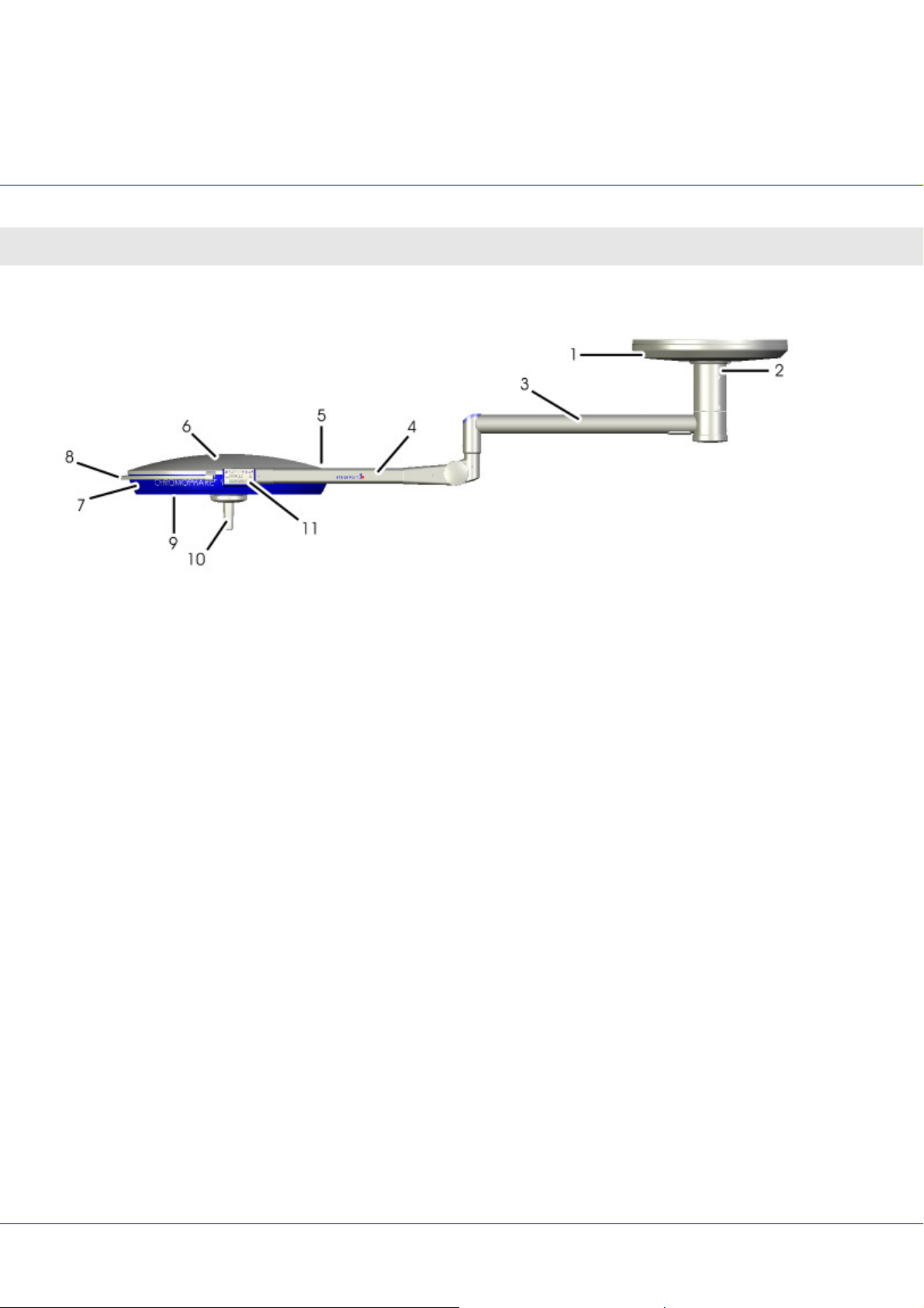
4.1.2
Single lights, flat cardanic (N.C.) ..................32
4.1.3
Light combination, classic cardanic (A.C.)
/ shortened classic cardanic (sA.C.) ............33
4.1.4
Light combination, flat cardanic (N.C.) .......34
4.1.5
Handle assembly..........................................34
5 Sub-assembly .................................................................... 36
5.1 Light head....................................................................36
3
Page 4

LED surgical lights, single and combination lights CHROMOPHARE® E 778, E 668, E 558
General
5.1.1
CHROMOPHARE® E 778................................ 36
5.1.2
CHROMOPHARE® E 668................................ 40
5.1.3
CHROMOPHARE® E 558................................ 44
5.2 Cardanics.................................................................... 48
5.2.1
Classic cardanic (AC, carcanic control) ..... 49
5.2.2
Classic cardanic (AC, wall control).............. 50
5.2.3
Flat cardanic (NC) ....................................... 51
6 Connectors.........................................................................52
6.1 Pin configuration.......................................................... 52
6.1.1
Sliding contacts............................................ 53
7 Spring arm..........................................................................54
7.1 Spring arm classic cardanic (AC)................................ 54
7.2 Spring arm flat cardanic (NC, cardanic control) ........ 56
7.3 Spring arm flat cardanic (NC, wall control)................. 57
8 Swivel arm ..........................................................................58
9 Keyboard............................................................................59
9.1 CHROMOPHARE® E 778, E 668, E 558 ......................... 59
10 Wallbox...............................................................................61
10.1 Flush mounted............................................................. 61
10.2 Surface mounted ........................................................ 61
10.3 Flush mounted in tableau ........................................... 62
11 Connecting the electricity .................................................63
11.1 Electrical connection on the ceiling tube................... 64
11.2 Electrical connections on the mounting plate ........... 67
11.2.1 Electrical connections for ChromoVision
camera system HD and 1 C........................ 69
11.2.2 Electrical connections for ChromoVision
ECO camera system ................................... 70
11.2.3 Electrical connections with wall control box 71
11.3 Connecting the camera distribution board................ 72
11.3.1 ChromoVision camera system HD and
1 C ............................................................... 72
11.3.2 ChromoVision ECO camera system .......... 73
12 Mechanical adjustments ...................................................74
4
Page 5

LED surgical lights, single and combination lights CHROMOPHARE® E 778, E 668, E 558
General
12.1 Diagrams .....................................................................74
12.2 Adjusting the brakes.....................................................75
12.3 Adjusting the height stop and counterweight .............78
13 Maintenance and inspection............................................ 81
13.1 Safety ......................................................................81
13.2 Cleaning, disinfection and sterilization ........................82
13.3 Maintenance schedule ...............................................88
13.4 Maintenance ...............................................................89
13.4.1 Function tests before each use....................89
13.4.2 LED modul replacement ..............................89
13.4.3 Replacing (on-site) fuses ..............................93
14 Service Menu ..................................................................... 94
15 Appendix ........................................................................... 96
15.1 Consumables ..............................................................96
15.2 Diagrams .....................................................................98
15.2.1 CHROMOPHARE E 778 ................................98
15.2.2 CHROMOPHARE E 778 with
ChromoVision HD and 1 C (NTSC) ............100
15.2.3 CHROMOPHARE E 778 with
ChromoVision HD and 1 C (PAL) ...............102
15.2.4 CHROMOPHARE E 668 ..............................104
15.2.5 CHROMOPHARE E 668 with
ChromoVision HD and 1 C (NTSC) ............105
15.2.6 CHROMOPHARE E 668 with
ChromoVision HD and 1 C (PAL) ...............106
15.2.7 CHROMOPHARE E 558 ..............................107
15.2.8 CHROMOPHARE E 558 with
ChromoVision HD and 1 C (NTSC) ............108
15.2.9 CHROMOPHARE E 558 with
ChromoVision HD and 1 C (PAL) ...............109
15.3 Fuses, terminal voltages ............................................110
15.3.1 Fuses...........................................................110
15.3.2 Terminal voltages .......................................110
15.4 Information on electromagnetic compatibility (EMC)111
15.4.1 Guidelines and manufacturer's
declaration – Electromagnetic emissions..111
5
Page 6

LED surgical lights, single and combination lights CHROMOPHARE® E 778, E 668, E 558
General
15.4.2 Guidelines and manufacturer's
declaration – Electromagnetic
interference immunity................................ 111
16 Index.................................................................................113
6
Page 7

LED surgical lights, single and combination lights CHROMOPHARE® E 778, E 668, E 558
1 General
1.1 About this operating manual
This operating manual provides important instructions on how to
handle the device. For safe operation, observe all safety and
operating instructions.
Local accident prevention and general safety regulations also
apply.
Read the operating manual thoroughly before beginning any
work. The manual is considered part of the product and must be
kept in the vicinity of the device at all times for reference by
personnel.
If the device is transferred, the operating manual must be
included.
General
The illustrations in this manual are intended to provide a better
understanding of the device; they are not necessarily drawn to
scale and may deviate slightly from the actual model.
7
Page 8
LED surgical lights, single and combination lights CHROMOPHARE® E 778, E 668, E 558
General
1.2 Definition of symbols used
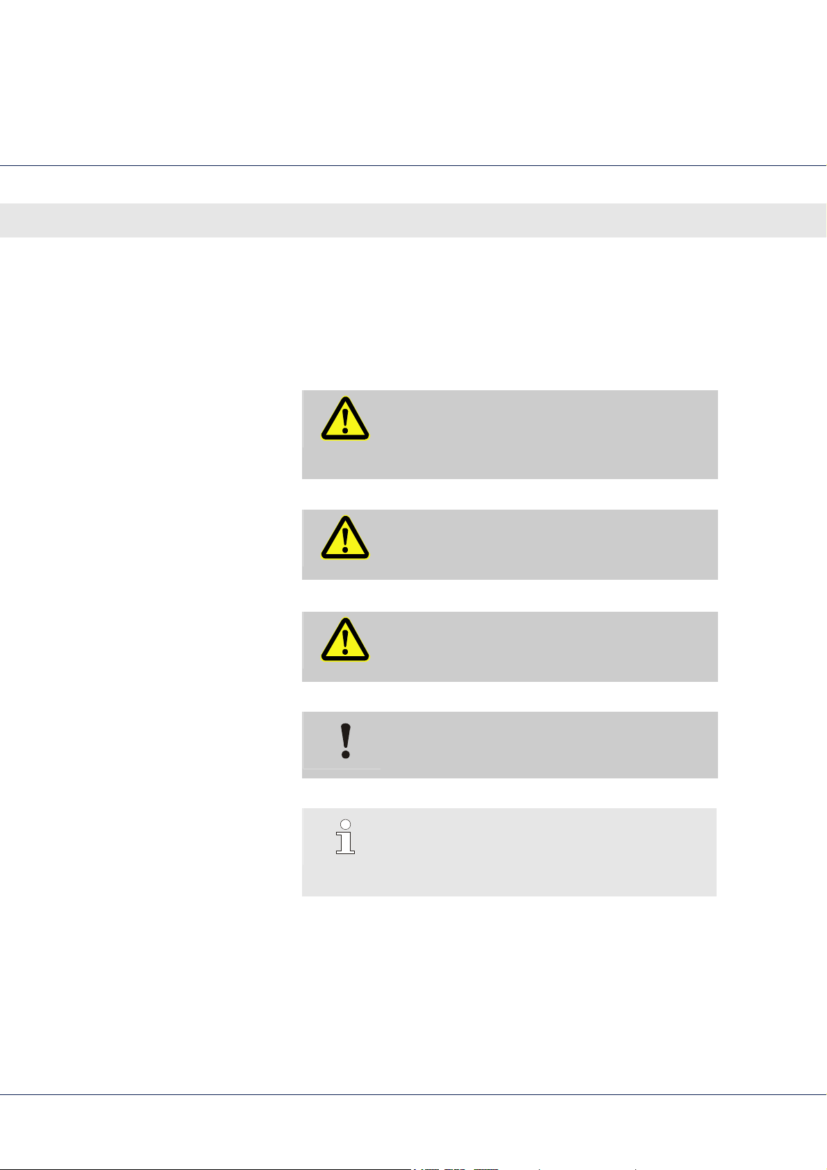
Warnings Symbols are used to indicate warnings in this manual. A signal
word that reflects the extent of the danger precedes each
warning.
Observe all warning notices and exercise extreme caution to
Tips and recommendations
prevent accidents, injuries and property damage.
DANGER!
Indicates an immediately dangerous situation that,
if not avoided, will result in death or serious bodily
injury.
WARNING!
Indicates a possibly dangerous situation that, if not
avoided, can result in death or serious bodily injury.
CAUTION!
Indicates a possibly dangerous situation that, if not
avoided, can result in moderate or minor injuries.
CAUTION!
Indicates a possibly dangerous situation that, if not
avoided, can result in damage to property.
NOTE!
Highlights useful tips, recommendations and
information for efficient and trouble-free
operation.
8
Page 9

LED surgical lights, single and combination lights CHROMOPHARE® E 778, E 668, E 558
General
Special safety notices To draw attention to particular dangers, the following symbol is
used in combination with safety notices:
DANGER!
Risk of death from electrical current!
Indicates life-threatening situations resulting from
electrical current. Disregarding the safety notice can
result in serious injury or death.
Work may be performed by electrical technicians
only.
9
Page 10

LED surgical lights, single and combination lights CHROMOPHARE® E 778, E 668, E 558
General
1.3 Limited liability
All specifications and notices in this manual were compiled using
applicable standards and regulations, the current state of
technology and our many years of experience and knowledge.
The manufacturer assumes no liability for damages resulting from
Non-compliance with the operating instructions.
Improper operation.
Work performed by untrained personnel.
Unauthorized modifications.
Technical changes.
Installation of non-approved spare parts.
Performance of unauthorized installation and maintenance
work.
Explanations and illustrations presented herein may deviate from
the actual product delivered in the case of special models,
additional options or the latest technical changes.
Furthermore, all obligations agreed to in the delivery contract, the
general terms and conditions, the manufacturer's delivery terms,
and any regulations legally valid at the time the contract is
concluded apply.
We reserve the right to make technical modifications to improve
and further develop the product.
10
Page 11

LED surgical lights, single and combination lights CHROMOPHARE® E 778, E 668, E 558
1.4 Copyright protection
1.5 Consumables
General
The operating manual should be treated as confidential. It is
exclusively for the use of persons handling the device. The
operating manual may not be transferred to third parties without
written approval from BERCHTOLD.
NOTE!
The specifications, text, drawings, pictures and
other illustrations contained herein are protected
by copyright and are subject to industrial property
rights. Improper application is punishable by law.
Making photocopies of any type or form, including excerpts
hereof, as well as using and/or sharing the content of this manual
requires written consent from BERCHTOLD. Violators will be liable for
damages. Further claims remain reserved.
WARNING!
Risk of injury if incorrect consumables used.
Incorrect or defective consumables can cause
damage, malfunction or complete failure of the
product and compromise safety.
Therefore:
– Use only original BERCHTOLD parts.
Purchase consumables from authorized dealers or directly from
BERCHTOLD (address back of manual).
11
Page 12

LED surgical lights, single and combination lights CHROMOPHARE® E 778, E 668, E 558
General
1.6 Warranty provisions
The warranty provisions and general terms and conditions can be
found on and downloaded from the Internet ( back of manual).
1.7 Customer service
For technical questions, contact the BERCHTOLD Technical
Customer Service.
To find out who your contact is, call, fax, e-mail or contact us via
the Website at any time ( back of manual).
1.8 CE mark
The device meets the requirements of the EU directive on medical
products 93/42/EWG.
You will find the CE mark on the model plate ( model plate).
12
Page 13

LED surgical lights, single and combination lights CHROMOPHARE® E 778, E 668, E 558
2 Safety
This section provides an overview of all important safety
information for optimal protection of personnel and safe and
trouble-free operation.
Non-compliance with the operating and safety instructions in this
2.1 Responsibility of the operator
manual can result in considerable danger.
The device is used in a commercial space. Therefore, the
operator of the device is subject to legal workplace safety
regulations.
In addition to the occupational safety warnings presented in this
manual, the operator must observe all the safety, accidentprevention and environmental protection regulations related to
the field of application. In particular, the following apply:
The operator must familiarize him- or herself with the valid
occupational safety regulations and identify by means of a risk
assessment any additional risks that result from the specific
working conditions where the device is used. Such risks must be
presented in the form of operating instructions.
Safety
For the entire duration of device use, the operator must verify
that the operating instructions created comply with current
regulations and modify them if necessary.
The operator must control and define clearly the responsibilities
for installing, operating, maintaining and cleaning the device.
The operator must ensure that all employees who handle the
device have read and understood the operating manual.
Furthermore, the operator must periodically train personnel and
review the dangers.
The operator must provide personnel with the required
protective equipment.
The operator is also responsible for keeping the device in proper
technical working order; the following apply:
The operator must adhere to the maintenance intervals
( Maintenance Schedule) specified in this manual.
The operator must have all safety facilities checked regularly
for proper function and completeness.
13
Page 14

LED surgical lights, single and combination lights CHROMOPHARE® E 778, E 668, E 558
Safety
2.2 Personnel requirements
WARNING!
Risk of injury if operated by insufficiently trained
personnel!
Incorrect handling can result in serious bodily injury
and property damage.
Therefore:
– All activities are to be carried out only by
qualified personnel.
– Consult the manufacturer if there is any doubt
concerning maintenance activities.
– Repairs should be performed only by the
manufacturer or authorized technical
personnel.
The following qualifications apply for these various ranges of tasks:
Medical specialists (surgeons, surgical personnel)
are able to safely perform the assigned tasks by virtue of their
medical education, knowledge and experience.
Medical specialists can independently detect, assess and
avoid possible hazards to themselves or the patients.
Medical specialists understand all valid regulations, guidelines
and standards required by law for safe use of the device and
are able to implement them accordingly.
Medical specialists have the required technical knowledge for
properly using the device in the area of application and
comply with all hygiene regulations for rooms used for medical
purposes and for the use of medical devices.
14
Page 15

LED surgical lights, single and combination lights CHROMOPHARE® E 778, E 668, E 558
Safety
Installation personnel
Only employees of BERCHTOLD or its authorized agents may
install and perform the initial start-up of the product.
Due to the heavy weight and high torque involved, only
appropriately trained and experienced technicians may install
surgical lighting.
A skilled electrician,
on the basis of his or her training, skills and experience and
well as knowledge of relevant standards and regulations is
able to work on electrical systems and can independently
detect and avoid possible dangers.
A skilled electrician is trained for the specific installation site and
knows the relevant standards and regulations.
15
Page 16

LED surgical lights, single and combination lights CHROMOPHARE® E 778, E 668, E 558
Safety
2.3 Intended use
The device is designed and constructed exclusively for the use as
described herein.
CHROMOPHARE® surgical lights are medical lights for use in
hospital treatment rooms. They provide localized lighting
focused on the patient's body for detecting and treating
disease, injury, and disability. Surgical lights may be used only in
rooms used for medical purposes and that have been
constructed in accordance with regulations VDE 0100-710 or
IEC 60364-7-10.
16
Page 17

LED surgical lights, single and combination lights CHROMOPHARE® E 778, E 668, E 558
Safety
WARNING!
Danger if not used as intended!
Dangerous situations can result any time the
device is used for purposes beyond or other than
those intended.
Therefore:
– Use the device only as intended.
– Strictly adhere to all specifications in this
operating manual.
– Only BERCHTOLD personnel or technicians
expressly authorized by BERCHTOLD may install,
modify or repair the devices.
The following uses are prohibited, in particular:
– Operation in areas where there is danger of
explosion. The surgical lights are a potential
source of ignition.
– Operation with a damaged underglass or filter
system.
– Placement of objects on the light head or
hanging objects from the swivel arms and light
head.
Claims of any kind due to damage resulting from improper use
are excluded.
The operator is solely responsible for damages resulting from
improper use.
17
Page 18

LED surgical lights, single and combination lights CHROMOPHARE® E 778, E 668, E 558
Safety
2.4 Reliability
As single lights, CHROMOPHARE® surgical lights provide a high
degree of reliability because the individual LED modules are
controlled separately from one another and the LED modules as
well as their emitters have a long service life. Additionally, the light
head is highly reliable because of the number of LEDs used.
If individual LEDs fail, the function of the light head is not
compromised. If individual LED modules fail, the intensity is
reduced.
Do not use single lights for operations during which a failure could
seriously endanger the patient.
Light combinations with two or even three light heads provide
greater security against light failure and provide better illumination
of the surgical field. They provide light from various angles and
maximum protection against failure through double and triple
redundancy. This is particularly true if they are connected to an
emergency power supply in addition to the mains supply. These
types of combination lights may be used in all medical disciplines
for lighting surgical areas.
18
Page 19

LED surgical lights, single and combination lights CHROMOPHARE® E 778, E 668, E 558
2.5 Personal protective equipment
To minimize health risks, personal protective equipment must be
worn while working.
Always wear the required protective equipment for the given
task.
Observe instructions posted in the work area regarding
Protective equipment for special
tasks
personal protective equipment.
Certain tasks require special protective equipment. These tasks
are discussed individually in the various sections of this manual.
The special protective equipment covered is:
Safety goggles
Protect the eyes from projectile objects and fluids.
Safety
2.6 Specific risks
The following section lists residual risks identified by a risk analysis.
Be sure to observe the safety instructions and warning notices
provided in the later sections of this manual to reduce health
risks and avoid dangerous situations.
19
Page 20

LED surgical lights, single and combination lights CHROMOPHARE® E 778, E 668, E 558
Safety
Electrical current
EMC risks (flat screens)
DANGER!
Risk of death from electrical current!
Touching live electrical components is life
threatening. Damage to insulation or individual
components can cause fatal injury.
Therefore:
– If insulation is damaged, immediately switch off
power supply and initiate repairs.
– Electrical work is to be performed by skilled
electricians only.
– To perform any electrical work, disconnect the
unit from the power supply and verify that it is
dead.
– Before performing any maintenance, cleaning
or repairs, switch off the power supply and
ensure it cannot be accidentally switched on.
– Do not bypass or deactivate fuses. Make sure
the amperage is correct when changing fuses.
– Keep conductive parts away from humidity. It
can cause a short circuit.
WARNING!
Use of non-EMC flat screens and switched-mode
power supplies is life threatening.
Radiation disturbances can skew measurement
results of medical devices (e.g., monitoring of vital
functions). This can result in life-threatening
situations.
Therefore:
– Use only UL- or IEC-rated (UL60601-1, IEC
60601-1) flat screens and switched-mode
power supplies.
20
Page 21

LED surgical lights, single and combination lights CHROMOPHARE® E 778, E 668, E 558
Safety
2.7 Environmental protection
CAUTION!
Environmental hazard from incorrect handling!
Incorrect handling of environmentally hazardous
substances, especially incorrect disposal, can
result in significant damage to the environment.
Therefore:
– Always observe the following instructions.
– Take appropriate measures immediately should
hazardous substances accidentally be
released into the environment. In case of
doubt, notify the responsible local authorities
The following environmentally hazardous substances are used:
regarding the damage.
Lubricants Lubricants such as grease and oil contain poisonous substances.
They should not be released into the environment. Disposal must
be handled by disposal specialists.
2.8 Labeling
Hot surface (on the lighting system)
Hot surfaces are not always obvious.
Allow to cool before handling.
Electrical current (on the soffit)
Only skilled electricians may work in these areas.
21
Page 22

LED surgical lights, single and combination lights CHROMOPHARE® E 778, E 668, E 558
Technical Data
3 Technical Data
3.1 General information
The cardanic suspension of CHROMOPHARE® surgical lights is
available on a number of models.
Classic cardanic (A.C.) for normal ceiling heights.
Shortened classic cardanic (sA.C.) for medium-high to low
ceiling heights.
Flat cardanic (N.C.) for low ceiling heights.
Features in the following tables are marked "A.C.," "sA.C." or "N.C.,"
as appropriate.
The weights and maximum torques are specific to single lights
(including transformer and anchor plate), each with a 180-mm
CHROMOPHARE® E 778
ceiling tube and a 900-mm cantilever (Ø 125 mm).
Specifications Value Unit
Weight incl. transformer 70 kg
Max. torque 531 Nm
Light head diameter 78 cm
Light emission surface area 3590 cm2
Max. swivel radius 235,5 cm
Lowest position of light head (N.C.) 128 cm
Highest position of light head (N.C.) 228 cm
Lowest position of light head (sA.C.) 117 cm
Highest position of light head (sA.C.) 220 cm
Lowest position of light head (A.C.) 113 cm
Highest position of light head (A.C.) 220 cm
Clearance, single light (N.C.)
(with a 245.5-cm ceiling height)
200 cm
22
Page 23

LED surgical lights, single and combination lights CHROMOPHARE® E 778, E 668, E 558
Technical Data
CHROMOPHARE® E 668
CHROMOPHARE® E 558
Specifications Value Unit
Weight incl. transformer 60 kg
Max. torque 495 Nm
Light head diameter 64 cm
Light emission surface area 2352 cm2
Max. swivel radius 233 cm
Lowest position of light head (N.C.) 128,5 cm
Highest position of light head (N.C.) 228 cm
Lowest position of light head (A.C.) 115 cm
Highest position of light head (A.C.) 220 cm
Clearance, single light (N.C.)
(with a 245.5-cm ceiling height)
200 cm
Specifications Value Unit
Weight incl. transformer 58 kg
Max. torque 445 Nm
Light head diameter 58 cm
Light emission surface area 1766 cm2
Max. swivel radius 229,5 cm
Lowest position of light head (N.C.) 128,5 cm
Highest position of light head (N.C.) 229 cm
Lowest position of light head (A.C.) 118 cm
Highest position of light head (A.C.) 223 cm
Clearance, single light (N.C.)
(with a 245.5-cm ceiling height)
200 cm
23
Page 24

LED surgical lights, single and combination lights CHROMOPHARE® E 778, E 668, E 558
Technical Data
3.2 Connection loads
CHROMOPHARE® E 778
Specifications Value Unit
100/120/127 V (AC) Transformer primary voltage
CHROMOPHARE® E 668
Power consumption at mains
220/230/240 V (AC)
300 VA (AC)
during mains operation
Power consumption at mains with
DC supply
200
VA (at
24-28 V DC)
AC frequency 50/60 Hz
Safety class 1
Specifications Value Unit
100/120/127 V (AC) Transformer primary voltage
Power consumption at mains
220/230/240 V (AC)
250 VA (AC)
during mains operation
Power consumption at mains with
DC supply
160
VA (at
24-28 V DC)
AC frequency 50/60 Hz
Safety class 1
24
Page 25

LED surgical lights, single and combination lights CHROMOPHARE® E 778, E 668, E 558
Technical Data
CHROMOPHARE® E 558
LED emitters for CHROMOPHARE®
E 778, E 668 and E 558
Specifications Value Unit
100/120/127 V (AC) Transformer primary voltage
Power consumption at mains
220/230/240 V (AC)
220 VA (AC)
during mains operation
Power consumption at mains with
DC supply
140
VA (at
24-28 V DC)
AC frequency 50/60 Hz
Safety class 1
The CHROMOPHARE® E 778, E 668 and E 558 surgical light is
equipped with an innovative light source, the LED ("light-emitting
diode").
In contrast to traditional halogen or high-intensity discharge lamps,
LEDs are characterized by a very long service life.
As a rule, traditional bulbs must be replaced after 1,000 to 5,000
hours of operation, while LEDs have a longer service life of at least
25,000 hours of operation.
The CHROMOPHARE® E 778 consists of a total of 14 LED modules
respectively 168 LEDs. The modules vary in size and shape as
follows:
10 hexagonal modules
4 semi-circular modules
The CHROMOPHARE® E 668 consists of a total of 8 hexagonal
LED modules, respectively 96 LEDs.
The CHROMOPHARE® E 558 consists of a total of 6 hexagonal
LED modules, respectively 72 LEDs.
The modules as such consist of 12 warm- and cool-white LEDs.
Additionally, all the modules are controlled individually (CAN
interface) for simplified service.
25
Page 26

LED surgical lights, single and combination lights CHROMOPHARE® E 778, E 668, E 558
Technical Data
3.3 Operating conditions
All models
Specifications Value Unit
Ambient temperature 10…40 °C
Relative humidity,
30…75 %
non-condensing
Barometric pressure 700…1060 hPa
3.4 Performance
The technical lighting data provided in the following tables has a
tolerance of ± 10%.
26
Page 27

LED surgical lights, single and combination lights CHROMOPHARE® E 778, E 668, E 558
Technical Data
CHROMOPHARE® E 778
Specifications Value Unit
Color temperature levels
(only with Color Select option)
Standard color temperature level
3600
4000
4500
5000
4500
K
K
K
K
K
(without Color Select option)
Intensity Ec at 1 m 160
Electronic brightness control
80–160 klx
Total radiant power
600
klx
W/m2
at max. intensity
Total radiant power/intensity 3,7
mW/
(m2 lx)
Color rendering index Ra 95
Circadian effect coefficient acv 0,72
Light field diameter 15-29
cm
d10 Light field,
∅ at 10 % of max. intensity
d50 Light field,
∅ at 50 % of max. intensity
Residual brightness when obstructed by one
mask, with reference to Ec
Residual brightness when obstructed by two
masks, with reference to Ec
Residual brightness in standardized tube, in
reference to Ec
Residual brightness in standard tube with
one shader, in relation to Ec
Residual brightness in standard tube with
two shaders, in relation to Ec
Depth of illumination L1 + L2 75
15
9,6
73 %
52 %
91 %
66 %
47 %
cm
cm
cm
27
Page 28

LED surgical lights, single and combination lights CHROMOPHARE® E 778, E 668, E 558
Technical Data
CHROMOPHARE® E 668
Specifications Value Unit
Color temperature levels
(only with Color Select option)
Standard color temperature level
3600
4000
4500
5000
4500
K
K
K
K
K
(without Color Select option)
Intensity Ec at 1 m
160
klx
Electronic brightness control 80–160 klx
Total radiant power
600
W/m2
at max. intensity
Total radiant power/intensity
3,7
mW/
(m2 lx)
Color rendering index Ra 95
Circadian effect coefficient acv 0,72
Light field diameter 15-29 cm
d10 Light field,
15 cm
∅ at 10 % of max. intensity
d50 Light field,
9,6
cm
∅ at 50 % of max. intensity
Residual brightness when obstructed by one
70
%
mask, with reference to Ec
Residual brightness when obstructed by two
50
%
masks, with reference to Ec
Residual brightness in standardized tube, in
100
%
reference to Ec
Residual brightness in standard tube with
70
%
one shader, in relation to Ec
Residual brightness in standard tube with
50
%
two shaders, in relation to Ec
Depth of illumination L1 + L2
28
80
cm
Page 29

LED surgical lights, single and combination lights CHROMOPHARE® E 778, E 668, E 558
Technical Data
CHROMOPHARE® E 558
Specifications Value Unit
Color temperature levels
(only with Color Select option)
Standard color temperature level
3600
4000
4500
5000
K
K
K
K
4500 K
(without Color Select option)
Intensity Ec at 1 m 120 klx
Electronic brightness control 60–120 klx
Total radiant power
440 W/m2
at max. intensity
Total radiant power/intensity 3,7 mW/
(m2 lx)
Color rendering index Ra 95
Circadian effect coefficient acv 0,72
Light field diameter 15-29 cm
d10 Light field,
15 cm
∅ at 10 % of max. intensity
d50 Light field,
9,6 cm
∅ at 50 % of max. intensity
Residual brightness when obstructed by one
56 %
mask, with reference to Ec
Residual brightness when obstructed by two
46 %
masks, with reference to Ec
Residual brightness in standardized tube, in
100 %
reference to Ec
Residual brightness in standard tube with
56 %
one shader, in relation to Ec
Residual brightness in standard tube with
46 %
two shaders, in relation to Ec
Depth of illumination L1 + L2 85 cm
29
Page 30
LED surgical lights, single and combination lights CHROMOPHARE® E 778, E 668, E 558
Technical Data
3.5 Emissions
A full explanation on compliance with EMC guidelines can be
found in the appendix.
3.6 Model plate
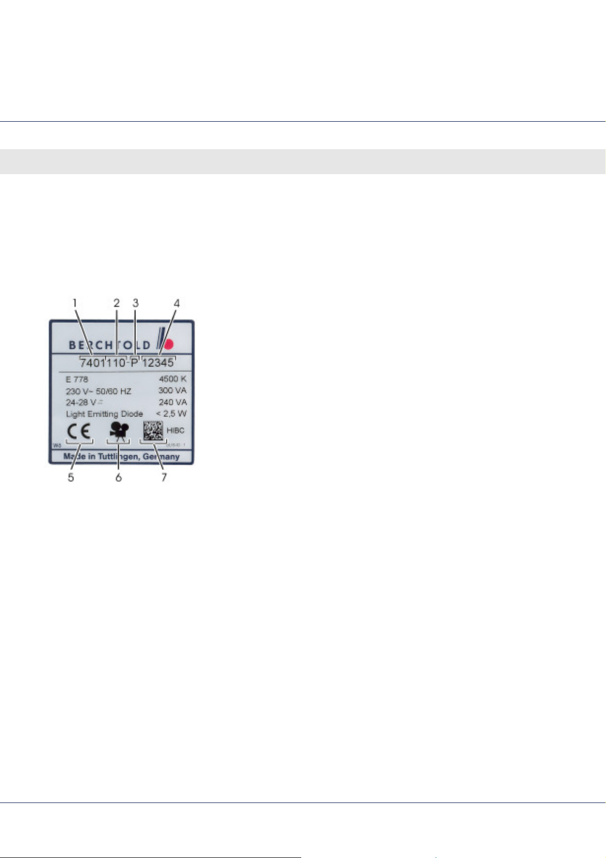
The model plate is located next to the suspension installation point
on the housing of the light head.
It contains the following information:
1 Version number
2 Model number
3 Year of manufacture (A = 1993, B = 1994, …)
4 Sequential numbering
Fig. 1 Model plate
5 CE mark
6 Symbol for camera preparation (optional)
7 Health Industry Bar Code
30
Page 31
LED surgical lights, single and combination lights CHROMOPHARE® E 778, E 668, E 558
Design and function
4 Design and function
4.1 Overview
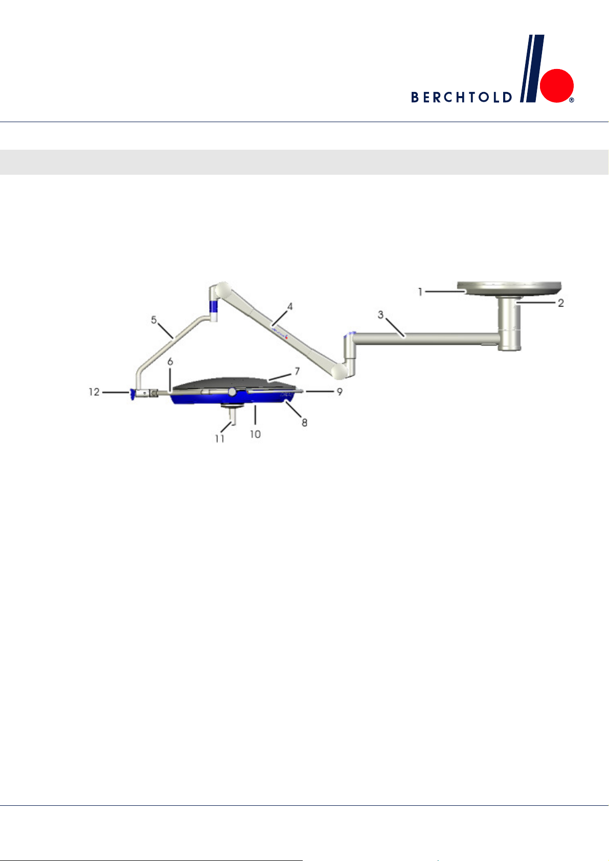
4.1.1 Single lights, classic cardanic (A.C.) / shortened classic cardanic (sA.C.)
Fig. 2 CHROMOPHARE E 778. E 668 and E 558 single light components, classic cardanic / shortened classic cardanic
(without height adjustment tube)
1 Soffit
2 Ceiling tube ∅ 125 mm
3 Swivel arm
4 Spring arm
5 Vertical gimbal joint
6 Horizontal gimbal joint
7 Lamp housing hood
8 Light frame
9 Rail
10 Light emission lens (facing)
11 Handle assembly
12 Control panel
31
Page 32
LED surgical lights, single and combination lights CHROMOPHARE® E 778, E 668, E 558
Design and function
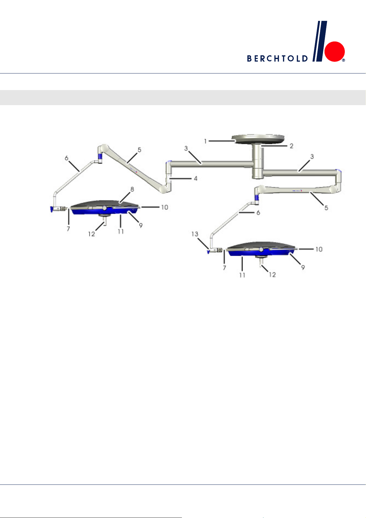
4.1.2 Single lights, flat cardanic (N.C.)
Fig. 3 CHROMOPHARE E 778, E 668 and E 558 single light components, flat cardanic (without height adjustment tube)
1 Soffit
2 Ceiling tube ∅ 125 mm
3 Swivel arm
4 Spring arm
5 Horizontal gimbal joint
6 Lamp housing hood
7 Light frame
8 Rail
9 Light emission lens (facing)
10 Handle assembly
11 Control panel
32
Page 33
LED surgical lights, single and combination lights CHROMOPHARE® E 778, E 668, E 558
Design and function
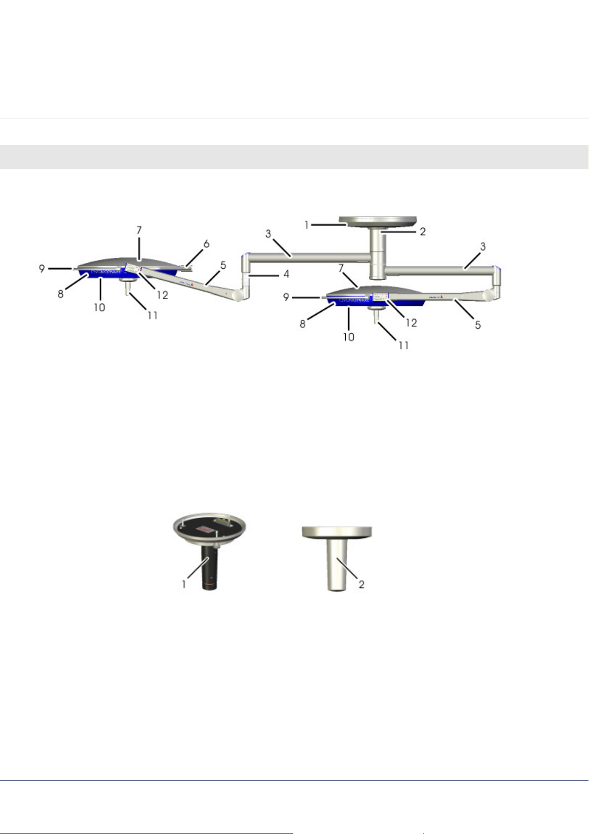
4.1.3 Light combination, classic cardanic (A.C.) / shortened classic cardanic (sA.C.)
Fig. 4 CHROMOPHARE E 778 with E 778 light combination components, classic cardanic / shortened classic cardanic
1 Soffit
2 Ceiling tube ∅ 125 mm
3 Swivel arm
4 Height adjustment tube
5 Spring arm
6 Vertical gimbal joint
7 Horizontal gimbal joint
8 Control panel
9 Light frame
10 Rail
11 Light emission lens (facing)
12 Handle assembly
13 Lamp housing hood
33
Page 34
LED surgical lights, single and combination lights CHROMOPHARE® E 778, E 668, E 558
Design and function
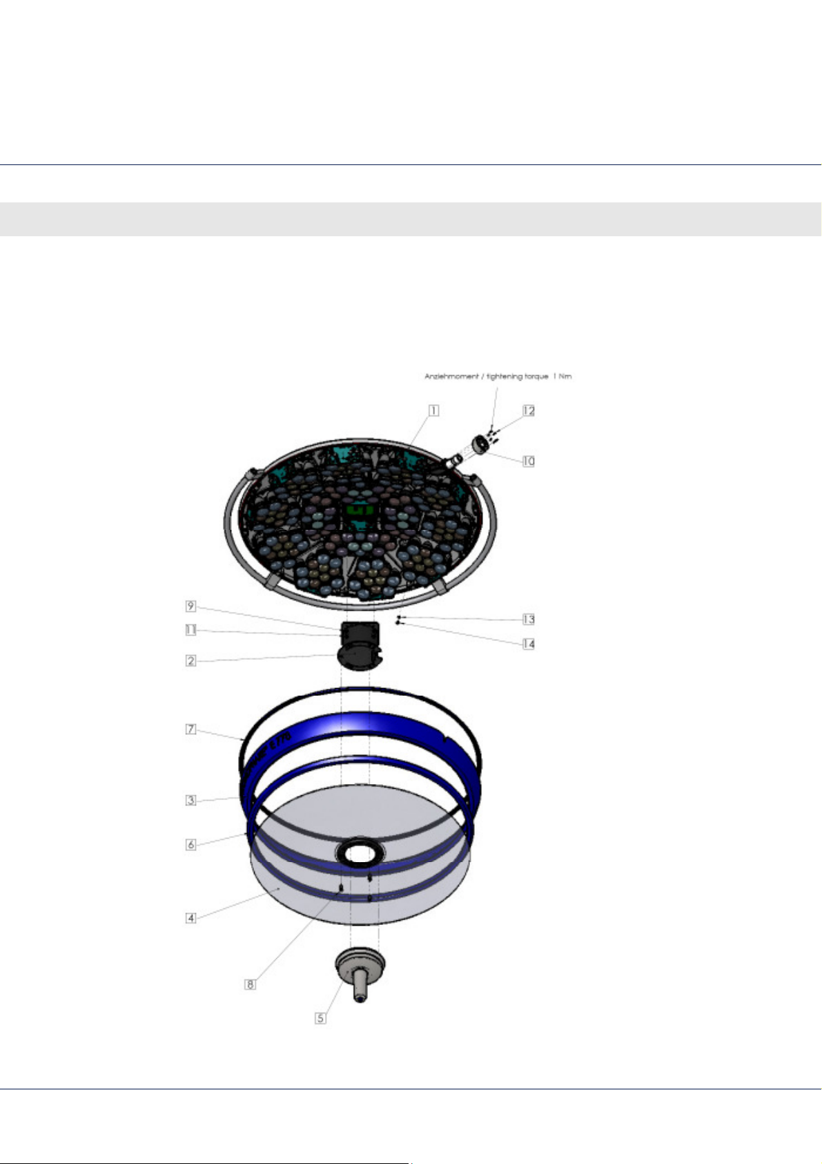
4.1.4 Light combination, flat cardanic (N.C.)
Fig. 5 CHROMOPHARE E 778 with E 778 light combination components, flat cardanic
1 Soffit
2 Ceiling tube ∅ 125 mm
3 Swivel arm
4 Height adjustment tube
5 Spring arm
6 Horizontal gimbal joint
7 Lamp housing hood
8 Light frame
9 Rail
10 Light emission lens (facing)
11 Handle assembly
12 Control panel
4.1.5 Handle assembly
Fig. 6 Overview of handle assembly
1 Focus
2 Handle sleeve
34
Page 35

LED surgical lights, single and combination lights CHROMOPHARE® E 778, E 668, E 558
Design and function
- NOTES -
35
Page 36
LED surgical lights, single and combination lights CHROMOPHARE® E 778, E 668, E 558
Sub-assembly
5 Sub-assembly
5.1 Light head
5.1.1 CHROMOPHARE® E 778
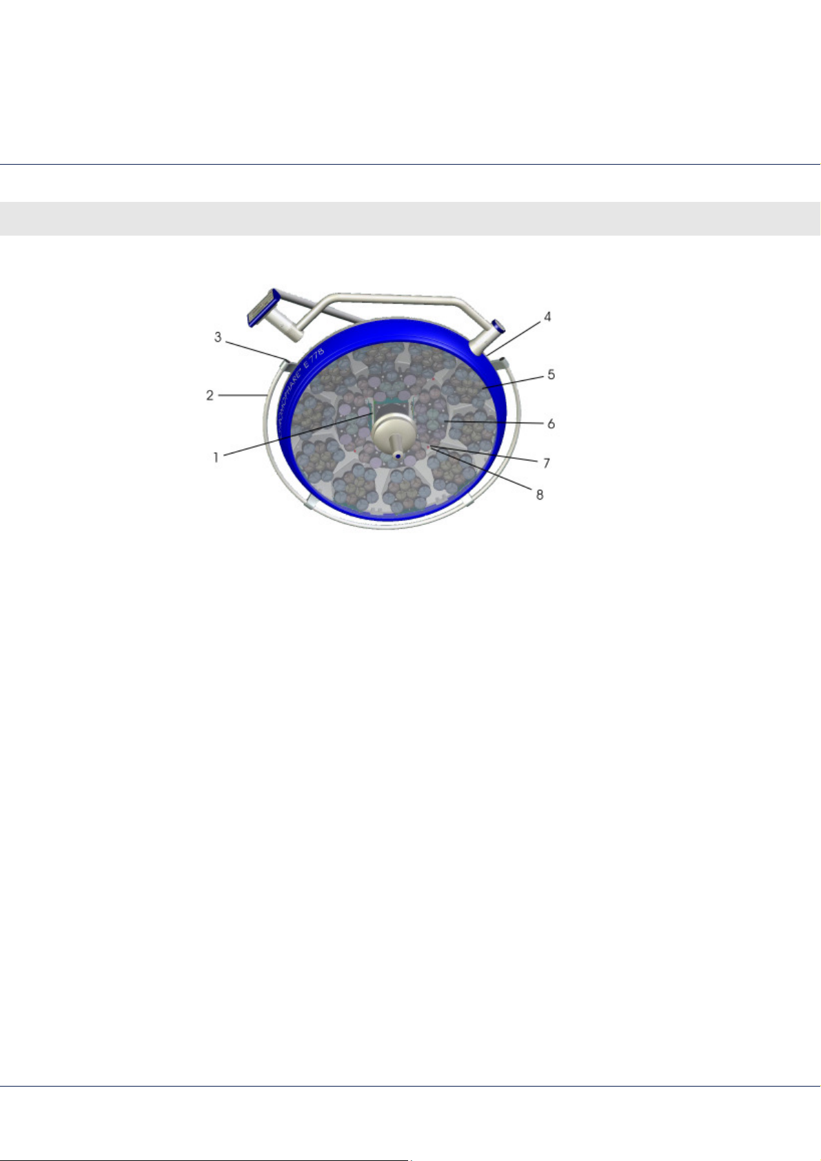
Fig. 7 Light head CHROMOPHARE® E 778
36
Page 37

LED surgical lights, single and combination lights CHROMOPHARE® E 778, E 668, E 558
Position Quantity Part No. Description
2 1 pcs 80036 Lower glass holder
3 1 pcs 80444 Frame
4 1 pcs 80037 Lower glass
5 1 pcs 80020 Focus mechanism
6 1 pcs 80413 Lower glass seal
7 1 pcs 80415 Frame seal
8 3 pcs 73714 Screw
9 4 pcs 357 Spring washer
Sub-assembly
10 1 pcs 80071 Side shaft cover
11 4 pcs 152 Screw M5X10 DIN 912-8,8
12 6 pcs 77035 Screw, DIN 965 - M 2.5 X 8 -A2
13 1 pcs 379 Washer A 4,3 DIN 6798 - A2
14 1 pcs 274 Screw M4X6 DIN 7985-A2
37
Page 38
LED surgical lights, single and combination lights CHROMOPHARE® E 778, E 668, E 558
Sub-assembly
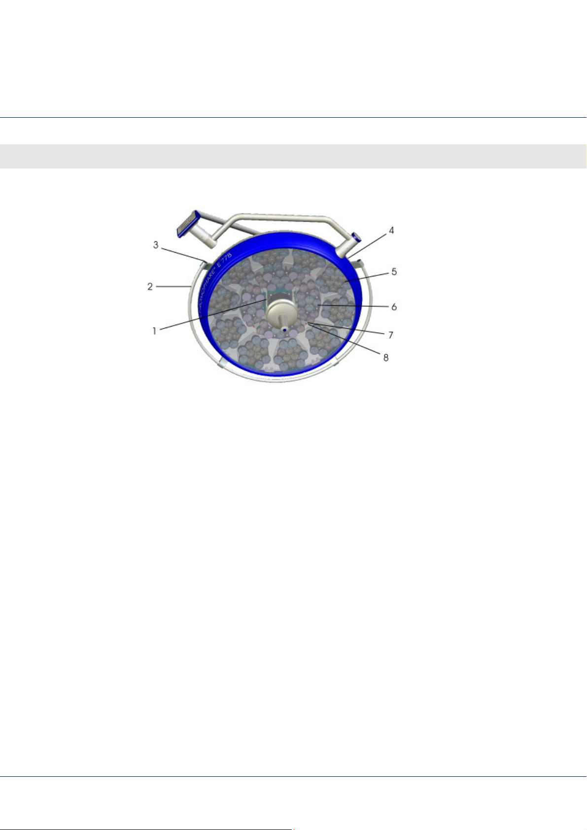
Fig. 8 Light head CHROMOPHARE® E 778
38
Page 39

LED surgical lights, single and combination lights CHROMOPHARE® E 778, E 668, E 558
Position Quantity Part No. Description
1 1 pcs 80046 Distribution board
2 1 pcs 80419 Rail
3 2 pcs 79203 Plastic plug
4 1 pcs 80017 Lamp housing hood
5 10 pcs 80322 LED module, hexagon
6 4 pcs 80324 LED module, semi-circular
7 46 pcs 81019 Spring washer DIN 137-A 4-zinc coated
Sub-assembly
8 46 pcs 80181 Screw
39
Page 40
LED surgical lights, single and combination lights CHROMOPHARE® E 778, E 668, E 558
Sub-assembly
5.1.2 CHROMOPHARE® E 668
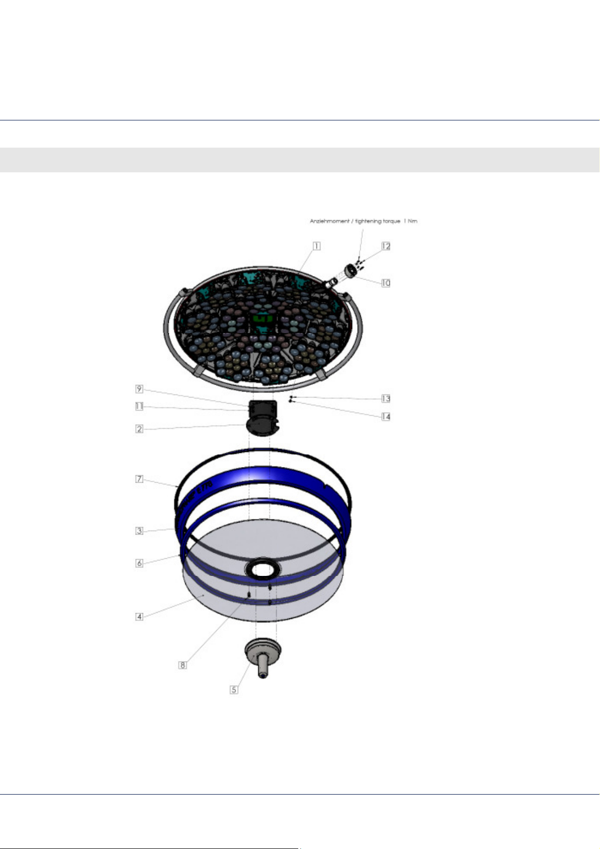
Fig. 9 Light head CHROMOPHARE® E 668
40
Page 41

LED surgical lights, single and combination lights CHROMOPHARE® E 778, E 668, E 558
Position Quantity Part No. Description
2 1 pcs 80036 Lower glass holder
3 1 pcs 80444 Frame
4 1 pcs 80037 Lower glass
5 1 pcs 80020 Focus mechanism
6 1 pcs 80413 Lower glass seal
7 1 pcs 80415 Frame seal
8 3 pcs 73714 Screw
Sub-assembly
9 4 pcs 357 Spring washer
10 1 pcs 80071 Side shaft cover
11 4 pcs 152 Screw M5X10 DIN 912-8,8
12 6 pcs 77035 Screw, DIN 965 - M 2.5 X 8 -A2
13 1 pcs 379 Washer A 4,3 DIN 6798 - A2
14 1 pcs 274 Screw M4X6 DIN 7985-A2
41
Page 42
LED surgical lights, single and combination lights CHROMOPHARE® E 778, E 668, E 558
Sub-assembly
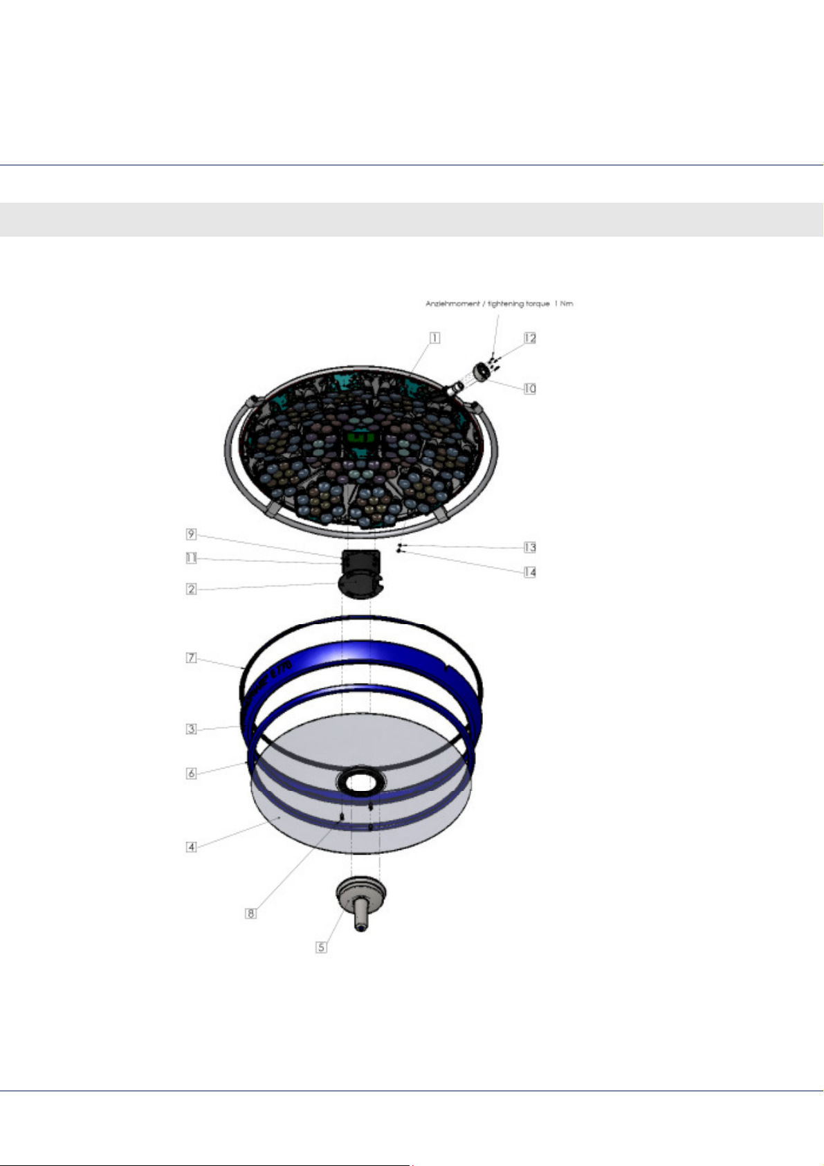
Fig. 10 Light head CHROMOPHARE® E 668
42
Page 43

LED surgical lights, single and combination lights CHROMOPHARE® E 778, E 668, E 558
Position Quantity Part No. Description
1 1 pcs 80046 Distribution board
2 1 pcs 80489 Rail
3 2 pcs 79203 Plastic plug
4 1 pcs 80485 Lamp housing hood
5 8 pcs 81087 LED module, hexagon
6 24 pcs 81019 Spring washer DIN 137-A 4-zinc coated
7 24 pcs 80181 Screw
Sub-assembly
43
Page 44
LED surgical lights, single and combination lights CHROMOPHARE® E 778, E 668, E 558
Sub-assembly
5.1.3 CHROMOPHARE® E 558
Fig. 11 Light head CHROMOPHARE® E 558
44
Page 45

LED surgical lights, single and combination lights CHROMOPHARE® E 778, E 668, E 558
Position Quantity Part No. Description
2 1 pcs 80468 Lower glass holder
3 1 pcs 80447 Frame
4 1 pcs 80455 Lower glass
5 1 pcs 80020 Focus mechanism
6 1 pcs 80453 Lower glass seal
7 1 pcs 80451 Frame seal
8 3 pcs 73714 Screw
Sub-assembly
9 4 pcs 257 Pan head tapping screw
10 1 pcs 80071 Side shaft cover
11 4 pcs 152 Screw M5X10 DIN 912-8,8
12 6 pcs 77035 Screw, DIN 965 - M 2.5 X 8 -A2
13 1 pcs 379 Washer A 4,3 DIN 6798 - A2
14 1 pcs 274 Screw M4X6 DIN 7985-A2
45
Page 46
LED surgical lights, single and combination lights CHROMOPHARE® E 778, E 668, E 558
Sub-assembly
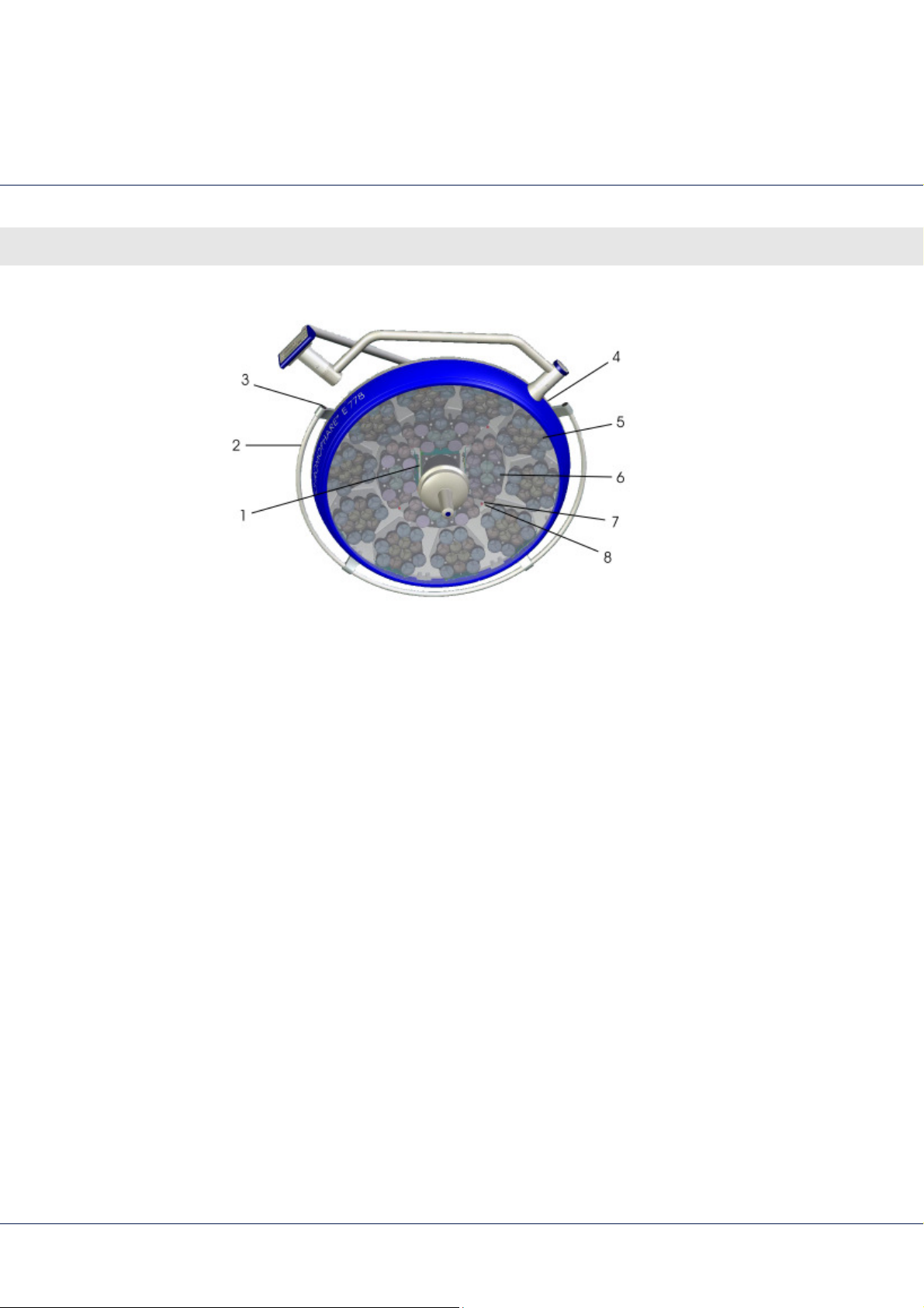
Fig. 12 Light head CHROMOPHARE® E 558
46
Page 47

LED surgical lights, single and combination lights CHROMOPHARE® E 778, E 668, E 558
Position Quantity Part No. Description
1 1 pcs 80046 Distribution board
2 1 pcs 80449 Rail
3 2 pcs 79203 Plastic plug
4 1 pcs 80445 Lamp housing hood
5 6 pcs 81087 LED module, hexagon
6 18 pcs 81019 Spring washer DIN 137-A 4-zinc coated
7 18 pcs 80181 Screw
Sub-assembly
47
Page 48

LED surgical lights, single and combination lights CHROMOPHARE® E 778, E 668, E 558
Sub-assembly
5.2 Cardanics
The cardanic suspension of CHROMOPHARE® surgical lights is
available on a number of models.
Classic cardanic (A.C.) for normal ceiling heights.
Shortened classic cardanic (sA.C.) for medium-high to low
ceiling heights.
Flat cardanic (N.C.) for low ceiling heights.
48
Page 49
LED surgical lights, single and combination lights CHROMOPHARE® E 778, E 668, E 558
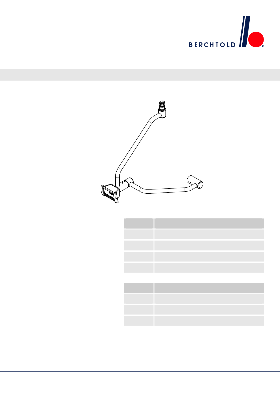
5.2.1 Classic cardanic (AC, carcanic control)
Sub-assembly
Fig. 13 AC cardanic with cardanic control
Part No. Description
80051 Cardanic E 778 AC (incl. harness)
80462 Cardanic E 778 sAC (incl. harness)
83050 Cardanic E 668 AC (incl. harness)
80470 Cardanic E 558 AC (incl. harness)
Part No. Description
500550 Harness cardanic E 778 AC 7-pole
500550 Harness cardanic E 778 sAC 7-pole
500550 Harness cardanic E 668 / E 558 AC 7-pole
49
Page 50
LED surgical lights, single and combination lights CHROMOPHARE® E 778, E 668, E 558
Sub-assembly
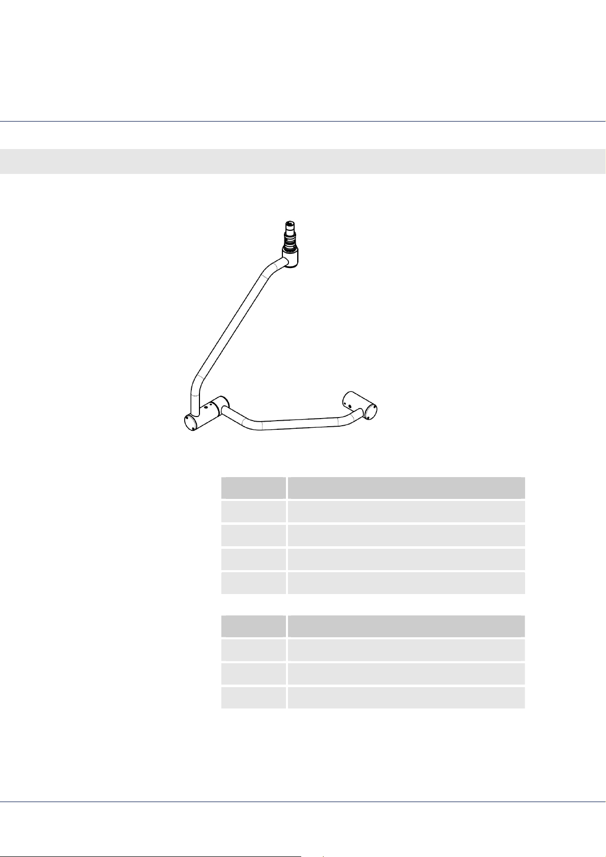
5.2.2 Classic cardanic (AC, wall control)
Fig. 14 AC cardanic with wall control
Part No. Description
80463 Cardanic E 778 AC (incl. harness)
80464 Cardanic E 778 sAC (incl. harness)
83051 Cardanic E 668 AC (incl. harness)
80471 Cardanic E 558 AC (incl. harness)
Part No. Description
500550 Harness cardanic E 778 AC 7-pole
500550 Harness cardanic E 778 sAC 7-pole
500550 Harness cardanic E 668 / E 558 AC 7-pole
50
Page 51
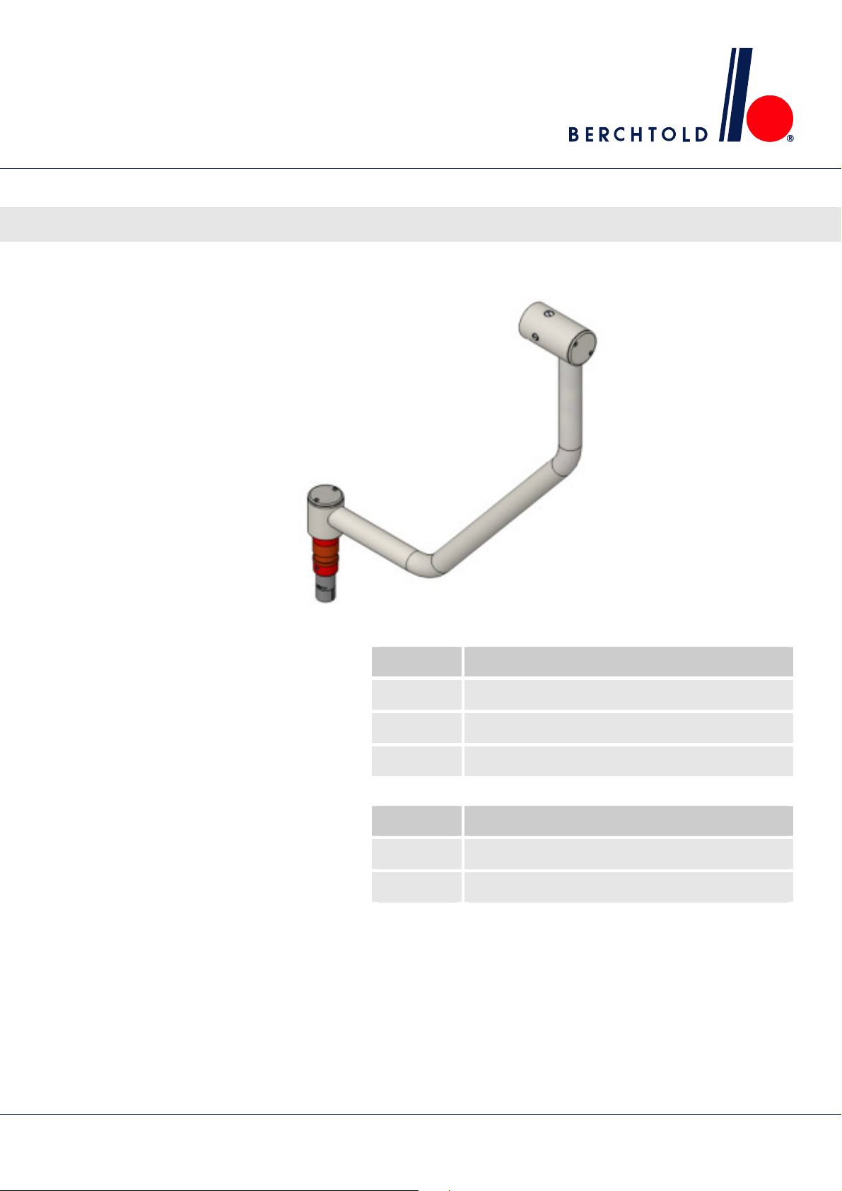
5.2.3 Flat cardanic (NC)
LED surgical lights, single and combination lights CHROMOPHARE® E 778, E 668, E 558
Sub-assembly
Fig. 15 NC cardanic
Part No. Description
80460 Cardanic E 778 NC (incl. harness)
83056 Cardanic E 668 NC (incl. harness)
80477 Cardanic E 558 NC (incl. harness)
Part No. Description
500551 Harness cardanic E 778 NC 7-pole
500568 Harness cardanic E 668 / E 558 NC 7-pole
51
Page 52
LED surgical lights, single and combination lights CHROMOPHARE® E 778, E 668, E 558
Connectors
6 Connectors
6.1 Pin configuration
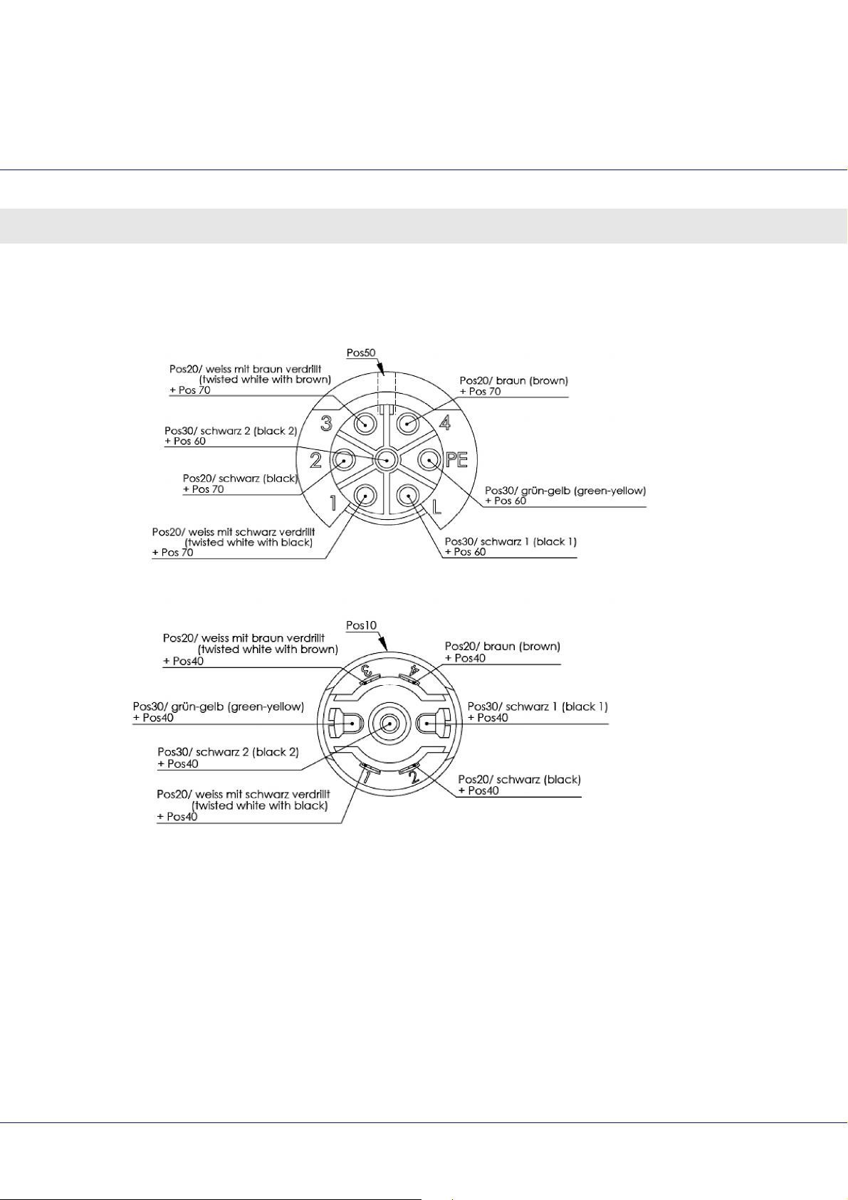
Fig. 16 Pin configuration overview
52
Page 53
6.1.1 Sliding contacts
LED surgical lights, single and combination lights CHROMOPHARE® E 778, E 668, E 558
Connectors
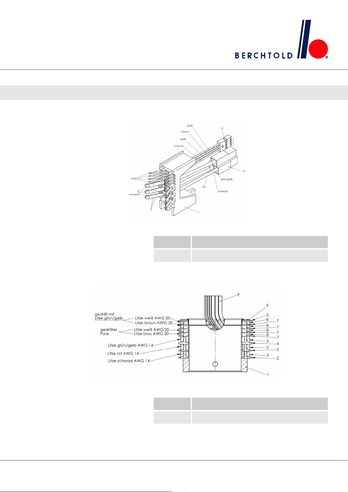
Fig. 17 Contact block
Fig. 18 Sliding ring
Part No. Description
78851 Contact block
Part No. Description
78849 Sliding ring
53
Page 54
LED surgical lights, single and combination lights CHROMOPHARE® E 778, E 668, E 558
Spring arm
7 Spring arm
7.1 Spring arm classic cardanic (AC)
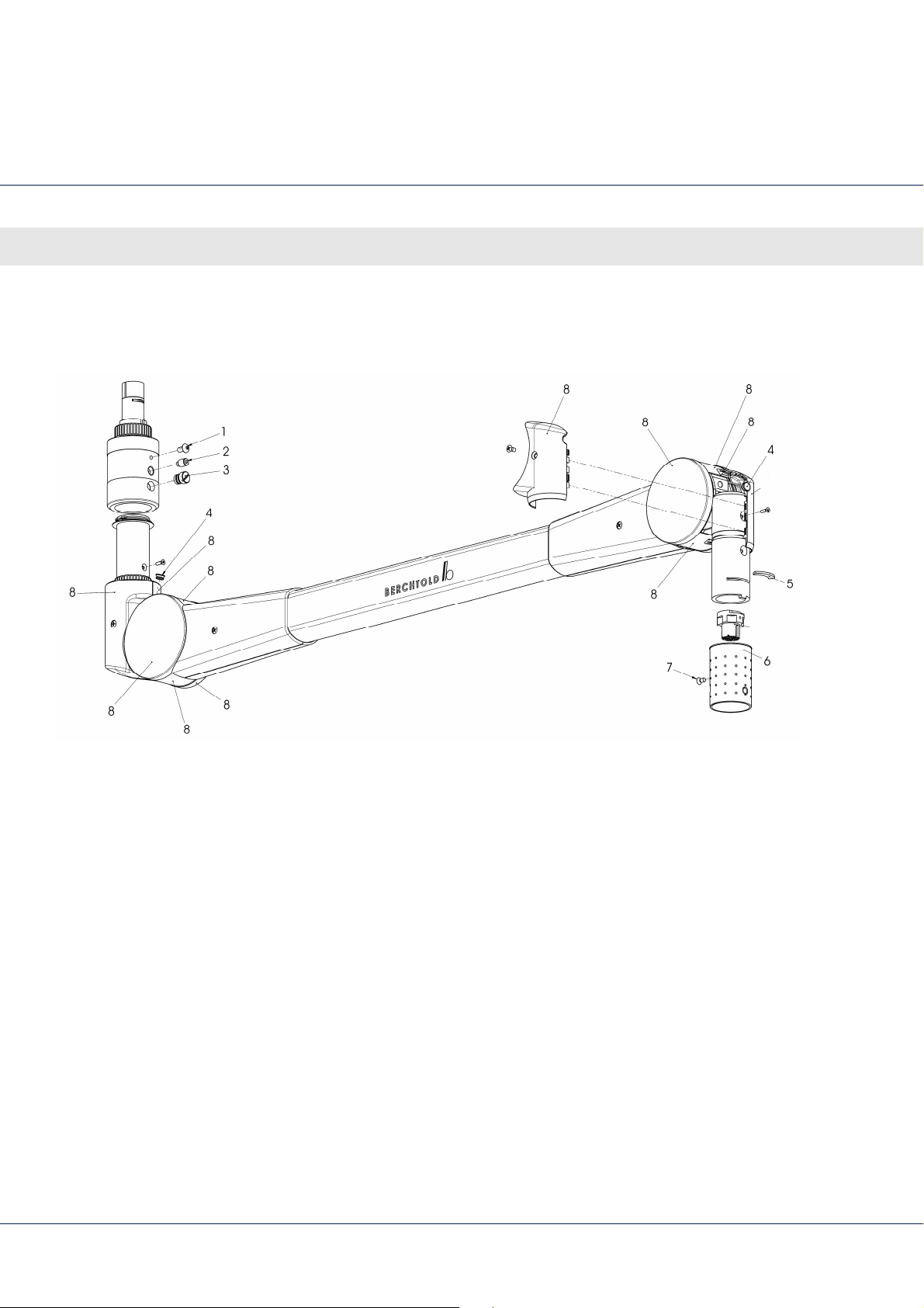
Fig. 19 Spring arm classic cardanic
54
Page 55

LED surgical lights, single and combination lights CHROMOPHARE® E 778, E 668, E 558
Position Quantity Part No. Description
1 45398 Head screw
2 64126 Pivot screw
3 84010 Brake screw
4 76026 Plug (included in part no. 80672)
5 76001 Safety segment
6 74191 Safety shaft (included in part no. 80672)
7 226 Screw for cover
Spring arm
8 80672 Spring arm cover set AC
Part No. Description
78905 Spring arm AC E 778
80554 Spring arm AC E 668 / E 558
55
Page 56
LED surgical lights, single and combination lights CHROMOPHARE® E 778, E 668, E 558
Spring arm
7.2 Spring arm flat cardanic (NC, cardanic control)
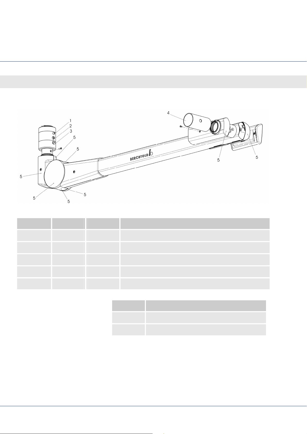
Fig. 20 Spring arm flat cardanic with cardanic control
Position Quantity Part No. Description
1 78979 counter sunk head screw
2 64126 Pivot screw
3 84010 Brake screw
4 74191 Safety shaft
5 80670 Spring arm cover set NC
Part No. Description
78906 Spring arm NC E 778
79760 Spring arm NC E 668 / E 558
56
Page 57
LED surgical lights, single and combination lights CHROMOPHARE® E 778, E 668, E 558
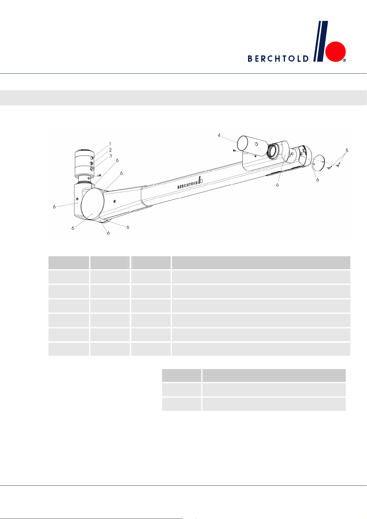
7.3 Spring arm flat cardanic (NC, wall control)
Spring arm
Fig. 21 Spring arm flat cardanic with wall control
Position Quantity Part No. Description
1 78979 counter sunk head screw
2 64126 Pivot screw
3 84010 Brake screw
4 74191 Safety shaft
5 226 Screw for cover
6 80670 Spring arm cover set NC
Part No. Description
78907 Spring arm NC E 778
79761 Spring arm NC E 668 / E 558
57
Page 58
LED surgical lights, single and combination lights CHROMOPHARE® E 778, E 668, E 558
Swivel arm
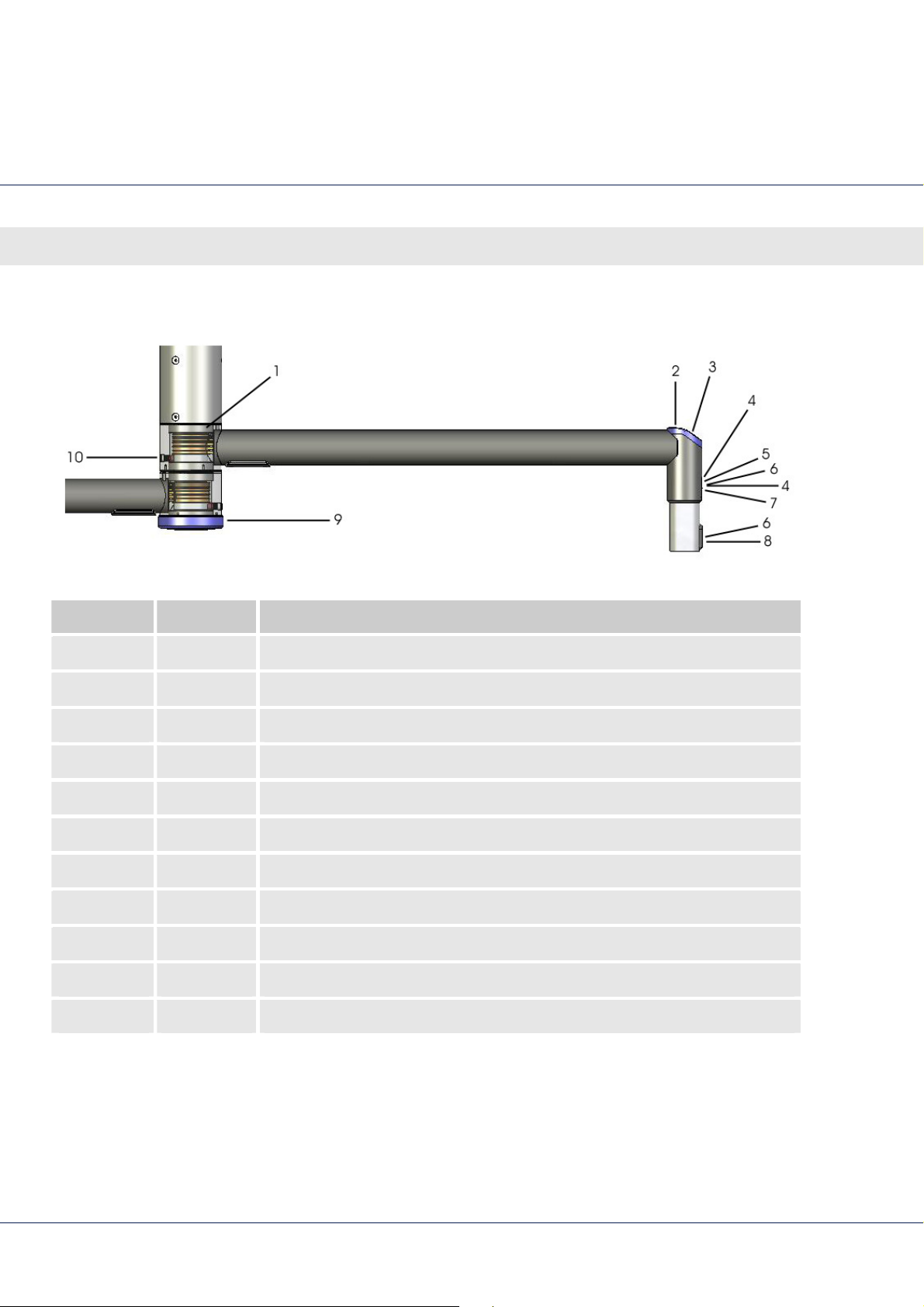
8 Swivel arm
Position Part No. Description
1 79695 Central column for single lights
79696 Central column for double lights
2 231 Screw DIN 966 - M 3 X 16-A2
3 78862 Cover blue Ø 70 mm
4 78979 Counter sunk head screw
5 78864 Cover for suspension
6 228 Screw, M3 x 0.5x10
7 78959 Bush
8 75187 Cover
9 78870 Jar cover
10 78867 Brake screw
58
Page 59
LED surgical lights, single and combination lights CHROMOPHARE® E 778, E 668, E 558
9 Keyboard
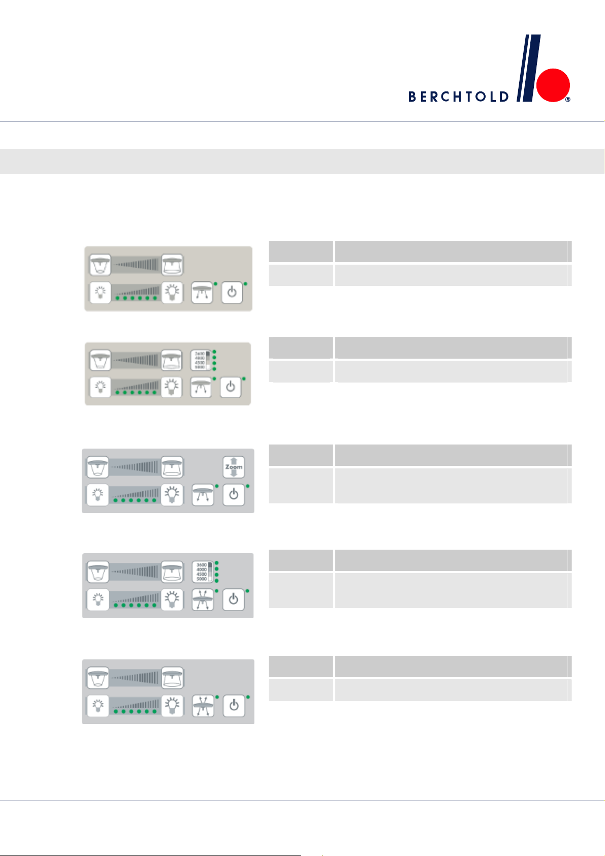
9.1 CHROMOPHARE® E 778, E 668, E 558
Part No. Description
79668 Key board foil with GuideLiteTM
Fig. 22: Keyboard with GuideLiteTM
Fig. 23: Keyboard with GuideLiteTM and
Color Select
Part No. Description
79667 Key board foil with GuideLiteTM and Color Select
Keyboard
Fig. 24: Keyboard with GuieLite
ChromoVision® ECO
Fig. 25: Keyboard with GuideLite
EndoLite® and Color Select
Fig. 26: Keyboard with GuideLite
EndoLite®
TM
and
TM
,
TM
and
Part No. Description
81182 Key board foil with GuieLite
ChromoVision® ECO
Part No. Description
81183 Key board foil with GuideLite
Color Select
Part No. Description
81184 Key board foil with GuideLite
TM
and
TM
, EndoLite® and
TM
and EndoLite®
59
Page 60
LED surgical lights, single and combination lights CHROMOPHARE® E 778, E 668, E 558
Keyboard
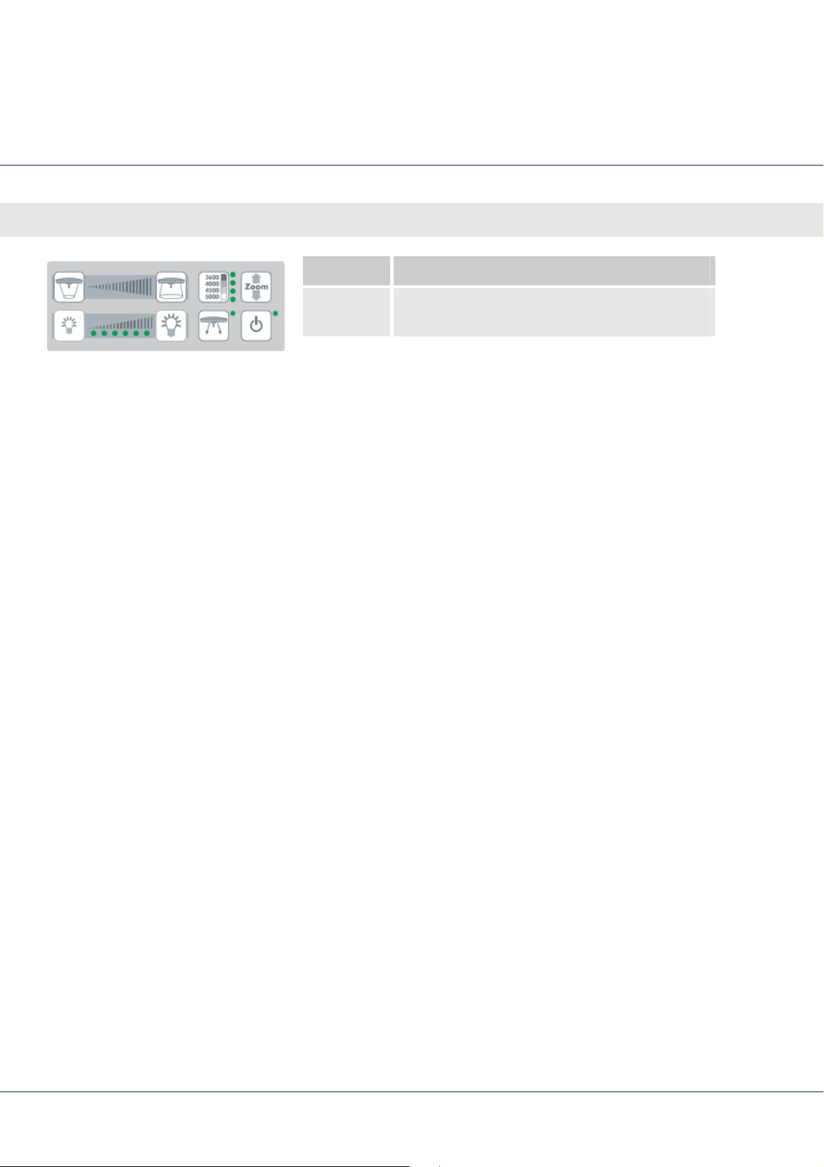
Part No. Description
81185 Key board foil with GuideLiteTM, Color Select and
ChromoVision® ECO
Fig. 27: Keyboard with GuideLiteTM, Color
Select and ChromoVision® ECO
60
Page 61
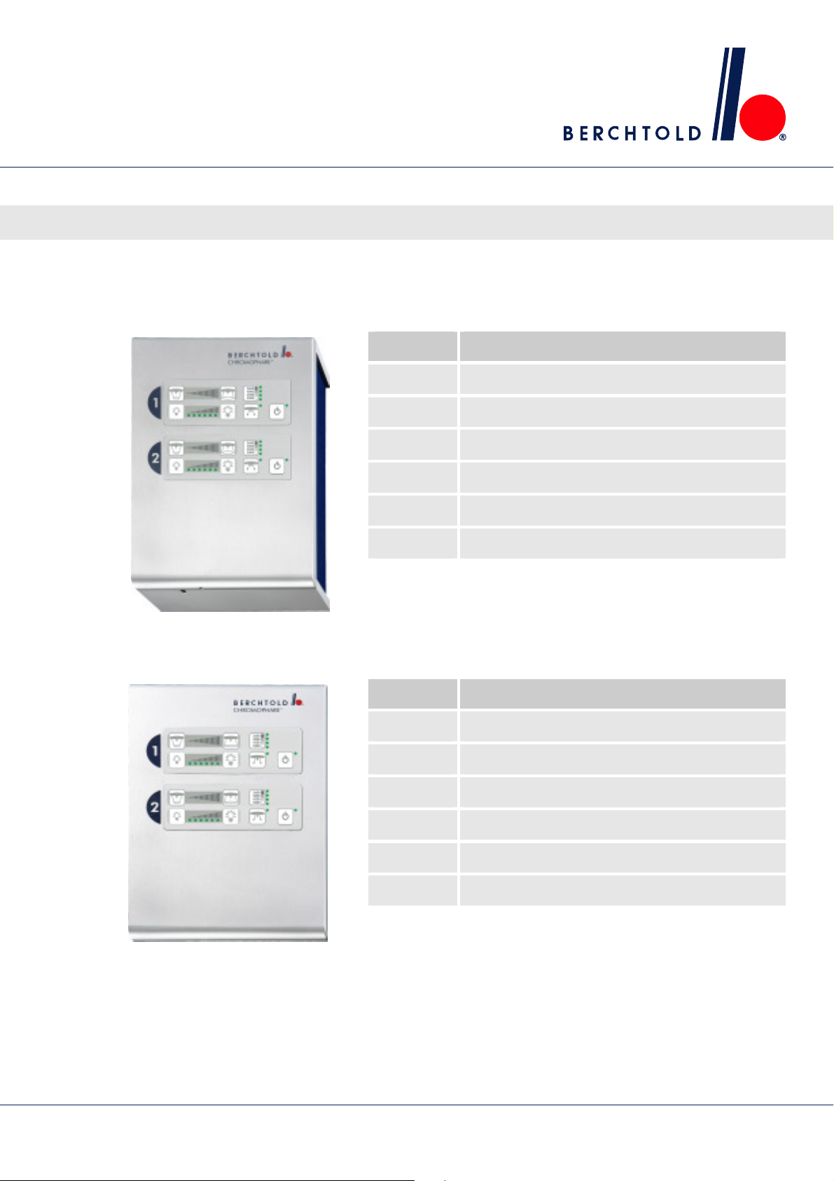
10 Wallbox
10.1 Flush mounted
LED surgical lights, single and combination lights CHROMOPHARE® E 778, E 668, E 558
Wallbox
Part No. Description
81152 Single LED with Communication Interface
81153 Single LED w/o Communication Interface
81158 Double LED with Communication Interface
81159 Double LED w/o Communication Interface
81164 Triple LED with Communication Interface
Fig. 28: Flush mounted wallbox
10.2 Surface mounted
Fig. 29: Surface mounted wallbox
81165 Triple LED w/o Communication Interface
Part No. Description
81156 Single LED with Communication Interface
81157 Single LED w/o Communication Interface
81162 Double LED with Communication Interface
81163 Double LED w/o Communication Interface
81168 Triple LED with Communication Interface
81169 Triple LED w/o Communication Interface
61
Page 62
LED surgical lights, single and combination lights CHROMOPHARE® E 778, E 668, E 558
Wallbox
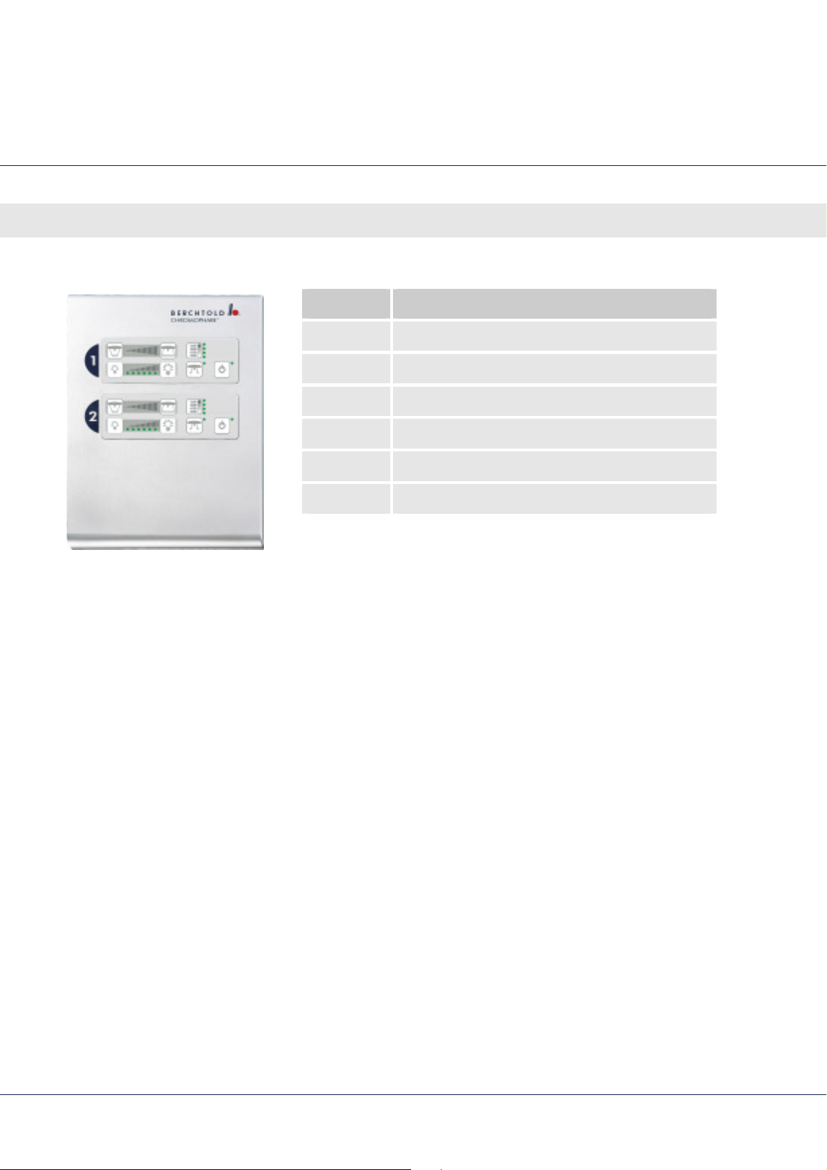
10.3 Flush mounted in tableau
Part No. Description
81154 Single LED with Communication Interface
81155 Single LED w/o Communication Interface
81160 Double LED with Communication Interface
81161 Double LED w/o Communication Interface
81166 Triple LED with Communication Interface
81167 Triple LED w/o Communication Interface
Fig. 30: Flush mounted in tableau
62
Page 63

LED surgical lights, single and combination lights CHROMOPHARE® E 778, E 668, E 558
11 Connecting the electricity
Connecting the electricity
NOTE!
Electrical installation must comply with the IEC
60364-710 European standard and the current
local standards.
Power switches and fuses must be installed by the
customer (for fuse values appendix) or the fuses
and fuse holder delivered must be used.
The cross-section of the connecting lines between
the fuses and the transformers must be at least
1.5 mm².
NOTE!
Detailed electrical plans may be requested from
technical service ( address on the inside of the
back cover of the manual).
NOTE!
Pay attention to the fuse ratings on the fuse
holders!
NOTE!
Fuses must be UL and IEC 60127 approved.
63
Page 64
LED surgical lights, single and combination lights CHROMOPHARE® E 778, E 668, E 558
Connecting the electricity
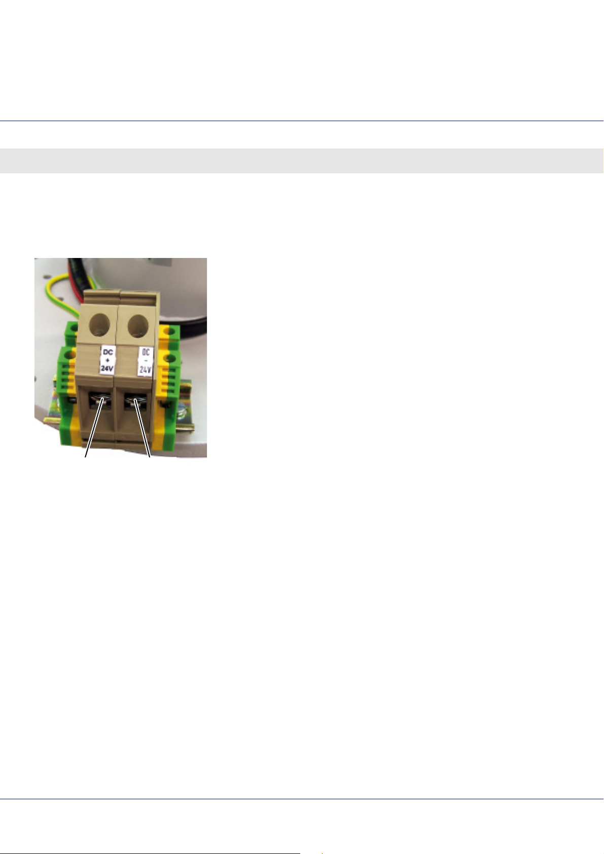
11.1 Electrical connection on the ceiling tube
DC power supply
+ 24 V DC - 24 V DC
Fig. 31 DC terminals
Use only when emergency power relays are available on site.
DC terminals (up to 36 mm2 cable cross-section)
Equipotential bonding terminals (up to 10 mm2 cable cross-
section)
Transformer and emergency power relays are installed separately
from the ceiling tube.
Combination lights have additional terminal pairs. Connect them
as well.
64
Page 65
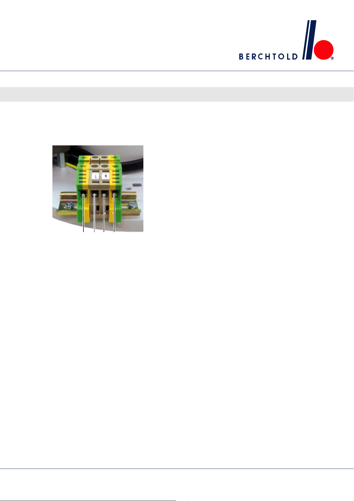
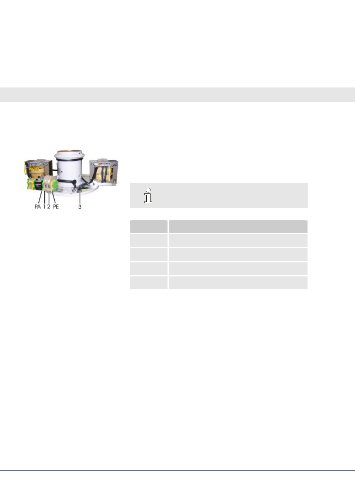
230 V AC power supply
PEPA NL
Fig. 32 Power supply terminals
LED surgical lights, single and combination lights CHROMOPHARE® E 778, E 668, E 558
Connecting the electricity
Use only when 230 V emergency power relays are available on
site.
230 V mains terminals
Transformer and filtering board have been mounted to ceiling
tube.
Connect line voltage according to the country
(also see transformer model plate) to terminal pair L and N.
Also connect PE and PA (protective conductor and equipotential
bonding).
Combination lights have additional terminal pairs. Connect them
as well.
65
Page 66
LED surgical lights, single and combination lights CHROMOPHARE® E 778, E 668, E 558
Connecting the electricity
230 V AC power supply with emergency power relays
Input voltages:
Supply voltage (L1/N)
24-28 volt DC emergency power supply
Output voltage at plug in ceiling tube:
24-28 volt DC under load (for the surgical light)
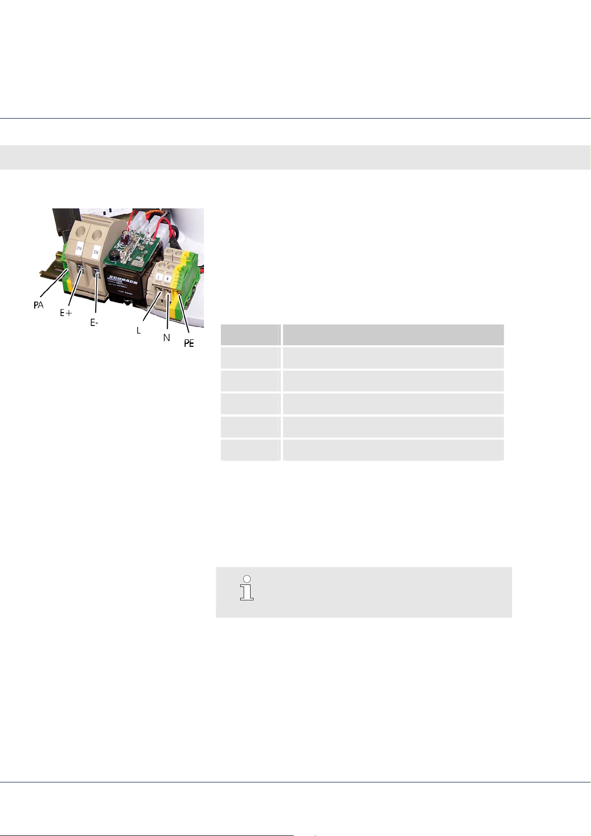
Terminal Connection
Fig. 33 Terminals for the power supply and
the emergency power supply
E+ Emergency power supply + 24-28 V DC
E- Emergency power supply – 24-28 V DC
L Mains AC
N Mains AC
PA/PE Ground
Ceiling tube of the CHROMOPHARE® surgical light with
transformer, filtering board and emergency power relay
mounted.
Combination lights have additional terminal pairs. Connect
them as well.
NOTE!
The emergency power switch-over must be
ordered separately.
66
Page 67
LED surgical lights, single and combination lights CHROMOPHARE® E 778, E 668, E 558
11.2 Electrical connections on the mounting plate
Mounting plate
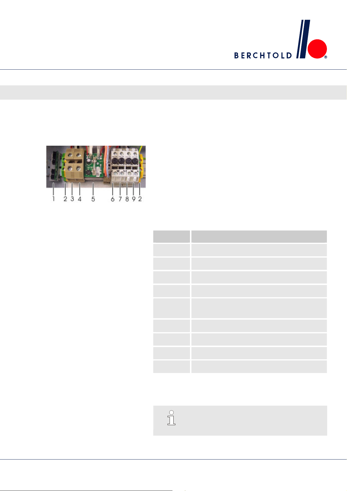
Fig. 34 Mounting plate terminals with
filtering board
Use only when emergency power relays are available on site.
Input voltages:
max. 28 volt DC or max. 26 volt AC
Output voltage:
24–28 volt DC to the surgical light
A drop in voltage on the line to the surgical light can be
compensated for only by a corresponding increase in the DC
input voltage.
Connecting the electricity
Terminal Connection
1 CAN distribution board
2 PE/PA ground
3 DC out
4 DC out
5 Emergency power switch-over relay
(with emergency power relays)
6 DC in (with emergency power relays)
7 DC in (with emergency power relays)
8 AC in
9 AC in
Combination lights require an additional mounting plate with
terminals. Connect them as well.
NOTE!
DC fuses must be installed by the customer (for
fuse ratings appendix).
67
Page 68
LED surgical lights, single and combination lights CHROMOPHARE® E 778, E 668, E 558
Connecting the electricity
26 V AC and max. 28 V DC power supply
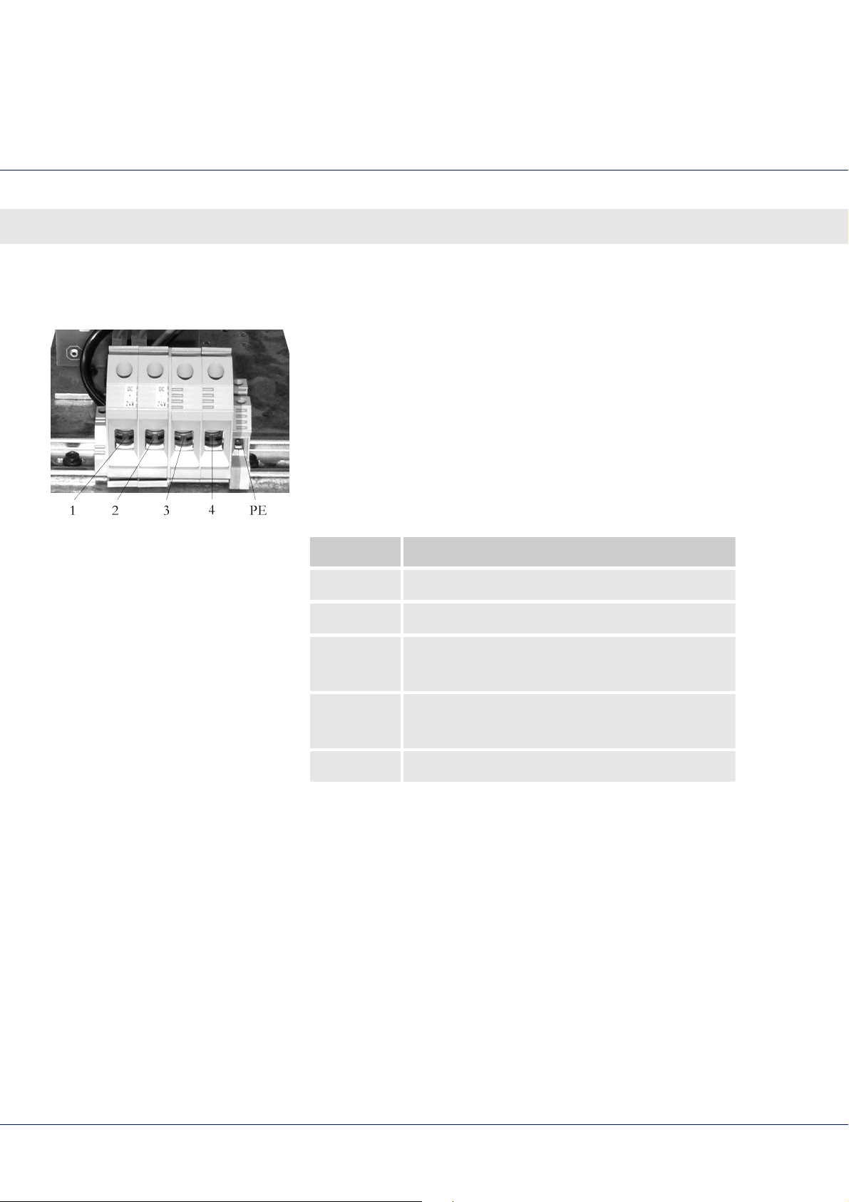
Fig. 35 Mounting plate terminals with
filtering board
Use only when emergency power relays are available on site.
Input voltages:
max. 28 volt DC or max. 26 volt AC
Output voltage:
24–28 volt DC to the surgical light
A drop in voltage on the line to the surgical light can be
compensated for only by a corresponding increase in the DC
input voltage.
Terminal Connection
1 Output + 24–28 V DC
2 Output - 24–28 V DC
3 Input max. + 28 V DC
Input max. 26 V AC
4 Input max. - 28 V DC
Input max. 26 V AC
PE Ground
Combination lights require an additional mounting plate with
terminals. Connect them as well.
68
Page 69
LED surgical lights, single and combination lights CHROMOPHARE® E 778, E 668, E 558
11.2.1 Electrical connections for ChromoVision
Connections on ceiling flange
Connecting the electricity
camera system HD and 1 C
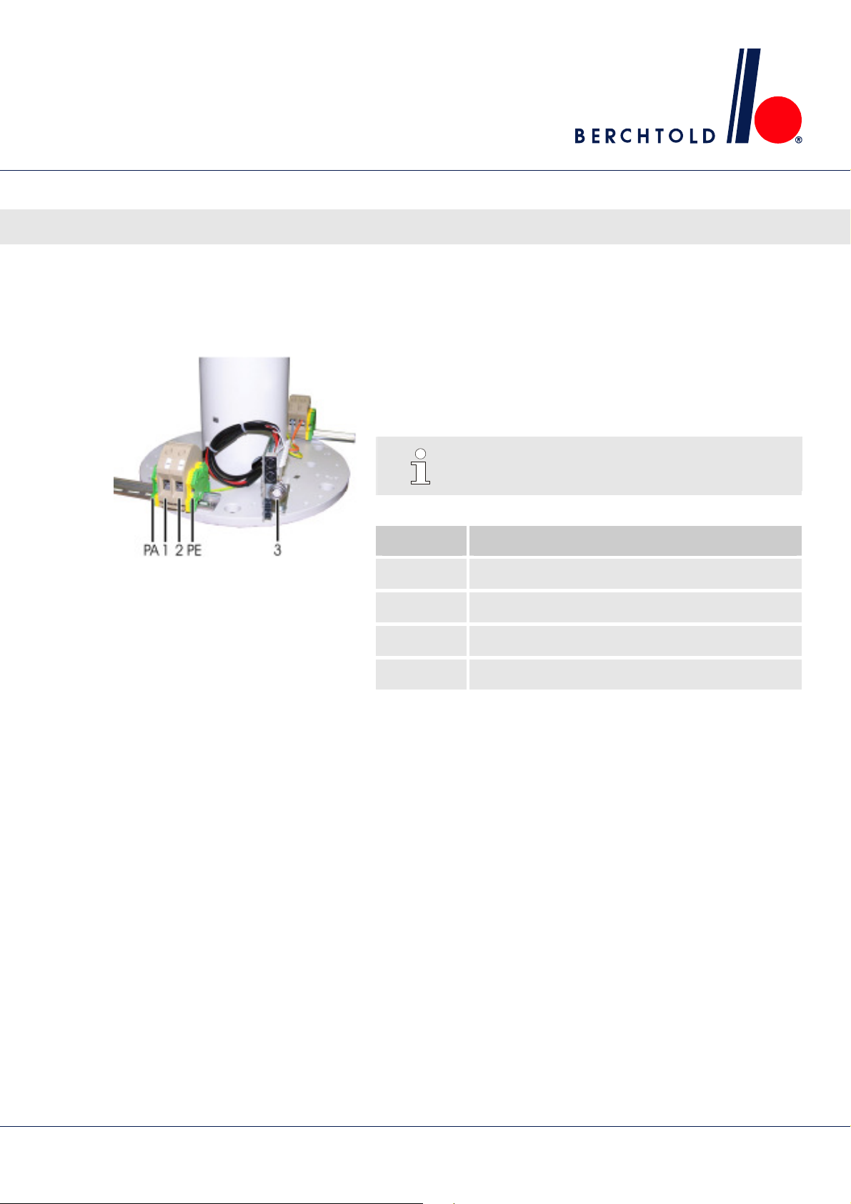
Fig. 36 Ceiling flange connections
Use only when emergency power relays are available on site.
See circuit diagram (request a copy from technical service,
inside of back cover).
NOTE!
Do not shorten the 15 m camera cable!
Terminal Connection
1 Input 24 V DC
2 Input 24 V DC
3 Camera cable connector port
PE/PA Ground
69
Page 70
LED surgical lights, single and combination lights CHROMOPHARE® E 778, E 668, E 558
Connecting the electricity
11.2.2 Electrical connections for ChromoVision
Connections on ceiling flange
ECO camera system
Fig. 37: Ceiling flange connections
Use only when emergency power relays are available on site.
See circuit diagram (request a copy from technical service,
inside back cover).
NOTE!
Do not shorten the 15 m camera cable!
Terminal Connection
1 Input 24 V DC
2 Input 24 V DC
3 Y/C socket, video
PE/PA Ground
70
Page 71
LED surgical lights, single and combination lights CHROMOPHARE® E 778, E 668, E 558
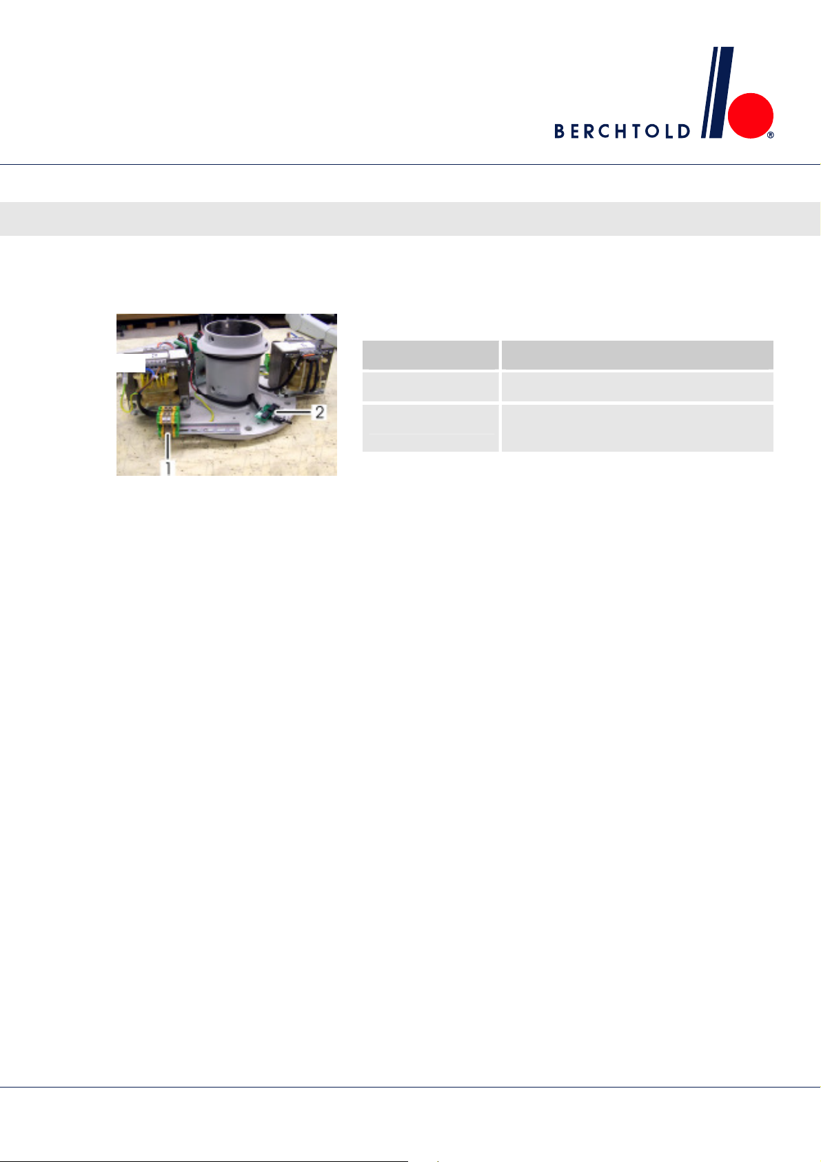
11.2.3 Electrical connections with wall control box
Connections on ceiling tube
Ceiling tube of the CHROMOPHARE® surgical light.
Position Circuit Boards
1 230 V connection
2 CAN distribution board: Connection for
Combination lights have additional terminal pairs that must also
Fig. 38 Ceiling flange connections
be connected.
Connecting the electricity
wall control box (wall box)
71
Page 72
LED surgical lights, single and combination lights CHROMOPHARE® E 778, E 668, E 558
Connecting the electricity
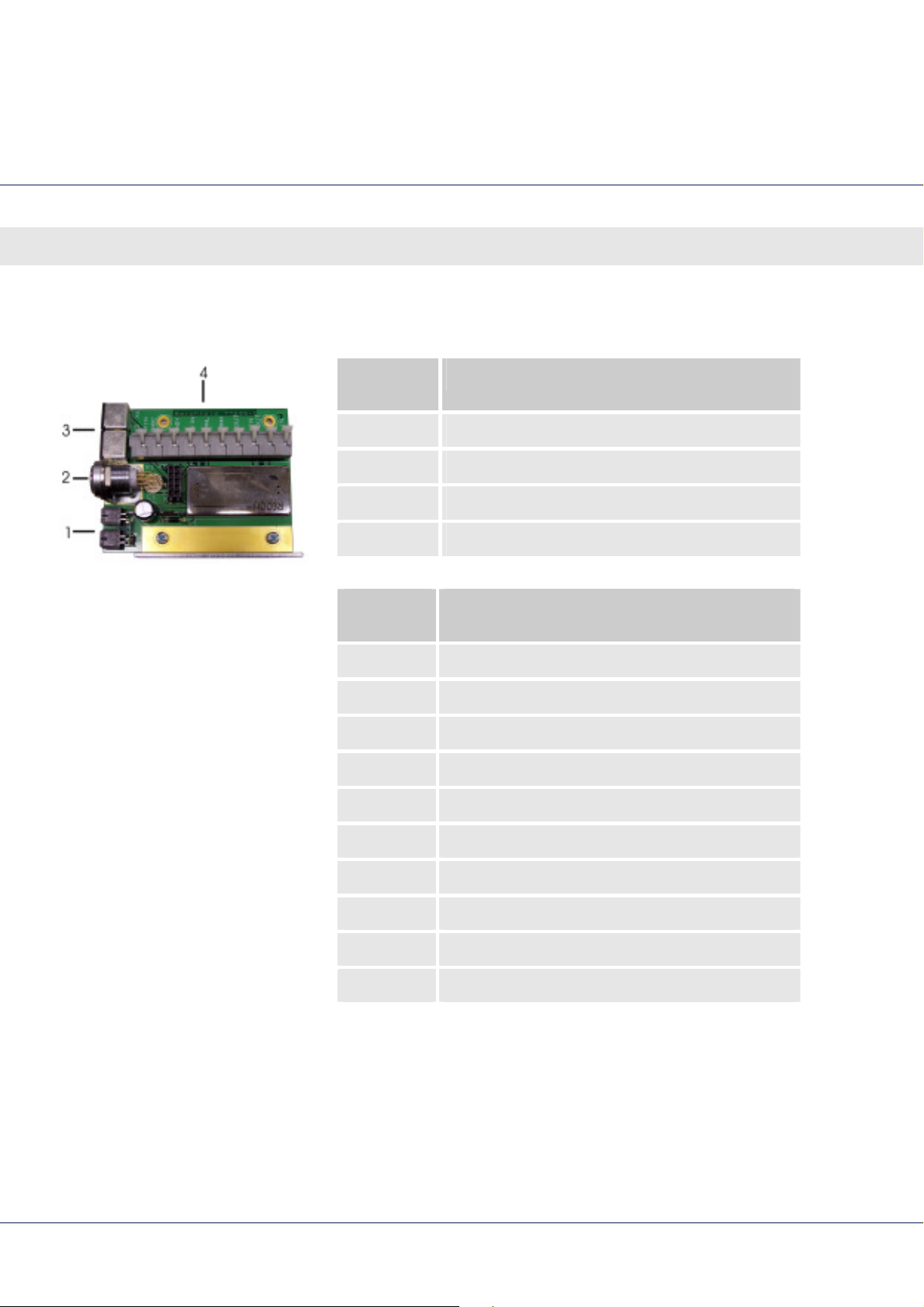
11.3 Connecting the camera distribution board
11.3.1 ChromoVision
camera system HD and 1 C
Fig. 39 Camera distribution board
Connection/
Connection
Position
1 CAN BUS
2 12-pin connection (for camera cable)
3 2x Y/C video connection
4 Terminal strip (see table for connections)
Terminal
Function
strip
C/IN Video Signal C input
GNDC Ground Video Signal C input
GNDY Ground Video Signal Y input
Y/IN Video Signal Y input
CANL CAN BUS LOW Signal
CANH CAN BUS HIGH Signal
+OUT +Ub to light head
+IN +Ub from supply
−OUT −Ub to light head
−N −Ub from supply
72
Page 73
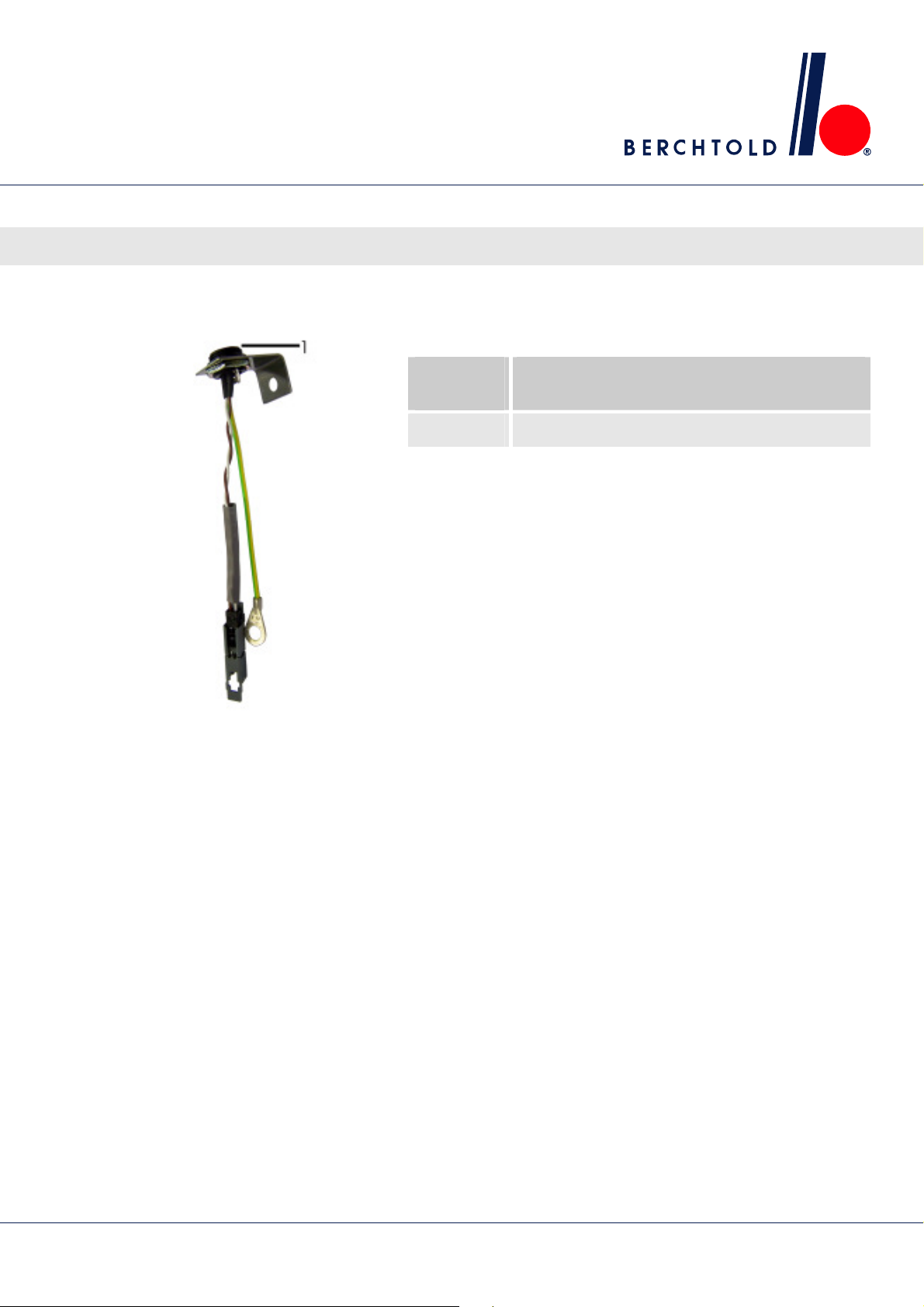
11.3.2 ChromoVision
LED surgical lights, single and combination lights CHROMOPHARE® E 778, E 668, E 558
Connecting the electricity
ECO camera system
Connection/
Position
1 Y/C socket, video
Connection
Fig. 40: ECO connector
73
Page 74
LED surgical lights, single and combination lights CHROMOPHARE® E 778, E 668, E 558
Mechanical adjustments
12 Mechanical adjustments
12.1 Diagrams
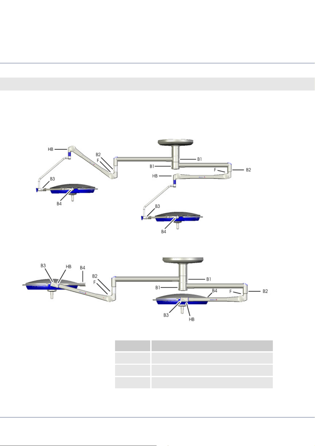
Fig. 41 Adjustment points, classic cardanic
Fig. 42 Adjustment points, flat cardanic
Abbreviation Adjustment element
B Brake screw
F Spring tension adjustment
HB Height limit
74
Page 75
LED surgical lights, single and combination lights CHROMOPHARE® E 778, E 668, E 558
12.2 Adjusting the brakes
Mechanical adjustments
NOTE!
The following steps apply to spring arms mounted
to a height adjustment tube as well as spring arms
mounted directly to the swivel arm.
Adjust the braking action of the individual joints so that the light
head stays in any given position. If the suspension arm of the
surgical light drifts, tighten or replace the appropriate brake screw.
CAUTION!
Risk of injury if braking action of joints fail!
If the brake screws are lubricated or residual
lubrication is left on them, they lose their braking
action and the articulated joints will not stop as
desired when moved.
Therefore:
– You must ensure that the brake screws are
completely free of lubricant!
– Residual lubricant on the brake screws must be
removed immediately, e.g. with petroleum
ether solvent!
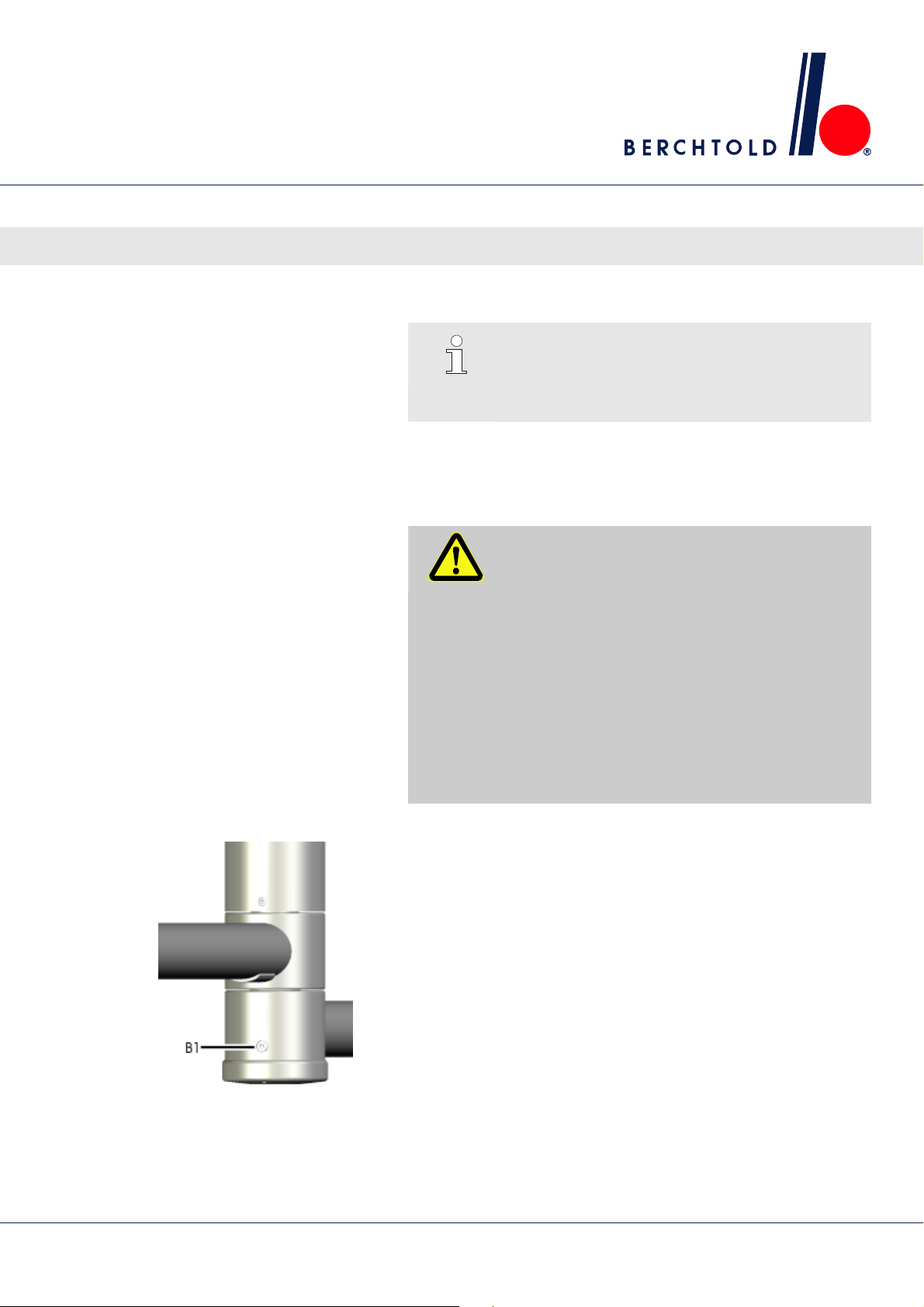
Swivel arm brakes
Use the brake screw (B1) to adjust the braking action to the
rotation of the swivel arm.
Turn counterclockwise to decrease the braking action.
Turn counterclockwise to reduce the braking action.
Fig. 43 Brake screw, B1
75
Page 76
LED surgical lights, single and combination lights CHROMOPHARE® E 778, E 668, E 558
Mechanical adjustments
Spring arm brakes
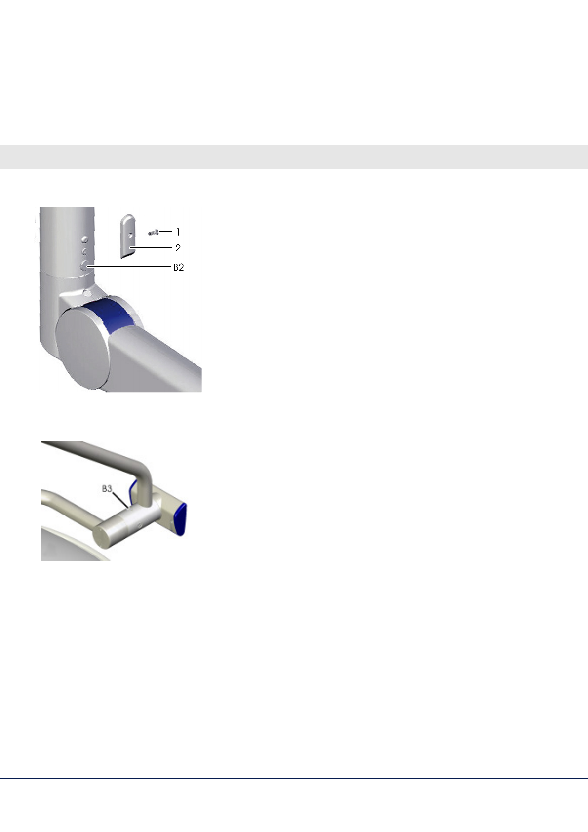
1. Loosen screw (1).
2. Remove the cover (2).
3. Use brake screw B2 to adjust the braking action to the rotation
of the spring arm:
Turn counterclockwise to decrease the braking action.
Turn counterclockwise to reduce the braking action.
4. To reattach the cover, perform steps 1-2 in reverse order.
Fig. 44 Brake screw, B2
Cardan joint brakes (classic cardanic)
Fig. 45 Brake screw, B3 (A.C.)
Use the brake screw (B3) to adjust the braking action of the
cardan joint:
Turn counterclockwise to decrease the braking action.
Turn counterclockwise to reduce the braking action.
76
Page 77
LED surgical lights, single and combination lights CHROMOPHARE® E 778, E 668, E 558
Cardan joint brakes (flat cardanic)
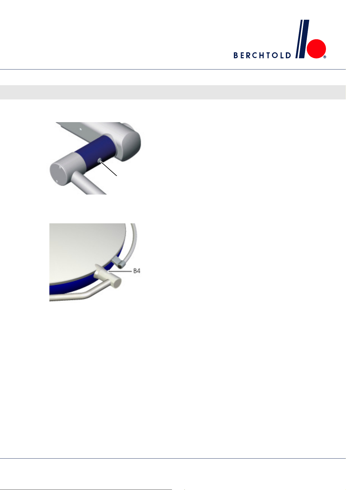
B3
Fig. 46 Brake screw, B3 (N.C.)
Light head brakes
Mechanical adjustments
Use the brake screw (B3) to adjust the braking action of the
cardan joint:
Turn counterclockwise to decrease the braking action.
Turn counterclockwise to reduce the braking action.
Fig. 47 Brake screw, B4
Use the brake screw (B4) to adjust the braking action to the
rotation of the light head.
Turn counterclockwise to decrease the braking action.
Turn counterclockwise to reduce the braking action.
77
Page 78
LED surgical lights, single and combination lights CHROMOPHARE® E 778, E 668, E 558
Mechanical adjustments
12.3 Adjusting the height stop and counterweight
Spring arm height stop
(classic cardanic)
NOTE!
For a low ceiling, you can adjust the spring arm
height down to a horizontal position.
CAUTION!
Risk of injury from uncontrolled moving parts!
The spring arm is under a high level of tension. The
spring arm can move erratically of its own accord
and cause injury.
Therefore:
– Do not set the adjustment screw until assembly
1.
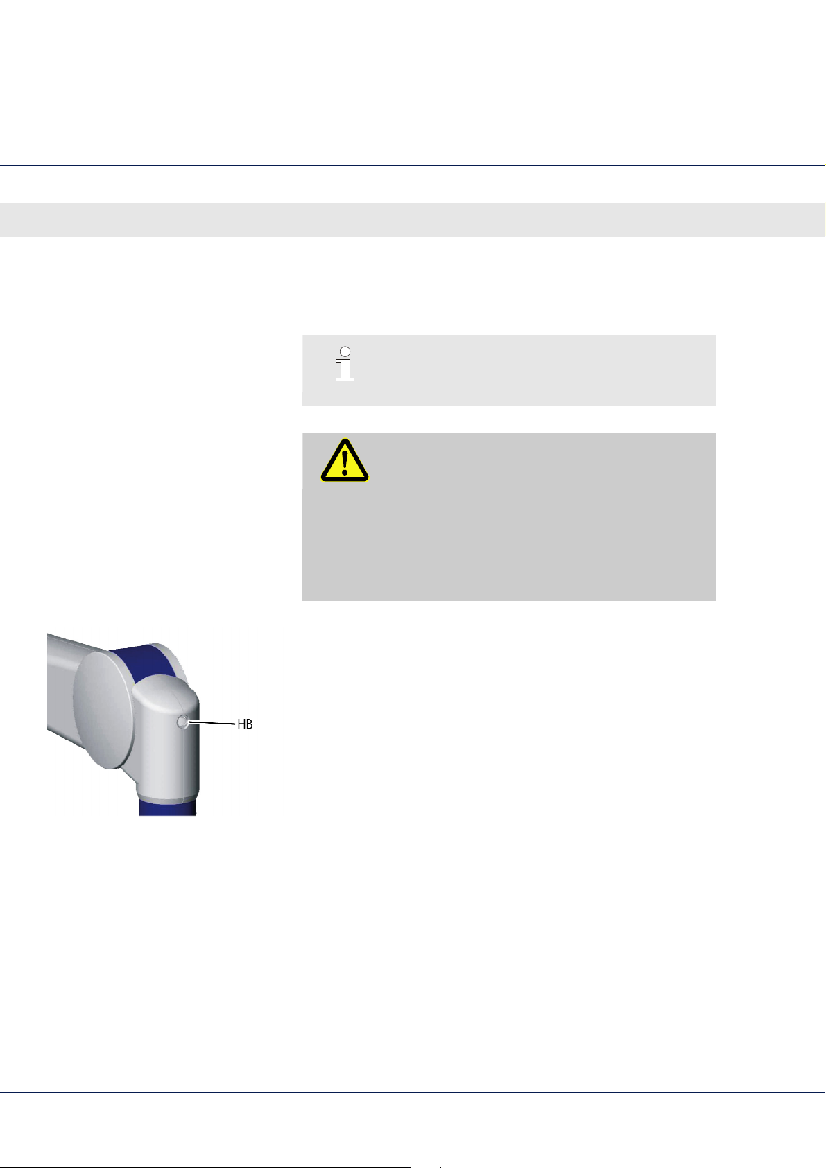
Remove the end cap using a small screw driver.
is complete.
The HB adjustment screw for the height stop is beneath the
end cap.
2.
Put the spring arm in a horizontal position.
3.
Use the HB adjustment screw to adjust the height limit:
Turn clockwise to reduce the height.
Turn counterclockwise to increase the height.
4.
Replace the end cap.
Fig. 48 Adjustment screw, HB
78
Page 79
LED surgical lights, single and combination lights CHROMOPHARE® E 778, E 668, E 558
Spring arm height stop (flat cardanic)
Mechanical adjustments
Special tools
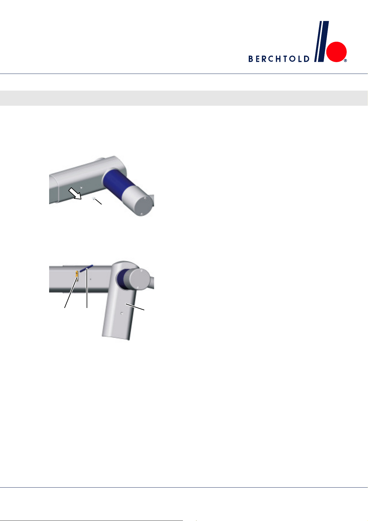
Fig. 49 Cover
1
Steel pin, ∅ 4 mm
1.
Remove the mounting screw (1).
2.
Pull off the cover in the direction of the arrow.
3.
Turn the cover (1) down as pictured.
4.
Position the spring arm so the ring nut (2) appears in the slit.
5.
Use the steel pin (3) to rotate the ring nut until the desired
height limit is reached:
Turn clockwise to reduce the height.
Turn counterclockwise to increase the height.
6.
1 2 3
To reattach the cover, perform steps 1-4 in reverse order.
Fig. 50 Ring nut
79
Page 80
LED surgical lights, single and combination lights CHROMOPHARE® E 778, E 668, E 558
Mechanical adjustments
Spring arm counterweight
1
2
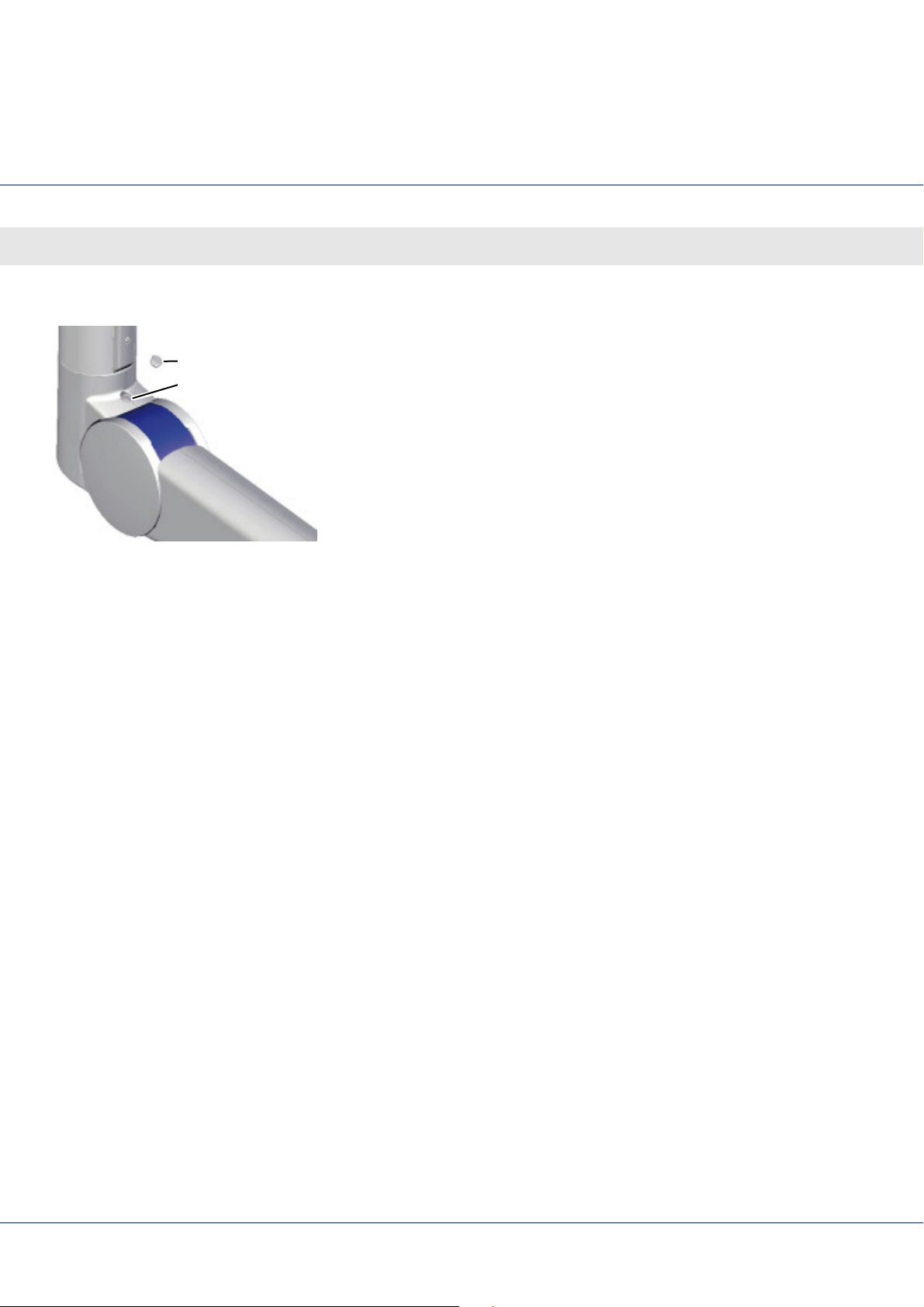
Fig. 51 Screw for adjusting spring tension
1.
Remove the end cap (1) with a small screw driver.
The counterweight adjusting screw, F (2), is located under the
end cap.
2.
Put the spring arm into a position as close to horizontal as
possible so that adjusting screw F (2) is easy to access with a
ball-head Allen wrench.
3.
Use adjustment screw F to adjust the spring tension:
Turn clockwise to increase the spring tension.
Turn counterclockwise to reduce the spring tension.
4.
Replace the end cap.
80
Page 81

LED surgical lights, single and combination lights CHROMOPHARE® E 778, E 668, E 558
13 Maintenance and inspection
13.1 Safety
Personnel
Personal protective equipment
Basic information
Unless otherwise indicated, the maintenance tasks described
here are performed by the operator.
Some maintenance work may be done only by specially
trained technicians or the manufacturer; these tasks are
marked accordingly.
Only skilled electricians may perform any electrical work.
Maintenance and inspection
NOTE!
The individual warning notices in this section
indicate the protective equipment to be worn for
each task.
WARNING!
Risk of injury due to improperly performed
maintenance!
Improper maintenance can cause severe injury or
damage.
Therefore:
– Before beginning installation, ensure there is
adequate space.
– If components are removed, be sure to note
the correct installation; correctly reinstall all
fasteners and observe correct torques.
81
Page 82

LED surgical lights, single and combination lights CHROMOPHARE® E 778, E 668, E 558
Maintenance and inspection
13.2 Cleaning, disinfection and sterilization
General cleaning and disinfection
The cleaning and disinfection of the operating light shall only be
made by a hygiene specialist or the person who is instructed by
the hygiene specialist.
Only chemicals which have been tested in terms of material
compatibility and released by BERCHTOLD shall be used. Special
care is necessary for the choice of the chemical product as well
as their concentration.
If the each current list, which can be view on the internet and is
also available on request ( back side of cover), does not include
a disinfectant or detergent, it shall not be used, since functional
components can be modified or damaged.
Prior to actual disinfection, perform a thorough cleaning to
remove any visible impurities, such as blood, etc.
Do not use any sharp, pointed or abrasive objects during
cleaning, as there is always a risk of damaging the surface.
Damaged surfaces become exposed to chemical substances
during subsequent cleaning or disinfection. This damages the
surface.
Therefore, only a soft brush and a mild cleaning agent (or a
cleaning disinfectant) are allowed for cleaning heavy and
stubborn impurities. When all visible impurities are gone,
disinfection is performed.
NOTE!
Any implied warranty claim terminates when these
guidelines are ignored.
NOTE!
The implied warranty is only valid for undamaged
surfaces!
82
Page 83

LED surgical lights, single and combination lights CHROMOPHARE® E 778, E 668, E 558
Maintenance and inspection
Recommended cleaners and
disinfectants
Wet disinfection instructions for
support system, light head and wall
control unit
NOTE!
Current recommendations:
Surface disinfectants and detergents for
manual preparation.
Disinfectants and detergents for automatic
preparation
can be viewed on the internet and are also
available on request (
back side of cover
).
NOTE!
The operator should refer to recognized
standards for hygiene and disinfection.
When cleaning, only a thin liquid film may be applied.
After wiping, a thin, coherent, moisturizing film is - from the
perspective of microbiological efficiency - sufficient; the surface
does not have to be "drenched".
In order to prevent a build-up of disinfectant material, clean
regularly with a mild all purpose cleaner.
Regularity depends on the frequency of the treatment. We
recommend that cleansing be performed at least once a month.
Clean the surgical lights with a damp cloth only, not a wet cloth.
83
Page 84

LED surgical lights, single and combination lights CHROMOPHARE® E 778, E 668, E 558
Maintenance and inspection
CAUTION!
Improper use of disinfection products can lead
to product damage!
Not following or adhering to the information and
instructions in this chapter can result in product
damage!
It also voids any implied warranty claims!
Therefore:
– When cleaning and disinfecting, make sure
that no liquid penetrates the light head or
support system components.
– The surface disinfectants may only be used in
the concentration prescribed by the manufacturer.
– The use of NATRONLAUGE can cause surface
changes on coated aluminum components
and impair the service life of the product.
– If the surface disinfectant is used incorrectly,
such that a large amount of liquid remains on
the surface, it will cause increased coating
dissolution because the product is continually
"shifted" around the surface but never
removed. In case of an increased layer
composition of surface disinfectant, it must be
thoroughly cleansed.
84
Page 85

LED surgical lights, single and combination lights CHROMOPHARE® E 778, E 668, E 558
Maintenance and inspection
– Due to possible damage to the materials, no
solutions are suitable that are based on
halogen-splitting bonds, strong organic acids
and oxygen-splitting bonds, solvents, fuel or
other.
– In order to avoid damages to the stainless steel
parts, only use disinfectants without chlorides or
halogenoids.
– Avoid contact between aldehyde and amino
products.
Therefore, especially if an amino-based
product was used previously, before applying
the aldehyde-based disinfectant for the first
time, an intermediate cleaning step has to be
performed. This is very important because
disregarding this step may result in residue no
longer being able to be removed.
– With regard to the microbiological
effectiveness, please contact the
manufacturer of the disinfectant
85
Page 86

LED surgical lights, single and combination lights CHROMOPHARE® E 778, E 668, E 558
Maintenance and inspection
Handle sleeves,
manual disinfection
Handle sleeves,
thermal preparation
Disinfect the handle sleeves as follows:
Alcohol, QAV or aldehyde-based disinfectant.
After cleaning, make sure to completely rinse the sleeve with
water to remove any residue.
CAUTION!
Incorrect manual disinfection causes product
damages!
Not following or adhering to the instructions listed
can result in product damage!
It also voids any implied warranty claims!
Therefore:
– Avoid dipping in enzyme-based cleaner for
long periods.
The handle sleeves are made of heat- and impact-resistant
plastic.
Prepare the handle sleeves as follows:
Use alkaline-based cleaner without active chlorine
Neutralize with acidic neutralizer
The handle sleeves can be machine cleaned via
thermodisinfection at temperatures of up to 93° C for 10 minutes.
86
Page 87

LED surgical lights, single and combination lights CHROMOPHARE® E 778, E 668, E 558
Maintenance and inspection
Handle sleeves, sterilizing
Clean and disinfect handle sleeves in the usual way before
sterilization.
The handle sleeves are placed in a suitable sterilization packaging
(one-time sterilization packaging, e.g. film/paper sterilization bags;
single or double packaging) and sterilized.
The handle sleeves can be steam sterilized. The recommended
parameters are:
121°C/1.3 bar; 25 to 30 minutes (standard)
134°C/ ca. 3 bar; 3 minutes (standard)
134 °C/2-3 bar; 18 minutes (special cases)
When loading the autoclave, make sure the open end of the
sleeve is pointing down. Allow sufficient space around each
handle sleeve and do not allow them to come in contact with
any other items being sterilized.
CAUTION!
Incorrect use of disinfectants can cause product
damages!
Not following or adhering to the instructions listed
can result in product damage!
It also voids any implied warranty claims!
Therefore:
– Hot air, ethylene oxide, formaldehyde and low-
temperature plasma sterilization are not
permitted.
CAUTION!
Limited warranty on handles!
Sterilizable handles are subject to natural wear.
Therefore:
– It must be pointed out that a normal life time of
approx 100 cleaning cycles is possible.
– Damaged handles must not be used.
87
Page 88

LED surgical lights, single and combination lights CHROMOPHARE® E 778, E 668, E 558
Maintenance and inspection
13.3 Maintenance schedule
The following sections describe the maintenance work required for
optimal and trouble-free operation.
If you have any questions on maintenance tasks and intervals,
contact BERCHTOLD (
Interval Maintenance task Who should perform
service address on inside back cover
).
Daily, before each
General function tests Operator
use
As needed Changing LED modules BERCHTOLD/
authorized company
As needed Change on-site mains fuses Electrical technician
Annually General maintenance in accordance with
maintenance scope
BERCHTOLD/
authorized company
88
Page 89

LED surgical lights, single and combination lights CHROMOPHARE® E 778, E 668, E 558
13.4 Maintenance
13.4.1 Function tests before each use
13.4.2 LED modul replacement
To be completed by the operator.
Each day, before using the CHROMOPHARE lights, perform the
function tests described at the beginning of the
section.
Performed by BERCHTOLD or a company authorized by
BERCHTOLD.
Maintenance and inspection
Operation
CAUTION!
Property damage due to unauthorized
replacement of LED modules!
If defective LED modules are replaced by
insufficiently qualified persons, significant damage
to property can result.
Any and all implied warranty claims will also be
invalidated by non-compliance!
Therefore:
– LED modules may only be replaced by
BERCHTOLD or a company authorized by
BERCHTOLD.
Numbering of the LED modules begins at the side shaft
bearing counted clockwise
Fig. 52 Overview LED modules
89
Page 90
LED surgical lights, single and combination lights CHROMOPHARE® E 778, E 668, E 558
Maintenance and inspection
NOTE!
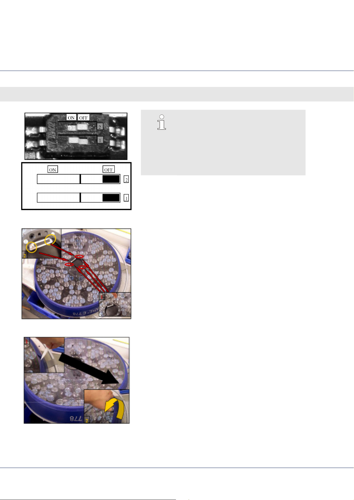
CAN-Bus end of line resistance:
The end of line resistance allows an interface
free communication between the CAN-Bus
components. The resistor (DIP switch 2) on
the first and the last module within a light
Fig. 53 DIP switch on LED modul
head must be switched on.
Fig. 54 Remove screws
1.
Remove the three screws fixing the black plastic ring
although remove the screws fixing the interface plug on
the lower glass holder.
2.
Use a acuate tool to lift the silicone seal to remove the
glass.
3.
Carefully remove the glass.
Fig. 55 Lift silicone ring, remove glass
90
Page 91
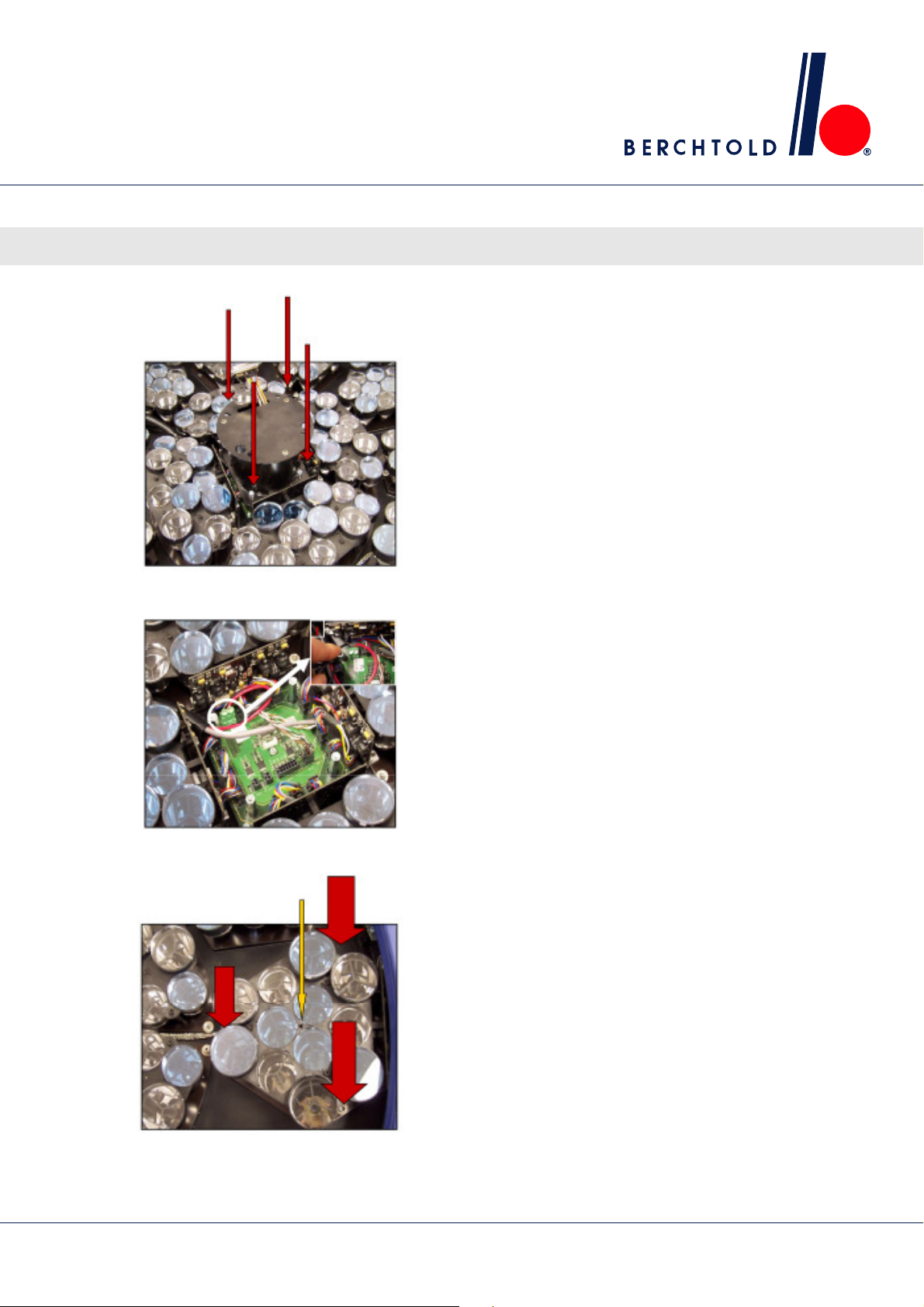
Fig. 56 Remove screws
LED surgical lights, single and combination lights CHROMOPHARE® E 778, E 668, E 558
Maintenance and inspection
4.
Remove the four screws shown by the arrows.
Fig. 57 Disconnect power supply
5.
Disconnected the power supply on the junction board.
6.
The LED module is finished with three hexagonal socket
screws (see red, fat arrowos) and a grub screw (see
yellow, narrow arrow) remove the hexagonal socket
screws completely and undo the grub screws.
The module is now free.
Fig. 58 Undo LED modules
91
Page 92
LED surgical lights, single and combination lights CHROMOPHARE® E 778, E 668, E 558
Maintenance and inspection
7.
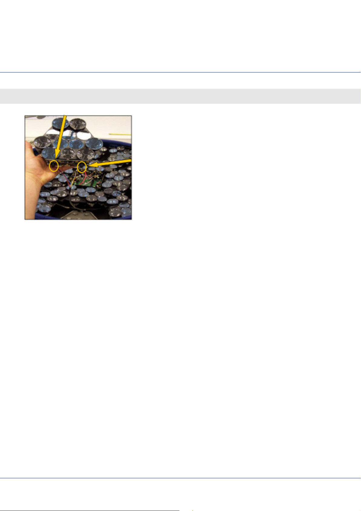
Pull out the LED module and disconnect the two plugs on
the LED control boards (see arrows).
Fig. 59 Screw for adjusting spring tension
8.
Connect the new LED module and put everything back
together.
92
Page 93

LED surgical lights, single and combination lights CHROMOPHARE® E 778, E 668, E 558
13.4.3 Replacing (on-site) fuses
Maintenance and inspection
To be performed only by a skilled electrician.
DANGER!
Risk of death from electrical current!
Touching live electrical components is life
threatening. Damage to insulation or individual
components can cause fatal injury.
Therefore:
– Electrical work is to be performed by skilled
electricians only.
Both the mains and emergency power fuses are located in an
external control cabinet for easy replacement in the event of
failure.
The fuse values are listed in the
Appendix
.
93
Page 94
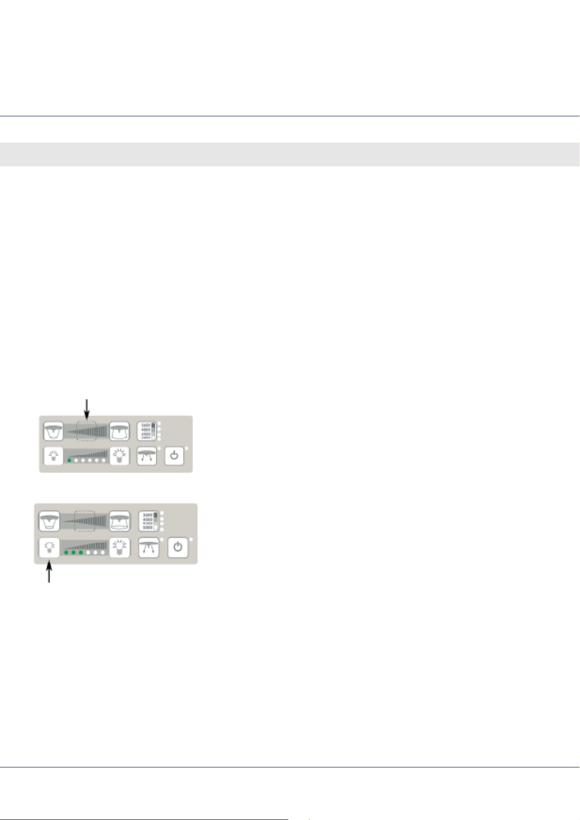
LED surgical lights, single and combination lights CHROMOPHARE® E 778, E 668, E 558
Service Menu
14 Service Menu
Basic information
Fig. 60: Service button
The Service menu is implemented as a part of the keypad
software and is activated via the Service button. The individual
LEDs of the brightness display help to distinguish between the
various menu items. In the main menu the Brighter and Darker
buttons are used to switch through the different positions. For
activating a position the Standby button is used. In the submenus
the Brighter button is used to raise the adjustments while the Darker
button is used to decrease the adjustments. In order to exit a
submenu without executing the function, the Service button is
used to cancel. Thereafter, menu item one from the main menu
is selected.
To get from a submenu to main menu press the Service button for
a short time leave the service menu by pressing the Service button
for about 3 seconds.
1.
In order to actuate the Service menu, the
Service button
to be pressed for more than 3 seconds until the first LED of
the brightness display
lights up green
.
has
2.
By pressing the
item 3. This is displayed by the
Darker
button numerous times, select menu
lighting
three LEDs of the
brightness display.
Fig. 61: Menu item 3
94
Page 95
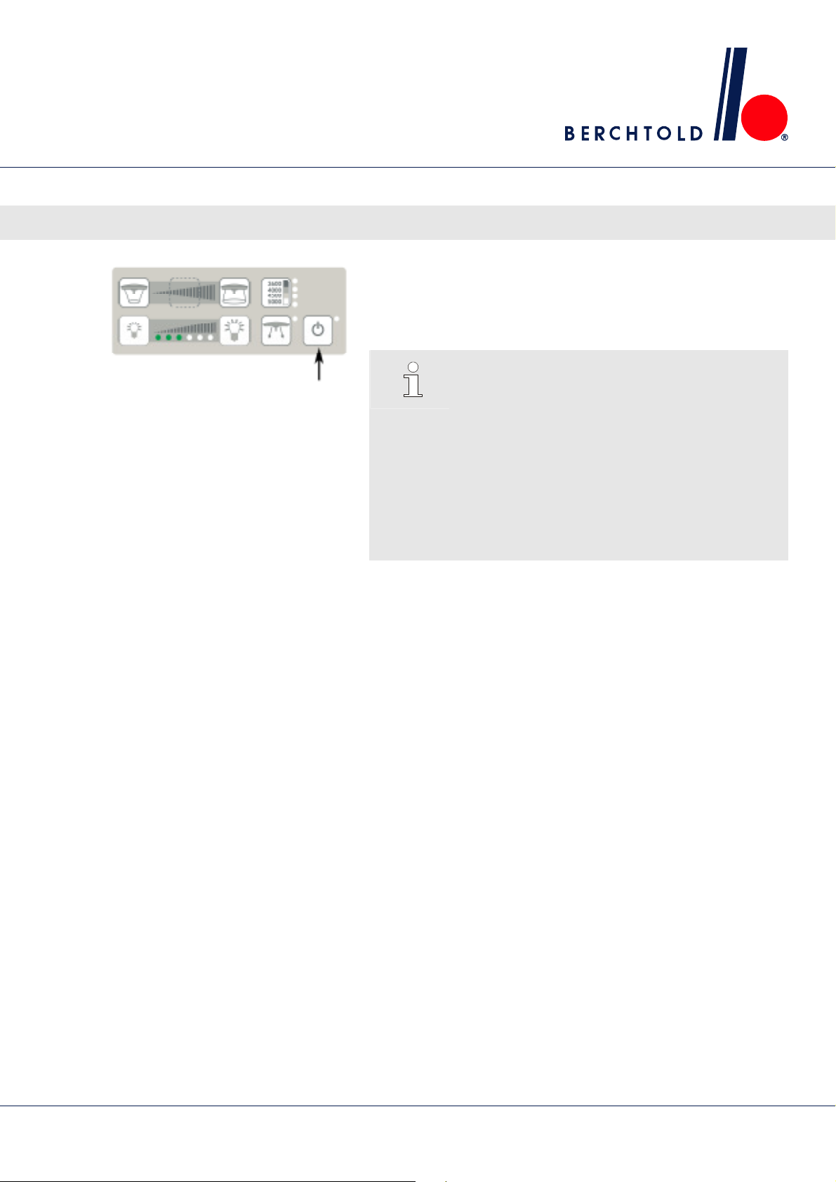
LED surgical lights, single and combination lights CHROMOPHARE® E 778, E 668, E 558
Service Menu
3.
By pressing the
is confirmed.
Thus the address appointed via the DIP-switches on the keypad
PCB will be send to all connected modules.
Standby
button, menu item 3
Fig. 62: Confirming menu item 3
NOTE!
The light head which is about to be addressed
must not be connected with another light head
via CAN-Bus.
For dual control lights the wall control must be
addressed manually first.
For wall control lights all light heads not about to
be addressed must be disconnected from CANBus at the swivel arms. The addressing is done via
wall control.
95
Page 96

LED surgical lights, single and combination lights CHROMOPHARE® E 778, E 668, E 558
Appendix
15 Appendix
15.1 Consumables
Item
Handle sleeve, standard (1 piece) CZ 4990604
Part No.
Handle sleeve for ChromoVision HD, 1 C and ECO (1 piece)
CZ 4990704
Handle sleeve, small protection collar (1 piece) CZ 4990904
96
Page 97

LED surgical lights, single and combination lights CHROMOPHARE® E 778, E 668, E 558
Appendix
- NOTES -
97
Page 98
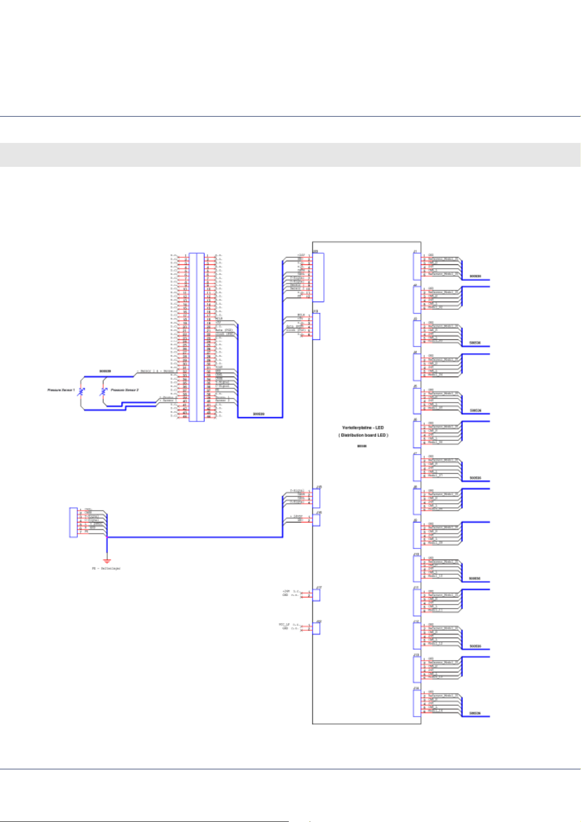
LED surgical lights, single and combination lights CHROMOPHARE® E 778, E 668, E 558
Appendix
15.2 Diagrams
15.2.1 CHROMOPHARE
E 778
Fig. 63 Diagram CHROMOPHARE E 778
98
Page 99
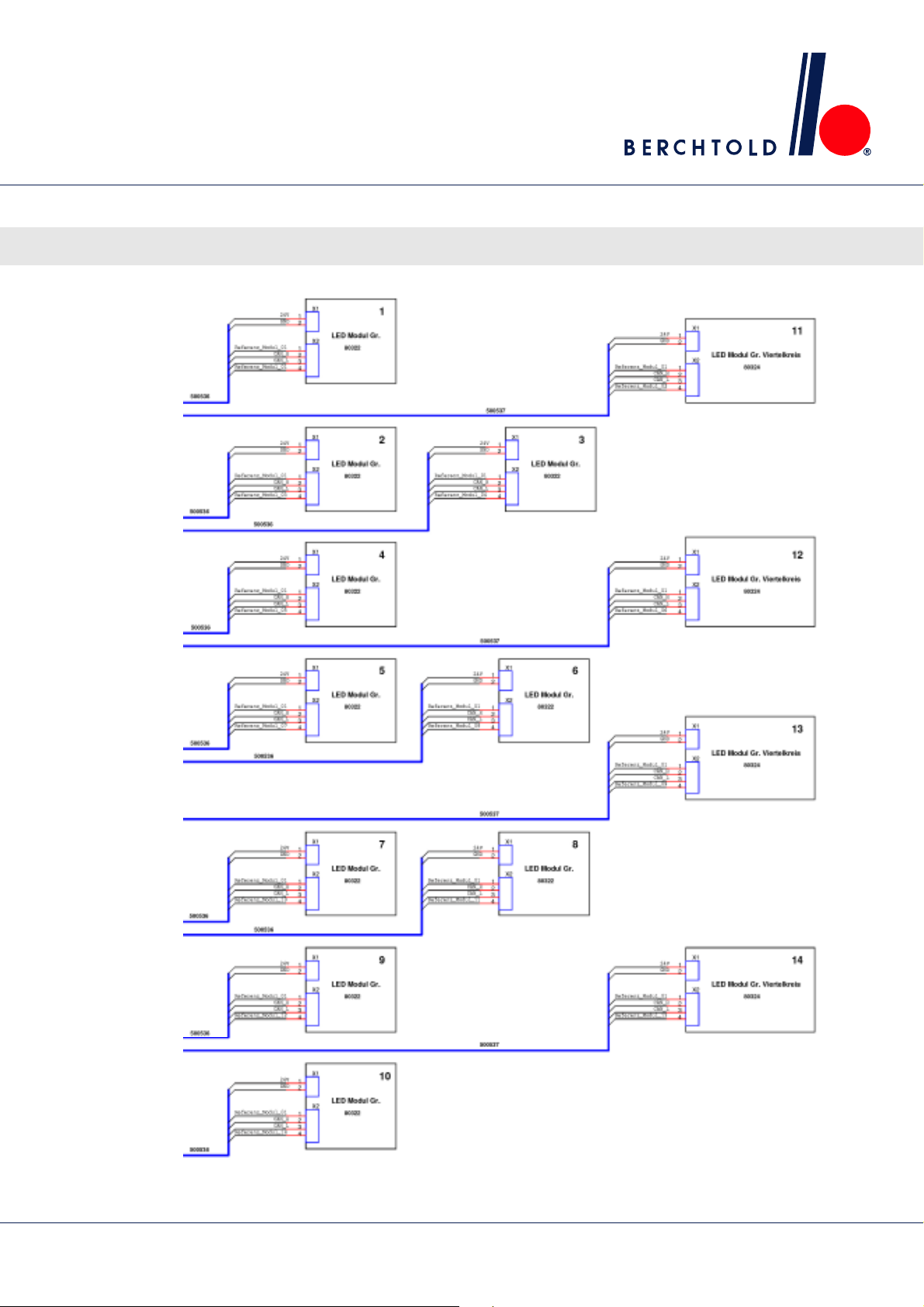
LED surgical lights, single and combination lights CHROMOPHARE® E 778, E 668, E 558
Appendix
Fig. 64 Diagram CHROMOPHARE E 778
99
Page 100
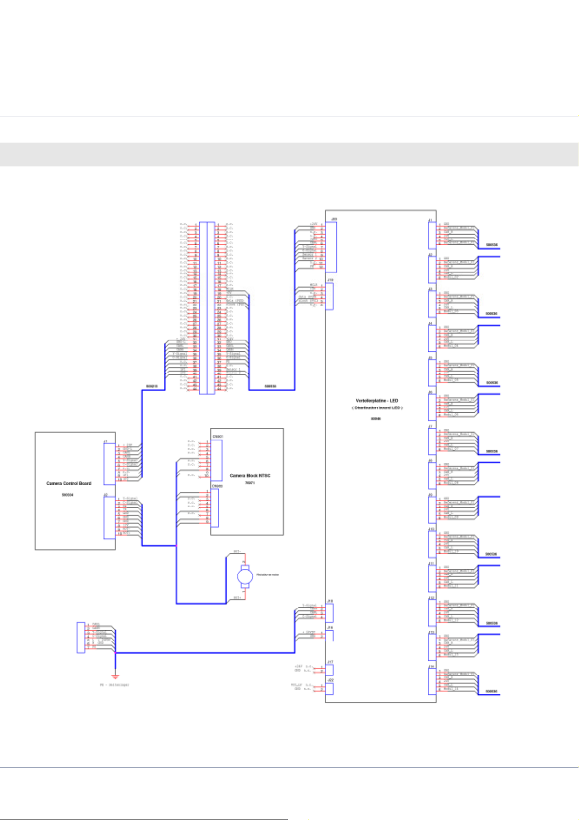
LED surgical lights, single and combination lights CHROMOPHARE® E 778, E 668, E 558
Appendix
15.2.2 CHROMOPHARE
E 778 with ChromoVision
HD and 1 C (NTSC)
Fig. 65 Diagram CHROMOPHARE E 778 with ChromoVision HD and 1 C (NTSC)
100
 Loading...