

Page 1

CHROMOPHARE
®
D 650, D 530, D 500
D 650, D 530, D 500
Service Manual (E)
Single Light and Combination Light
Page 2

CHROMOPHARE® D 650plus, D 530plus, D 500plus, D 650, D 530, D 500 Service Manual (E)
CONTENSPAGE
6
7
7
7
7
8
8
1.General6 - 8
1.1Introduction
1.2Manufacturer’s notes
1.3General information
1.4Notes on product responsibility
1.5Incoming inspection
1.6CE certification
1.7Maintenance
2.Commissioning9 - 10
2.1Range of application9
2.2Safety information’s9
2.3Installation9
2.4Visual and performance check9
2.5Cleaning, sterilization, disinfection10
3.Operation11 - 25
3.1Components11 - 13
3.1.1CHROMOPHARE® D 650plus/650plus, D 650/650 (classic cardanic)11
3.1.2CHROMOPHARE® D 650plus/650plus, D 650/650 (flat cardanic)11
3.1.3CHROMOPHARE® D 530plus/530plus, D 530/530 (classic cardanic)12
3.1.4CHROMOPHARE® D 530plus/530plus, D 530/530 (flat cardanic)12
3.1.5CHROMOPHARE® D 500plus, D 500 (classic cardanic)13
3.1.6CHROMOPHARE® D 500plus, D 500 (flat cardanic)13
3.2Notes on operation14 - 21
3.2.1Setting the control unit functions14 - 17
3.2.1.1CHROMOPHARE® D 650plus, D 65014 - 15
3.2.1.2CHROMOPHARE® D 530plus, D 53016 - 17
3.2.1.3CHROMOPHARE® D 500plus, D 50017
3.2.2Adjusting the field size with the sterizable hand grip18
3.2.3Adjusting the field size - light field plotting model LFN
(option only D 650plus, D 650)
3.2.4Changing the sterizable hand grip18
3.2.5Changing the sterizable hand grip - light field plotting model LFN
(option only D 650plus, D 650)
3.2.6Light field plotting model LFN (option only D 650plus, D 650)19
3.3Accessories for CHROMPHARE® generation D19
3.3.1Sterilizable hand grip sleeves19
3.3.2Halogen bulbs19
3.3.2.1CHROMOPHARE® D 650plus, D 530plus, D 500plus19
3.3.2.2CHROMOPHARE® D 65019
3.3.2.3CHROMOPHARE® D 530, D 50019
3.4System variants10
3.5Options20
3.6Notes on changing lamps20 - 21
18
18
2
Page 3

CHROMOPHARE® D 650plus, D 530plus, D 500plus, D 650, D 530, D 500 Service Manual (E)
CONTENSPAGE
4.Technical Data22 - 29
4.1CHROMOPHARE® D 650plus22 - 23
4.2CHROMOPHARE® D 530plus, D 500plus24 - 25
4.3CHROMOPHARE® D 65026 - 27
4.4CHROMOPHARE® D 530, D 50028 - 29
5.Serial no. identification30
6.Spare Part List30 - 34
6.1CHROMOPHARE® D 650plus, D 65030 - 32
6.2CHROMOPHARE® D 530plus, D 500plus, D 530, D 50033 - 34
7.Transformers35 - 39
7.1CHROMOPHARE® D 650
CHROMOPHARE® D 650plus, D 530plus, D 500plus
Mounting separate from the ceiling tube, distance of transformer to ceiling tube over 20 m
7.2CHROMOPHARE® D 650plus, D 530plus, D 500plus, D 530, D 500
Mounting on the ceiling tube and separate from the ceiling tube, distance of transformer to
ceiling tube 20 m
8.Graphic spare part description40 - 60
8.1CHROMOPHARE® generation D complete40 - 46
8.2CHROMOPHARE® D 650plus, D 65046 - 48
8.3CHROMOPHARE® D 650plus, D 650 version Standard and EndoLite®49 - 50
8.4CHROMOPHARE® D 650plus, D 530plus, D 650, D 53050 - 51
8.5CHROMOPHARE® D 650plus, D 650 version Standard without EndoLite®51
8.6CHROMOPHARE® D 650plus, D 650 version light field plotting model LFN52 - 55
8.7CHROMOPHARE® D 650plus, D 530plus, D 650, D 530 version with EndoLite®55 - 56
8.8CHROMOPHARE® D 530plus, D 500plus, D 530, D 50056 - 57
8.9CHROMOPHARE® D 530plus, D 530 version Standard and EndoLite®58
8.10CHROMOPHARE® D 500plus, D 500 version Standard59 - 60
9.Test and adjustment points61 - 66
9.1Test points CHROMOPHARE® D 650plus, D 65061
9.2Test points CHROMOPHARE® D 530plus, D 500plus, D 530, D 50061
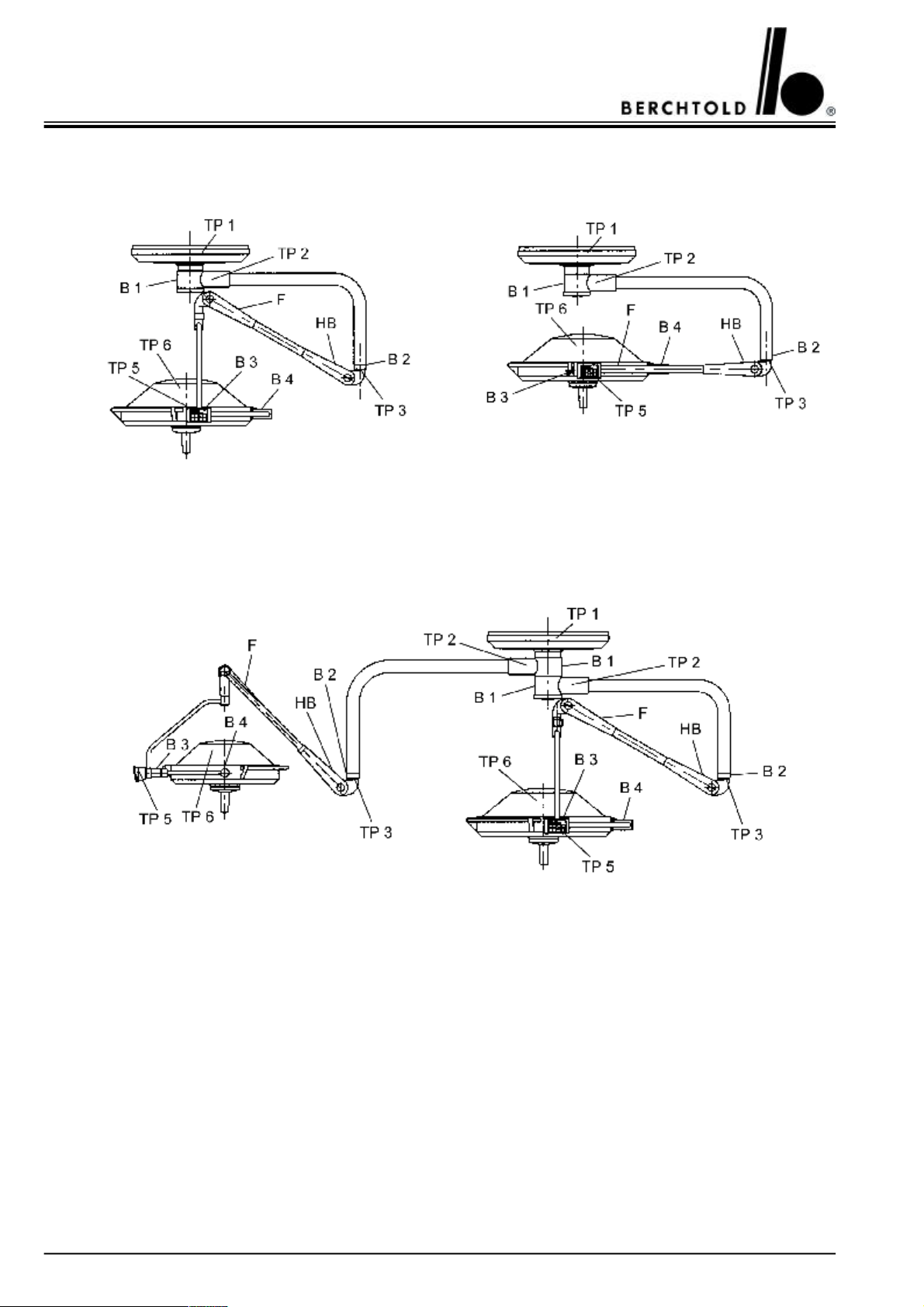
9.3.1CHROMOPHARE® D 650plus, D 650 (classic cardanic)62
9.3.2CHROMOPHARE® D 650plus, D 650 (flat cardanic)62
9.3.3CHROMOPHARE® D 650plus/530plus, D 650/530 (classic cardanic)62
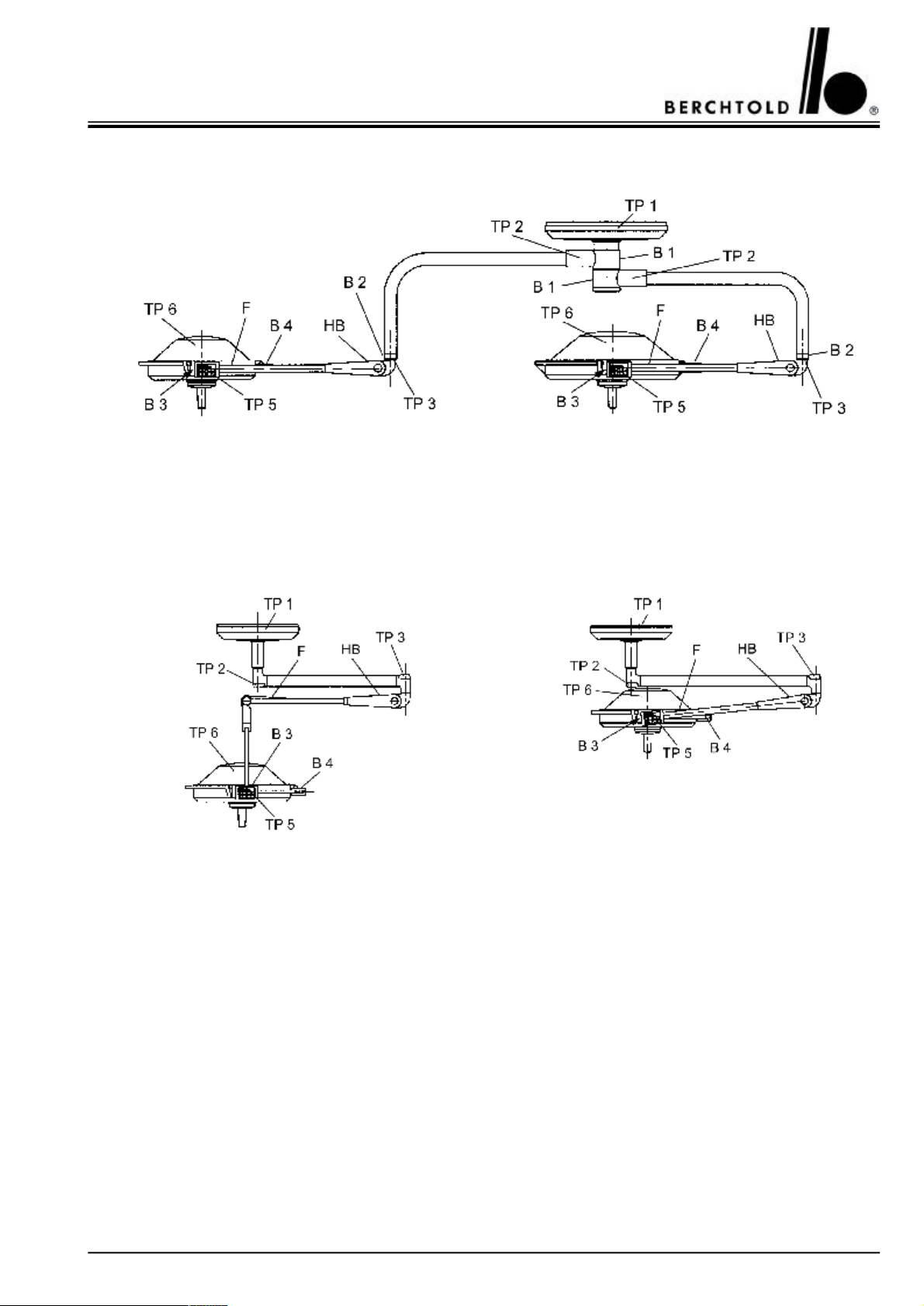
9.3.4CHROMOPHARE® D 650plus/530plus, D 650/530 (flat cardanic)63
9.3.5CHROMOPHARE® D 530plus, D 530 (classic cardanic)63
9.3.6CHROMOPHARE® D 530plus, D 530 (flat cardanic)63
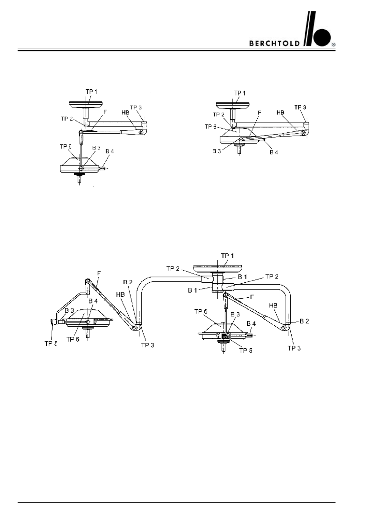
9.3.7CHROMOPHARE® D 500plus, D 500 (classic cardanic)64
9.3.8CHROMOPHARE® D 500plus, D 500 (flat cardanic)64
9.3.9CHROMOPHARE® D 530plus/530plus, D 530/530 (classic cardanic)64
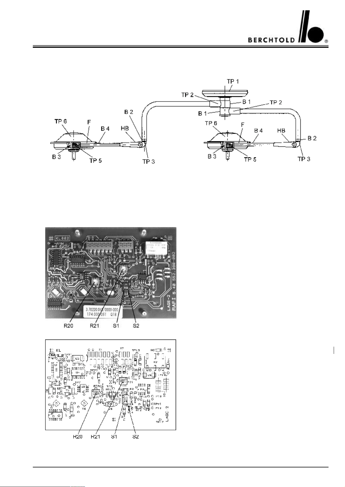
9.3.10CHROMOPHARE® D 530plus/530plus, D 530/530 (flat cardanic)65
9.4Adjustment points for halogen bulb- and EndoLite® bulb voltage66
35 - 36
37 - 38
3
Page 4

CHROMOPHARE® D 650plus, D 530plus, D 500plus, D 650, D 530, D 500 Service Manual (E)
CONTENSPAGE
10.Adjustment of weight compensation on the spring arm67 - 68
10.1CHROMOPHARE® D 650plus, D 650 (classic cardanic)67
10.2CHROMOPHARE® D 530plus, D 500plus, D 530, D 500 (classic cardanic)67
10.3CHROMOPHARE® D 650plus, D 530plus, D 500plus, D 650, D 530, D 500
(flat cardanic)
11.Adjustment of height movement on the spring arm68
12.Brake adjustments69 - 70
13.Maintenance program71
14.Wiring diagrams72 - 95
14.1CHROMOPHARE® D 650plus, D 650 Transformer mounted on the ceiling tube72
14.2CHROMOPHARE® D 650plus, D 650 Transformer and emergency relays mounted on
the ceiling tube
14.3CHROMOPHARE® D 650plus, D 650 Power supply mounted in a cut-out cabinet74
14.4CHROMOPHARE® D 650plus, D 650 Control unit in power box mounted separately
from the OR-Light
14.5CHROMOPHARE® D 650plus, D 650 Touch panel for light intensity is mounted in the
wall panel
14.6CHROMOPHARE® D 530plus, D 500plus, D 530, D 500 Transformer mounted on the
ceiling tube
14.7CHROMOPHARE® D 530plus, D 500plus, D 530, D 500 Transformer and emergency
relays mounted on the ceiling tube
14.8CHROMOPHARE® D 530plus, D 500plus, D 530, D 500 Power supply mounted in a
cut-out cabinet
14.9CHROMOPHARE® D 530plus, D 530, Control unit in power box mounted separately
from the OR-Light
14.10CHROMOPHARE® D 530plus, D 530 Touch panel for light intensity is mounted in the
wall panel
14.11CHROMOPHARE® D 650plus/650plus, D 650/650 Transformers mounted on the
ceiling tube
14.12CHROMOPHARE® D 650plus/650plus, D 650/650 Transformers and emergency relays
mounted on the ceiling tube
14.13CHROMOPHARE® D 650plus/650plus, D 650/650 Power supplies mounted in a
cut-out cabinet
14.14CHROMOPHARE® D 650plus/650plus, D 650/650 Control units in power box
mounted separately from the OR-Light.
14.15CHROMOPHARE® D 650plus/530plus, D 650plus/500plus, D 650/530, D 650/500
Transformers mounted on the ceiling tube
14.16CHROMOPHARE® D 650plus/530plus, D 650plus/500plus, D 650/530, D 650/500
Transformers and emergency relays mounted on the ceiling tube
14.17CHROMOPHARE® D 650plus/530plus, D 650plus/500plus, D 650/530, D 650/500
Power supplies mounted in a cut-out cabinet
14.18CHROMOPHARE® D 650plus/530plus, D 650/530 Power supplies mounted in a
cut-out cabinet
14.19CHROMOPHARE® D 650plus/500plus, D 650/500 Control units in power box
mounted separately from the OR-Light.
14.20CHROMOPHARE® D 530plus/530plus, D 500plus/500plus, D 530/530, D 500/500
Transformers mounted on the ceiling tube
68
73
75
76
77
78
79
80
81
82
83
84
85
86
87
88
89
90
91
4
Page 5

CHROMOPHARE® D 650plus, D 530plus, D 500plus, D 650, D 530, D 500 Service Manual (E)
CONTENSPAGE
14.21CHROMOPHARE® D 530plus/530plus, D 500plus/500plus, D 530/530, D 500/500
Transformers and emergency relays mounted on the ceiling tube
14.22CHROMOPHARE® D 530plus/530plus, D 500plus/500plus, D 530/530, D 500/500
Power supplies mounted in a cut-out cabinet
14.23CHROMOPHARE® D 530plus/530plus, D 530/530 Control units in power box
mounted separately from the OR-Light.
14.24CHROMOPHARE® D 650plus, D 530plus, D 650, D 530
Wiring diagram for OR-lights with BERCHTOLD camera ChromoVision® AF II
15.Power requirements96
15.1List of fuse specifications96
15.2List of terminal voltages96
92
93
94
95
5
Page 6

CHROMOPHARE® D 650plus, D 530plus, D 500plus, D 650, D 530, D 500 Service Manual (E)
1.GENERAL
1.1 Introduction
The CHROMOPHARE® D 650plus, D 530plus and D 500plus consists of a swivel arm support, a lamp housing
and a flange tube.
The lamp housing is fixed to a cardanic-type support (vertical gimbal joint, horizontal gimbal joint) and can be
rotated, swivelled and tilted in any direction. The height is adjusted via the 360° rotating vertical spring arm. The
spatial position of the lamp is adjusted by means of the 360° rotating horizontal swivel arm.
The special features of the CHROMOPHARE® D generation are:
•Dents and paint scratches or chips on the light hood are eliminated. An impact-absorbent light hood made of
polymer material prevents deformations and paint defects.
•Cool light in the surgical area and in the beam path of the operating lights, which is achieved by filtering out the
infrared proportion by means of the proven ThermoSorb® double filter system.
•The newly designed suspension and the hand grip with a particularly wide protective collar and an integrated
release mechanism, ensure a high degree of hygiene.
•A new type of secondary surgical area illumination reduces lighting contrasts between the bright light field and
the immediate environmental field and thereby improves the adaptation of the surgeon’s eyes between primary
and secondary surgical areas.
Additional special features of the CHROMOPHARE® D 650plus
•High i luminance of 130.000 lux for illuminating a deep surgical area, which is achieved with the assistance of the
newly developed polygon reflector with its mirror-like surface and “light booster”.
•Excellent depth of illumination and low shadow levels, which are achieved by modifying the light beam using
2x400 reflector elements.
•In the case of failure of the main lamp, 100 percent identical light ratios are guaranteed by the lamp-swivel
mechanism, which swings the reserve lamp into the position of the main lamp.
Additional special features of the CHROMOPHARE® D 530plus
•High i luminance of 110.000 lux for illuminating a deep surgical area, which is achieved with the assistance of the
newly developed polygon reflector with its mirror-like surface.
•Excellent depth of illumination and low shadow levels, which are achieved by modifying the light beam using
2x360 reflector elements.
Additional special features of the CHROMOPHARE® D 500plus
•I luminance of 90.000 lux for illuminating a deep surgical area, which is achieved with the assistance of the newly
developed polygon reflector with its mirror-like surface.
•Excellent depth of illumination and low shadow levels, which are achieved by modifying the light beam using
2x360 reflector elements.
6
Page 7

CHROMOPHARE® D 650plus, D 530plus, D 500plus, D 650, D 530, D 500 Service Manual (E)
1.2 Manufacturer’s notes
The manufacturer of the products specified in the service manual is
BERCHTOLD GmbH & Co. KG
Ludwigstaler Straße 25
Postfach 4052
D-78505 Tuttlingen
Internet: www.BERCHTOLD.de
e-mail: [email protected]
Tel. (+49) 7461 / 181-0
Fax (+49) 7461 / 181-200
1.3 General information
•This user’s manual is considered part of the equipment. It must be kept in the vicinity of the equipment at all
times. Precise observance of the user’s manual is a prerequisite for the proper use and correct operation of the
equipment, which is essential for the safety of patients and operators alike.
•Only accessories which are specified in this user’s manual, and which have been tested together with the equipment, may be used. If accessories are used which are not specified in the user’s manual, their ability to be used in
accordance with safety regulations must be proved.
•All literature relates to the equipment model and the prevailing basic safety regulations when printed. All rights
are reserved for equipment, switches, procedures, software programs and names.
1.4 Information about product liability
BERCHTOLD considers itself responsible for the consequences of safety, reliability and performance of the
equipment only if:
a) installation, modifications or repairs have been performed only by BERCHTOLD, or by an agent expressly
authorized by BERCHTOLD to do so,
b) the electrical installation of the room complies with regulations IEC 60364-7-10,
c) the equipment is used in accordance with the user’s manual.
1.5 Receiving inspection
Please inspect the equipment and accessories immediately after receipt for any transportation damage and defects.
Claims for damage will only be valid if the vendor (BERCHTOLD) or the carrier are informed
at once. A damage report must then be prepared immediately. The damage record must be submitted to the nearest BERCHTOLD representative or to BERCHTOLD directly.
When an appliance or parts of an appliance are returned to BERCHTOLD or to a BERCHTOLD service agent,
the original packaging should be used where possible. The following accompanying documentation must be attached: owner’s name and address, equipment number (see type plate), description of the defect.
7
Page 8

CHROMOPHARE® D 650plus, D 530plus, D 500plus, D 650, D 530, D 500 Service Manual (E)
1.6 EC Certification
The equipment complies with the requirements of the EC guideline regarding medical products, 93/42/EEC as
well as the UL guidelines.
1.7 Maintenance
The CHROMOPHARE® lights should be serviced once a year (maintenance contract). The Maintenance constist
the steps as listed in the range of maintenance page 71.
2.COMMISSIONING
2.1 Range of application (purpose)
The CHROMOPHARE® light is a medical light for use in hospital treatment rooms. It is used for the local illumination of the patient’s body, so that illnesses, injuries and handicaps can be recognized and treated. It may only
be used in rooms which have been correctly designed out in accordance with IEC 60364-7-10.
The CHROMOPHARE® light as a single light provides a very high degree of failure protection, as it is equipped
with automatic switch-over to a reserve lamp, electronic monitoring with a “bypass switch” and an automatic APU
switch-over. However, not all components are duplicated, so that in some circumstances a failure is still possible.
As a matter of principle, single lights should not be used for operations where a light failure could represent a
great danger to the patient.
Light combinations with two or even three light heads provide more security against light failure and a better
brightness of the operating field. They provide light from different angles and maximum protection against light
failure due to the fact that all components exist twice. This applies particularly when they are connected to an
emergency power supply (APU) in addition to the mains supply. These combination lights may be used in all
medical disciplines for the illumination of surgical areas.
2.2 Safety information’s
•Incorrect operation and non-observance of safety measures can cause serious incidents. Therefore make sure
that you have read and understood the information in your CHROMOPHARE® operating instructions.
•The light is not intended for operation in areas where there is danger of explosion.
•Do not look into the switched-on light from the front and do not put any reflective objects into the path of the
beam. Because of the high illumination strength there is a danger of glare.
•The distance between the light emission surface area of the operating light and the patient surface should not be
less than 60 cm in order to ensure proper illumination.
•The light must not be operated if the cover glass or the filter system is damaged or destroyed. Thermal radiation
can reach the surgical area, heating up and drying out the tissue of the operation wound. If the effect is prolonged, there is even the danger of tissue necrosis.
•Do not place any objects on the lamp housing or hang objects on arms or lamp housings, as this may compromise the stability of the fixing and there is the danger that these objects may fall into the surgical area. Attaching
or hanging heavy objects can destroy the mechanism.
•The lamp housing must not be covered while in operation, as this prevents heat exchange with the environment
and could cause the surgical light to overheat.
8
Page 9

CHROMOPHARE® D 650plus, D 530plus, D 500plus, D 650, D 530, D 500 Service Manual (E)
•Collision of the supporting arms and lamp housings should to be avoided. A severe collision could result in
lights being damaged or parts knocked off and falling into the surgical area.
2.3 Installation
Mounting and installation of the CHROMOPHARE® lights must be in accordance with BERCHTOLD’s
“Mounting instructions for ceiling lights” and must only be performed by BERCHTOLD employees or by installation companies authorized by BERCHTOLD. The installation of lights on the ceiling of the operating room
must be performed in accordance with BERCHTOLD’s “Ceiling anchor plate and spacer block” mounting instructions due to weight and high torque.
Incorrect assembly of the lights can result in ceiling anchorage damage off and falling down, critically injuring the
patient and operating staff in the process. The on-site electric installation must be performed in accordance with
IEC 60364-7-10 and include a fuse protection as well as a mains switch for a simultaneous all-polo separation of
the light. For further information, please note the mounting instructions.
2.4 Visual and performance check
Before initial start-up the manufacturer or supplier should check that the CHROMOPHARE® light has been
properly installed and is in a safe and operational condition.
A visual inspection of the following points must take place:
•After switching-on the unit, light must be emitted from the main lamp, and in the case of combination lights,
also from the additional lamp.
•Inspection of the light emission lens of the lamp housing.
If the light emission lens is damaged or broken, glass splinters can fall out. The light must be switched off immediately and must not be used until the defect has been rectified.
•Inspection of the reserve lamp warning indicator.
In the case of failure of the main lamp, the reserve lamp is automatically switched on and swung into the position of the main lamp. The red warning indicator on the lamp housing illuminates to indicate this error. The
defective main lamp must be replaced immediately.
•Checking the operational state of the control unit.
The individual functions must be checked by activating the appropriate keys. Faults in the main circuit of the
control electronics of the CHROMOPHARE® D 650plus and D 530plus are indicated by the red fault indicator
on the control unit. In this case the light operates at its maximum luminous intensity and can no longer be controlled via the keys.
•Checking the movement mechanism for perfect operation.
The mechanical operation of the lights is checked by swivelling and rotating the movement mechanism.
9
Page 10

CHROMOPHARE® D 650plus, D 530plus, D 500plus, D 650, D 530, D 500 Service Manual (E)
2.5 Cleaning, sterilization, disinfection
•All parts of the CHROMOPHARE® light can be cleaned with standard commercial cleaners on all exterior
surfaces including the control unit, and disinfected with the disinfectants normally used in surgical areas.
•Cleaning, disinfectant and sterilization of the sterilizable handles.
The sterilizable handles are made of heat-proof, impact-resistant plastic. They
can be cleaned with mild alkaline cleaners without active chlorine. The cleaners must be thoroughly rinsed off
with water. Alternatively, the hand-grip holders can be cleaned mechanically with heat-sterilisation up to a
maximum temperature of 93°C/10 min.
For disinfecting the handle sleeves we recommend products with an alcohol or aldehyde base. The sleeves must
be rinsed before sterilization.
The handles can be sterilized in steam. The recommended parameters are:
1. Steam sterilization at 121° C; 1.3 bar; 25 to 30 minutes
2. Steam sterilization at 134° C; 2.3 bar; 4 minutes
When filling the autoclave ensure that the open side of the handles are face down. The sleeves must lie free and
must not come into contact with any other items being sterilized.
Hot-air sterilization is not recommended by BERCHTOLD. However, if it is necessary, the handles should be
sterilized loose at 134° C; 3 minutes.
•Damaged grip sleeves must not continue to be used.
Note: Sterilizable handles are subject to natural wear. As a rule, a life of approx. 100 cleaning cycles is normal.
10
Page 11
CHROMOPHARE® D 650plus, D 530plus, D 500plus, D 650, D 530, D 500 Service Manual (E)
3.OPERATION
3.1 Components
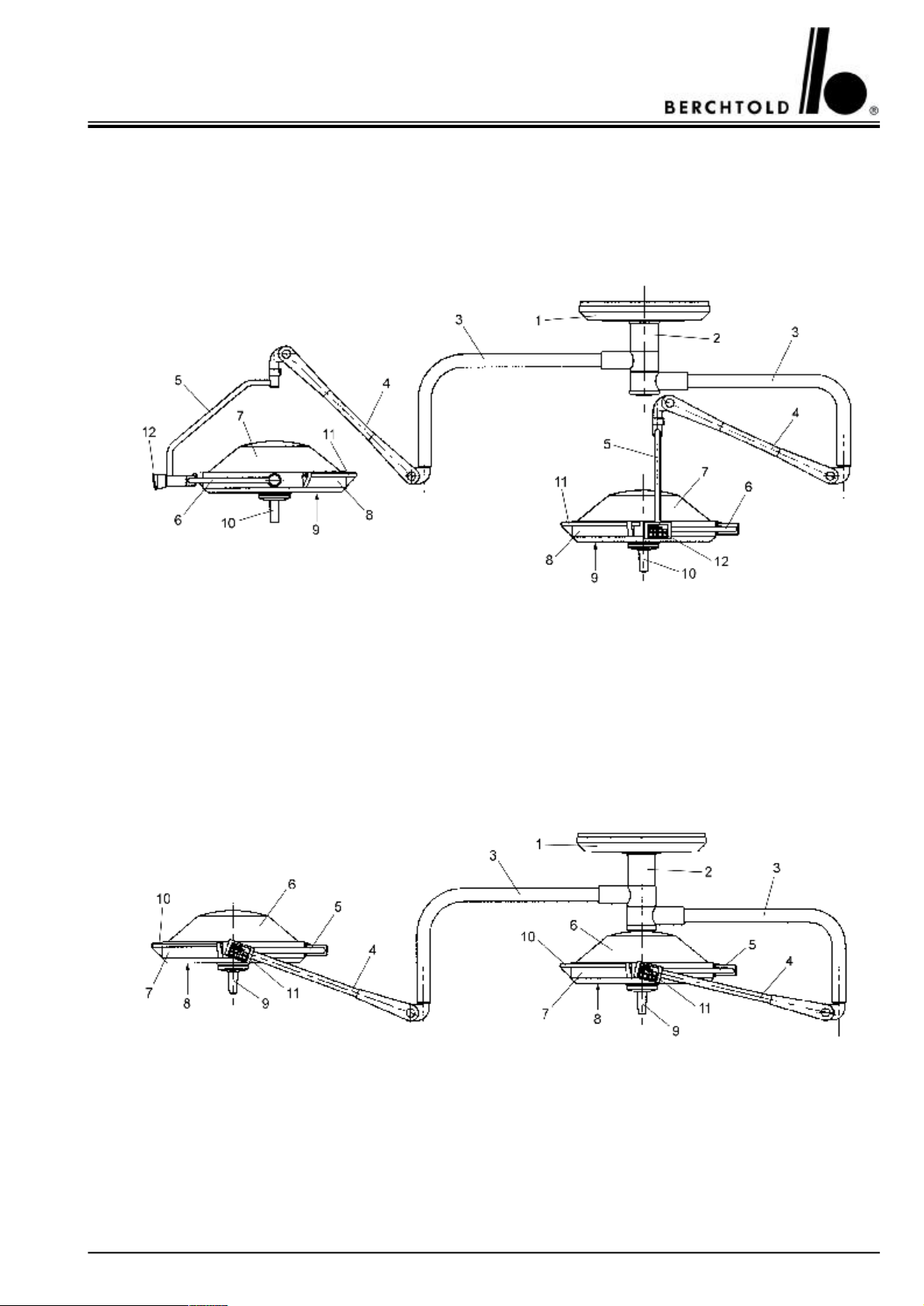
3.1.1 CHROMOPHARE® D 650plus/650plus, D 650/650 (classic cardanic)
1Ceiling cover7Lamp housing hood
2Flange tube dia. 125 mm8Lamp frame
3Horizontal swivel arm9Light emission lens
4Vertical spring arm10Sterilizable hand grip sleeves
5Vertical gimbal joint11Rail (encircling hand grip)
6Horizontal gimbal joint12Control unit
3.1.2 CHROMOPHARE® D 650plus/650plus, D 650/650 (flat cardanic)
1Ceiling cover7Lamp frame
2Flange tube dia. 125 mm8Light emission lens
3Horizontal swivel arm9Sterilizable hand grip sleeves
4Vertical spring arm10Rail (encircling hand grip)
5Horizontal gimbal joint11Control unit
6Lamp housing hood
11
Page 12
CHROMOPHARE® D 650plus, D 530plus, D 500plus, D 650, D 530, D 500 Service Manual (E)
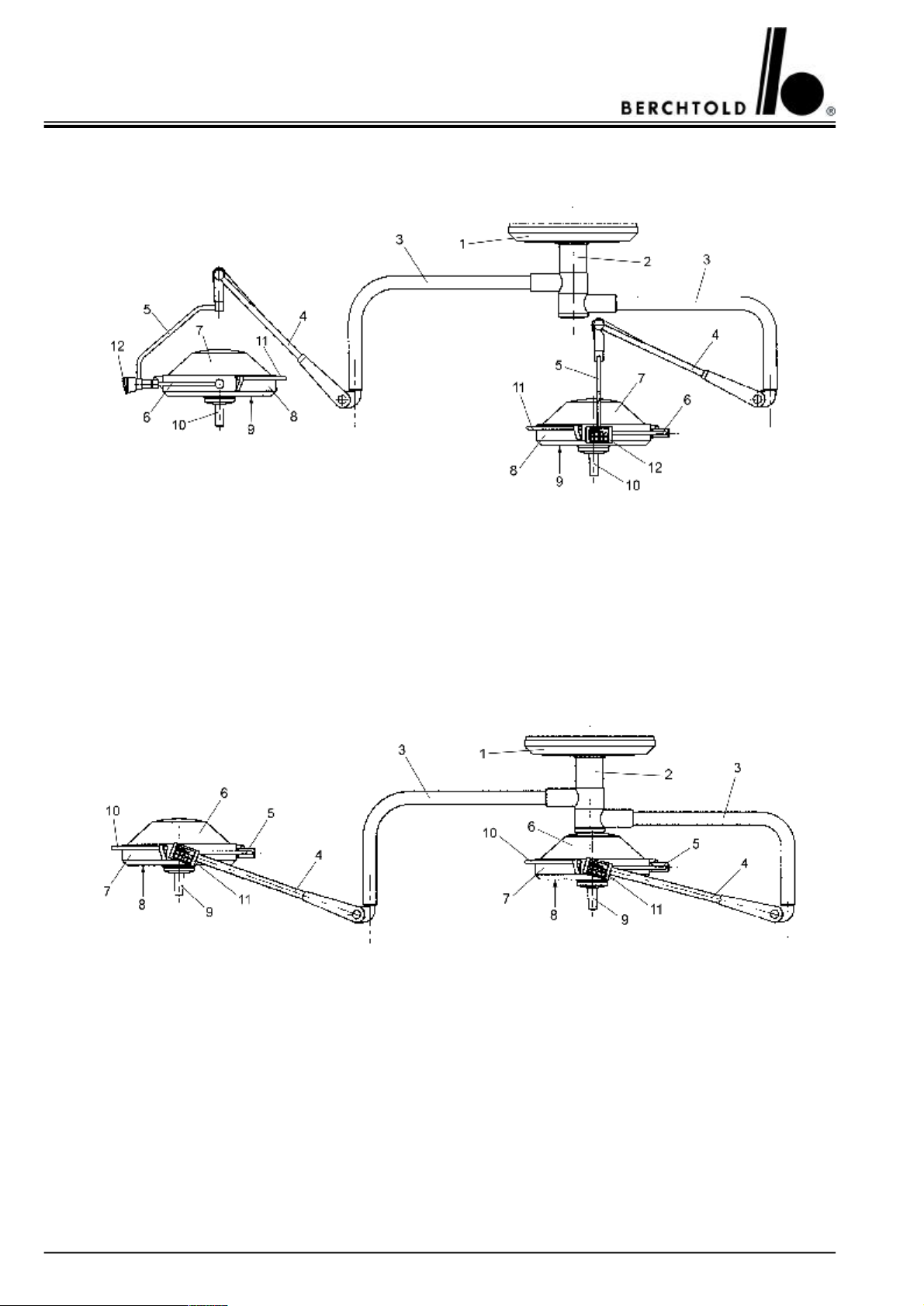
3.1.3 CHROMOPHARE® D 530plus/530plus, D 530/530 (classic cardanic)
1Ceiling cover7Lamp housing hood
2Flange tube dia. 125 mm8Lamp frame
3Horizontal swivel arm9Light emission lens
4Vertical spring arm10Sterilizable hand grip sleeves
5Vertical gimbal joint11Rail (encircling hand grip)
6Horizontal gimbal joint12Control unit
3.1.4 CHROMOPHARE® D 530plus/530plus, D 530/530 (flat cardanic)
1Ceiling cover7Lamp frame
2Flange tube dia. 125 mm8Light emission lens
3Horizontal swivel arm9Sterilizable hand grip sleeves
4Vertical spring arm10Rail (encircling hand grip)
5Horizontal gimbal joint11Control unit
6Lamp housing hood
12
Page 13
CHROMOPHARE® D 650plus, D 530plus, D 500plus, D 650, D 530, D 500 Service Manual (E)
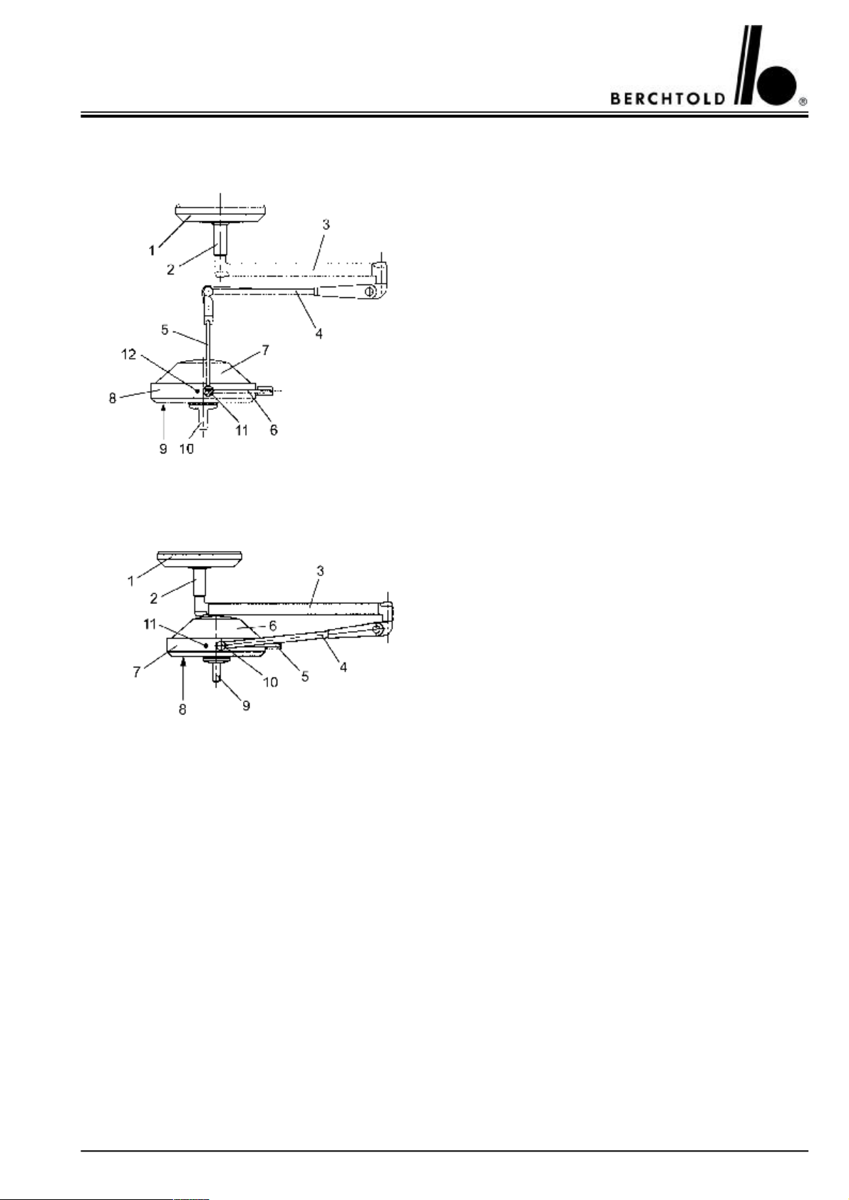
3.1.5 CHROMOPHARE® D 500plus, D 500 (classic cardanic)
1Ceiling cover
2Flange tube dia. 65 mm
3Horizontal swivel arm
4Vertical spring arm
5Vertical gimbal joint
6Horizontal gimbal joint
7Lamp housing hood
8Lamp frame
9Light emission lens
10Sterilizable hand grip sleeves
11On/Off switch
12Yellow indicator light reserve bulb
3.1.4 CHROMOPHARE® D 500plus, D 500 (flat cardanic)
1Ceiling cover
2Flange tube dia. 65 mm
3Horizontal swivel arm
4Vertical spring arm
5Horizontal gimbal joint
6Lamp housing hood
7Lamp frame
8Light emission lens
9Sterilizable hand grip sleeves
10On/Off switch
11Yellow indicator light reserve bulb
13
Page 14
CHROMOPHARE® D 650plus, D 530plus, D 500plus, D 650, D 530, D 500 Service Manual (E)
3.2 Notes on operation
3.2.1 Setting the control unit functions
3.2.1.1 CHROMOPHARE® D 650plus, D 650
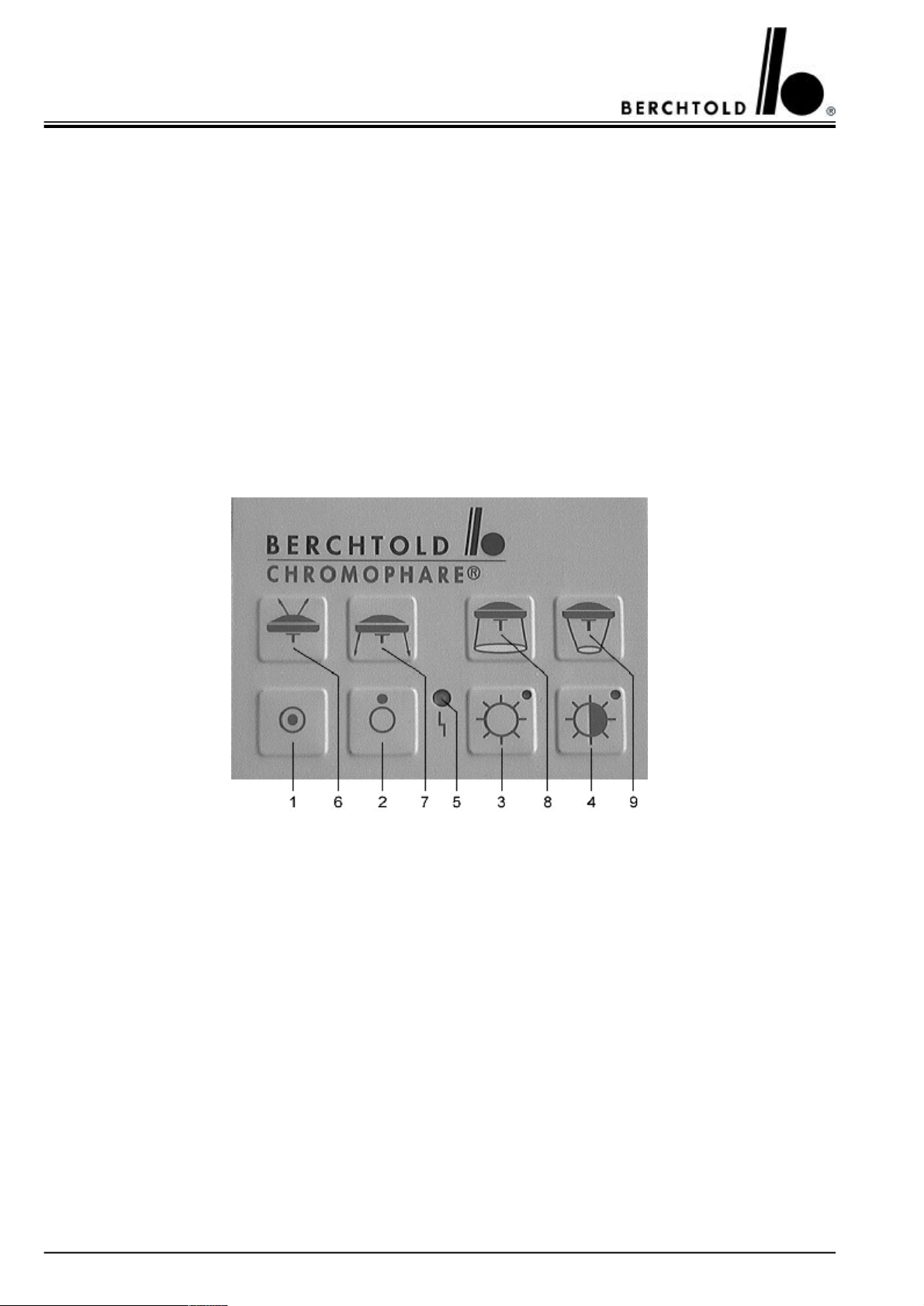
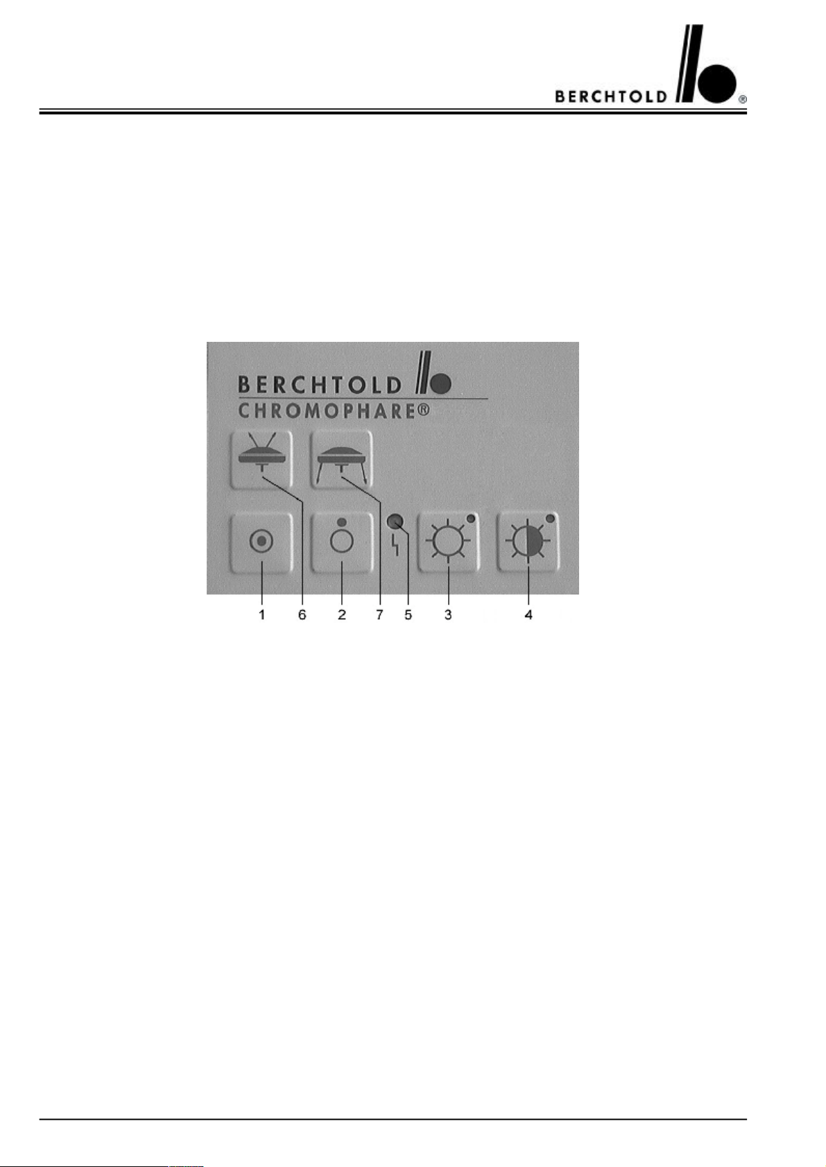
The following functions can be controlled by the control unit:
•On/off
•Intensity of illumination
Options:
•Electronic light field adjustment - only for LFN
•Switch over to EndoLite® surround light - switch to operating light - only with EndoLite® option
1
ONSwitch on the light
2
OFFSwitch off the light
3
BrightIncrease intensity
4
DarkDecrease intensity
5
FaultLED indicates that the control unit has a fault
Options:
6
EndoLite®Switch from surgical area light to surround light (option only)
7
OP lightSwitch from surround light to surgical area light
8
Field size largeEnlarge field size (only with LFN option)
9
Field size smallReduce field size (only with LFN option)
1The OP light is switched on by pressing Key 1 (ON)
2The OP light is switched off by pressing Key 2 (OFF)
3By pressing and holding down Key 3 (BRIGHT) the illuminance is continuously increased up to the maximum
value. Repeated short presses increase the illuminance in steps.
14
Page 15

CHROMOPHARE® D 650plus, D 530plus, D 500plus, D 650, D 530, D 500 Service Manual (E)
4By pressing and holding down Key 4 (DARK) the illuminance is continuously reduced down to the minimum
value. Repeated short presses decrease the illuminance in steps.
5If the indicator light shows red, there is a fault in the control unit electronics
6Only with the EndoLite® option. By pressing Key 6 EndoLite® the surgical area illumination is switched off and
the surround lighting is switched on
7Only with the EndoLite® option. By pressing Key 7 (OP light) the EndoLite® surround lighting is switched off
and the surgical area lighting is switched on again.
8Only with the LFN model. By pressing and holding down Key 8 (field size large) the light field is continuously
enlarged up to the maximum value. Repeated short presses enlarge the light field in steps.
9Only with the LFN model. By pressing and holding down Key 9 (field size small) the light field is continuously
reduced down to the minimum value. Repeated short presses reduce the light field in steps.
Booster activation
1.Press key 4 (Bright) until LED flashes up in the key (max. brightness).
2.The light booster will be activated by pressing simultaneously the key 1 (ON) and 3 (Bright). Luminous power
rises from 110 kLux to 130 kLux.
Note!
The light booster is deactivated by switching off the light with key 2 (OFF).
15
Page 16
CHROMOPHARE® D 650plus, D 530plus, D 500plus, D 650, D 530, D 500 Service Manual (E)
3.2.1.2 CHROMOPHARE® D 530plus, D 530
The following functions can be controlled by the control unit:
•On/off
•Intensity of illumination
Options:
•Switch over to EndoLite® surround light - switch to operating light - only with EndoLite® option
1ONSwitch on the light
2
OFFSwitch off the light
3
BrightIncrease intensity
4
DarkDecrease intensity
5
FaultLED indicates that the control unit has a fault
Options:
6
EndoLite®Switch from surgical area light to surround light (option only)
7
OP lightSwitch from surround light to surgical area light
1The OP light is switched on by pressing Key 1 (ON)
2The OP light is switched off by pressing Key 2 (OFF)
3By pressing and holding down Key 3 (BRIGHT) the illuminance is continuously increased up to the maximum
value. Repeated short presses increase the illuminance in steps.
4By pressing and holding down Key 4 (DARK) the illuminance is continuously reduced down to the minimum
value. Repeated short presses decrease the illuminance in steps.
5If the indicator light shows red, there is a fault in the control unit electronics
6Only with the EndoLite® option. By pressing Key 6 EndoLite® the surgical area illumination is switched off
and the surround lighting is switched on
16
Page 17

CHROMOPHARE® D 650plus, D 530plus, D 500plus, D 650, D 530, D 500 Service Manual (E)
7Only with the EndoLite® option. By pressing Key 7 (OP light) the EndoLite® surround lighting is switched off
and the surgical area lighting is switched on again.
3.2.1.3 CHROMOPHARE® D 500plus, D 500
The following functions can be controlled by the control unit:
• On/Off
1 ONSwitch on the light
1 OFFSwitch off the light
1The OP light is switched on by pressing Key 1 (ON)
2The OP light is switched off by pressing Key 2 (OFF)
17
Page 18
CHROMOPHARE® D 650plus, D 530plus, D 500plus, D 650, D 530, D 500 Service Manual (E)
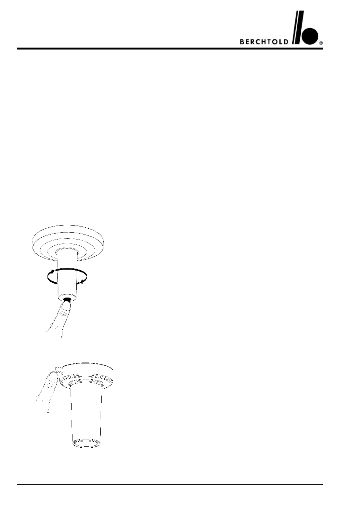
3.2.2 Adjusting the field size with the centre hand grip
By turning the sterilizable centre hand grip the size of the light field is changed. By turning the hand grip in the
clockwise direction the light field is enlarged, by turning anti-clockwise the light field is reduced. The surgeon must
perform the optimum field setting himself in accordance with the size of the operation opening. There is an optimum contrast when the field size is set approx. 2 - 3 cm larger than the operation opening, so that the edge of the
sterile covering is also illuminated. Thus the adaptation of the surgeon’s eyes in the whole field of vision is improved.
3.2.3Adjusting the field size - light field plotting model LFN (option only D 650plus, D 650)
The CHROMOPHARE® D 650plus and D 650 with light field plotting allows the field size to be adjusted by an
electric motor.
By pressing and holding down Key 8 (see control unit page 14) the light field is continuously enlarged up to the
maximum value. By repeated short presses the light field is enlarged in steps.
By pressing and holding down Key 9 (see control unit page 14) the light field is continuously reduced down to the
minimum value. By repeated short presses the light field is reduced in steps.
3.2.4 Changing the sterizable hand grip
By pressing the release button the hand grip sleeve is released and can be removed from the sleeve mounting. The new sterilized replacement sleeve is
pushed onto the sleeve mounting until it touches the stop and is then turned in
a clockwise direction until the sleeve locks into place.
3.2.5Changing the sterizable hand grip light field plotting model LFN (option only D 650plus, D 650)
The sterilizable hand grip sleeve is released by pressure on the bolt on the
upper collar of the sleeve. It can then be removed from the sleeve
mounting.
The new sterilized replacement sleeve is pushed onto the sleeve mounting
until it touches the stop and is then turned in a clockwise direction until
the sleeve is heard locking into place.
18
Page 19
CHROMOPHARE® D 650plus, D 530plus, D 500plus, D 650, D 530, D 500 Service Manual (E)
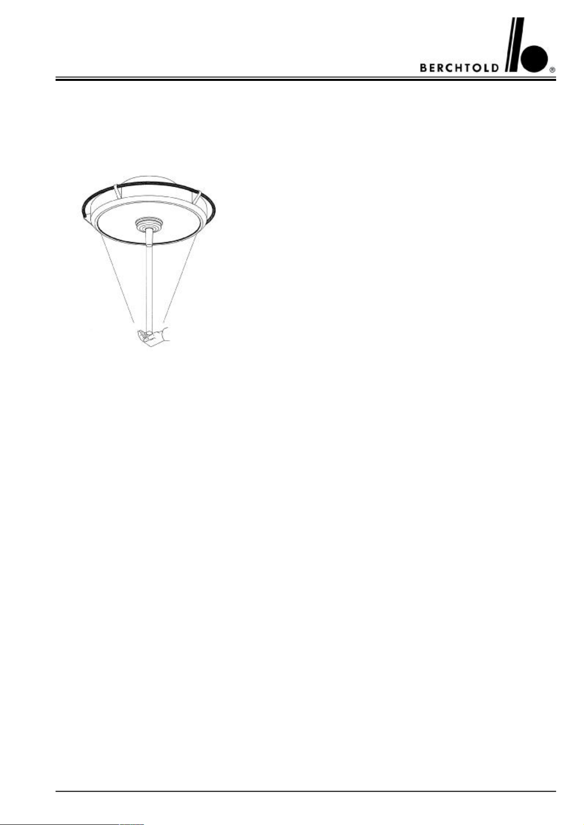
3.2.6 Light field plotting model LFN (option only D 650plus, D 650)
The CHROMOPHARE® D 650plus und D 650 can be ordered with an LFN light field plotter as an option. The
light field plotter is an electronic control system, which moves the lamps by electric motor. An infrared beam
which is reflected by a reflector disk controls the light field plotter.
The operator can direct the light field to the position which guarantees
optimum illumination of the surgical area, by means of a reflector disk, the
so-called „Light Pilot“.
The „Light Pilot“ should be held in the centre of the light field as far as
possible and then slowly moved to the desired position. If movement is
too quick, the light field will not be able to follow the „Light Pilot“.
This rule is: Wherever the light field is , the „Light Pilot“ will be hit by the
infrared beam and can reflect the beam back.
3.3 Accessories for CHROMOPHARE® generation D
3.3.1 Sterilizable hand grip sleeves
• Standard replacement sleevesOrder no. CZ 499-06
• Replacement sleeves for LFN (only D 650plus, D 650)Order no. CZ 498-04
• Replacement sleeves for light system with ChromoVision® AFIIOrder no. CZ 498-06
Note!
Each CHROMOPHARE® D 650plus light system has sterilizable handles.
For directions about cleaning, disinfection and sterilization, see page 10.
3.3.2 Halogen bulbs (reserve halogen bulbs)
3.3.2.1 CHROMOPHARE® D 650plus, D 530plus, D 500plus
• Halogen bulb 22,8 V/ 150 WOrder no. CZ 908-22
3.3.2.2 CHROMOPHARE® D 650
• for light with color temperature 4500K 22,8 V/ 250 WOrder no. CZ 907-22
• for light with color temperature 3600K 22,8 V/ 150 WOrder no. CZ 908-22
3.3.2.3 CHROMOPHARE® D 530, D 500
• for light with color temperature 4500K 22,8 V/ 150 WOrder no. CZ 908-22
• for light with color temperature 3600K 22,8 V/ 110 WOrder no. CZ 905-22
19
Page 20

CHROMOPHARE® D 650plus, D 530plus, D 500plus, D 650, D 530, D 500 Service Manual (E)
3.4 Systemvarianten
The CHROMOPHARE® generation D is available in the following system variants:
1. CHROMOPHARE® D 650plus as a single light
2. CHROMOPHARE® D 650plus as a double and a triple light
3. CHROMOPHARE® D 650plus as a combination light with D 530plus
4. CHROMOPHARE® D 650plus as a combination light with D 500plus
5. CHROMOPHARE® D 530plus as a single light
6. CHROMOPHARE® D 530plus as a double and a triple light
7. CHROMOPHARE® D 500plus as a single light
8. CHROMOPHARE® D 500plus as a double light
3.5 Options
The CHROMOPHARE® generation D can be supplemented or upgraded with the following options:
•Light carrier arm for up to 15 kg load with AC and PA connections for an auxiliary device for example. (Only
possible if the light has been prepared for an additional arm in advance)
•Supply carrier arm for up to 25 kg load with AC and PA connections, prepared for gas supply. This option must
be ordered with the lighting system (not upgradeable).
•Wall control unit for installation into a wall indicator panel. Functions such as switching on/off and brightness
of the OP light can then be controlled from the wall. (not upgradeable).
•EndoLite® - an environment illumination f0r MIS-surgeries, a 20 Watts halogen bulb integrated in the light
head, activated when the main light is switched off.
3.6 Instructions for changing lamps
The halogen bulb has an average life of 1000 hours. In the event of failure of the main lamp, switch over to a reserve lamp occurs automatically and the reserve lamp swivels automatically into the former position of the main
lamp.
A red indicator lights up on the lamp housing when the lamp safety system has switched over to the reserve lamp.
The defective main lamp should then be exchanged as quickly as possible.
The bulbs must be replaced in the following manner:
The symbol with the meaning ‘Danger - Risk of Burning’ is placed on the lamp support.
20
Page 21
CHROMOPHARE® D 650plus, D 530plus, D 500plus, D 650, D 530, D 500 Service Manual (E)
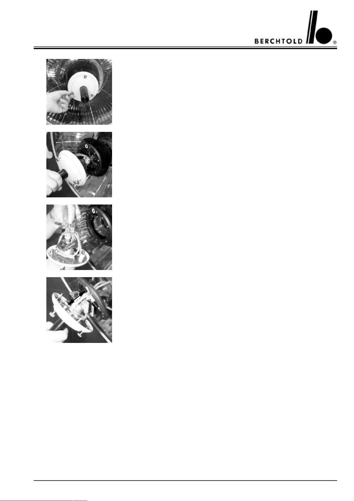
Switch off the lighting system and let it cool down (risk of burning). During replacement of the lamps the patient must not be touched as it is possible to come into contact with parts under tension.
Release and remove sterilizable handle.
Unscrew the knurled screw on the underside of the light by turning anti-clockwise.
Pull out the whole light system at the hand grip.
Remove a faulty halogen lamp. We advise users to insert the reserve lamp into the
main light lamp holder , marked with <R>, and to insert the new halogen lamp in the
reserve lamp holder so that the reserve lamp does not become too worn.
Fit a new halogen bulb into the bulb holder, - for the booking reference number see
paragraph 3.3.2 halogen bulb on page 19 - ( do not touch the quartz cone of the halogen bulb with your bare fingers, use a cloth or soft paper). During a lamp change
check the bulb holder for scorch marks. If scorch marks are present, inform our
service department.
Fit the light system back into the holder (picture 4) an screw up the knurled crews in a
clockwise direction.
Switch the lighting system on and check that the lamp is on and the red indicator light
is off.
Note!
Only use original BERCHTOLD halogen bulbs. If other bulbs are used, all guarantees regarding performance and operation will lapse.
21
Page 22
CHROMOPHARE® D 650plus, D 530plus, D 500plus, D 650, D 530, D 500 Service Manual (E)
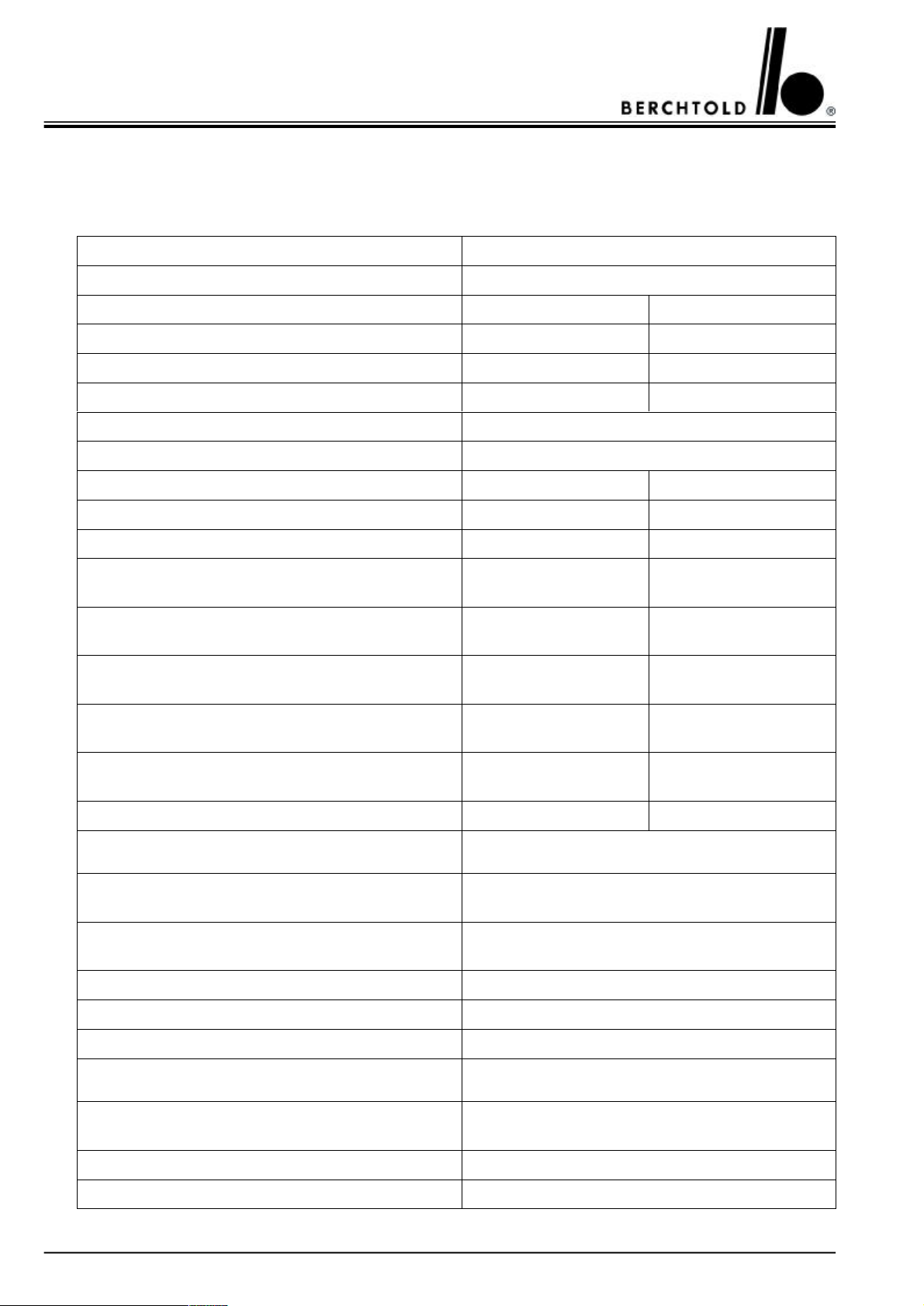
4.TECHNICAL DATA
4.1 CHROMOPHARE® D 650plus
Light technical dataD 650plus
Reflector systemPolygon reflector
Colour temperature4500 K3600 K
Intensity Ec at 1 m [klx]130150
Intensity control [klx]70 - 13070 - 150
Total radiant power at max intensity485 W/m
Total radiant power/intensity Ec [mW/m2lux]3,7
2
555 W/m
2
Colour rendering index R
a
94
Light field diameter15 – 28 cm15 – 28 cm
d
Light field dia. at 10% of max intensity15 cm15 cm
10
d
Light field dia. at 50% of max intensity8 cm8 cm
50
Remaining illuminance when beam is obstructed by
one mask47 %47 %
Remaining illuminance when beam is obstructed by
two mask45 %45 %
Remaining illuminance inside at the bottom of a
standardised tube.100 %100 %
Remaining illuminance inside at the bottom of a
standardised tube. Beam obstructed by one mask47 %47 %
Remaining illuminance inside at the bottom of a
standardised tube. Beam obstructed by two mask45 %45 %
Depth of illumination L1 + L2120 cm120 cm
Electrical data
Primary voltage of transformer100 / 120 / 127 V A.C.
220 / 230 / 240 V A.C.
Power consumption240 VA
or 170 AV at 24 V D.C.
Rated capacity of transformer / frequency240 VA / 50/60 Hz
Safety Category1
Protection provided by enclosureIP 53
General data
Halogen bulb
Order no.
22,8 V / 150 W
CZ 908-22
Life time of halogen bulb1000 h
Automatic switch over to reserve bulbyes
22
Page 23
CHROMOPHARE® D 650plus, D 530plus, D 500plus, D 650, D 530, D 500 Service Manual (E)
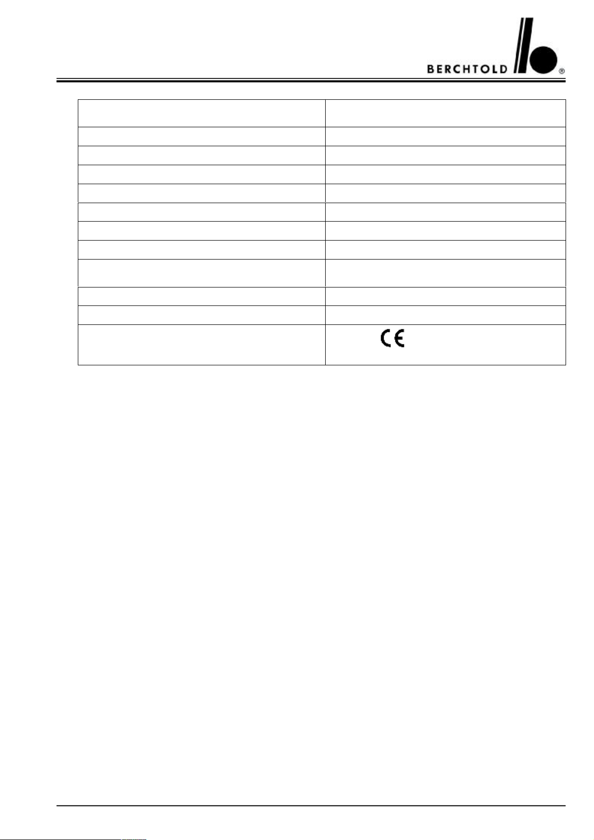
DimensionsD 650plus
Diameter of light body65 cm
Diameter of Polygon Reflectors58,5 cm
Light emission surface (glass surface)2370 cm
2
Max. swivel radius237 cm
Lowest position of light body128 cm
Highest position of light body226 cm
Clearance (single light)200 cm at 265 cm finished ceiling
Weight / Torque
Weight with transformer50 kg
Max. torque342 Nm
Certificate conform with 93/42 EEC
UL listed
23
Page 24
CHROMOPHARE® D 650plus, D 530plus, D 500plus, D 650, D 530, D 500 Service Manual (E)
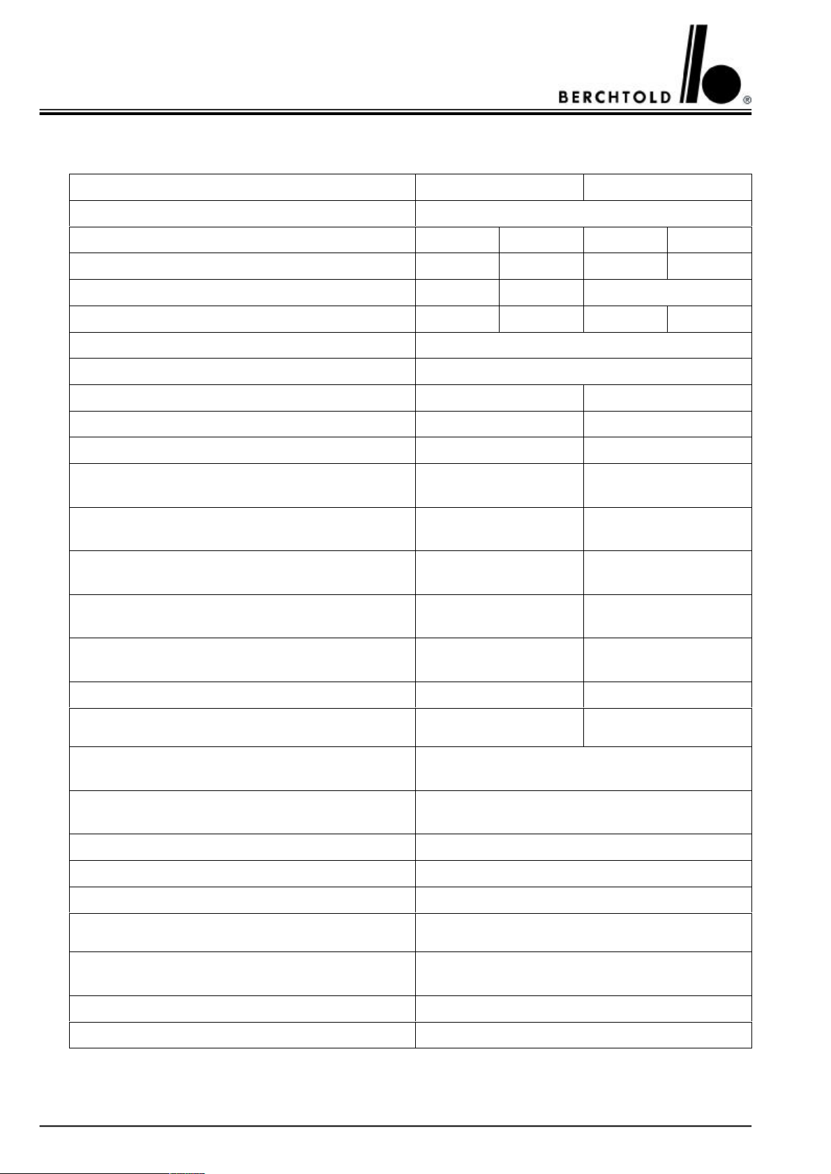
4.2 CHROMOPHARE® D 530plus, D 500plus
Light technical dataD 530plusD 500plus
Reflector systemPolygon reflector
Colour temperature4500plus K3600 K4500plus K3600 K
Intensity Ec at 1 m [klx]11014090115
Intensity control [klx]55 - 11070 - 140no
Total radiant power at max intensity410 W/m2518 W/m2336 W/m2426 W/m
Total radiant power/intensity Ec [mW/m2lux]3,7
2
Colour rendering index R
a
94
Light field diameter15 – 25 cm17 cm
d
Light field dia. at 10% of max intensity15 cm17 cm
10
d
Light field dia. at 50% of max intensity8 cm8,5 cm
50
Remaining illuminance when beam is obstructed by
one mask27 %31 %
Remaining illuminance when beam is obstructed by
two mask43 %42 %
Remaining illuminance inside at the bottom of a
standardised tube.100 %100 %
Remaining illuminance inside at the bottom of a
standardised tube. Beam obstructed by one mask27 %31 %
Remaining illuminance inside at the bottom of a
standardised tube. Beam obstructed by two mask43 %42 %
Depth of illumination L1 + L2125 cm125 cm
Electrical data
Primary voltage of transformer100 / 120 / 127 V A.C.
220 / 230 / 240 V A.C.
Power consumption240 VA
or 170 VA at 24 V D.C.
Rated capacity of transformer / frequency240 VA 50/60 Hz
Safety Category1
Protection provided by enclosureIP 53
General data
Halogen bulb at colour temperature 4500plus K
Order no.
22,8 V / 150 W
CZ 908-22
Life time of halogen bulb1000 h
Automatic switch over to reserve bulbyes
24
Page 25
CHROMOPHARE® D 650plus, D 530plus, D 500plus, D 650, D 530, D 500 Service Manual (E)
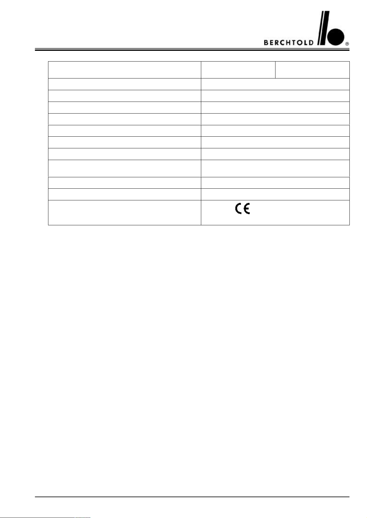
DimensionsD 530plusD 500plus
Diameter of light body52 cm
Diameter of Polygon Reflectors45,5 cm
Light emission surface (glass surface)1374 cm
2
Max. swivel radius231 cm
Lowest position of light body130 cm
Highest position of light body219 cm
Clearance (single light)200 cm at 245 cm finished ceiling
Weight / Torque
Weight with. transformer35 kg
Max. torque269 Nm
Certificate conform with 93/42 EEC
UL listed
25
Page 26
CHROMOPHARE® D 650plus, D 530plus, D 500plus, D 650, D 530, D 500 Service Manual (E)
4.3 CHROMOPHARE® D 650
Light technical dataD 650
Reflector systemPolygon reflector
Colour temperature4500 K3600 K
Intensity Ec at 1 m [klx]140140
Intensity control [klx]70 - 14070 - 140
Total radiant power at max intensity520 W/m
2
Total radiant power/intensity Ec [mW/m2lux]3,7
Colour rendering index R
a
94
Light field diameter20 – 32 cm17 – 30 cm
d
Light field dia. at 10% of max intensity20 cm17 cm
10
d
Light field dia. at 50% of max intensity10 cm9 cm
50
Remaining illuminance when beam is obstructed by
one mask59 %50 %
Remaining illuminance when beam is obstructed by
two mask48 %46 %
Remaining illuminance inside at the bottom of a
standardised tube.100 %100 %
Remaining illuminance inside at the bottom of a
standardised tube. Beam obstructed by one mask59 %50 %
Remaining illuminance inside at the bottom of a
standardised tube. Beam obstructed by two mask48 %46 %
Depth of illumination L1 + L2120 cm120 cm
Electrical data
Primary voltage of transformer100 / 120 / 127 V A.C.
220 / 230 / 240 V A.C.
Power consumption370 VA
or 270 VA at 24 V D.C.
or 170 AV at 24 V D.C.
Rated capacity of transformer / frequency400 VA / 50/60 Hz250 VA / 50/60 Hz
Safety Category1
Protection provided by enclosureIP 53
26
240 VA
Page 27
CHROMOPHARE® D 650plus, D 530plus, D 500plus, D 650, D 530, D 500 Service Manual (E)
General dataD 650
Halogen bulb
Order no.
22,8 V / 250 W
CZ 907-22
22,8 V / 150 W
CZ 908-22
Life time of halogen bulb1000 h
Automatic switch over to reserve bulbyes
Dimensions
Diameter of light body65 cm
Diameter of Polygon Reflectors58,5 cm
Light emission surface (glass surface)2370 cm
2
Max. swivel radius237 cm
Lowest position of light body128 cm
Highest position of light body226 cm
Clearance (single light)200 cm at 265 cm finished ceiling
Weight / Torque
Weight with transformer50 kg
Max. torque342 Nm
Certificate conform with 93/42 EEC
UL listed
27
Page 28
CHROMOPHARE® D 650plus, D 530plus, D 500plus, D 650, D 530, D 500 Service Manual (E)
4.4 CHROMOPHARE® D 530, D 500
Light technical dataD 530D 500
Reflector systemPolygon reflector
Colour temperature4500 K3600 K4500 K3600 K
Intensity Ec at 1 m [klx]11090
Intensity control [klx]55 - 110no
Total radiant power at max intensity410 W/m
2
336 W/m
2
Total radiant power/intensity Ec [mW/m2lux]3,7
Colour rendering index R
a
94
Light field diameter17 – 28 cm17 cm
d
Light field dia. at 10% of max intensity17 cm17 cm
10
d
Light field dia. at 50% of max intensity8,5 cm10 cm
50
Remaining illuminance when beam is obstructed by
one mask27 %31 %
Remaining illuminance when beam is obstructed by
two mask43 %42 %
Remaining illuminance inside at the bottom of a
standardised tube.100 %100 %
Remaining illuminance inside at the bottom of a
standardised tube. Beam obstructed by one mask27 %31 %
Remaining illuminance inside at the bottom of a
standardised tube. Beam obstructed by two mask43 %42 %
Depth of illumination L1 + L2130 cm130 cm
Electrical data
Primary voltage of transformer100 / 120 / 127 V A.C.
220 / 230 / 240 V A.C.
Power consumption240 VA
or 170 VA
at 24 V
D.C.
200 VA
or 140 VA
at 24 V
D.C.
or 170 VA
Rated capacity of transformer / frequency240 VA / 50/60 Hz140 VA / 50/60 Hz
Safety Category1
Protection provided by enclosureIP 53
28
240 VA
at 24 V
D.C.
200 VA
or 140 VA
at 24 V
D.C.
Page 29
CHROMOPHARE® D 650plus, D 530plus, D 500plus, D 650, D 530, D 500 Service Manual (E)
General dataD 530D 500
Halogen bulb at colour temperature 4500 K
Order no.
Halogen bulb at colour temperature 3600 K
Order no.
22,8 V / 150 W
CZ 908-22
22,8 V / 110 W
CZ 905-22
Life time of halogen bulb1000 h
Automatic switch over to reserve bulbyes
Dimensions
Diameter of light body52 cm
Diameter of Polygon Reflectors45,5 cm
Light emission surface (glass surface)1374 cm
2
Max. swivel radius231 cm
Lowest position of light body130 cm
Highest position of light body219 cm
Clearance (single light)200 cm at 245 cm finished ceiling
Weight / Torque
Weight with. transformer35 kg
Max. torque269 Nm
Certificate conform with 93/42 EEC
UL listed
29
Page 30

CHROMOPHARE® D 650plus, D 530plus, D 500plus, D 650, D 530, D 500 Service Manual (E)
5.SERIAL NO. IDENTIFICATION
Type plate (A)
1Version number
2Variant
3Manufacturing year
4Serial number
6.SPARE PART LIST
6.1 CHROMOPHARE® D 650plus, D 650
DescriptionPart no.Picture on page
Filtering board6560640
Reverse polarity protection6560141
Light intensity power circuit board6560442
Hexagon socket countersunk head screw28443
Locking pin6417443
Sliding contact6418643
Brake screw3882143
Cross recessed oval-head screw27743
Distance sleeve6478343
Cover6417143
Contact block for sliding contacts3969343
Cross recessed oval-head screw23543
30
Page 31

CHROMOPHARE® D 650plus, D 530plus, D 500plus, D 650, D 530, D 500 Service Manual (E)
DescriptionPart no.Picture on page
Male sliding contact6524143
Female sliding contact2000243
Brake screw6410343
Cross recessed raised cheese head screw4539643
Mortise screw6412643
Brake screw4280544
Positioning screw4300944
Brake screw4280344
Ejot screw6466944
Hood6410144
Sealing rubber6467744
Screw6423544
Indication lamp yellow, with cable and connector6563744
Cover5113544
Rail holder6225244
Rail6414544
Test adapter5057445
Wiring harness6576945
Screw6807145
Brake screw M5x56807245
Countersunk head screw M3x126807345
Front part for touch control board6240245
Bumper, left6632046
Bumper, right6631946
Security lock – spring balanced arm2001046
Protection bush2001146
Washer2419746
Screw1165646
Guiding rod, with pressed socket for banana plug dia. 4 mm6477847
Filter glass assembly D 650plus6861847
Filter glass assembly D 6506415747
D.C. motor6799847 / 51
Control circuit board for centre positioning of main bulb6417648
Focusing mechanism for Standard and EndoLite®, without halogen
6416349
bulb
Guiding screw6415249
31
Page 32

CHROMOPHARE® D 650plus, D 530plus, D 500plus, D 650, D 530, D 500 Service Manual (E)
DescriptionPart no.Picture on page
O-ring6420349
Cover6241849 / 50
Connection board for Standard6416249
Holder for bulb with connecting cables6414649
Housing for touch control board for Standard6240750
Touch control board with foil for Standard6882350
Touch control board with foil for Standard with EndoLite®6882451
Reserve bulb switch over circuit board without EndoLite®6561051
Focusing mechanism for LFN and LFN with EndoLite®, without
halogen bulb
IR-module6564352 / 53
Pressure spring4517352
Cover6419452 / 53
Connection board for LFN6419752
Motor for LFN5486053
Gearwheel5484954
Ring for sliding clutch5480954
LFN control6560854
Housing for touch control board for LFN and LFN with EndoLite®6240154
Touch control board with foil for LFN6882554
Touch control board with foil for LFN with EndoLite®6882655
Spare bulb 12V/20W for EndoLite®CZ 960-1255
Reserve bulb switch over circuit board with EndoLite®6561155
6467352
32
Page 33

CHROMOPHARE® D 650plus, D 530plus, D 500plus, D 650, D 530, D 500 Service Manual (E)
6.2 CHROMOPHARE® D 530plus, D 500plus, D 530, D 500
DescriptionPart no.Picture on page
Filtering board6560640
Reverse polarity protection6560141
Light intensity power circuit board6560442
Hexagon socket countersunk head screw28443
Locking pin6417443
Sliding contact6418643
Brake screw3882143
Cross recessed raised cheese head screw27743
Distance sleeve6478343
Cover6417143
Contact block for sliding contacts3969343
Cross recessed countersunk head screw23543
Male sliding contact
6524143
Female sliding contact2000243
Brake screw6410343
Cross recessed raised cheese head screw4539643
Mortise screw6412643
Brake screw4280544
Positioning screw4300944
Brake screw4280344
Ejot screw6466944
Hood6633344
Sealing rubber6645244
Screw6423544
Indication lamp yellow, with cable and connector6563744
Cover5113544
Rail holder6225244
Rail6633044
Test adapter5057445
Wiring harness6576945
Screw6807145
Brake screw M5x56807245
Countersunk head screw M3x126807345
Front part for touch control board6240245
33
Page 34
CHROMOPHARE® D 650plus, D 530plus, D 500plus, D 650, D 530, D 500 Service Manual (E)
DescriptionPart no.Picture on page
Bumper, left
6632046
Bumper, right6631946
Housing for touch control board for D 530plus, D 5306240750
Touch control board for D 530plus, D 530 Standard6882350
Touch control board for D 530plus, D 530 Standard with
6882451
EndoLite®
Reserve bulb switch over circuit board without EndoLite®, D 530plus
6561051
D 530
Spare bulb 12V/20W for EndoLite®CZ 960-1255
Reserve bulb switch over circuit board with EndoLite®, D 530plus
6561155
D 530
Security lock – spring balanced arm2001056
Protection bush2001146
Washer2419756
Screw1165656
Guiding rod, with pressed socket for banana plug dia. 4 mm
6640657
for D 530plus, D 530
Guiding rod, with pressed socket for banana plug dia. 4 mm
6640557
for D 500plus, D 500
Filter glass assembly for D 530plus, D 5306640957
Filter glass assembly for D 500plus, D 5006645757
Focusing mechanism for Standard and EndoLite®, without halogen
6642158
bulb, for D 530plus, D 530
Holder for bulb6414658 / 59
Screw, lower stop6642258
Screw, upper stop6642358
Cover6241858 / 59
Knurled screw6414258 / 59
O-ring6420358 / 59
Connection board for Standard6416258 / 60
Focusing mechanism for Standard, without halogen bulb,
6641959
for D 500plus, D 500
Threaded rod3859359
Touch control board for D 500plus, D 5006641760
Housing for touch control board for D 500plus, D 5006641660
Countersunk-head screw M3x1610360
Circuit board On/Off for D 500plus, D 5006801560
34
Page 35
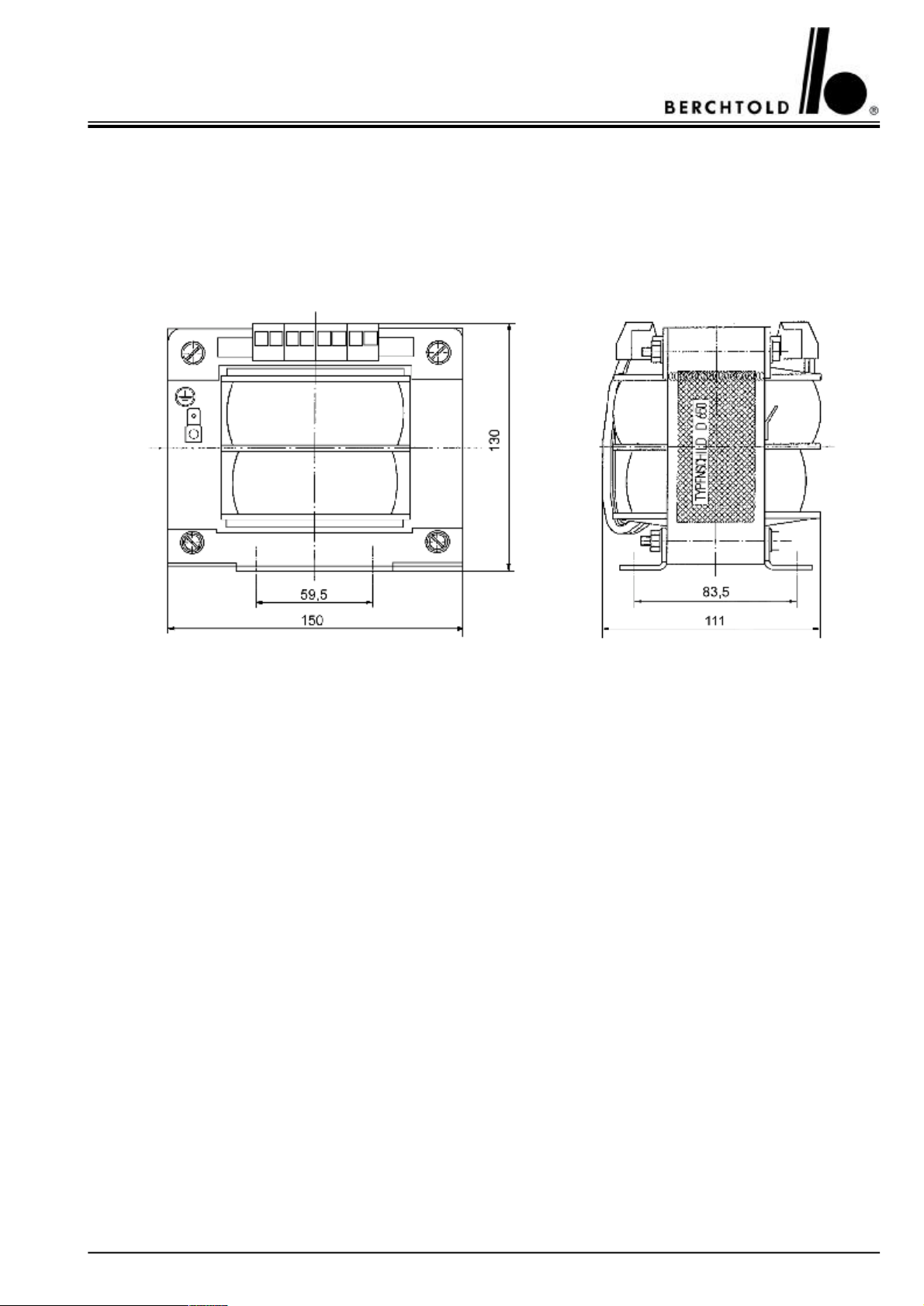
CHROMOPHARE® D 650plus, D 530plus, D 500plus, D 650, D 530, D 500 Service Manual (E)
7.TRANSFORMERS
7.1CHROMOPHARE® D 650
CHROMOPHARE® D 650plus, D 530plus, D 500plus
Mounting separate from the ceiling tube, distance of transformer to ceiling tube over 20 m
CB 502-40Transformer mounted on flange tube 220/230/240V / 400 VA
CB 505-40Transformer mounted separately 220/230/240V / 400 VA
CB 502-42Transformer mounted on flange tube 100/120/127 V / 400 VA
CB 505-42Transformer mounted separately 100/120/127 V / 400 VA
How to proceed the transformer adjustment (with topped filtering board):
1. Measuring of the terminal voltage on the ceiling terminal.
2. The terminal voltage of the emergency supply is similar to the reference value (D.C.). The reference value (D.C.)
is measured on the ceiling tube’s terminal connection situated behind the filtering board. The secondary tap on the
transformer should be chosen in that way that the above measured reference value (D.C.) is reached. This procedure is valid for separately mounted transformers with filtering board as well as on ceiling tube mounted transformers with filtering board.
The following taps can be chosen:
35
Page 36
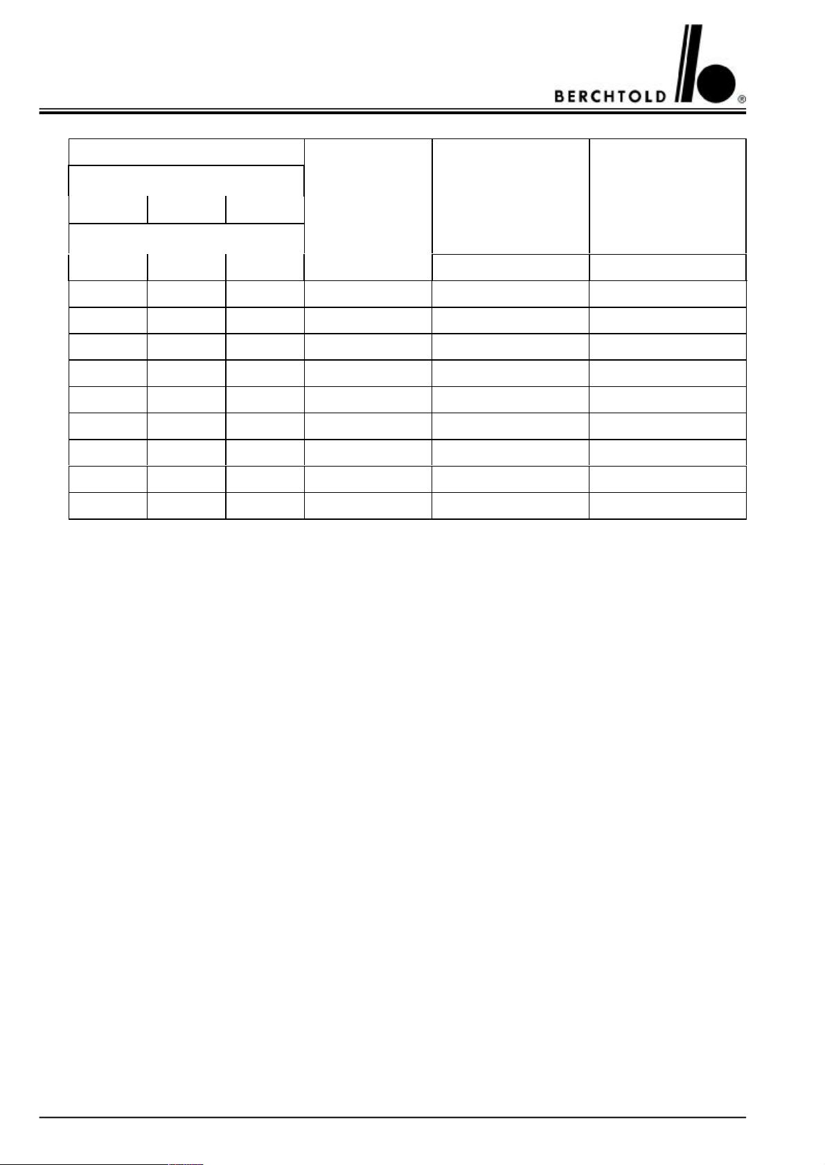
CHROMOPHARE® D 650plus, D 530plus, D 500plus, D 650, D 530, D 500 Service Manual (E)
Primary terminal main voltage
Trafo CB 502-42 or CB 505-42
100 V120 V127 V
Trafo CB 502-40 or CB 505-40
Secondary terminal
approx. A.C. voltage
at filtering board input
approx. D.C. voltage
at filtering board output
220 V230 V240 V
A.C. [V]D.C. [V]
1 / 51 / 61 / 78 / 921.524.0
2 / 52 / 62 / 78 / 922.024.6
3 / 53 / 63 / 78 / 922.525.1
1 / 51 / 61 / 78 / 1023.526.3
2 / 52 / 62 / 78 / 1024.026.8
3 / 53 / 63 / 78 / 1024.527.4
1 / 51 / 61 / 78 / 1125.028.0
2 / 52 / 62 / 78 / 1125.528.5
3 / 53 / 63 / 78 / 1126.029.0
Example 1:
Transformer and filtering board are mounted on the ceiling tube, emergency supply 25.0 V D.C. under load (reference value) on the terminal connection of the ceiling tube.
The transformer tap corresponds to 230 V supply voltage, 3 / 6 for the primary connection and 8 / 9 for the secondary tap.
Example 2:
Transformer and filtering board are mounted in the wall box, emergency supply 25.5 V D.C. under load (reference
value) on the terminal connection of the ceiling tube.
The wire’s voltage drop is 2 V.
The transformer tap corresponds to 230 V supply voltage, 3 / 6 for the primary connection and 8 / 10 for the
secondary tap.
Attention:
If the transformer and the filtering board are mounted separately, the wire’s voltage drop between the filtering
board’s output and the terminal connection of the ceiling tube has to be taken into account accordingly.
If the transformer is mounted on the ceiling tube, the smallest secondary tap (21.5 V) has to be chosen. After the
rectification on the filtering board, the above mentioned value corresponds to a D.C. voltage of ca. 24.0 V under
load.
36
Page 37
CHROMOPHARE® D 650plus, D 530plus, D 500plus, D 650, D 530, D 500 Service Manual (E)
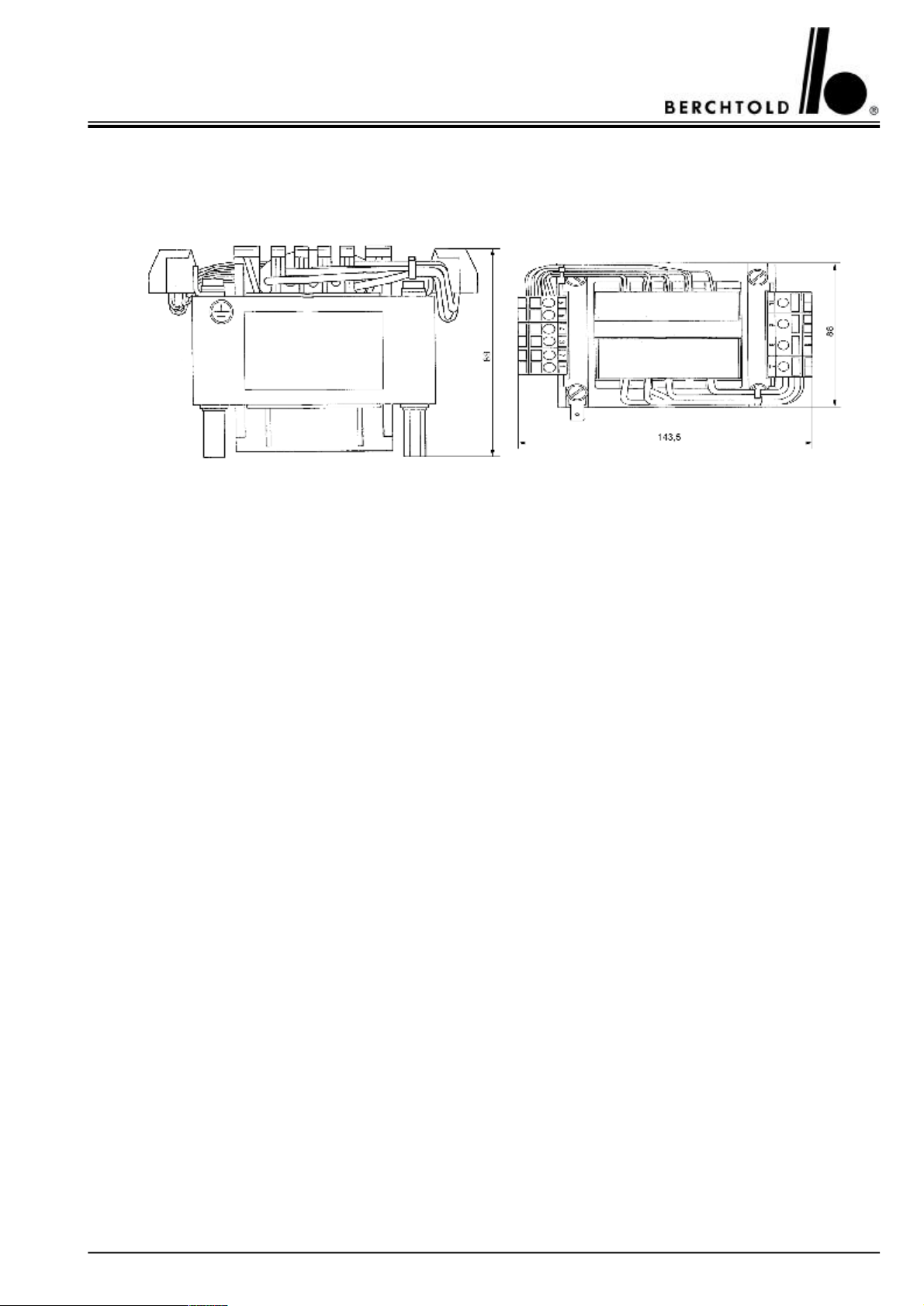
7.2CHROMOPHARE® D 650plus, D 530plus, D 500plus, D 530, D 500
Mounting on the ceiling tube and separate from the ceiling tube, distance of transformer to ceiling
tube 20 m
CB 502-32Transformer mounted on flange tube 220/230 V/240 VA
CB 505-32Transformer mounted separately 220/230 V/240 VA
CB 502-30Transformer mounted on flange tube 100/120/127 V/240 VA
CB 505-30Transformer mounted separately 100/120/127 V/240 VA
How to proceed the transformer adjustment (with topped filtering board):
1. Measuring of the terminal voltage on the ceiling terminal.
2. The terminal voltage of the emergency supply is similar to the reference value (D.C.). The reference value (D.C.)
is measured on the ceiling tube’s terminal connection situated behind the filtering board. The secondary tap on the
transformer should be chosen in that way that the above measured reference value (D.C.) is reached. This procedure is valid for separately mounted transformers with filtering board as well as on ceiling tube mounted transformers with filtering board.
The following taps can be chosen:
37
Page 38
CHROMOPHARE® D 650plus, D 530plus, D 500plus, D 650, D 530, D 500 Service Manual (E)
Primary terminal main voltage
Trafo CB 502-30 or CB 505-30
100 V120 V127 V
Trafo CB 502-32 or CB 505-32
Secondary terminal
approx. A.C. voltage
at filtering board input
approx. D.C. voltage
at filtering board output
220 V230 V240 V
A.C. [V]D.C. [V]
1 / 41 / 51 / 67 / 821.024.0
2 / 42 / 52 / 67 / 821.524.6
3 / 43 / 53 / 67 / 822.025.1
1 / 41 / 51 / 67 / 923.026.3
2 / 42 / 52 / 67 / 923.526.8
3 / 43 / 53 / 67 / 924.027.4
1 / 41 / 51 / 67 / 1024.528.0
2 / 42 / 52 / 67 / 102.,02.,5
3 / 43 / 53 / 67 / 1025.529.0
Example 1:
Transformer and filtering board are mounted on the ceiling tube, emergency supply 25.0 V D.C. under load (reference value) on the terminal connection of the ceiling tube.
The transformer tap corresponds to 230 V supply voltage, 3 / 5 for the primary connection and 7 / 8 for the secondary tap.
Example 2:
Transformer and filtering board are mounted in the wall box, emergency supply 25.5 V D.C. under load (reference
value) on the terminal connection of the ceiling tube.
The wire’s voltage drop is 2.0 V.
The transformer tap corresponds to 230 V supply voltage, 3 / 5 for the primary connection and 7 / 9 for the secondary tap.
Attention:
If the transformer and the filtering board are mounted separately, the wire’s voltage drop between the filtering
board’s output and the terminal connection of the ceiling tube has to be taken into account accordingly.
If the transformer is mounted on the ceiling tube, the smallest secondary tap (21.0 V) has to be chosen. After the
rectification on the filtering board, the above mentioned value corresponds to a D.C. voltage of ca. 24.0 V under
load.
38
Page 39
CHROMOPHARE® D 650plus, D 530plus, D 500plus, D 650, D 530, D 500 Service Manual (E)
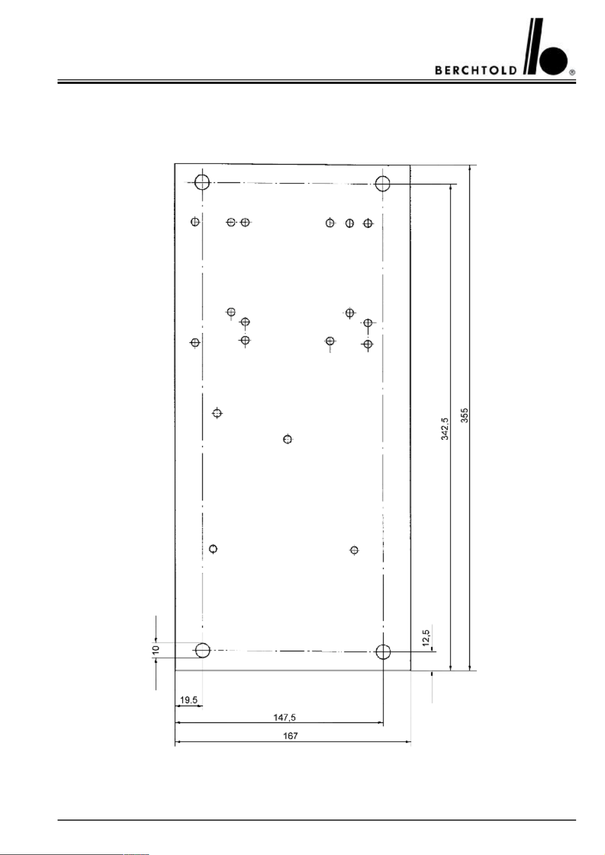
Drilling measurements mounting plate - supply unit
Planting depth min 200 mm
39
Page 40
CHROMOPHARE® D 650plus, D 530plus, D 500plus, D 650, D 530, D 500 Service Manual (E)
8.GRAPHIC SPARE PART DESCRIPTION
8.1 CHROMOPHARE® generation D complete
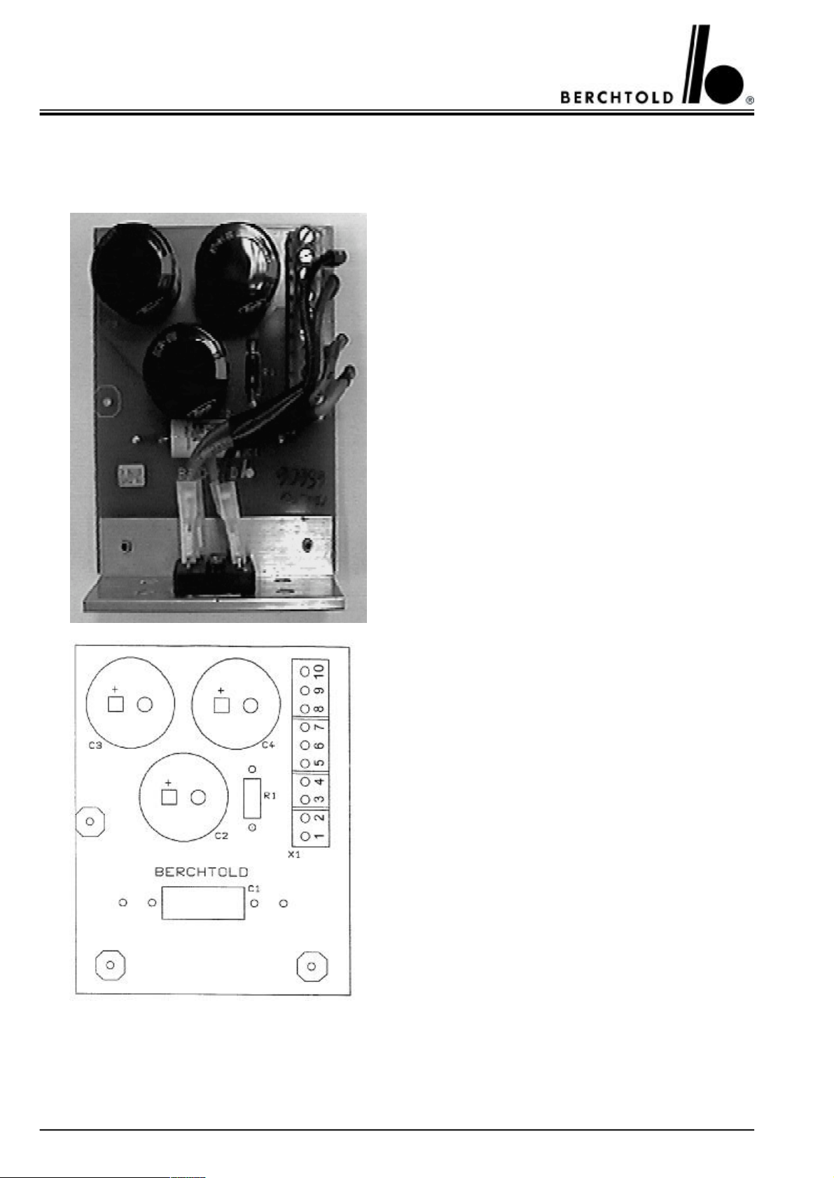
Filtering board, part no. 65606
Note!
Due to the EMV conditions, the filtering board has generally to be connected and installed as near as possible to
the transformer.
Please consider that the installed filtering board should be
able to eliminate heat through a large surface.
1AC K9, to emergency relays
2AC V1
3AC Transformer input
4AC V1
5AC Transformer input
6AC K9, to emergency relays
7+ V1
8+ out, to light 24 – 27 V D.C.
9– V1
10– out, to light 24 – 27 V D.C.
The wiring diagram please see page 72 - 95
40
Page 41
CHROMOPHARE® D 650plus, D 530plus, D 500plus, D 650, D 530, D 500 Service Manual (E)
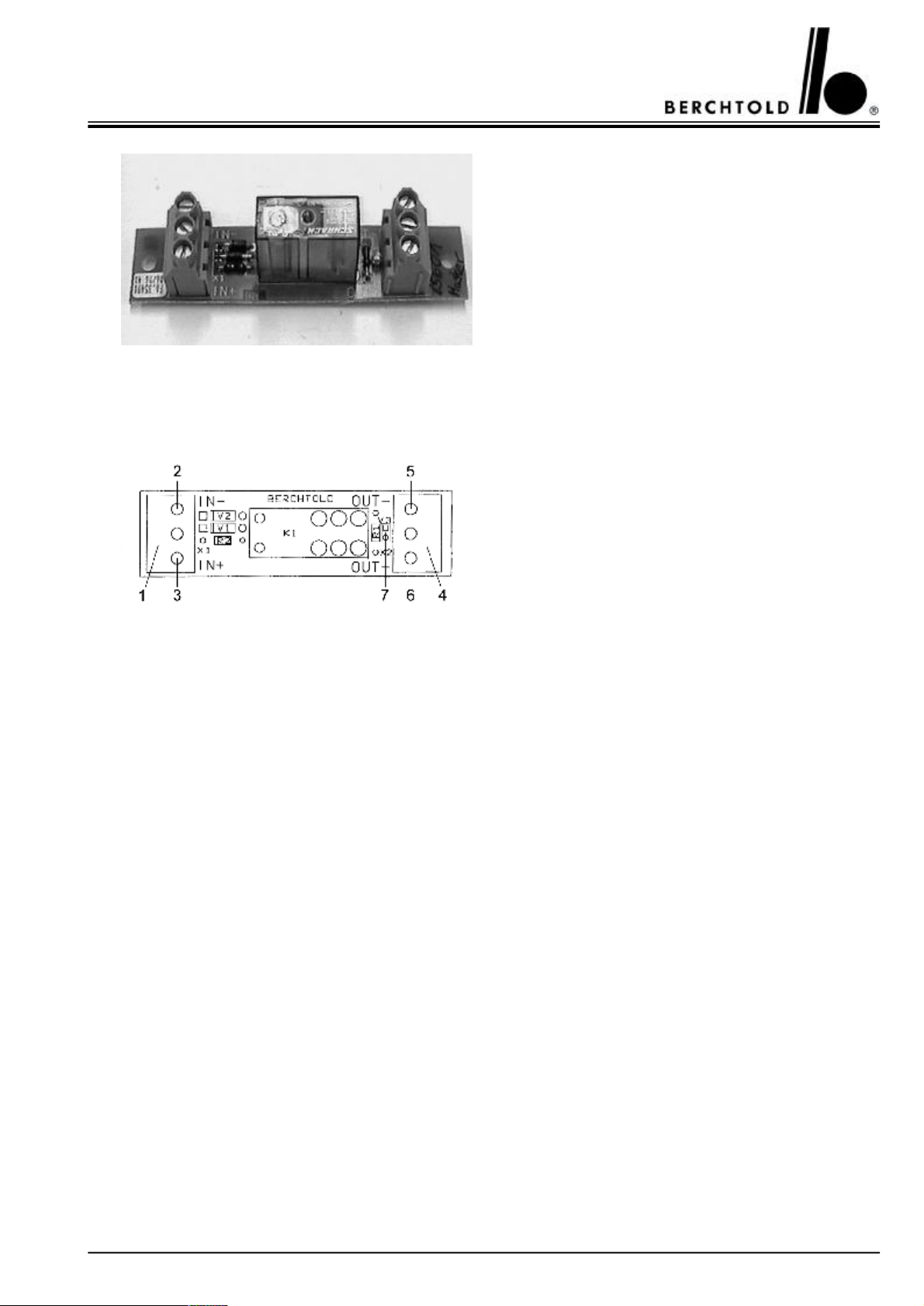
Reverse polarity protection, part no. 65601
In BERCHTOLD plant, a reverse polarity protection
module (part no. 65602) with fixation D 650plus, D 650
is installed on every ceiling tube. If welded central columns are used, the module is installed on the flange. A
green LED on the reverse polarity protection module
indicates the correct polarity, the presence of voltage as
well as the functioning of the reverse polarity protection
module.
All models with BERCHTOLD wall box have the reverse polarity protection module inside the wall box,
where it is preconnected to the electronics.
1input terminal: input voltage
24 – 27 V D.C.
2 - (negative) input (black cable)
3 + (positive) input (red cable)
4output terminal: output voltage
24 – 27 V D.C.
5 - negative) to light body (black cable)
6 + (positive) to light body (red cable)
7 indication LED V3
green indication = polarity o.k.
red indication = wrong polarity or A.C.
no indication = no voltage connected
41
Page 42
CHROMOPHARE® D 650plus, D 530plus, D 500plus, D 650, D 530, D 500 Service Manual (E)
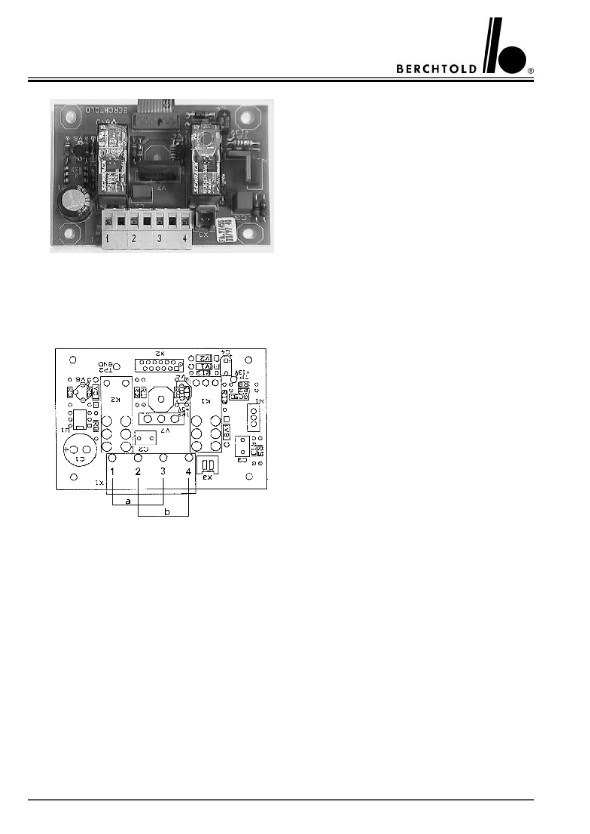
Light intensity power circuit board, part no. 65604
Attention!
No A.C. voltage must be fed into the electronics. A
direct supply of A.C. voltage always destroys the light
electronics.
If only A.C. voltage is available, the filtering board (part
no. 65606) has always to be preconnected to the light
electronics.
If only D.C. voltage is available, preconnecting of the
filtering board is not necessary.
If A.C. voltage (main supply) and D.C. voltage (supplementary supply) are available, the filtering board (part
no. 65606) has always to be preconnected to the light
electronics in the main supply circuitry.
ainput 23 – 26 V D.C.
boutput to light body max. 22,6 V A.C./D.C.
1black - (negative)
2black - (negative)
3red + (positive)
4red + (positive)
42
Page 43
CHROMOPHARE® D 650plus, D 530plus, D 500plus, D 650, D 530, D 500 Service Manual (E)
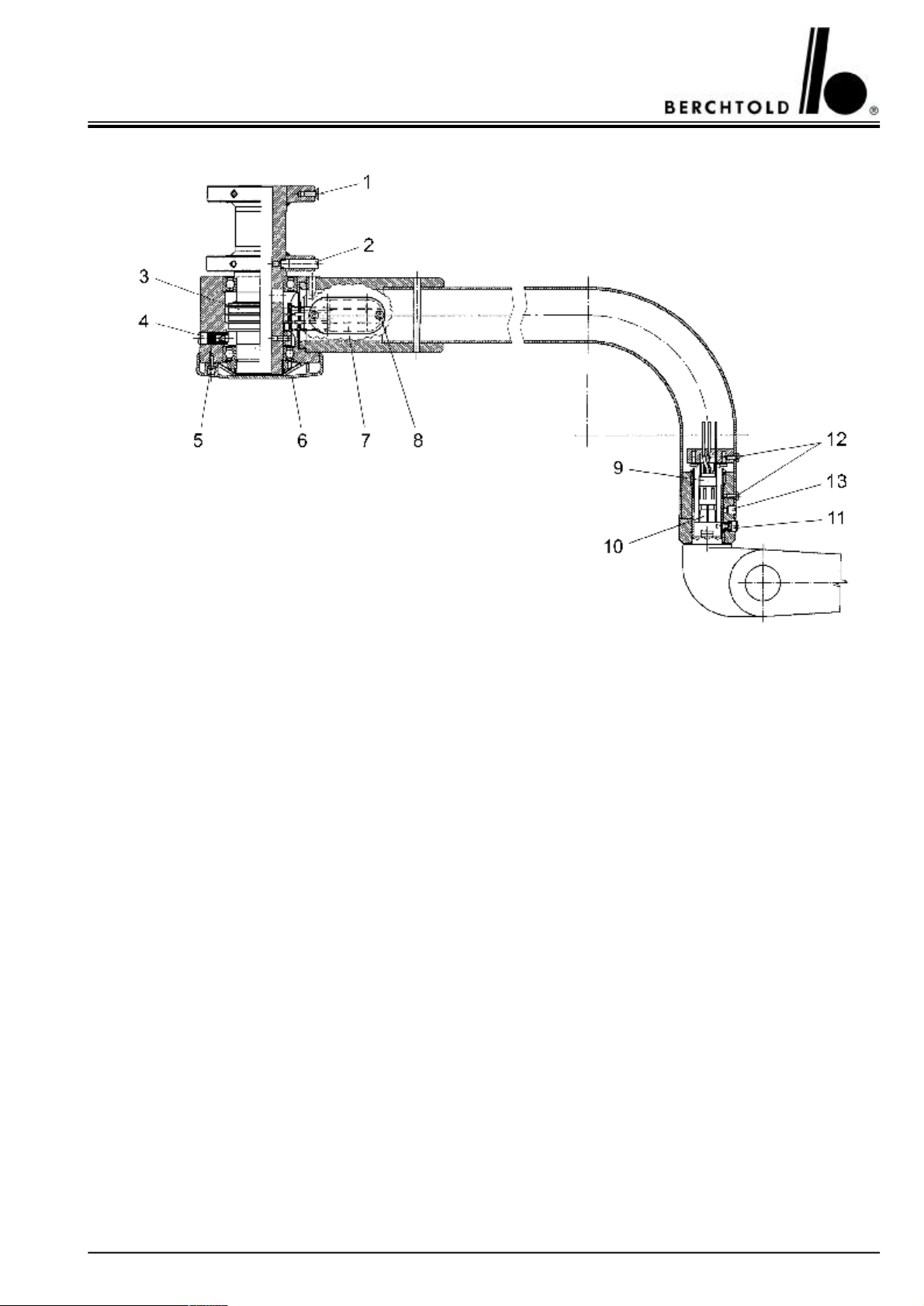
15 x Hexagon socket countersunk head screw,
part no. 284, minimal torque 23 Nm
2Locking pin, part no. 641749Male sliding contact, part no. 65241
3Sliding contact, part no. 6418610Female sliding contact, part no. 20002
4Brake screw, part no. 3882111Brake screw, part no. 64103
82 x cross recessed countersunk head screw,
part no. 235
5Cross recessed oval-head screw,
part no. 277
and distance sleeve, part no. 64783
6Cover, part no. 6417113Mortise screw, part no. 64126
7Contact block for sliding contacts, part no. 39693
12Cross recessed oval-head screw,
part no. 45396
43
Page 44
CHROMOPHARE® D 650plus, D 530plus, D 500plus, D 650, D 530, D 500 Service Manual (E)
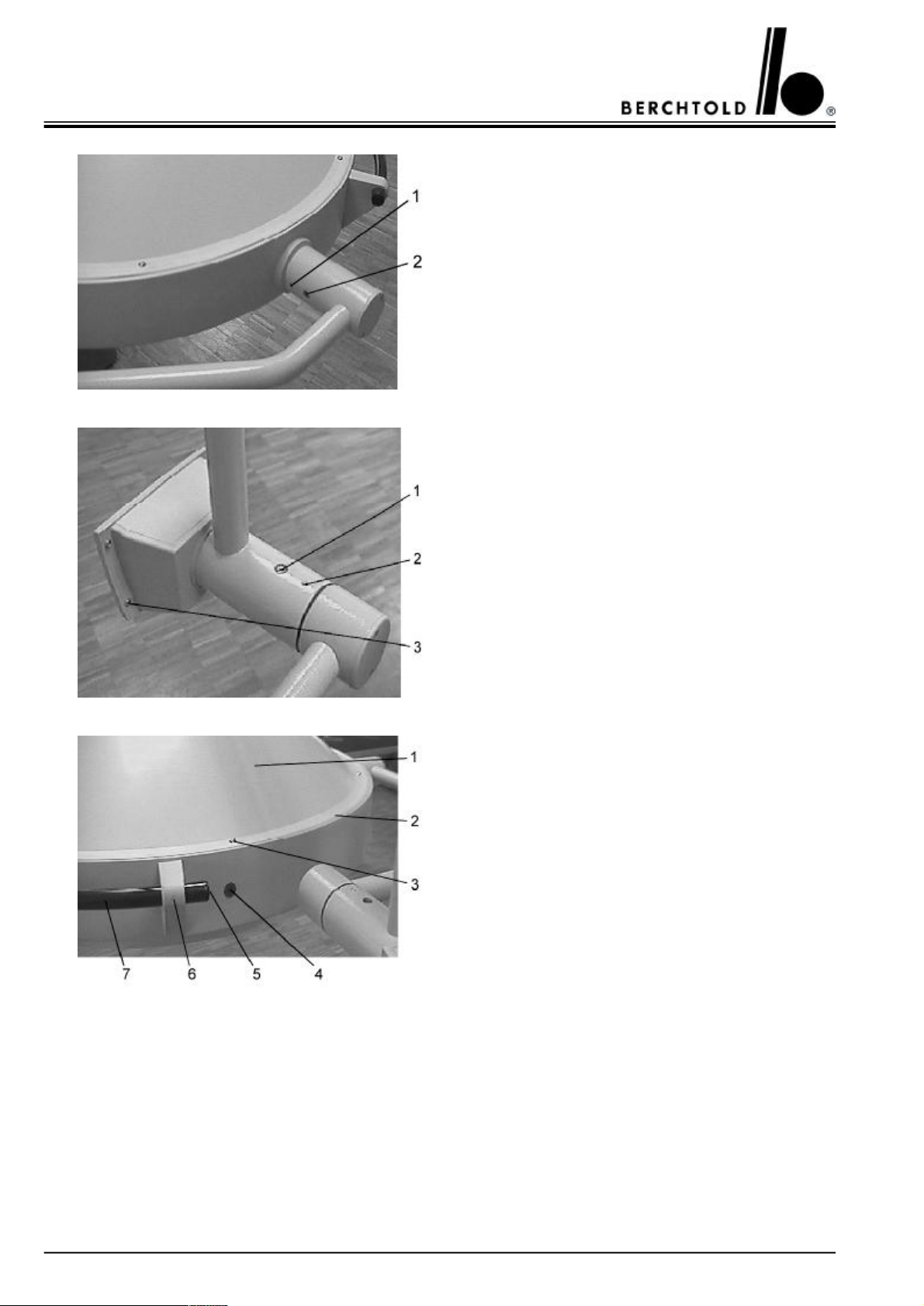
1Brake screw, part no. 42805
2Security screw, part no. 43009
1Security screw, part no. 43009
2Brake screw, part no. 42803
3Ejot screw, part no. 64669
1Hood D 650plus, D 650, part no. 64101
Hood D 530plus, D 500plus, D 530, D 500
part no. 66333
2Sealing rubber D 650plus, D 650, part no. 64677
Sealing rubber D 530plus, D 500plus, D 530 D 500,
part no. 66452
3Screw, part no. 64235
4Indication lamp, yellow, with cable and connector
part no. 65637
5Cover D650plus, D 530plus D 650, D 530,
part no. 51135
6Rail holder D650plus, D 530plus D 650, D 530,
part no. 62252
7Rail D 650plus, D 530plus, part no. 64145
Rail D 530plus, D 530, part no. 66330
44
Page 45
CHROMOPHARE® D 650plus, D 530plus, D 500plus, D 650, D 530, D 500 Service Manual (E)
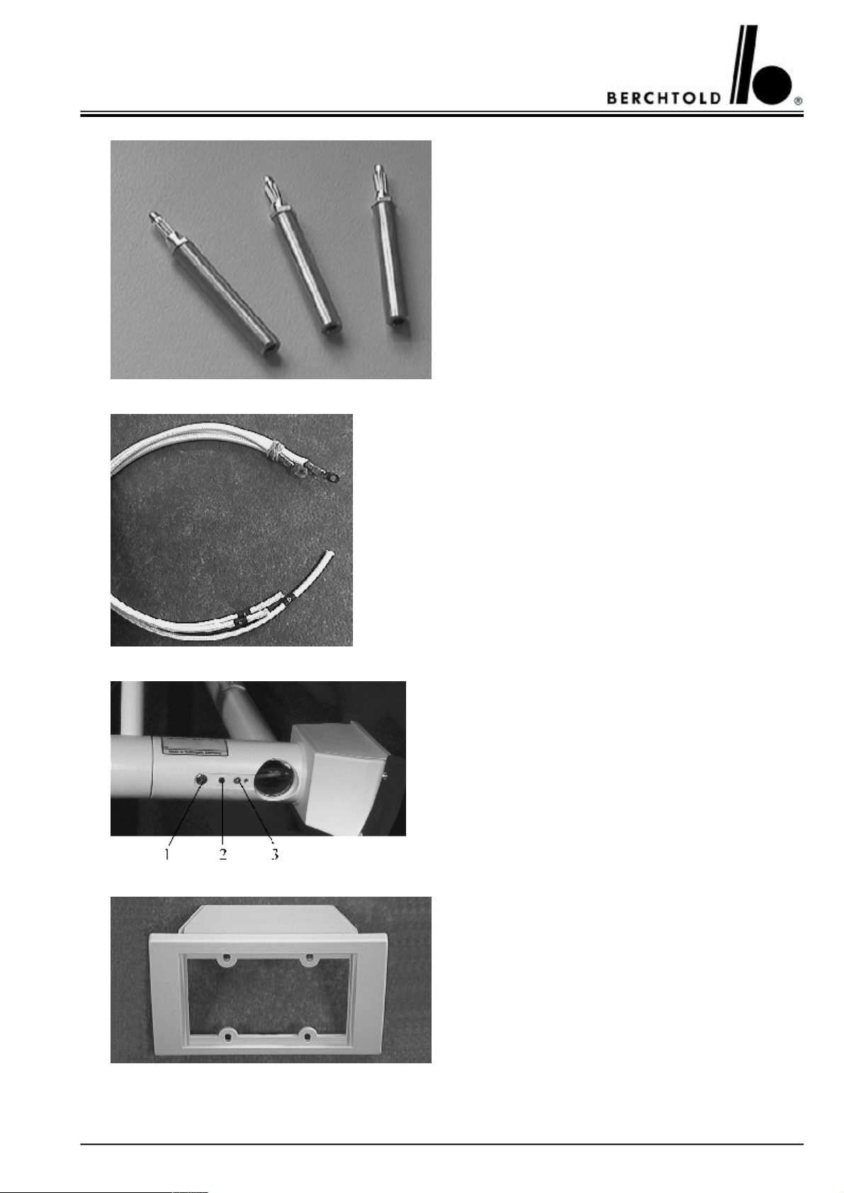
Test adapter for check of the halogen bulb supply voltage and check of the switch over function to reserve
bulb
part no. 50574
Wiring harness, from electronic to reflector connector,
part no. 65769
1Screw, part no. 68071
2Brake screw M5x5, part no. 68072
3Countersunk head screw M3x12, part no. 68073
Front part for touch control board, part no. 62402
45
Page 46
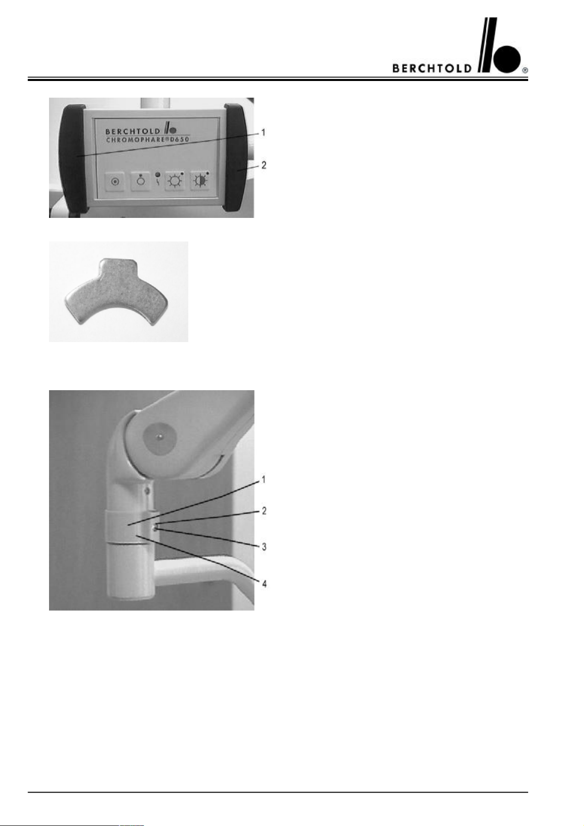
CHROMOPHARE® D 650plus, D 530plus, D 500plus, D 650, D 530, D 500 Service Manual (E)
8.2 CHROMOPHARE® D 650plus, D 650
1Bumper left, part no. 66320
2Bumper right, part no. 66319
Security lock – spring balanced arm, part no. 20010
1Protection bush, part no. 20011
2Washer, part no. 24197
3Screw, part no. 11656
4Security lock – spring balanced arm, (not visible)
part no. 20010
46
Page 47
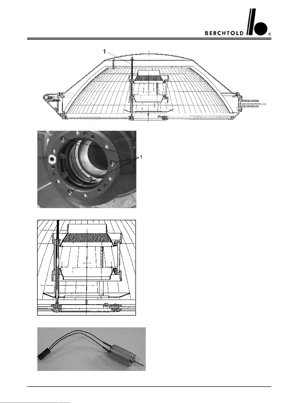
CHROMOPHARE® D 650plus, D 530plus, D 500plus, D 650, D 530, D 500 Service Manual (E)
1Guiding rod, with pressed socket for banana plug dia.
4 mm
part no. 64778
Filter glass assembly D 650plus, part no 68618
Filter glass assembly D 650, part no. 64157
D.C. motor with cable and connector, mounted in the
focusing mechanism,
part no. 67998
47
Page 48
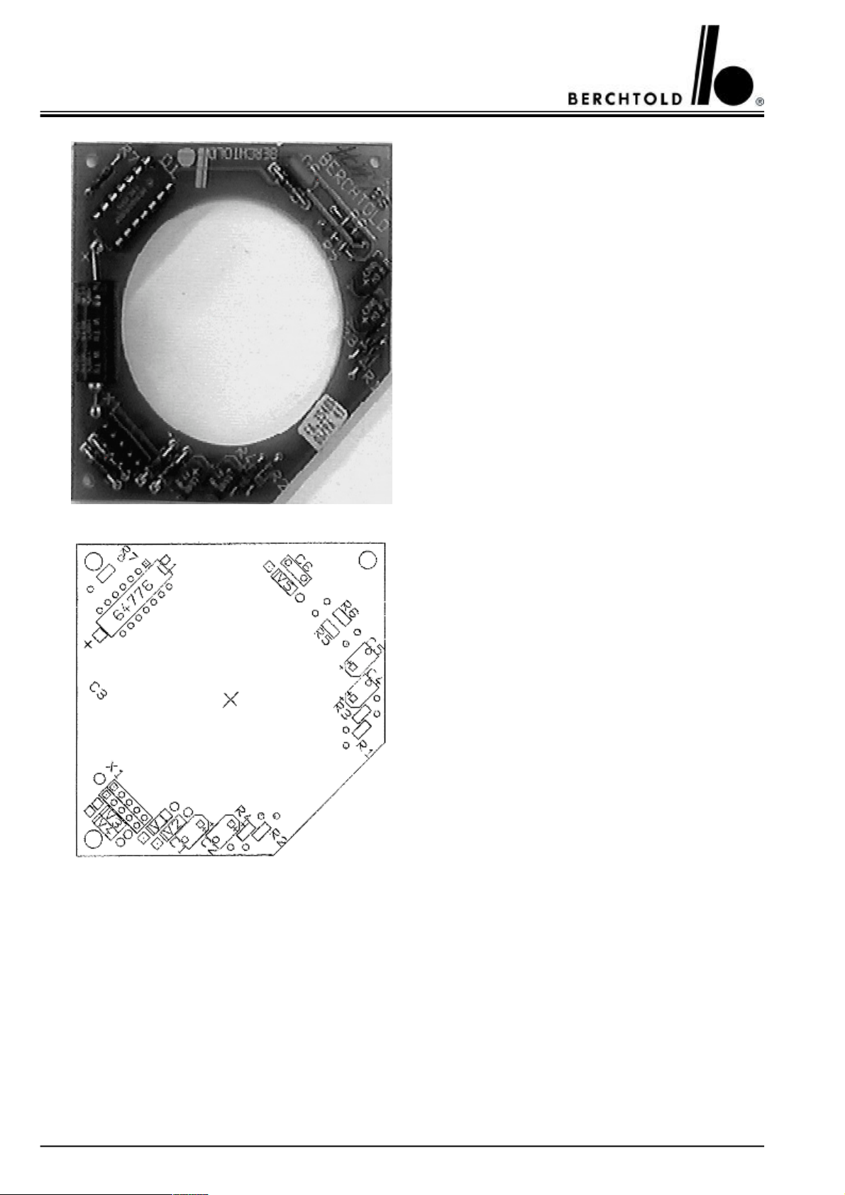
CHROMOPHARE® D 650plus, D 530plus, D 500plus, D 650, D 530, D 500 Service Manual (E)
Control circuit board for centre positioning of main
bulb,
part no. 64176
48
Page 49
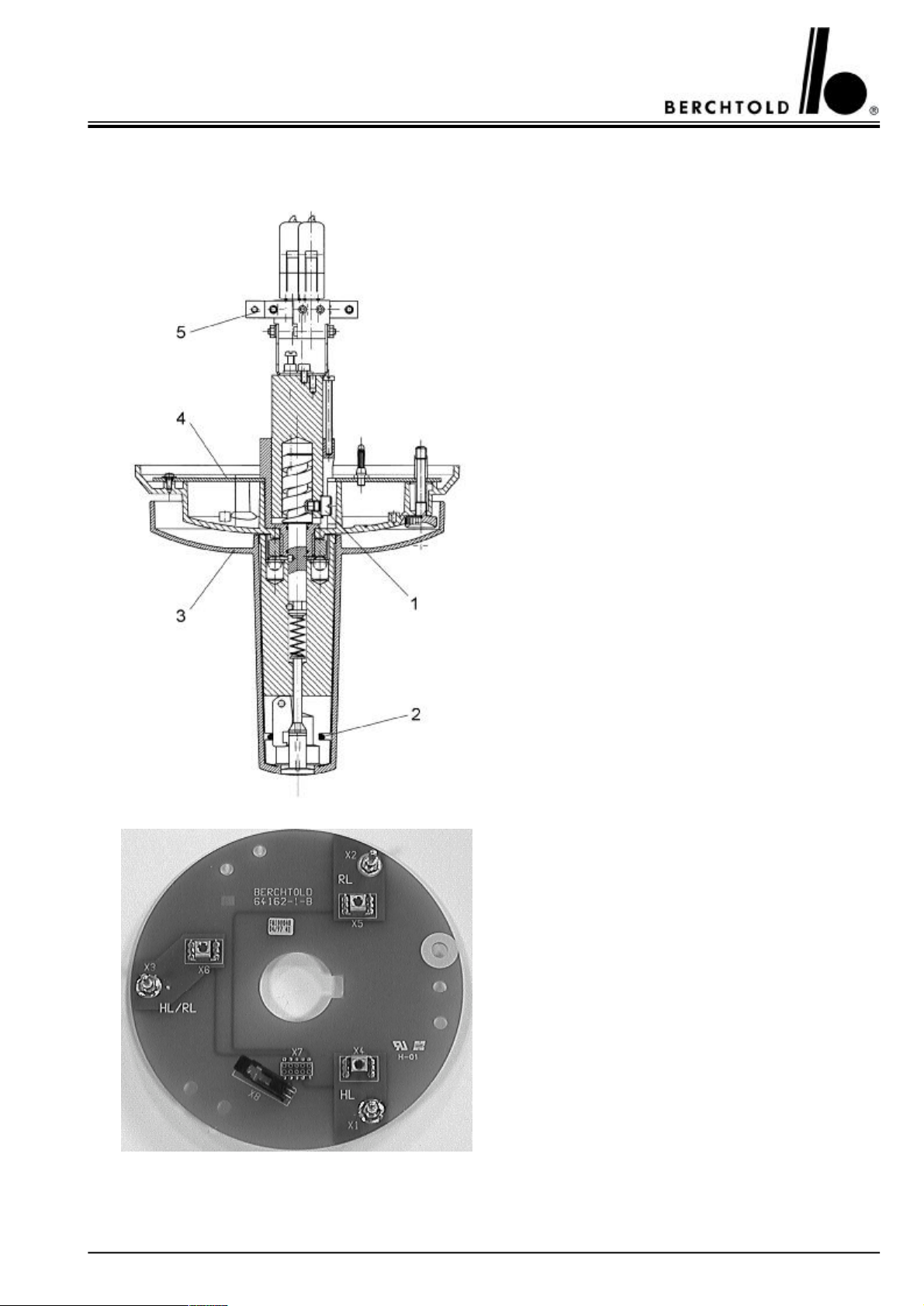
CHROMOPHARE® D 650plus, D 530plus, D 500plus, D 650, D 530, D 500 Service Manual (E)
8.3 CHROMOPHARE® D 650plus, D 650 version Standard and EndoLite®
Focusing mechanism for Standard and EndoLite®
without halogen bulbs, part no. 64163
1Guiding screw, part no. 64152
2O-ring, part no. 64203
3Cover, part no. 62418
4Connection board Standard, part no. 64162
5Holder for bulb with connecting cables without
halogen bulbs, part no. 64146
Connection board Standard, part no. 64162
HL = Main bulb
RL = Reserve bulb
HL/RL = Main and reserve bulb
49
Page 50
CHROMOPHARE® D 650plus, D 530plus, D 500plus, D 650, D 530, D 500 Service Manual (E)
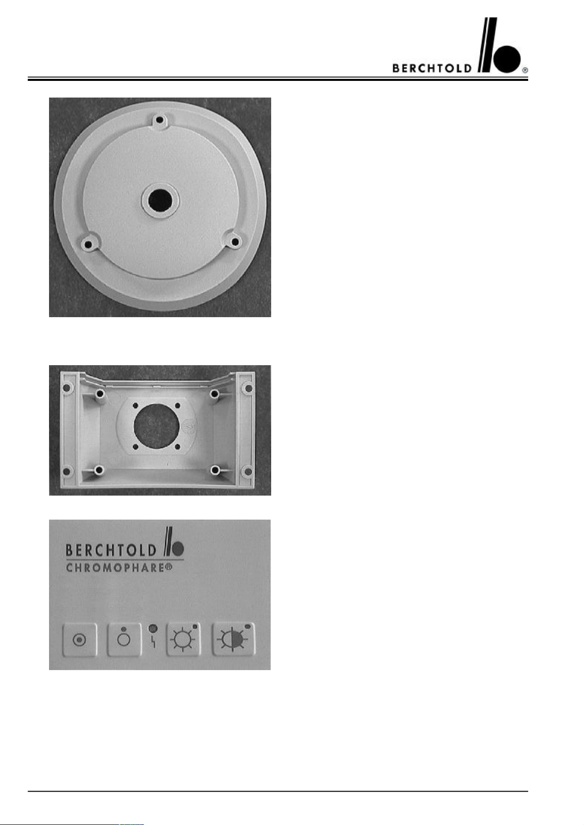
Cover, part no. 62418
8.4 CHROMOPHARE® D 650plus, D 530plus, D 650, D 530
Housing for touch control board, part no. 62407
50
Touch control board with foil for Standard,
part no. 68823
Page 51
CHROMOPHARE® D 650plus, D 530plus, D 500plus, D 650, D 530, D 500 Service Manual (E)
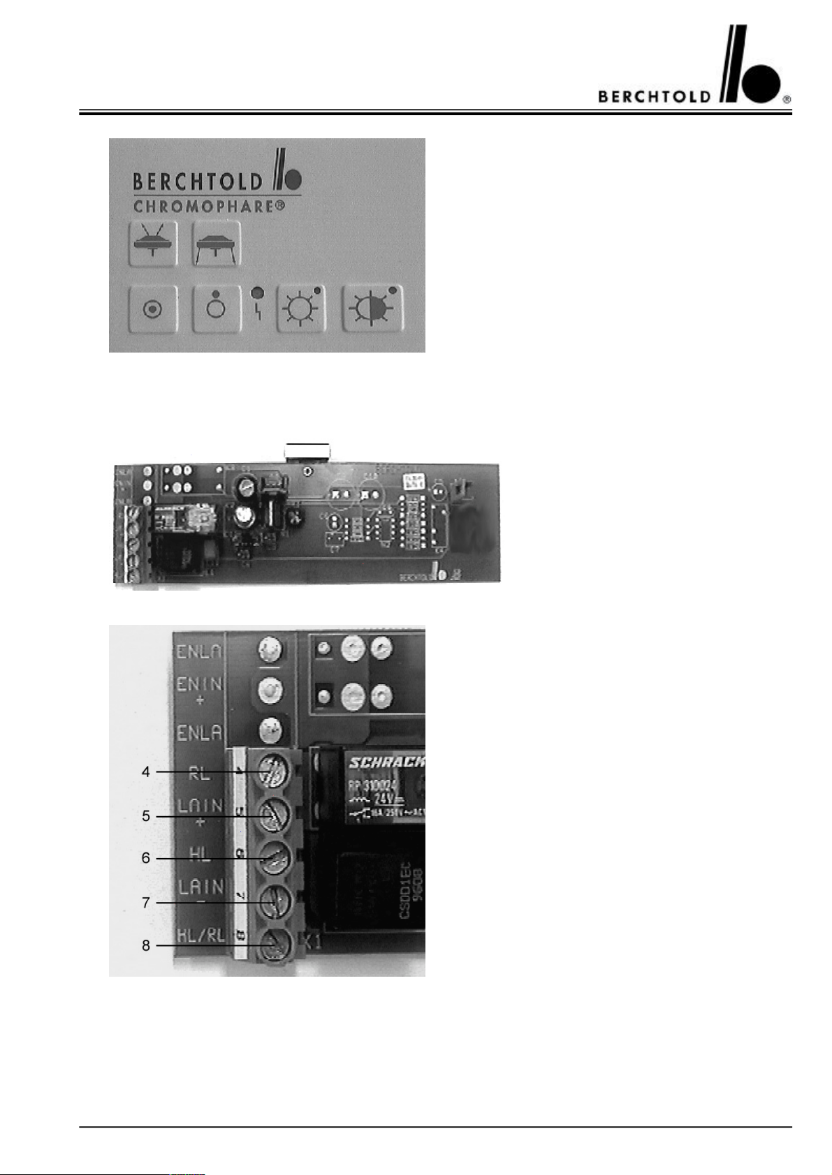
Touch control board with foil for Standard with
EndoLite®
part no. 68824
8.5 CHROMOPHARE® D 650plus, D 530plus, D 650, D 530 version Standard without EndoLite®
Reserve bulb switch over circuit board
without EndoLite®
(mounted in the light body)
part no. 65610
4to reserve bulb (RL)
5(+) input, coming from light intensity power
circuit board (LAIN +)
6to main bulb (HL)
7(-) input, coming from light intensity power circuit
board (LAIN -)
8common cable to main and reserve bulb (HL/RL)
51
Page 52
CHROMOPHARE® D 650plus, D 530plus, D 500plus, D 650, D 530, D 500 Service Manual (E)
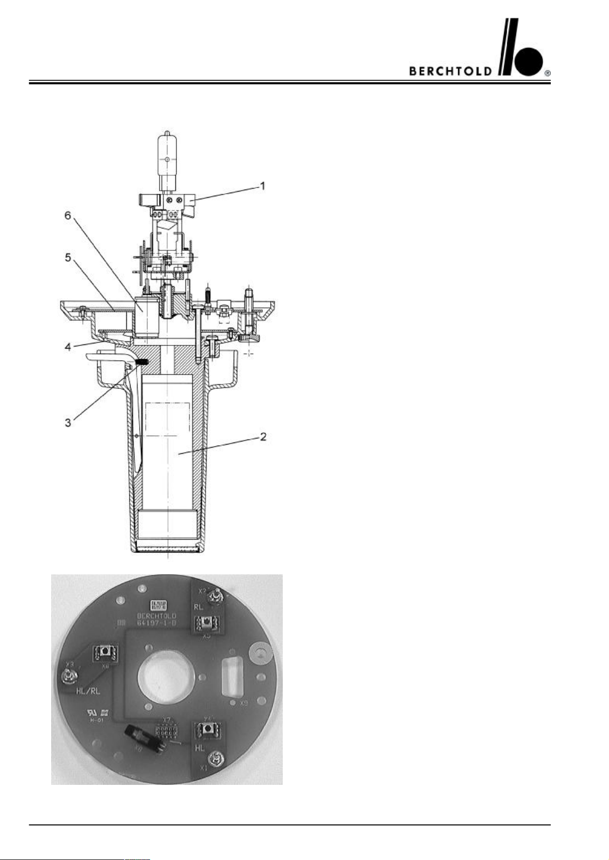
8.6 CHROMOPHARE® D 650plus, D 650 version light field plotting model LFN
Focusing mechanism for LFN and LFN with
EndoLite® without halogen bulbs,
part no. 64673
1Holder for bulb with connecting cables without
halogen bulbs, part no. 64146
2IR-module, part no. 65643
3Pressure spring, part no. 45173
4Cover, part no. 64194
5connection board for LFN, part no. 64197
6D.C. motor, part no. 67998
Connection board for LFN or CCD, part no. 64197
HL = Main bulb
RL = Reserve bulb
HL/RL = Main and reserve bulb
52
Page 53
CHROMOPHARE® D 650plus, D 530plus, D 500plus, D 650, D 530, D 500 Service Manual (E)
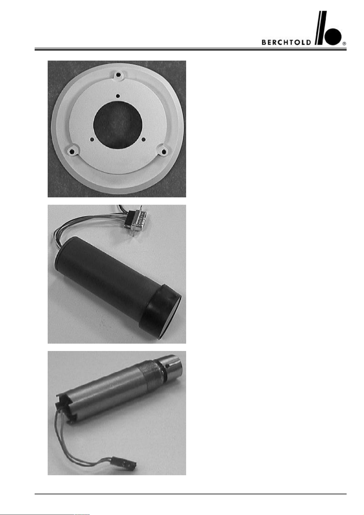
Cover, part no. 64194
IR-module, part no. 65643
Motor for LFN, part no. 54860
53
Page 54
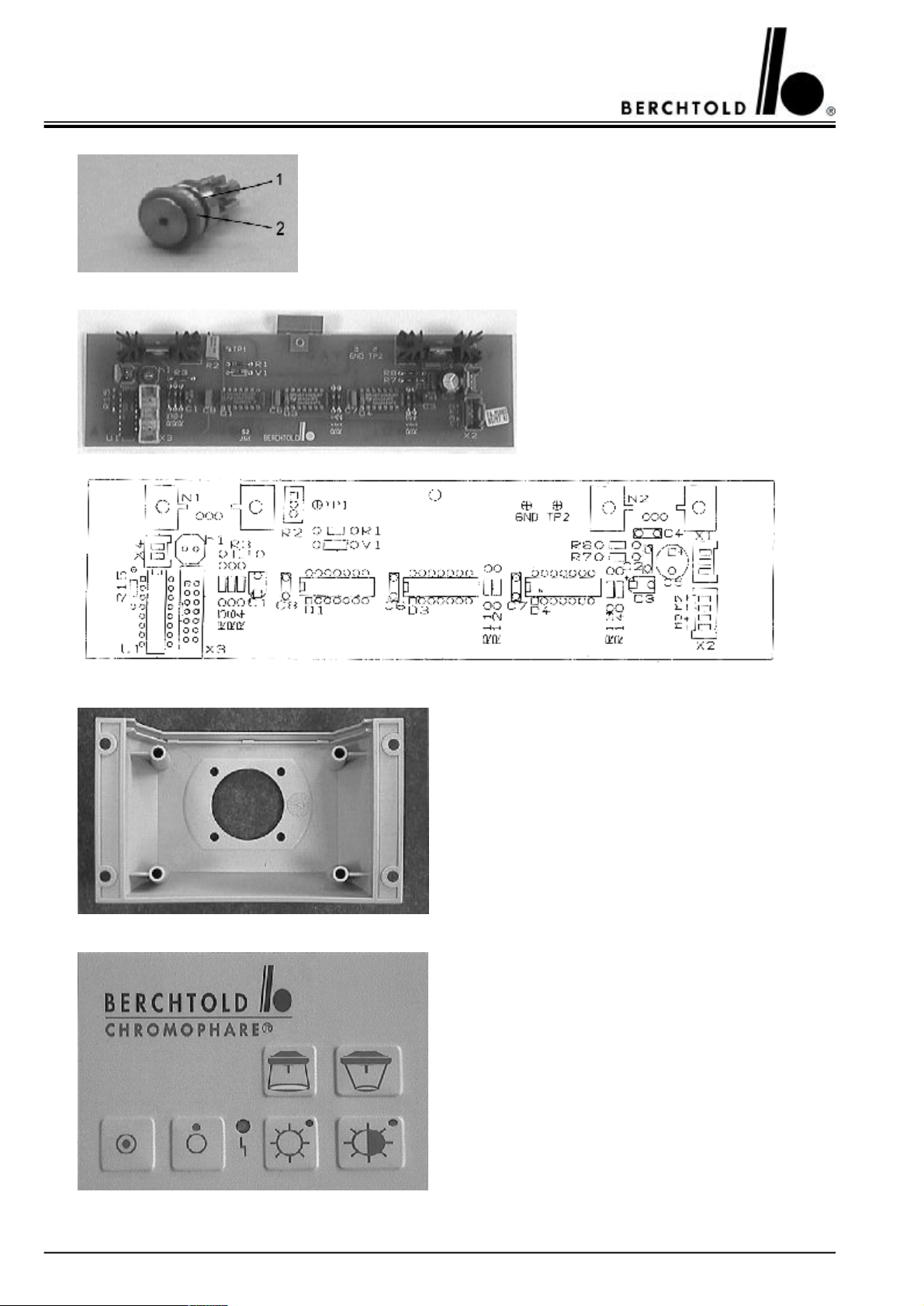
CHROMOPHARE® D 650plus, D 530plus, D 500plus, D 650, D 530, D 500 Service Manual (E)
1Gearwheel, part no. 54849
2Ring for sliding clutch, part no. 54809
LFN control, part no. 65608
Housing for touch control board for LFN and
LFN with EndoLite®
part no. 62401
Touch control board with foil for LFN part no. 68825
54
Page 55
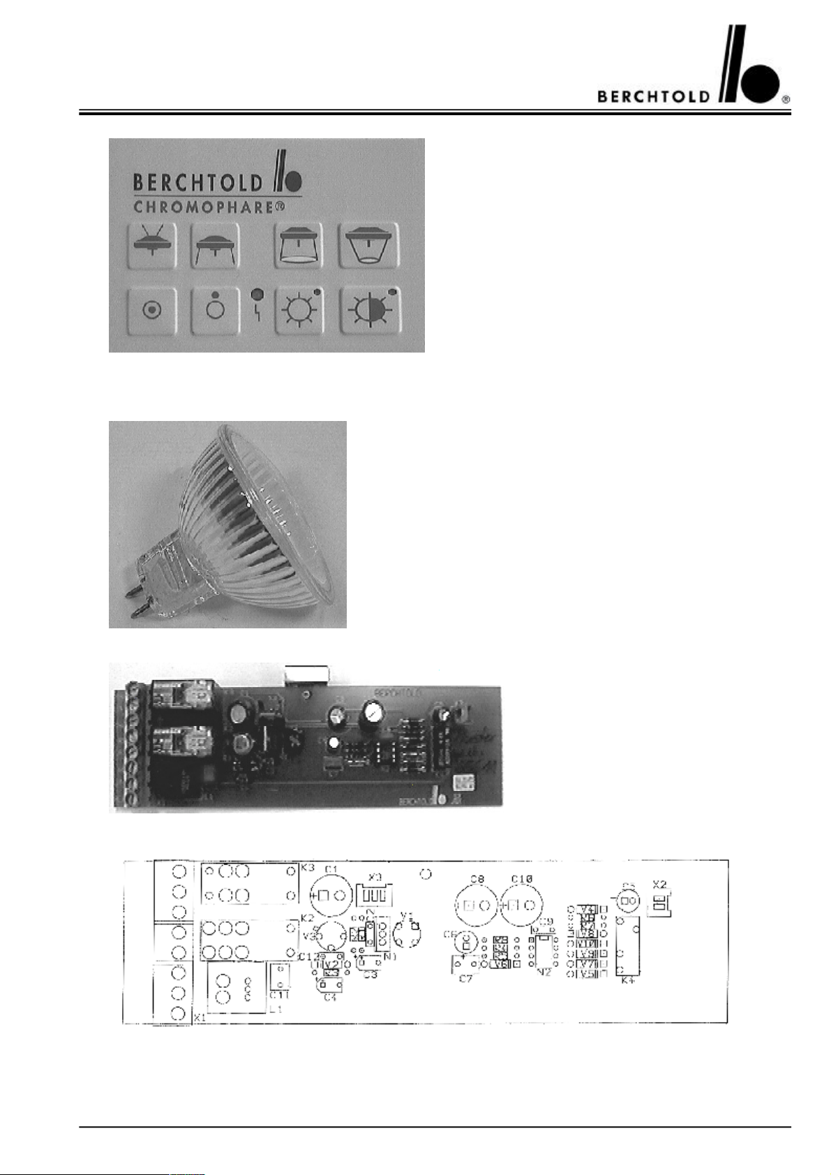
CHROMOPHARE® D 650plus, D 530plus, D 500plus, D 650, D 530, D 500 Service Manual (E)
Touch control board with foil for LFN with EndoLite®
part no. 68826
8.7 CHROMOPHARE® D 650plus, D 530plus, D 650, D 530 version with EndoLite®
EndoLite®, spare bulb 12V/20W, with glass disc and
reflector,
part no. CZ 960-12
Reserve bulb switch over circuit board
with EndoLite®
(mounted in the light body)
part no. 65611
55
Page 56
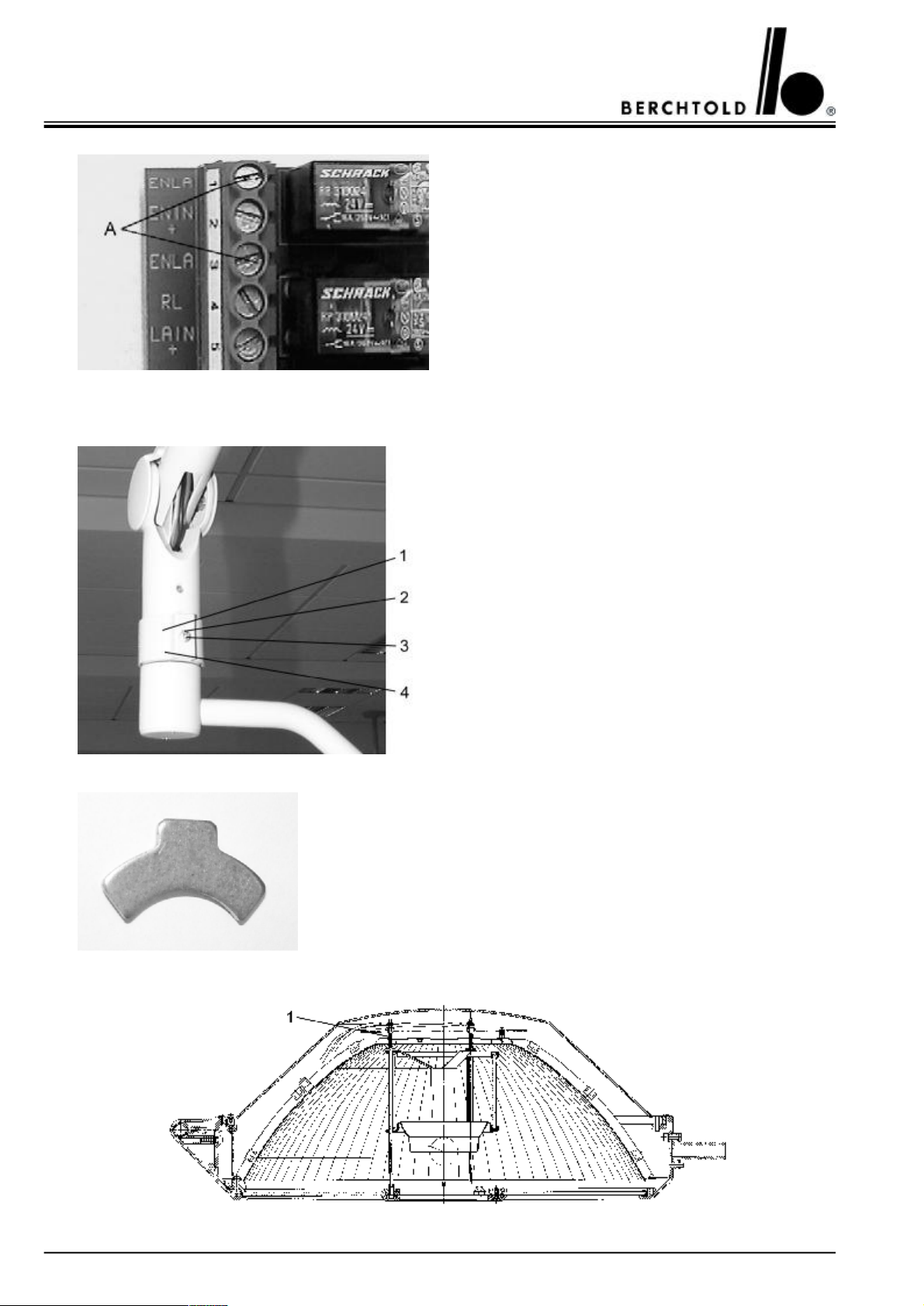
CHROMOPHARE® D 650plus, D 530plus, D 500plus, D 650, D 530, D 500 Service Manual (E)
Ato EndoLite®, max. 11,0 V A.C. / D.C.
8.8 CHROMOPHARE® D 530plus, D 500plus, D 530, D 500
1Protection bush, part no. 20011
2Washer, part no. 24197
3Screw, part no. 11656
4Security lock – spring balanced arm, (not visible)
part no. 20010
Security lock – spring balanced arm, part no. 20010
56
Page 57
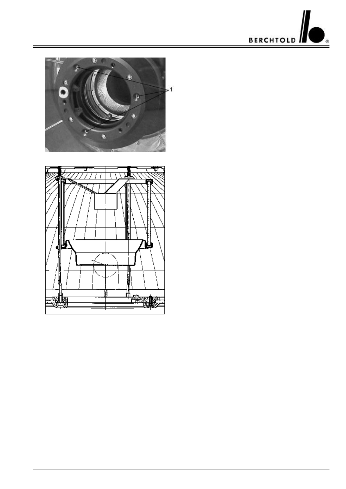
CHROMOPHARE® D 650plus, D 530plus, D 500plus, D 650, D 530, D 500 Service Manual (E)
1 D 530plus, D 530:
Guiding rod, with pressed socket for banana plug dia.
4 mm
part no. 66406
D 500plus, D 500:
Guiding rod, with pressed socket for banana plug dia.
4 mm
part no. 66405
D 530plus, D 530:
filter glass assembly, part no. 66409
D 500plus, D 500:
filter glass assembly, part no. 66457
57
Page 58
CHROMOPHARE® D 650plus, D 530plus, D 500plus, D 650, D 530, D 500 Service Manual (E)
8.9 CHROMOPHARE® D 530plus, D 530 version Standard and EndoLite®
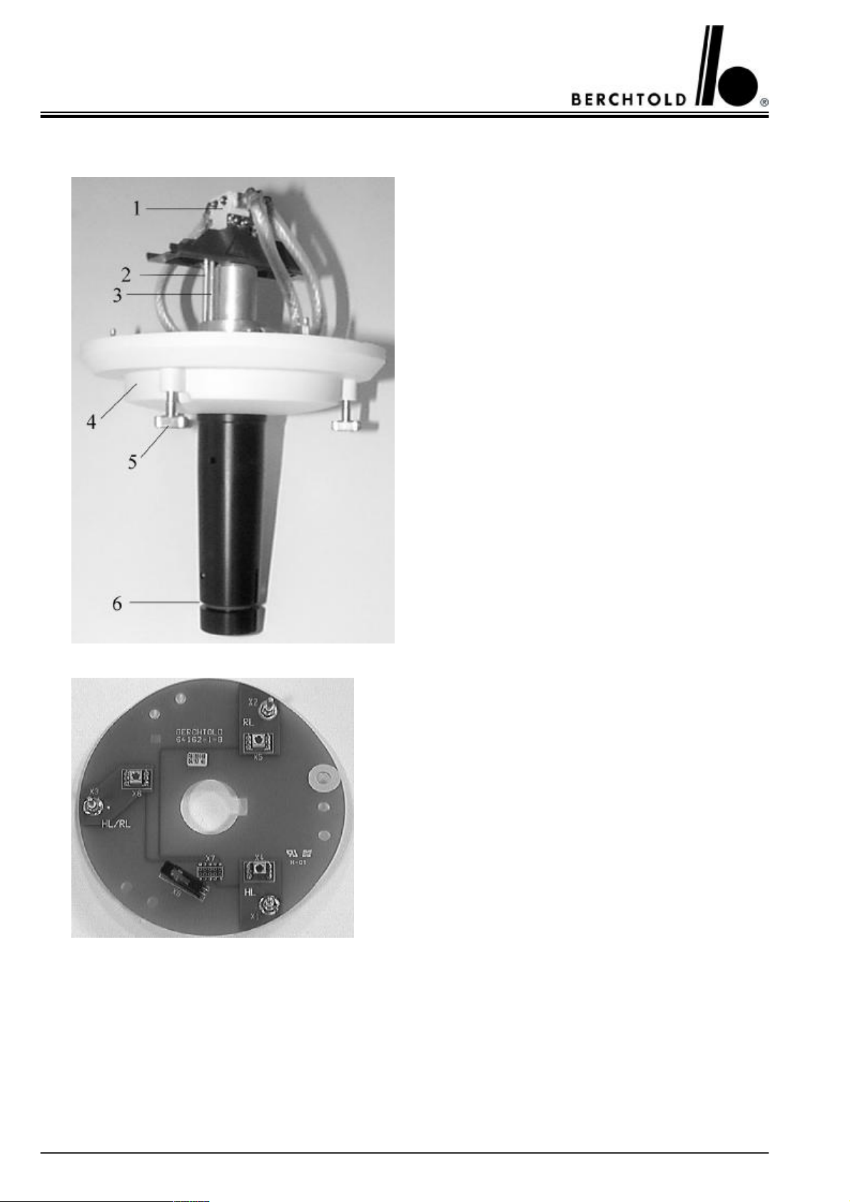
Focusing mechanism for Standard and EndoLite®
without halogen bulbs, part no.66421
1Holder for bulb, part no. 64146
2Screw, lower stop, part no. 66422
3Screw, upper stop, part no. 66423
4Cover, part no. 62418
5Knurled screw, part no. 64142
6O-ring, part no. 64203
Connection board for Standard, part no. 64162
HL = Main bulb
RL = Reserve bulb
HL/RL = Main and reserve bulb
58
Page 59
CHROMOPHARE® D 650plus, D 530plus, D 500plus, D 650, D 530, D 500 Service Manual (E)
8.10 CHROMOPHARE® D 500plus, D 500 version Standard
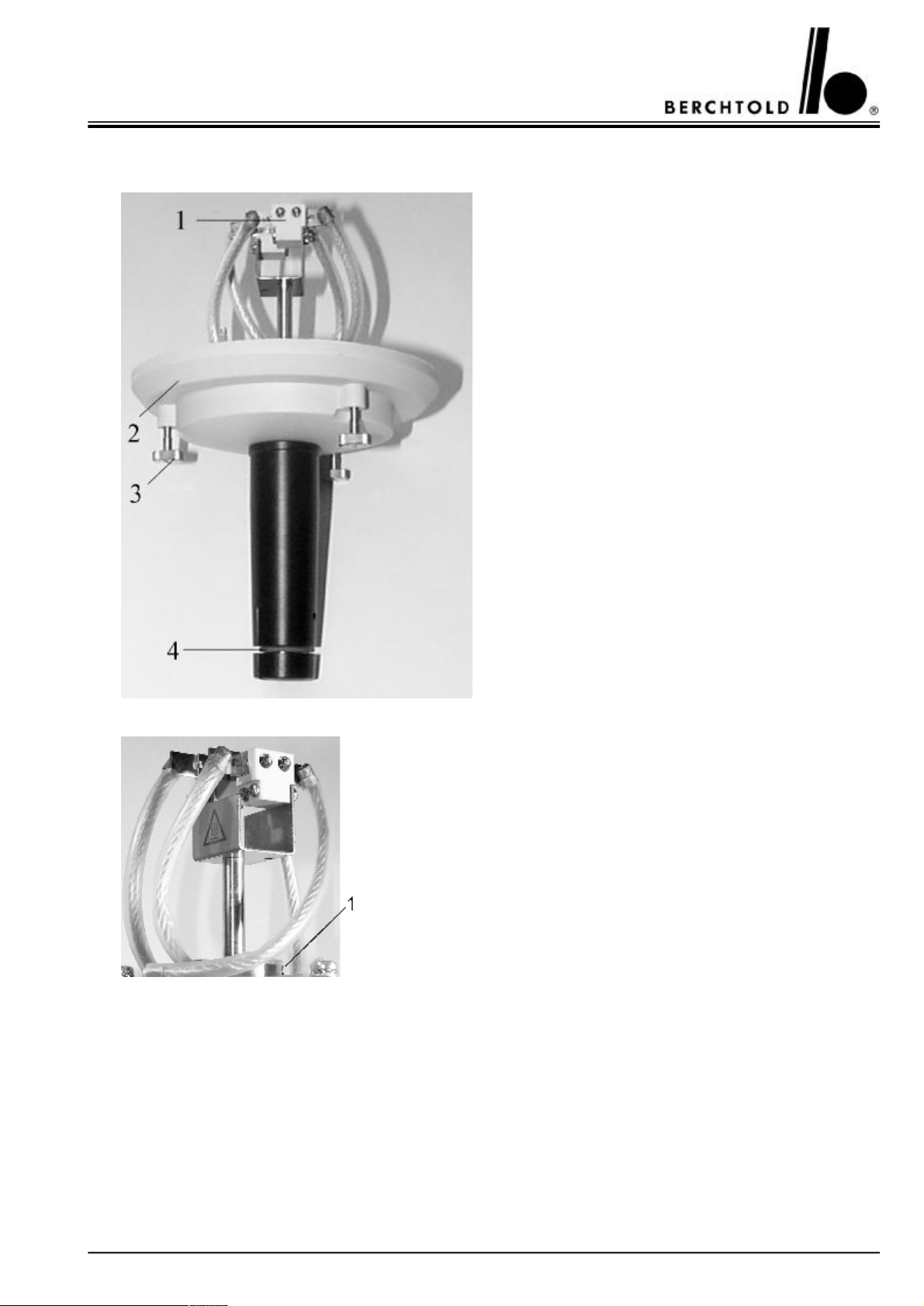
Focusing mechanism for Standard without halogen
bulbs, part no. 66419
1Holder for bulb, part no. 64146
2Cover, part no. 64418
3Knurled screw, part no. 64142
4O-ring, part no. 64203
Focusing mechanism D 500plus, D 500
1Threaded rod, part no. 38593
59
Page 60
CHROMOPHARE® D 650plus, D 530plus, D 500plus, D 650, D 530, D 500 Service Manual (E)
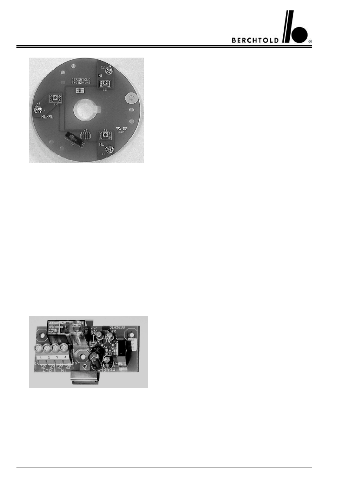
Connection board for Standard, part no. 64162
HL = Main bulb
RL = Reserve bulb
HL/RL = Main and reserve bulb
1Touch control board for D 500plus, D 500,
part no. 66417
2Housing for touch control board for D 500plus,
D 500, part no. 66416
3Countersunk-head screw M3x16, part no. 103
Circuit board On/Off for D 500plus, D 500,
part no. 68015
60
Page 61
CHROMOPHARE® D 650plus, D 530plus, D 500plus, D 650, D 530, D 500 Service Manual (E)
9.TEST AND ADJUSTMENT POINTS
9.1 Test points CHROMOPHARE® D 650
TP 1 Terminal block 24 V D.C. loaded, tolerance + 1.5 / - 0.3 V
TP 2 Sliding contact 24 V D.C. loaded, tolerance + 1.5 / - 0.3 V
TP 3 Sliding ring 23.8 V D.C. loaded, tolerance + 1.5 / - 0.3 V
TP 4 Sliding ring 23.6 V D.C. unloaded, tolerance + 1.5 / - 0.3 V
TP 5 Cable connectors input X1/2 to X1/4 22.6 V A.C. / D.C., tolerance + 1.5 / - 0.3 V
TP 6 Main bulb between cable 8 and 6 max. 22.0 V A.C. / D.C. RMS, tolerance + 0.3 V
Setting of the max. bulb voltage see page 63 - 64, by means of adjustable resistor R 20
9.2 Test points CHROMOPHARE® D 650plus, D 530plus, D 500plus, D 530, D 500
TP 1 Terminal block 24 V D.C. loaded, tolerance + 1.5 / - 0.3 V
TP 2 Sliding contact 24 V D.C. loaded, tolerance + 1.5 / - 0.3 V
TP 3 Sliding ring 23.8 V D.C. loaded, tolerance + 1.5 / - 0.3 V
TP 4 Sliding ring 23.6 V D.C. unloaded, tolerance + 1.5 / - 0.3 V
TP 5 Cable connectors input X1/2 to X1/4 23.3 V A.C. / D.C., tolerance + 1.5 / - 0.3 V
TP 6 Main bulb between cable 8 and 6 max. 22.8 V A.C. / D.C. RMS, tolerance + 0.3 V
Setting of the max. bulb voltage see page 63 - 64, by means of adjustable resistor R 20
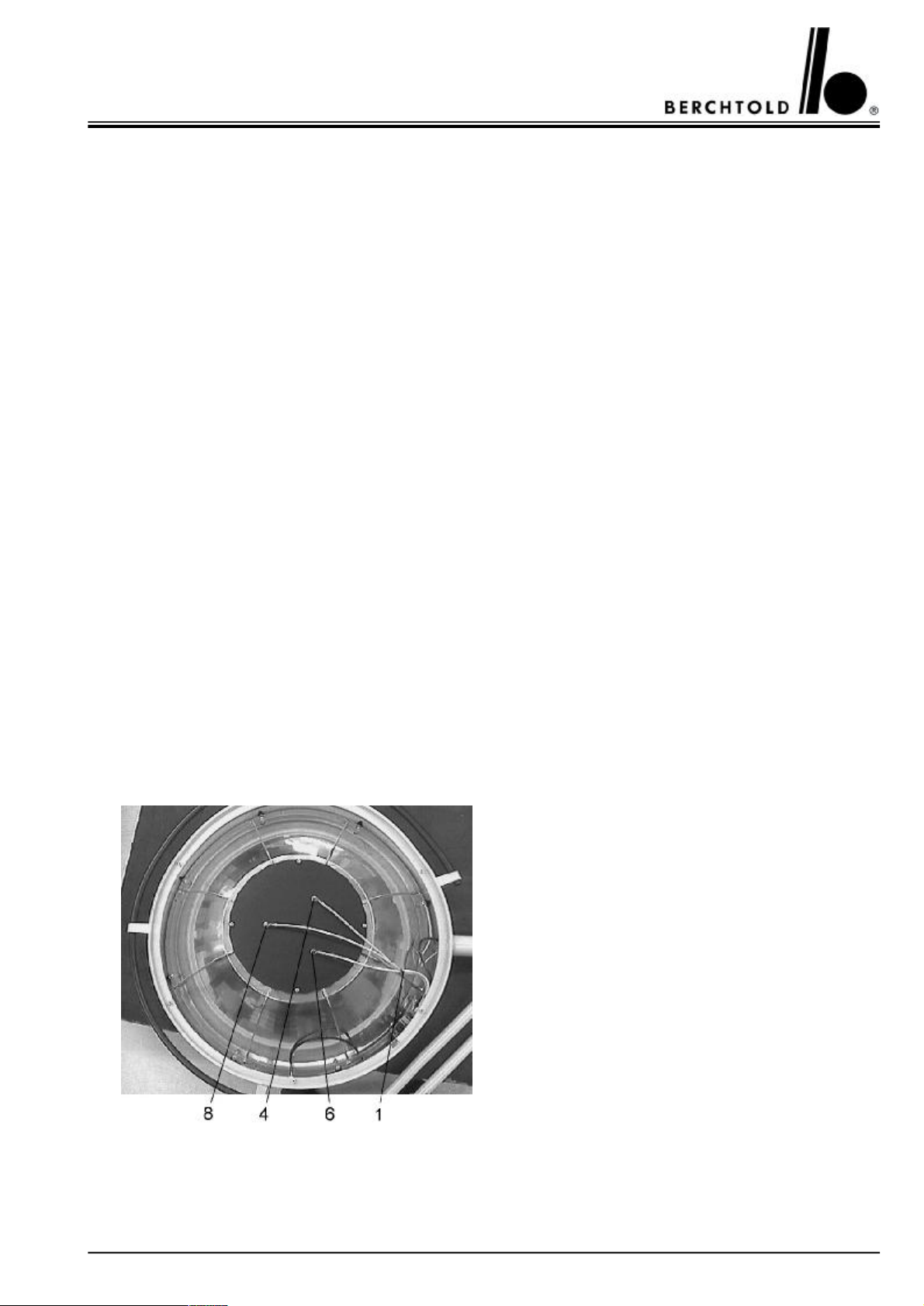
1Wiring harness, from electronic to reflector con-
nector,
part no. 65769
6Connection to main bulb, marked with 6
4Connection to reserve bulb, marked with 4
8Common connection to main and reserve bulb,
marked with 8
61
Page 62
CHROMOPHARE® D 650plus, D 530plus, D 500plus, D 650, D 530, D 500 Service Manual (E)
9.3.1CHROMOPHARE® D 650plus, D 650
(classic cardanic)
BBrake screwFSpring adjustment, see page 65 - 66
TPTest points, see page 59HBHeight movement, see page 66
9.3.3 CHROMOPHARE® D 650plus/530plus, D 650/530 (classic cardanic)
9.3.2CHROMOPHARE® D 650plus, D 650
(flat cardanic)
BBrake screwFSpring adjustment, see page 65 - 66
TPTest points, see page 59HBHeight movement, see page 66
62
Page 63
CHROMOPHARE® D 650plus, D 530plus, D 500plus, D 650, D 530, D 500 Service Manual (E)
9.3.4 CHROMOPHARE® D 650plus/530plus, D 650/530 (flat Kardanik)
BBrake screwFSpring adjustment, see page 65 - 66
TPTest points, see page 59HBHeight movement, see page 66
9.3.5CHROMOPHARE® D 530plus, D 530
(classic cardanic)
BBrake screwFSpring adjustment, see page 65 - 66
TPTest points, see page 59HBHeight movement, see page 66
9.3.6CHROMOPHARE® D 530plus, D 530
(flat cardanic)
63
Page 64
CHROMOPHARE® D 650plus, D 530plus, D 500plus, D 650, D 530, D 500 Service Manual (E)
9.3.7CHROMOPHARE® D 500plus, D 500
(classic cardanic)
BBrake screwFSpring adjustment, see page 65 - 66
TPTest points, see page 59HBHeight movement, see page 66
9.3.9 CHROMOPHARE® D 530plus/530plus, D 530/530 (classic cardanic)
9.3.8CHROMOPHARE® D 500plus, D 500
(flat cardanic)
BBrake screwFSpring adjustment, see page 65 - 66
TPTest points, see page 59HBHeight movement, see page 66
64
Page 65
CHROMOPHARE® D 650plus, D 530plus, D 500plus, D 650, D 530, D 500 Service Manual (E)
9.3.10 CHROMOPHARE® D 530plus/530plus, D 530/530 (flat cardanic)
BBrake screwFSpring adjustment, see page 65 - 66
TPTest points, see page 59HBHeight movement, see page 66
9.4Adjustment points for halogen bulb and EndoLite® bulb voltage
(only D 650plus, D 530plus, D 650, D 530)
Back side of touch control boardPart no. 68823
Part no. 68824
Part no. 68825
Part no. 68826
S1Switch for Booster-switching. Switch of „on“
for setting the function.
(only D 650plus, D 650).
S2Switch has no function
R20Adjustable resistor for setting the max. halogen
bulb voltage
D 650:
22,0 V A.C. und D.C. RMS tolerance +0.3 Volt
D 650plus, D 530plus, D 530:
22,8 V A.C. und D.C. RMS tolerance +0.3 Volt
R21Adjustable resistor for setting the EndoLite®
bulb voltage
max. 11.0 V A.C. und D.C. RMS, -1 Volt
tolerance
65
Page 66

CHROMOPHARE® D 650plus, D 530plus, D 500plus, D 650, D 530, D 500 Service Manual (E)
Attention:
For correct bulb voltage setting please notice!
If the light intensity power circuit board is installed in separate wall box please take also the voltage drop of the
cable into consideration.
If the terminal voltage under load on the ceiling tube is higher than 24.5 V D.C. (main or supplementary supply),
an electronically alignment must be done. The reason for this is an exceeding of the allowed halogen lamp tension
(set-point 22.0 V +/- 0.2 V A.C./D.C.) because of the electronically aligned terminal voltage of 24.0 V. Changes
of the terminal voltage are not controlled and therefore affect the halogen lamp tension (life time, illumination).
If the terminal voltage under load on the ceiling tube is higher than 2.0 V D.C., the halogen lamp tension cannot
be aligned to the maximum allowed set-point.
The electronically alignment has first to be effected with emergency supply (D.C.). In this way, changes in the
illumination can be excluded. After having aligned, the main supply must be adjusted accordingly via transformer
taps.
How to proceed the D.C. alignment:
1. Switch on the emergency supply.
2. Switch on the light.
3. Measuring of the terminal voltage on the ceiling terminal (set-point 24.0 V D.C. under load).
4. Terminal voltage = 24.0 V D.C. (+0.3 V tolerance): no electronic alignment is necessary.
5. Terminal voltage > 24.3 V D.C.: adjusting of the halogen lamp tension to 22.2 V A.C./D.C. (+0.3 V tolerance)
on the measuring point „reflector connection“ on the back of the key board through adjustable resistor R 20 (see
page 65, the original boards are without component printing). As another measuring point, the terminals of the
power board X 1/2 and X 1/4 (part no. 65604) can be used. The alignment value through adjustable resistor R 20
on this measuring points amounts to 22.6 V A.C./D.C. (+0.3 V tolerance). Because of the voltage drop, the halogen lamp tension amounts to 22.0 V A.C./D.C. (+0.3 V tolerance) at D 650 and 22.8 V A.C./D.C. (+0.3 V tolerance) at D 650plus, D 530plus, D 530.
6. End of alignment respectively beginning of the transformer adjustment, see page 36.
66
Page 67
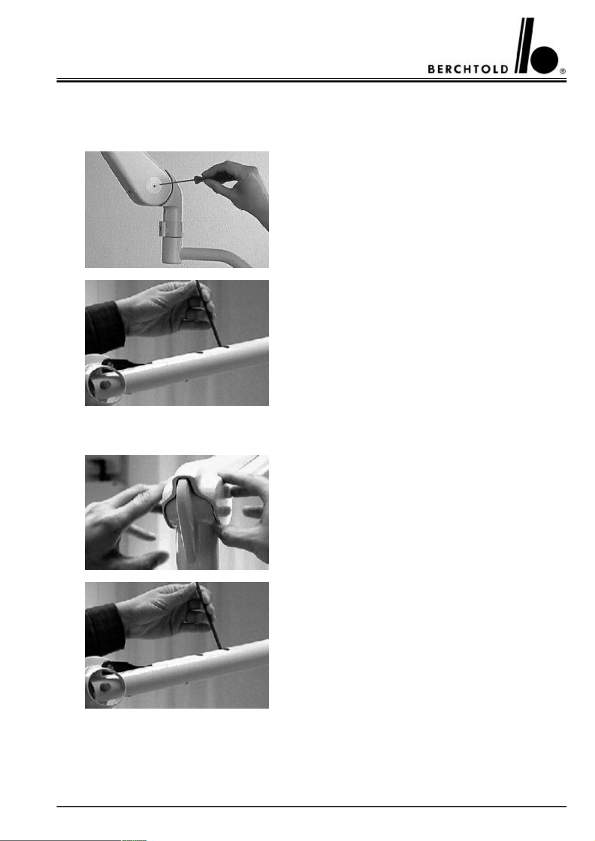
CHROMOPHARE® D 650plus, D 530plus, D 500plus, D 650, D 530, D 500 Service Manual (E)
10.ADJUSTMENT OF WEIGHT COMPENSATION ON THE SPRING ARM
10.1 CHROMOPHARE® D 650plus, D 650 (classic cardanic)
Remove both screws by using a 2 mm Allen key.
Loosen the covers of the spring-balanced support arm.
Adjustment:
Light head drifts upward:
Move the acrobat arm upward or downward as far as the circular nut becomes visible in one of the two windows. Turn this
circular nut with a steel pin, diameter 4 mm, in the direction of
the minus symbol.
Light head moves downward:
Turn the circular nut in the direction of the plus symbol.
10.2 CHROMOPHARE® D 530plus, D 500plus, D 530, D 500 (classic cardanic)
By pulling the round side caps slightly apart the main covering
hull can be lifted off of the spring arm.
Adjustment:
Light head drifts upward:
Move the acrobat arm upward or downward as far as the circular nut becomes visible in one of the two windows. Turn this
circular nut with a steel pin, diameter 4 mm, in the direction of
the minus symbol.
Light head moves downward:
Turn the circular nut in the direction of the plus symbol.
67
Page 68
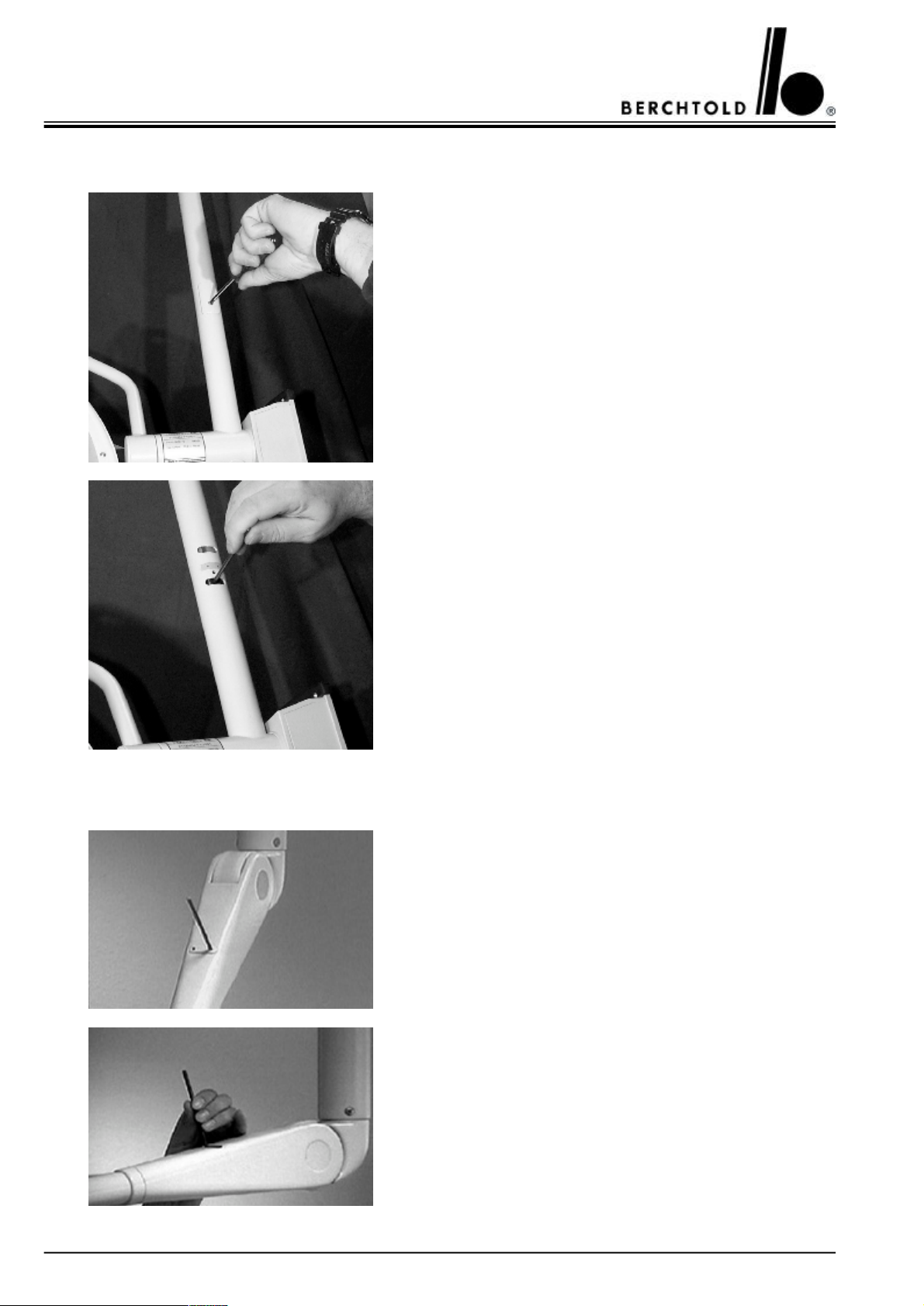
CHROMOPHARE® D 650plus, D 530plus, D 500plus, D 650, D 530, D 500 Service Manual (E)
10.3 CHROMOPHARE® D 650plus, D 530plus, D 500plus, D 650, D 530, D 500 (flat cardanic)
The spring arm can be adjusted to a horizontal position on a low
Remove the cover plate by using a Phillips screwdriver.
Adjustment:
Light head drifts upward:
Move the acrobat arm upward or downward as far as the circular nut becomes visible in one of the two windows. Turn this
circular nut with a steel pin, diameter 4 mm, in the direction of
the minus symbol.
Light head moves downward:
Turn the circular nut in the direction of the plus symbol.
11.ADJUSTMENT OF HEIGHT MOVEMENT ON THE SPRING ARM
ceiling.
Remove the cap.
Adjust the arm until the round nut in the groove becomes visible. Turn to the desired adjustment with a 4 mm dia. steel pin.
68
Page 69
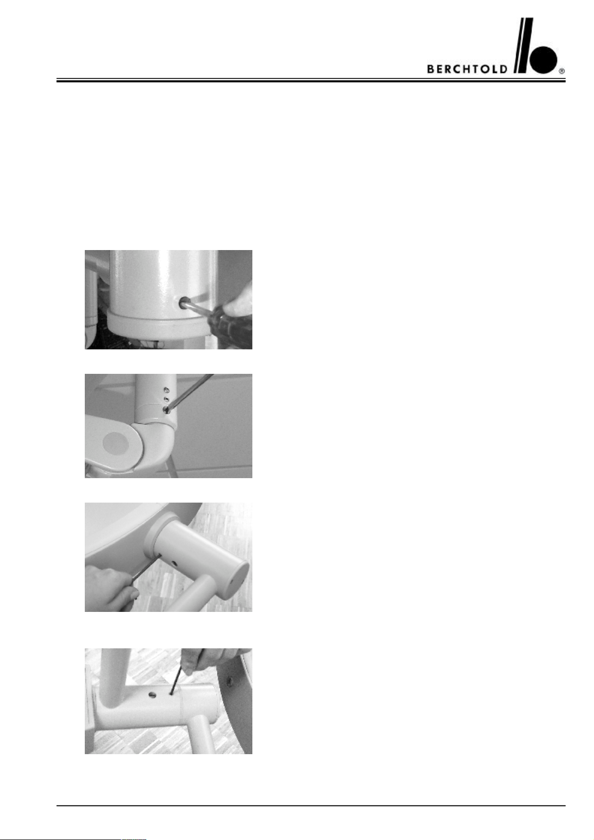
CHROMOPHARE® D 650plus, D 530plus, D 500plus, D 650, D 530, D 500 Service Manual (E)
12.BRAKE ADJUSTMENTS
Tools required:
Slotted screwdriver, large
Allen key 3 mm
Allen key 2,5 mm
The braking effect of the individual joints must be adjusted so
that the lamp housing remains in the required position. If a suspension arm of the OP light drifts away, the appropriate brake
screw must be tightened.
The mobility of the swivel arm can be adjusted with the brake
screw (slotted screw).
+ ð Clockwise
− ð Anti-clockwise
The mobility of the swivel arm can be adjusted with the brake
screw (slotted screw).
Cardan joint (classic cardanic)
+ ð Clockwise
− ð Anti-clockwise
The mobility of the light head can be adjusted with the brake
screw.
(Allen key 3 mm)
+ ð Clockwise
− ð Anti-clockwise
The mobility of the cardan joint can be adjusted with the brake
screw.
(Allen key 3 mm)
+ ð Clockwise
− ð Anti-clockwise
69
Page 70

CHROMOPHARE® D 650plus, D 530plus, D 500plus, D 650, D 530, D 500 Service Manual (E)
Cardan joint (flat cardanic)
The mobility of the cardan joint can be adjusted with the brake
screw.
(Allen key 2.5 mm)
+ ð Clockwise
− ð Anti-clockwise
Attention:
+ ð increase friction
− ð decrease friction
70
Page 71
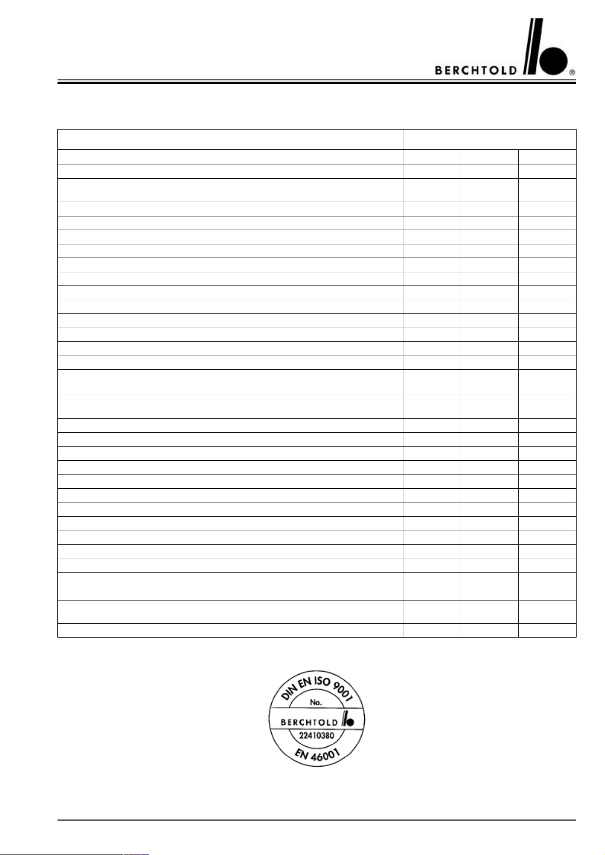
CHROMOPHARE® D 650plus, D 530plus, D 500plus, D 650, D 530, D 500 Service Manual (E)
13.MAINTENANCE PROGRAM
CHROMOPHARE® light .......................................................Serial no. ................................
i.O.*n.i.O.*Eliminated
Check lamp on/off switch.
Check maximum intensity of illumination at a distance of 1 m with small luminous
field.
Check maximum voltage of the bulb
Adjustment of luminosity i.e. degrees of luminosity
Lamp body: check that the hood support screws are properly tightened
Lamp body: check the condition of the cable comb
Commutation of the reserve bulbs
Focussing system
Check the Autobloc System / hand-rail tube (in the C 950/C952 models only)
Check the Autobloc System / hand-rail tube (in the C 950/C952 models only)
Diameter of the luminous body
System for following the luminous field
Brakes (clutch-type brakes)
Tension of the support arm springs
Support screws of the central positioning shaft / tighten the ceiling tube
(min 23 Nm)
Check the means of illumination i.e. the original BERCHTOLD halogen bulb
(Voltage, Watts)
Check the contacts of the bulb supports
Check the power feed cables of the bulb supports
Check the reflectors of the halogen bulbs
Check the glass filter shields
Check the collector ring and the strip contacts
Align the flanged tube
Eliminate or cover scratches and damage to the paintwork
Check the closing mechanism of the replacement holders
Rubber seals
Measure the resistance of the security conductor (compliance with VDE standards)
Check commutation to emergency current
In Chromo Vision lamps:
Check the CCD stop systems (only for the video camera with the 16-pole cable)
Check the 16-pole video camera cable with the specific equipment designed for this
purpose
Unify the colour definition schemes in the video camera and the monitor
Edition 10/98 (replaces all previous editions)
* i.O. = has been ordered n.i.O. = not ordered
BERCHTOLD GmbH & Co.
Medizin Elektronik
.........................................................................
Date / Signature (Installation technician)
Ludwigstaler Straße 25
Postfach 4052
D-78505 Tuttlingen
Tel. (+49) 7461 / 181-0
.........................................................................
Date / Signature (Collaborator – Hospital)
Fax (+49) 7461 / 181-200
Telex 762 532 berch d
71
Page 72
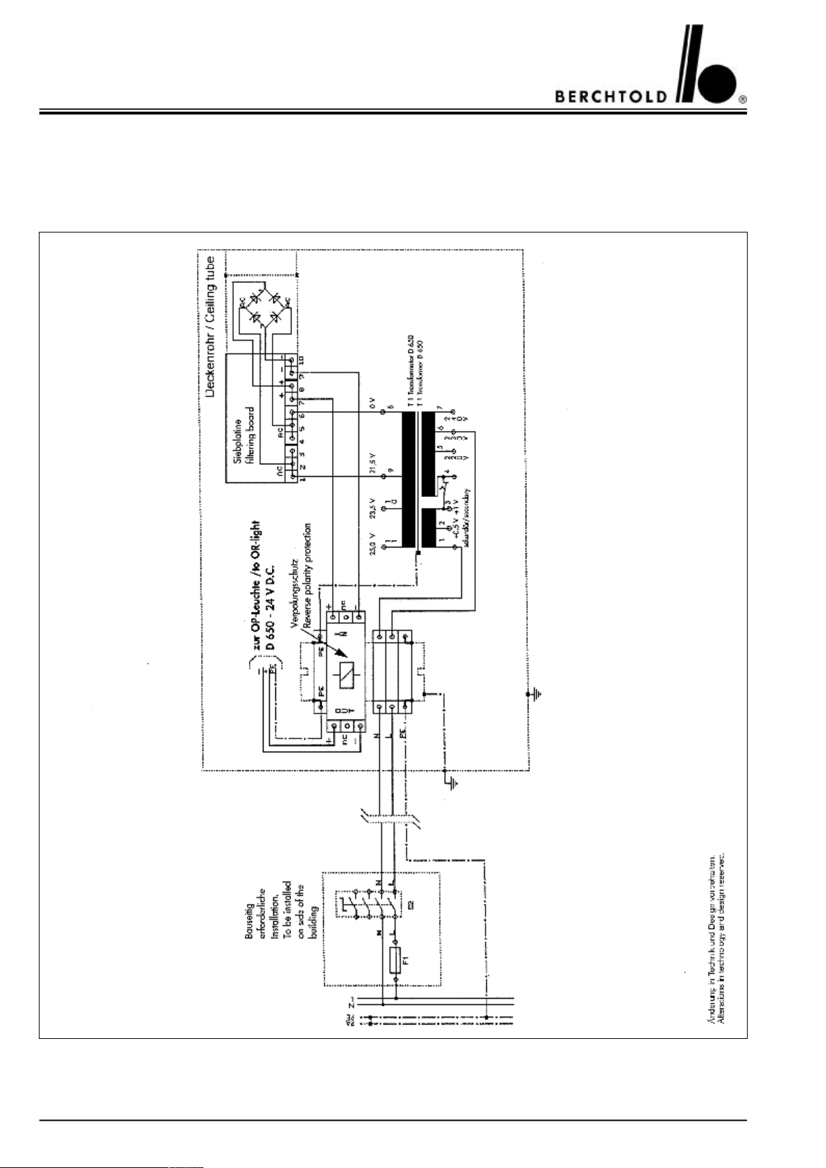
CHROMOPHARE® D 650plus, D 530plus, D 500plus, D 650, D 530, D 500 Service Manual (E)
14.WIRING DIAGRAMS
14.1CHROMOPHARE® D 650plus, D 650
Transformer mounted on the ceiling tube
72
Page 73
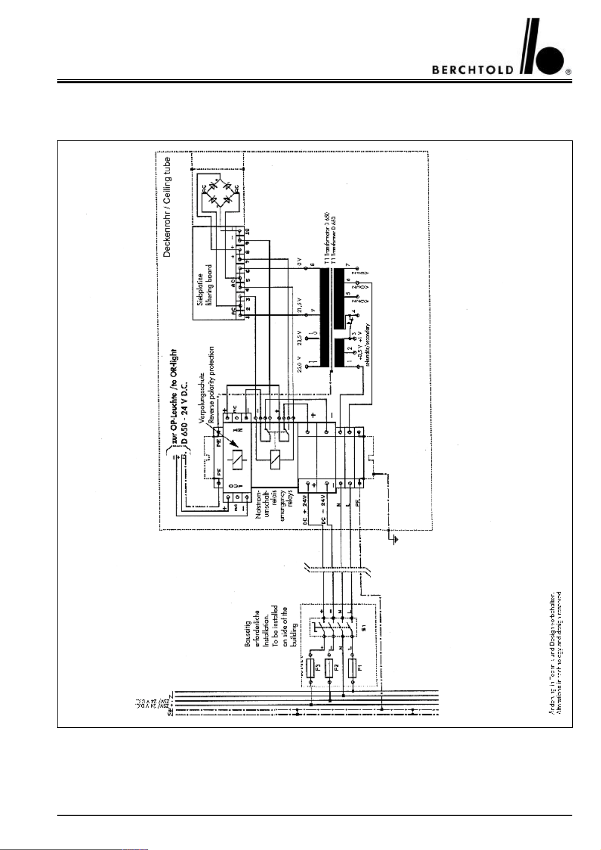
CHROMOPHARE® D 650plus, D 530plus, D 500plus, D 650, D 530, D 500 Service Manual (E)
14.2CHROMOPHARE® D 650plus, D 650
Transformer and emergency relays mounted on the ceiling tube
73
Page 74
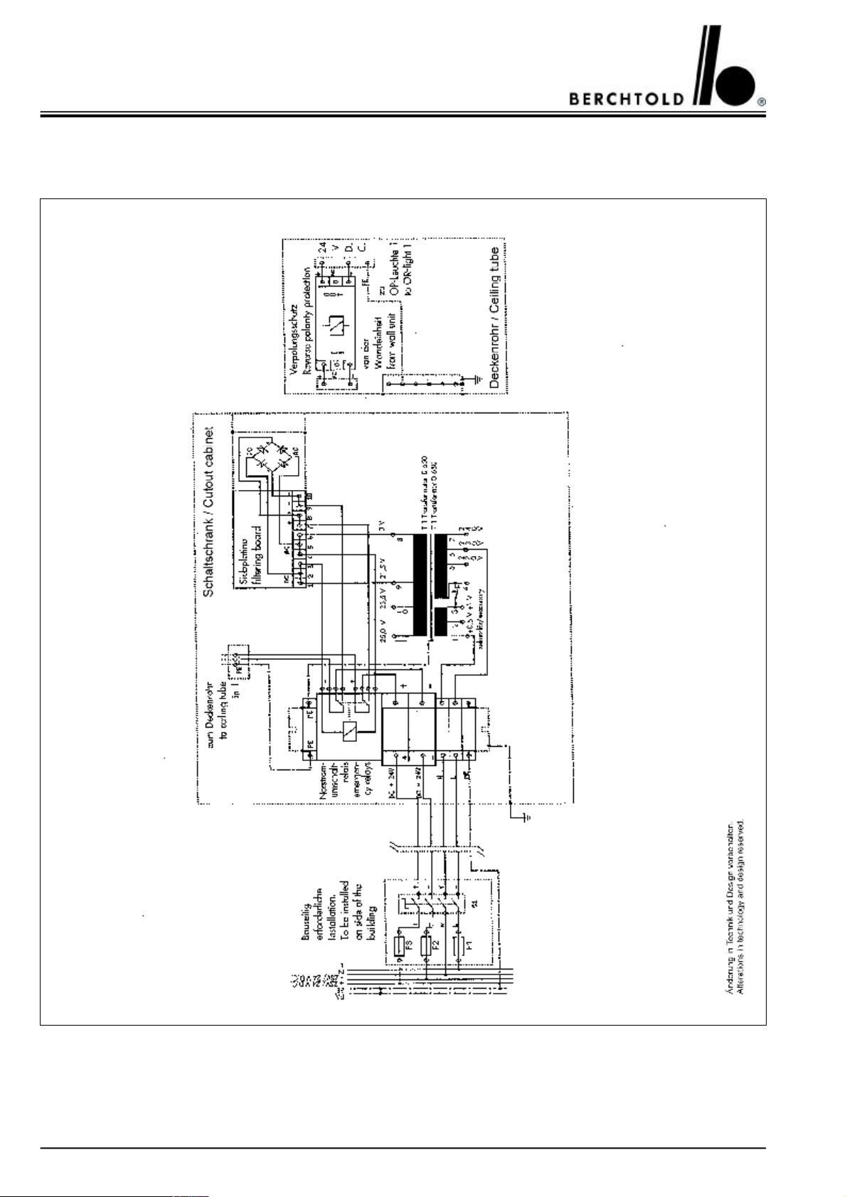
CHROMOPHARE® D 650plus, D 530plus, D 500plus, D 650, D 530, D 500 Service Manual (E)
14.3CHROMOPHARE® D 650plus, D 650
Power supply mounted in a cut-out cabinet
74
Page 75
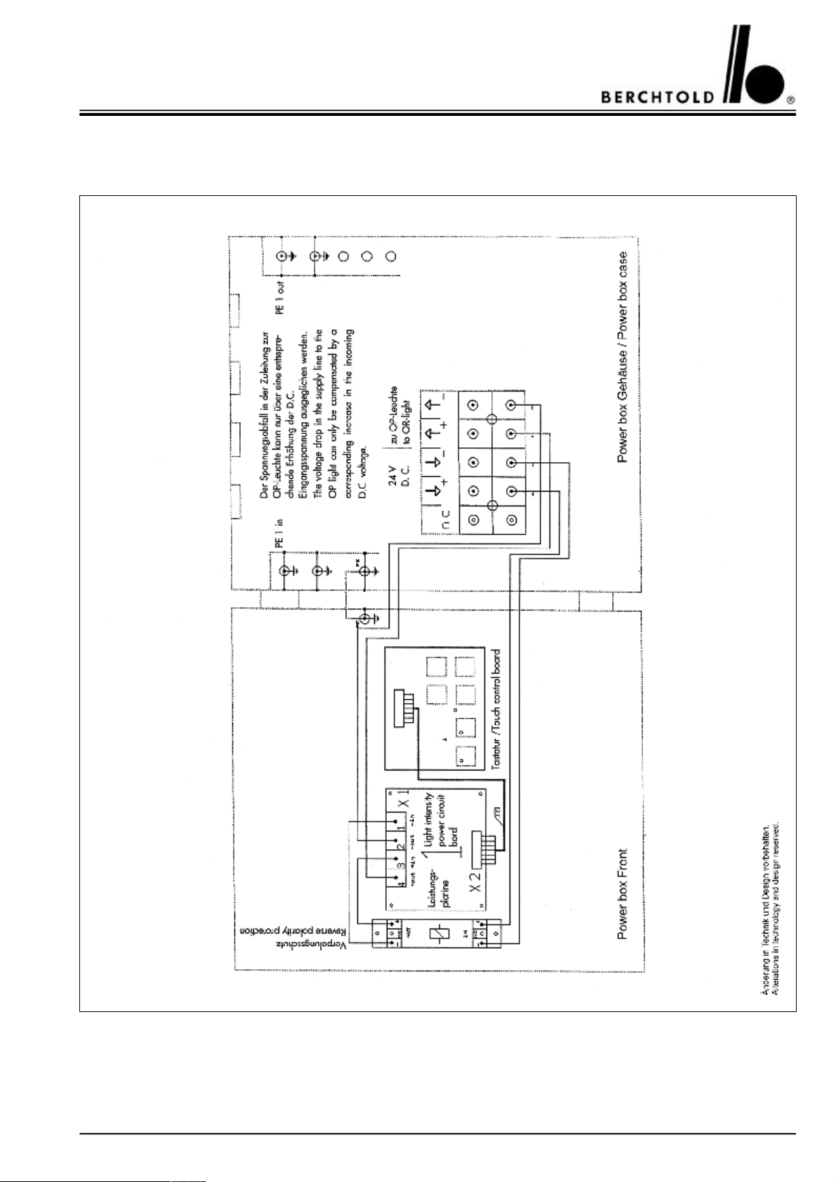
CHROMOPHARE® D 650plus, D 530plus, D 500plus, D 650, D 530, D 500 Service Manual (E)
14.4CHROMOPHARE® D 650plus, D 650
Control unit in “Power box” mounted separately from the OR-Light
75
Page 76
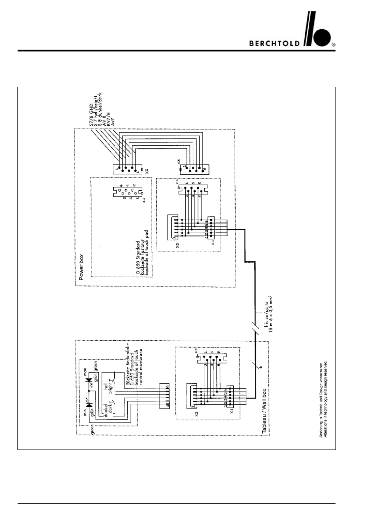
CHROMOPHARE® D 650plus, D 530plus, D 500plus, D 650, D 530, D 500 Service Manual (E)
14.5CHROMOPHARE® D 650plus, D 650
Touch panel for light intensity is mounted in the wall panel
76
Page 77
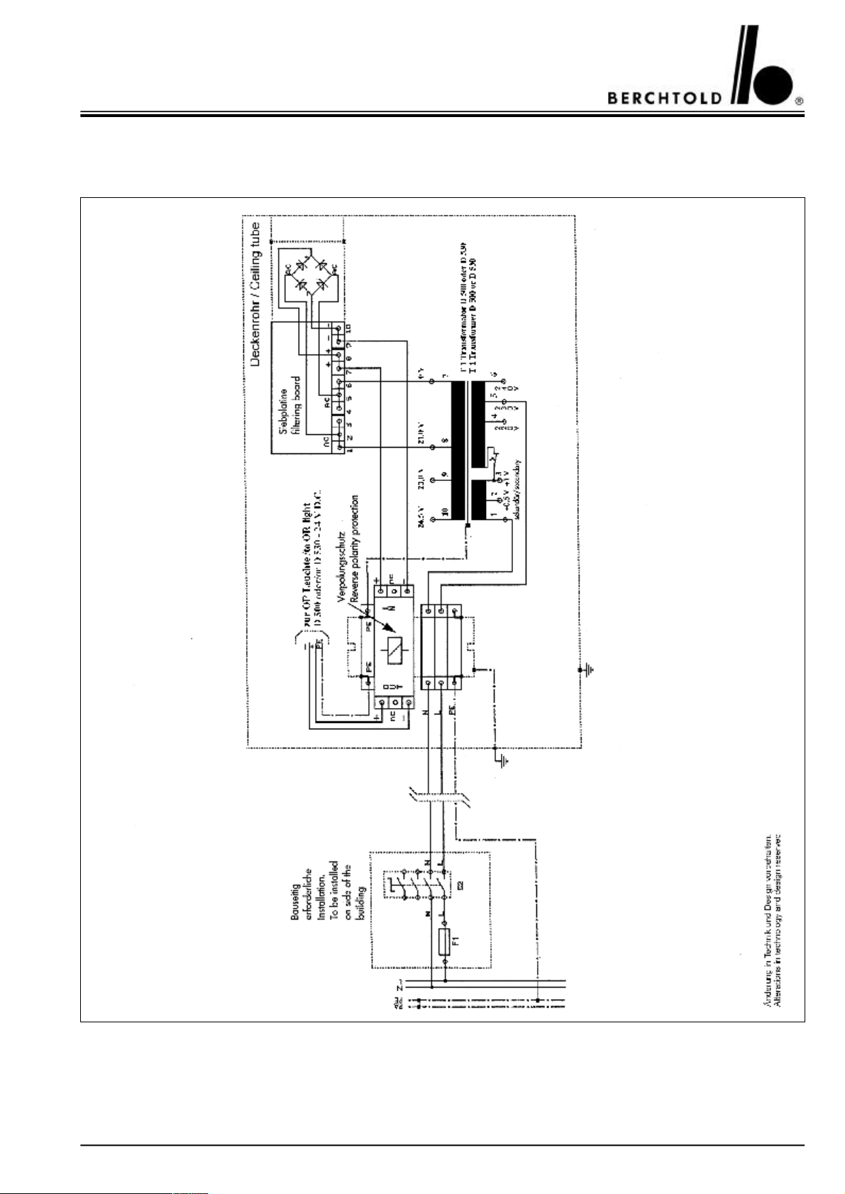
CHROMOPHARE® D 650plus, D 530plus, D 500plus, D 650, D 530, D 500 Service Manual (E)
14.6CHROMOPHARE® D 530plus, D 500plus, D 530, D 500
Transformer mounted on the ceiling tube
77
Page 78
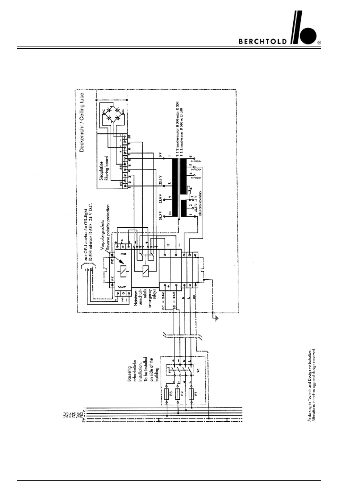
CHROMOPHARE® D 650plus, D 530plus, D 500plus, D 650, D 530, D 500 Service Manual (E)
14.7CHROMOPHARE® D 530plus, D 500plus, D 530, D 500
Transformer and emergency relays mounted on the ceiling tube
78
Page 79
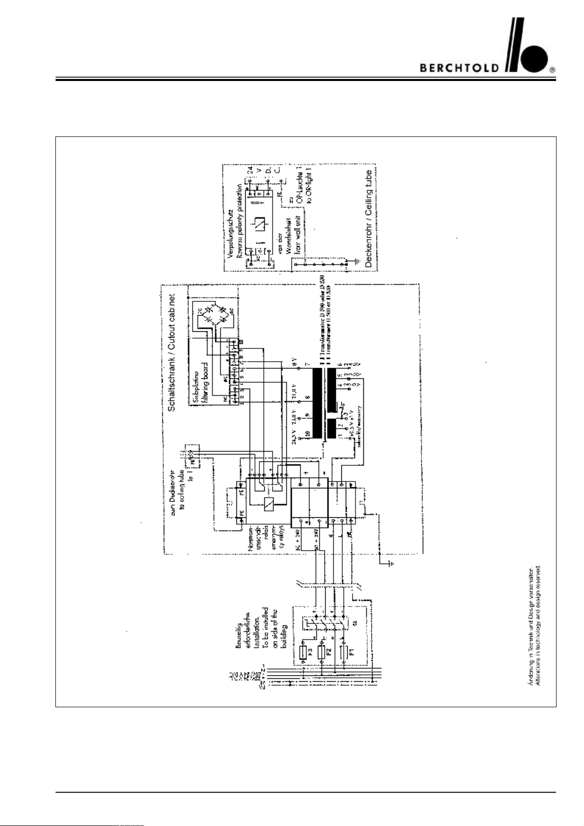
CHROMOPHARE® D 650plus, D 530plus, D 500plus, D 650, D 530, D 500 Service Manual (E)
14.8CHROMOPHARE® D 530plus, D 500plus, D 530, D 500
Power supply mounted in a cut-out cabinet
79
Page 80
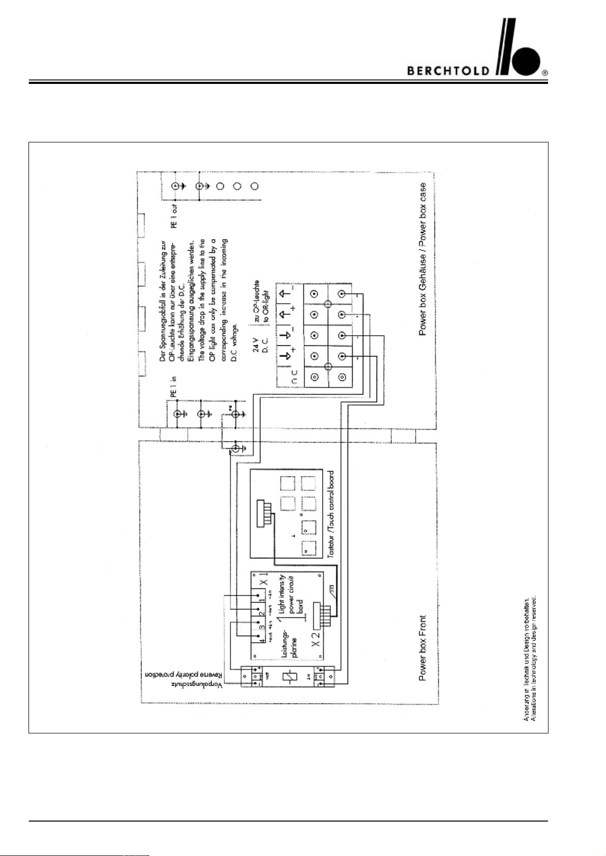
CHROMOPHARE® D 650plus, D 530plus, D 500plus, D 650, D 530, D 500 Service Manual (E)
14.9CHROMOPHARE® D 530plus, D 500plus, D 530, D 500
Control unit in “Power Box” mounted separately from the OR-Light
80
Page 81
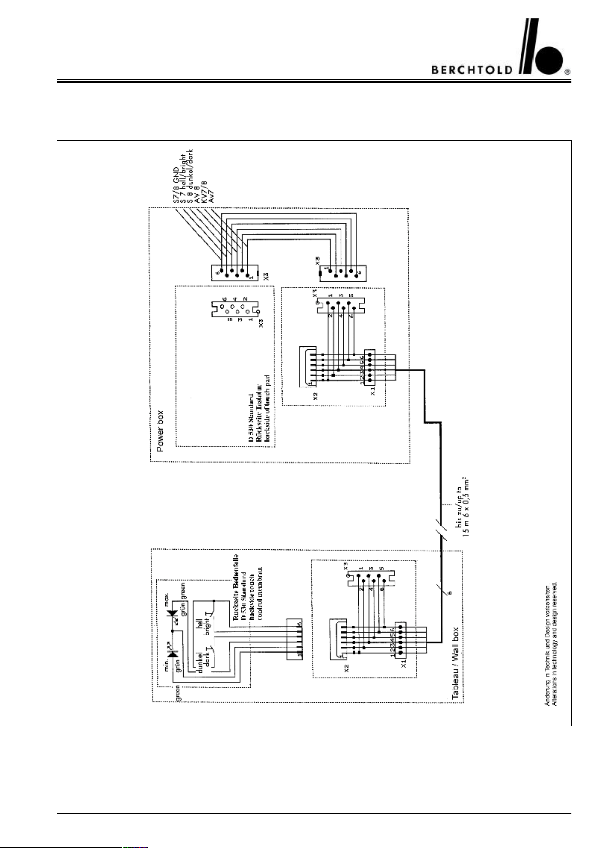
CHROMOPHARE® D 650plus, D 530plus, D 500plus, D 650, D 530, D 500 Service Manual (E)
14.10CHROMOPHARE® D 530plus, D 500plus, D 530, D 500
Touch panel for light intensity is mounted in the wall panel
81
Page 82
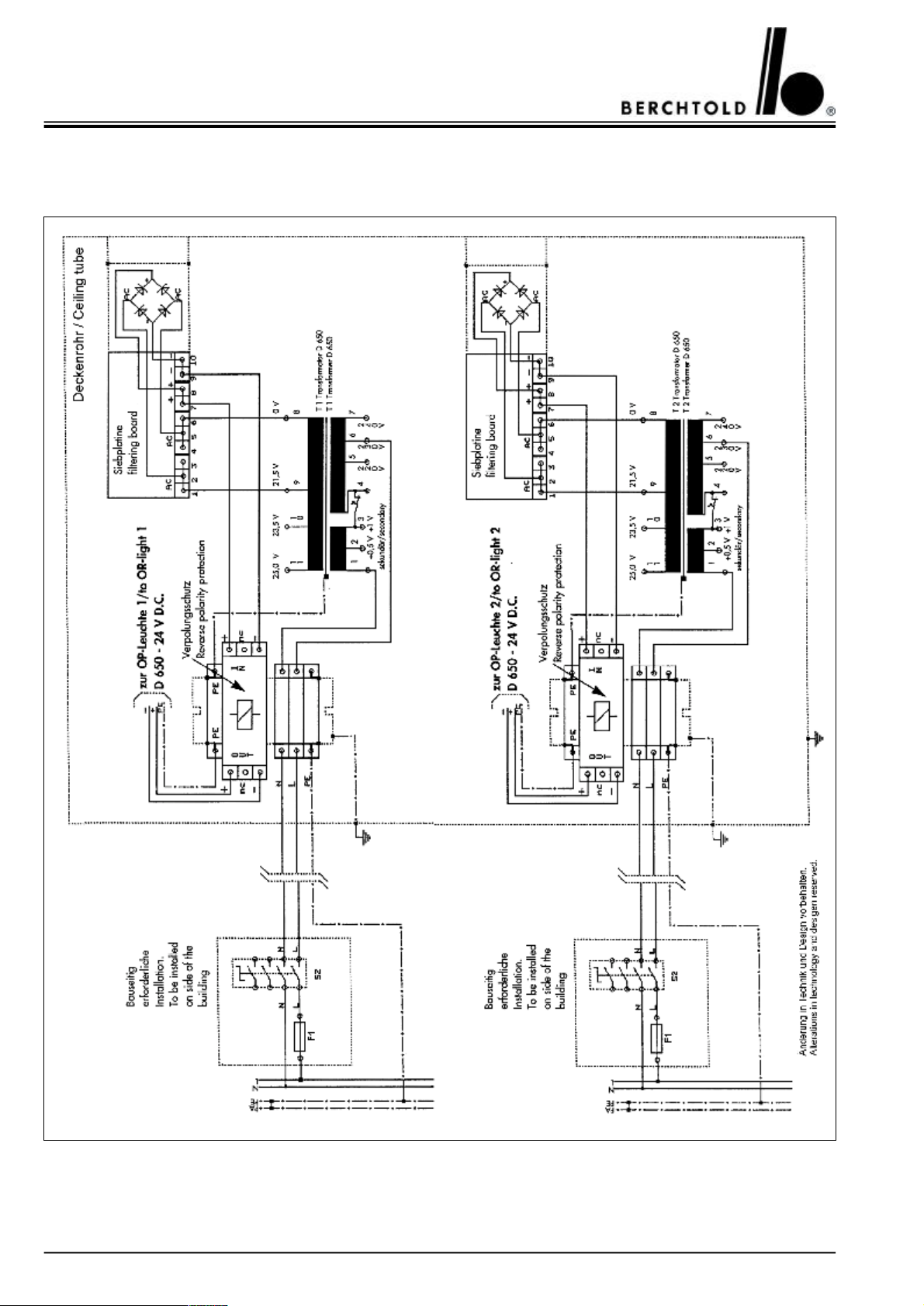
CHROMOPHARE® D 650plus, D 530plus, D 500plus, D 650, D 530, D 500 Service Manual (E)
14.11CHROMOPHARE® D 650plus/650plus, D 650/650
Transformers mounted on the ceiling tube
82
Page 83
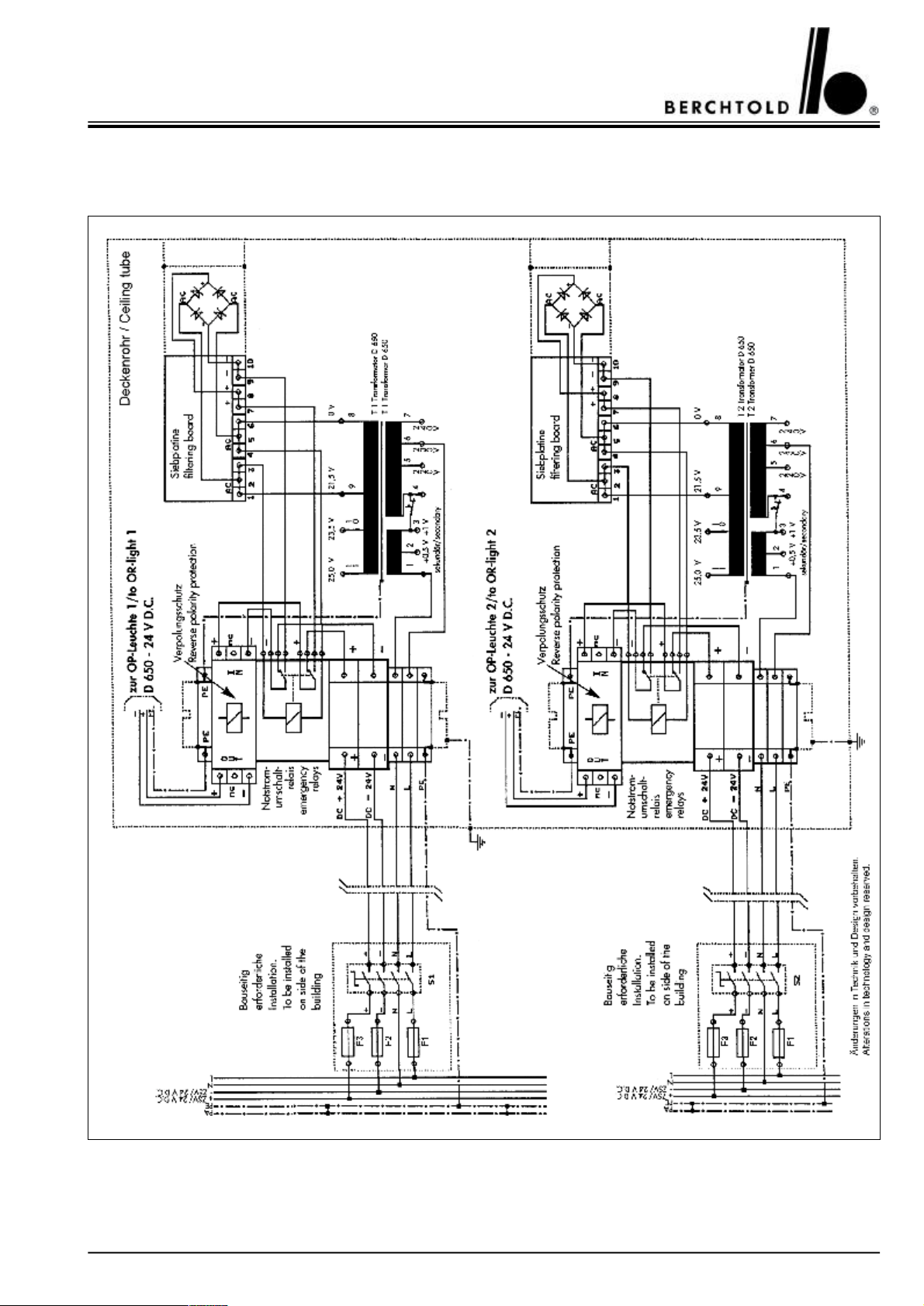
CHROMOPHARE® D 650plus, D 530plus, D 500plus, D 650, D 530, D 500 Service Manual (E)
14.12CHROMOPHARE® D 650plus/650plus, D 650/650
Transformers and emergency relays mounted on the ceiling tube
83
Page 84
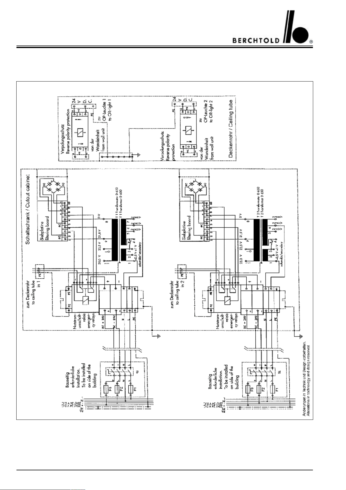
CHROMOPHARE® D 650plus, D 530plus, D 500plus, D 650, D 530, D 500 Service Manual (E)
14.13CHROMOPHARE® D 650plus/650plus, D 650/650
Power supply mounted in a cut-out cabinet
84
Page 85
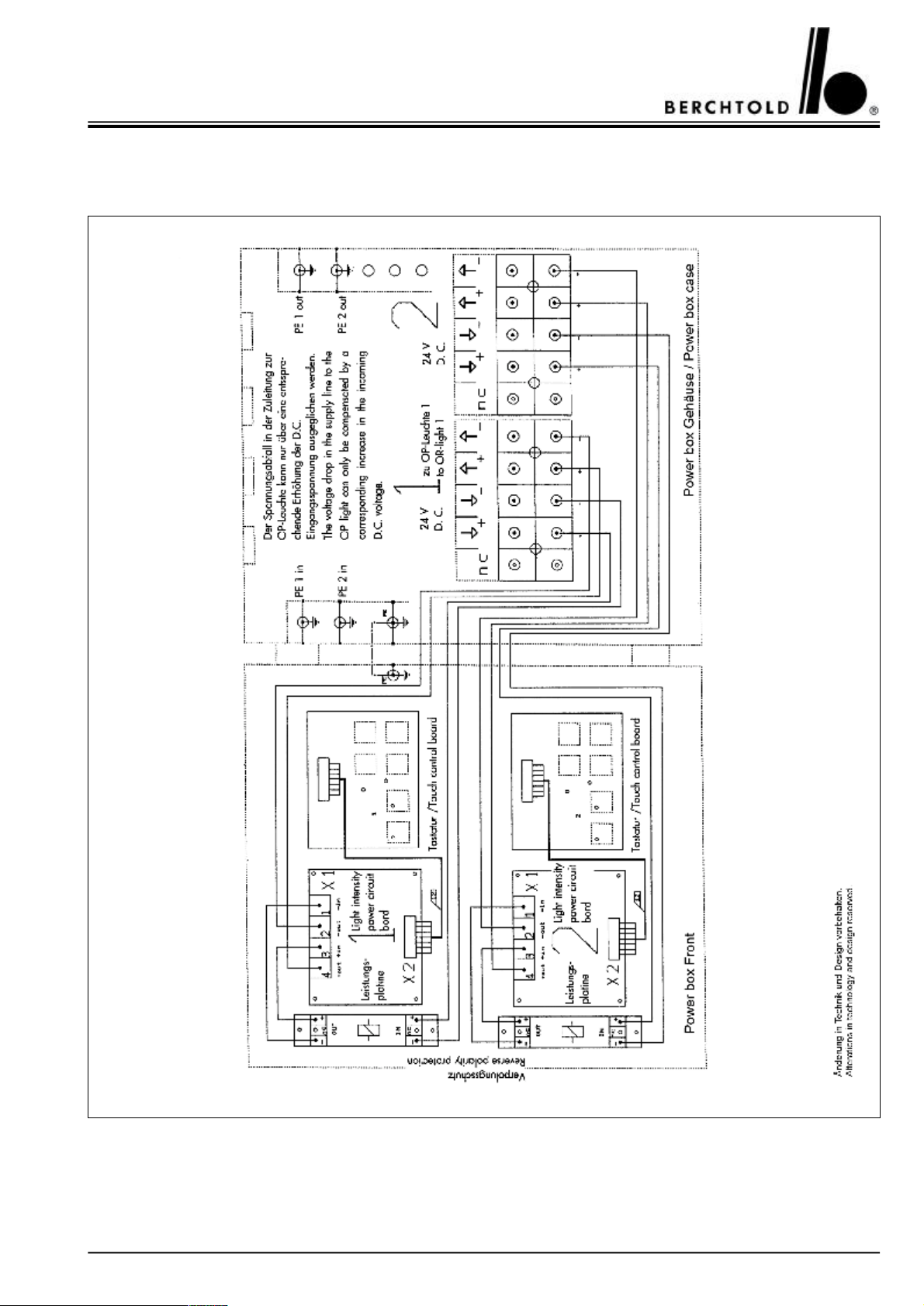
CHROMOPHARE® D 650plus, D 530plus, D 500plus, D 650, D 530, D 500 Service Manual (E)
14.14CHROMOPHARE® D 650plus/650plus, D 650/650
Control units in “Power Box” mounted separately from the OR-Light
85
Page 86
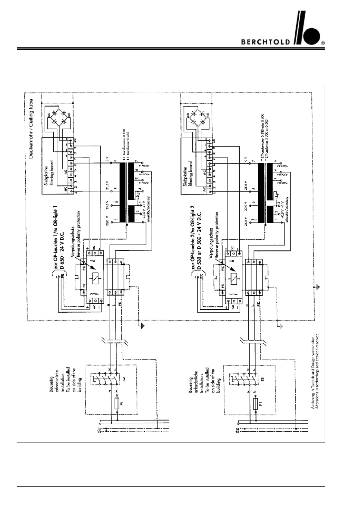
CHROMOPHARE® D 650plus, D 530plus, D 500plus, D 650, D 530, D 500 Service Manual (E)
14.15CHROMOPHARE® D 650plus/530plus, D 650plus/500plus, D 650/530, D 650/500
Transformers mounted on the ceiling tube
86
Page 87
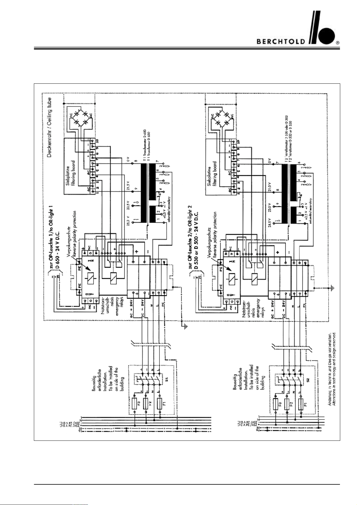
CHROMOPHARE® D 650plus, D 530plus, D 500plus, D 650, D 530, D 500 Service Manual (E)
14.16CHROMOPHARE® D 650plus/530plus, D 650plus/500plus, D 650/530, D 650/500
Transformers and emergency relays mounted on the ceiling tube
87
Page 88
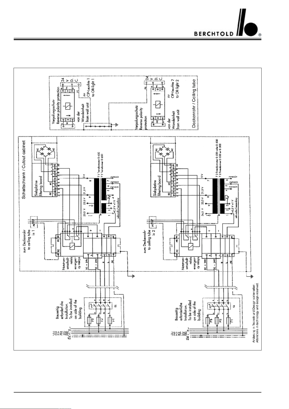
CHROMOPHARE® D 650plus, D 530plus, D 500plus, D 650, D 530, D 500 Service Manual (E)
14.17CHROMOPHARE® D 650plus/530plus, D 650plus/500plus, D 650/530, D 650/500
Power supply mounted in a cut-out cabinet
88
Page 89
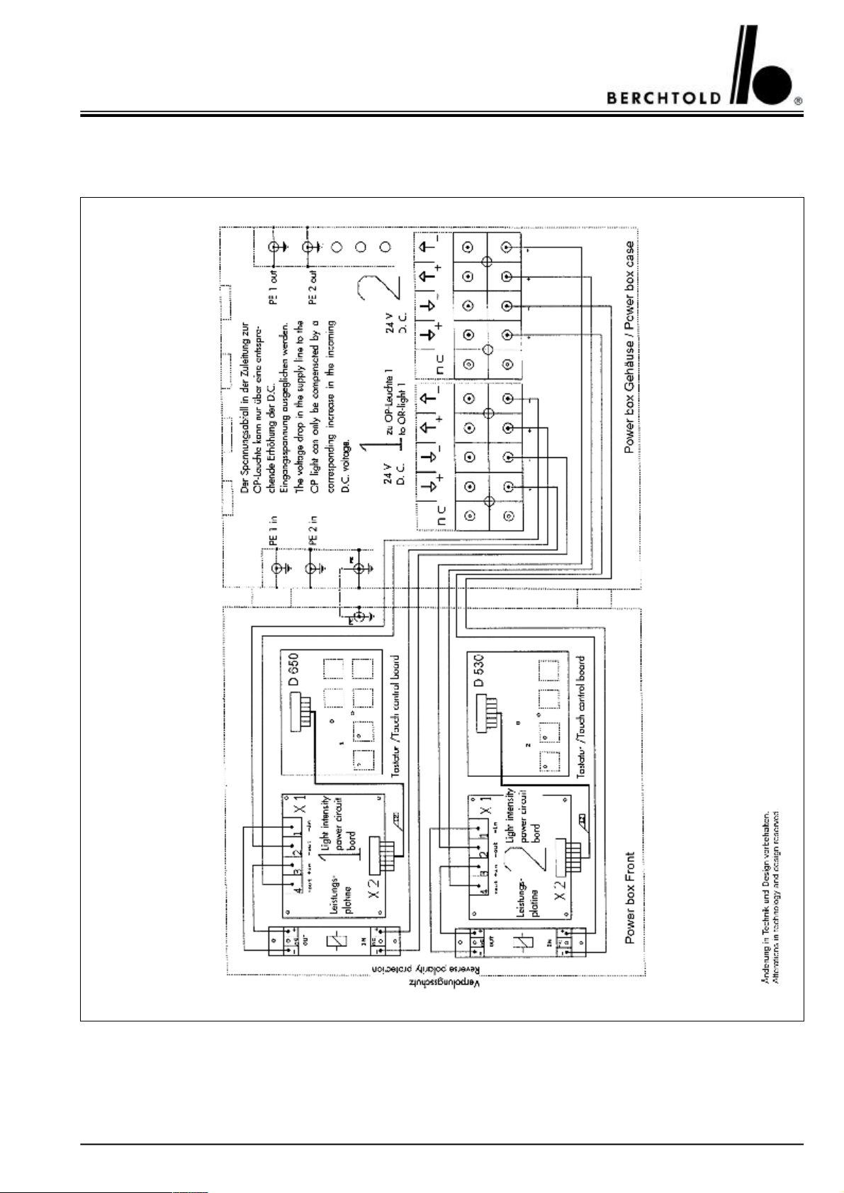
CHROMOPHARE® D 650plus, D 530plus, D 500plus, D 650, D 530, D 500 Service Manual (E)
14.18CHROMOPHARE® D 650plus/530plus, D 650/530
Control units in “Power Box” mounted separately from the OR-Light
89
Page 90
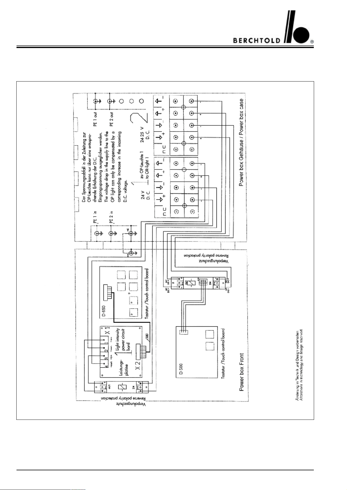
CHROMOPHARE® D 650plus, D 530plus, D 500plus, D 650, D 530, D 500 Service Manual (E)
14.19CHROMOPHARE® D 650plus/500plus, D 650/500
Control units in “Power Box” mounted separately from the OR-Light
90
Page 91
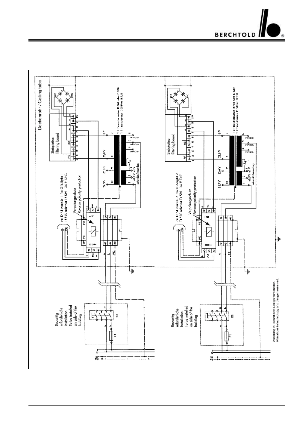
CHROMOPHARE® D 650plus, D 530plus, D 500plus, D 650, D 530, D 500 Service Manual (E)
14.20CHROMOPHARE® D 530plus/530plus, D 500plus/500plus, D 530/530, D 500/500
Transformers mounted on the ceiling tube
91
Page 92
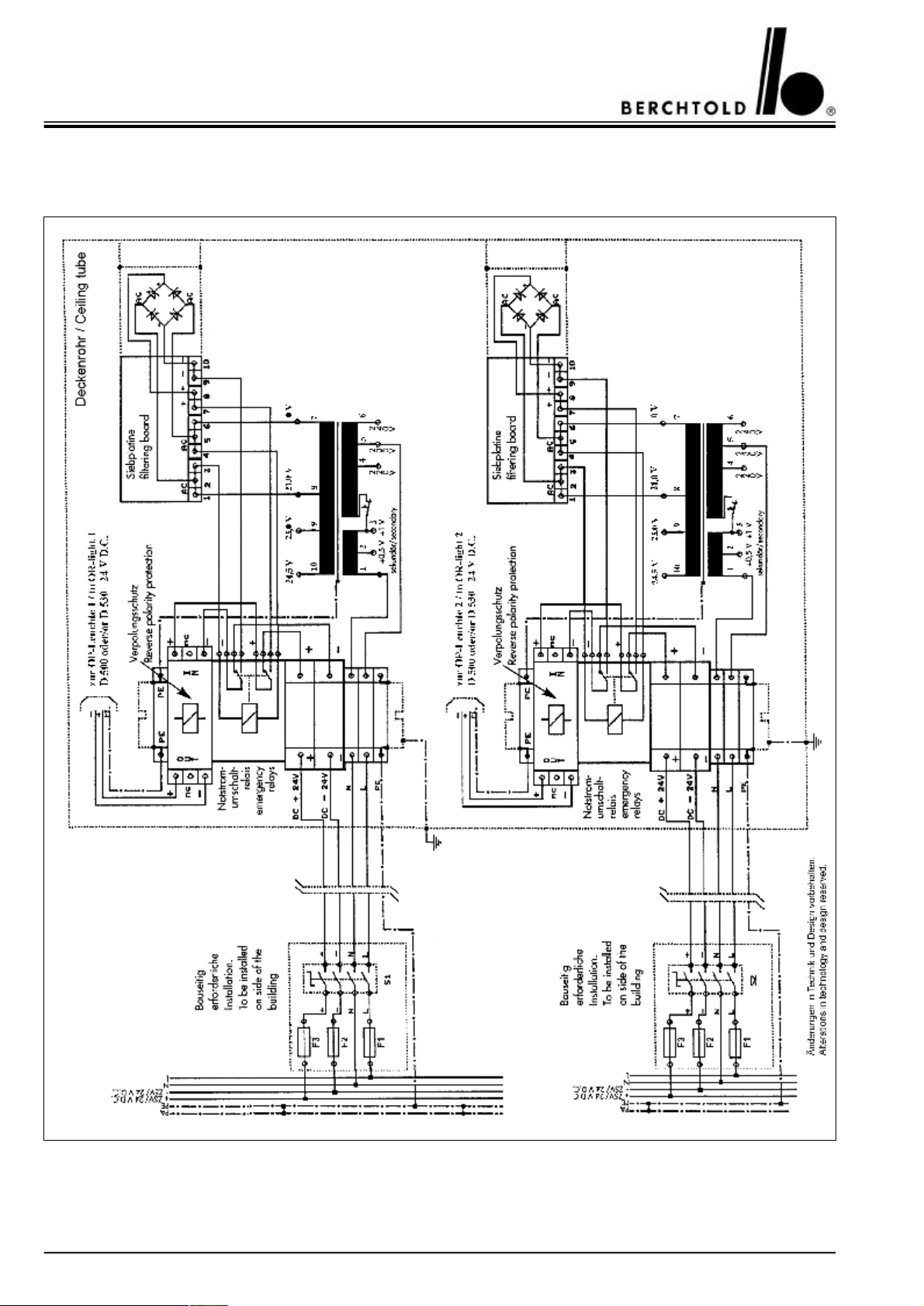
CHROMOPHARE® D 650plus, D 530plus, D 500plus, D 650, D 530, D 500 Service Manual (E)
14.21CHROMOPHARE® D 530plus/530plus, D 500plus/500plus, D 530/530, D 500/500
Transformers and emergency relays mounted on the ceiling tube
92
Page 93
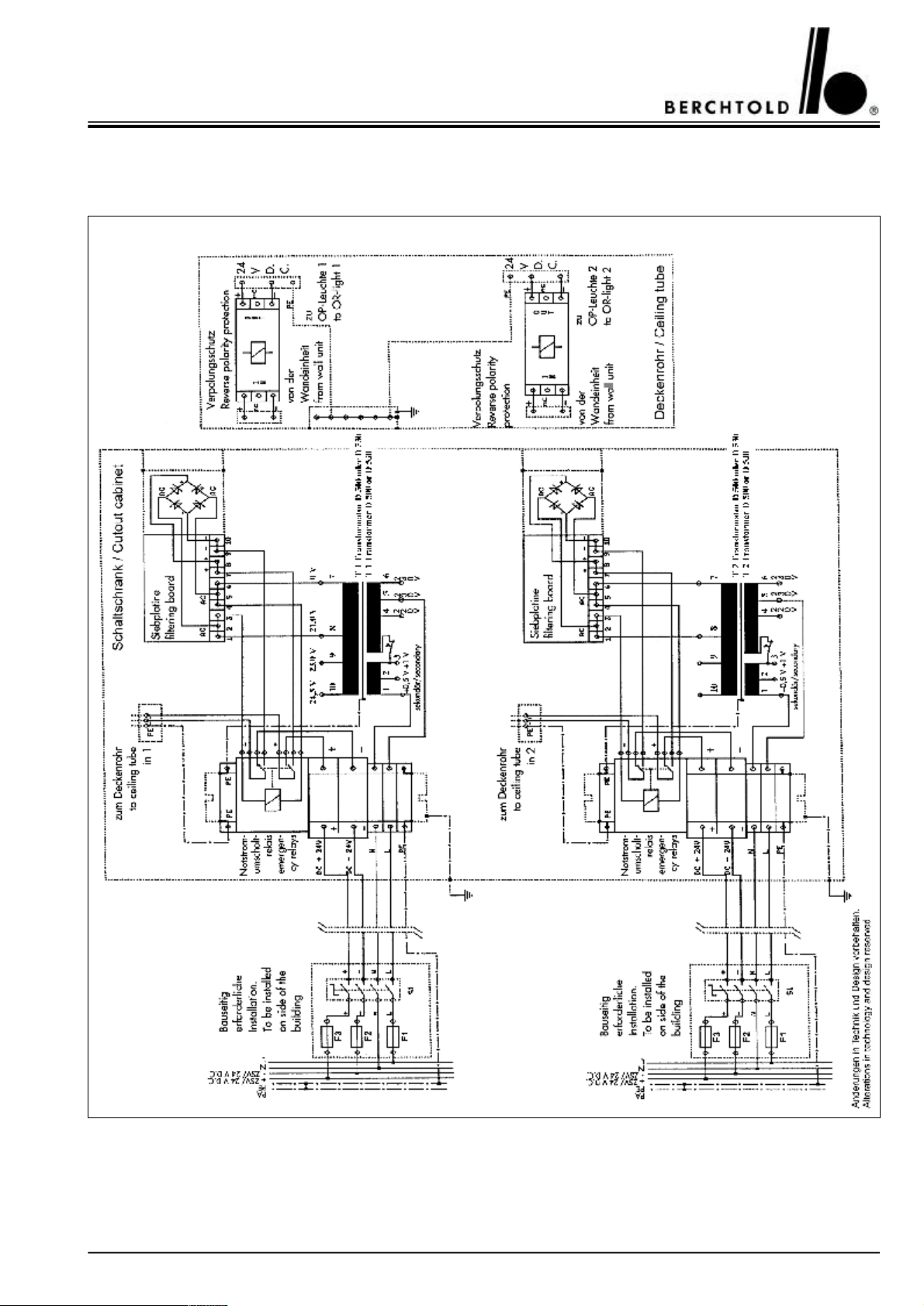
CHROMOPHARE® D 650plus, D 530plus, D 500plus, D 650, D 530, D 500 Service Manual (E)
14.22CHROMOPHARE® D 530plus/530plus, D 500plus/500plus, D 530/530, D 500/500
Power supply mounted in a cut-out cabinet
93
Page 94
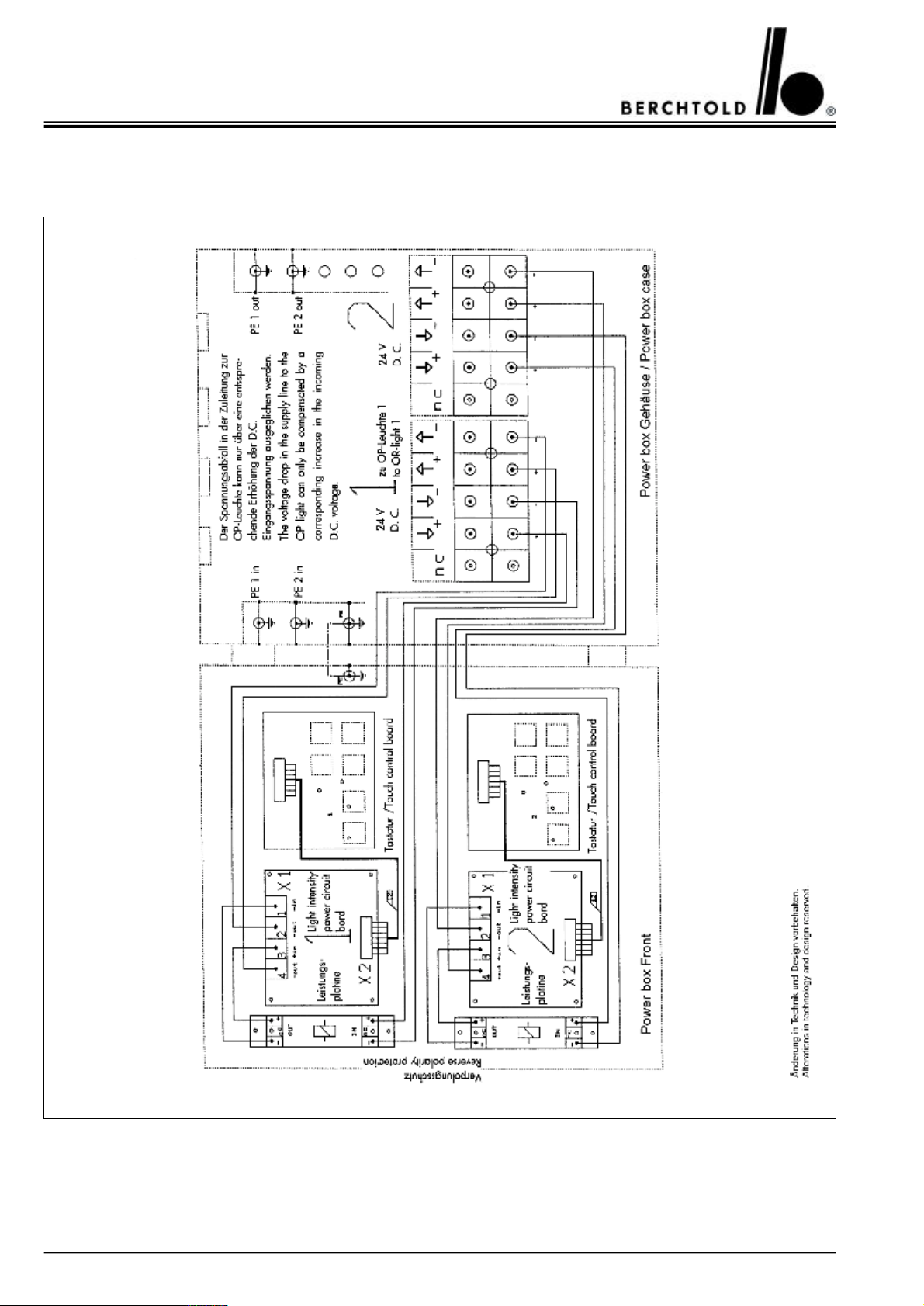
CHROMOPHARE® D 650plus, D 530plus, D 500plus, D 650, D 530, D 500 Service Manual (E)
14.23CHROMOPHARE® D 530plus/530plus, D 530/530
Control units in “Power Box” mounted separately from the OR-Light
94
Page 95
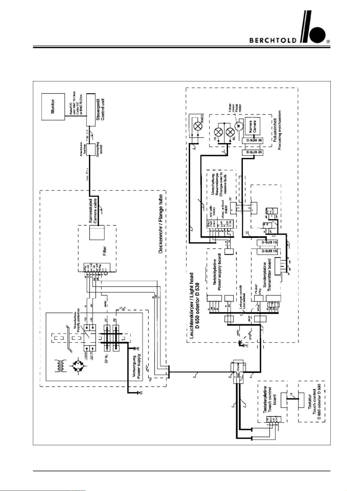
CHROMOPHARE® D 650plus, D 530plus, D 500plus, D 650, D 530, D 500 Service Manual (E)
14.24CHROMOPHARE® D 650plus, D 530plus, D 650, D 530
Wiring diagram for OR-lights with BERCHTOLD camera ChromoVision® AF II
95
Page 96
CHROMOPHARE® D 650plus, D 530plus, D 500plus, D 650, D 530, D 500 Service Manual (E)
15.POWER REQUIREMENTS
15.1 List of fuse specifications
Fuse values to be installed on-site [A]
220 – 240 V110 – 120 V
LightL
F1
[A]
D 500plus
D 530plus
D 650plus4166,316
D 500
D 530
D 6504166,316
All fuse slow blow
15.2 List of terminal voltages
The terminal voltages specified in table below must be provided on the flanged tube of the CHROMOPHARE®
light or the Power Box
LightA.C.
210410
210410
Ceiling tubePower Box
[V]
Battery
F2/F3
[A]
D.C.
[V]
L
F1
[A]
A.C.
[V]
Battery
F2/F3
[A]
D.C.
[V]
D 500plus
D 530plus
D 650plus21,5 (*24 + 1,5/-0,321,5 (*24 + 1,5/-0,3
D 500
D 530
D 65021,5 (*24 + 1,5/-0,321,5 (*24 + 1,5/-0,3
(* filtering board next in line
21,5 (*24 + 1,5/-0,321,5 (*24 + 1,5/-0,3
21,5 (*24 + 1,5/-0,321,5 (*24 + 1,5/-0,3
96
Page 97

CHROMOPHARE® D 650plus, D 530plus, D 500plus, D 650, D 530, D 500 Service Manual (E)
97
Page 98

CHROMOPHARE® D 650plus, D 530plus, D 500plus, D 650, D 530, D 500 Service Manual (E)
BERCHTOLD GmbH & Co. KG
Ludwigstaler Straße 25
Tel. (+49) 7461 / 181-0
Fax (+49) 7461 / 181-200
Postfach 4052
56 791/M-S/B/03.2003 © BERCHTOLD GmbH & Co.KG
Reproduction including excerpts, prohibited.
Alterations in technology and design reserved.
D-78505 Tuttlingen
Internet: http://www.Berchtold.de
e-mail: [email protected]
Service department:
Tel. (+49) 7461 / 181-217
Fax (+49) 7461 / 181-311
98
 Loading...