

Page 1
Chromalox
© 1999 Wiegand Industrial Division, Emerson Electric Co.
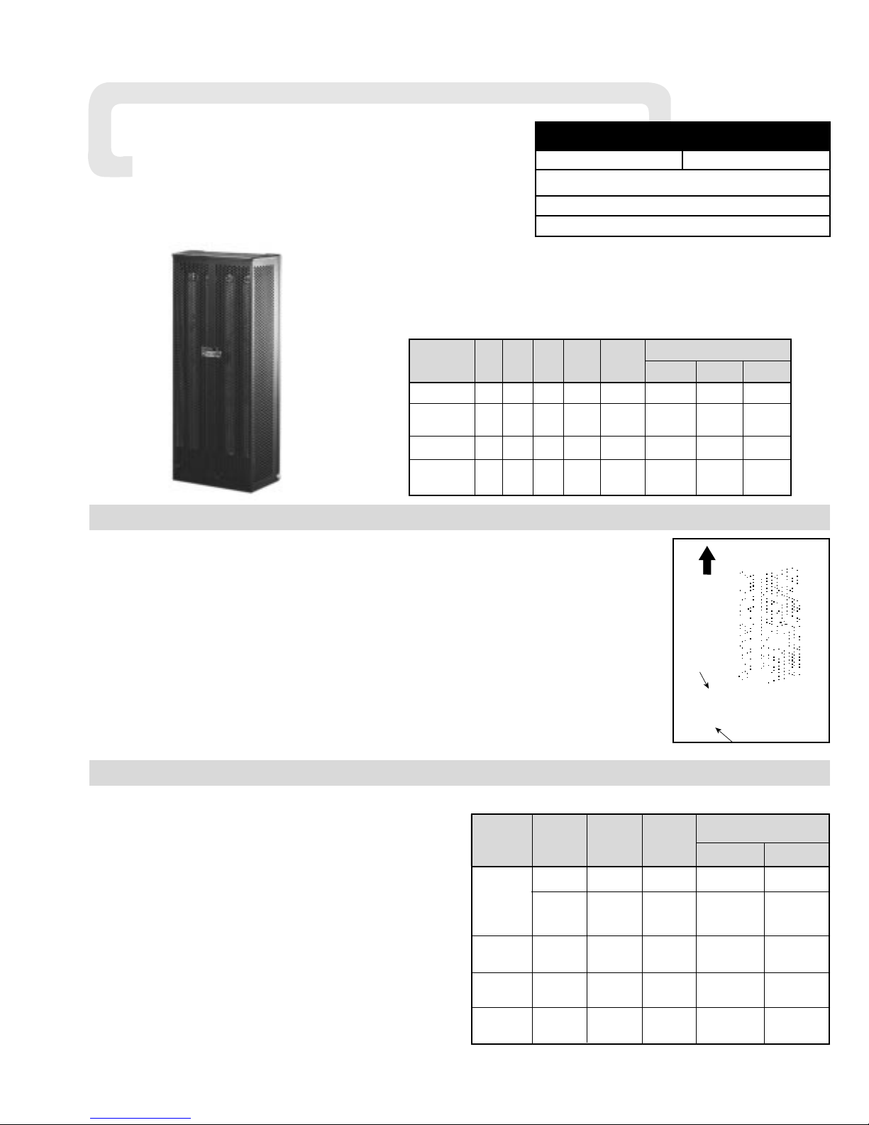
Type V Industrial Wall Mounted
Convection Space Heater
1. All wiring should be done in accordance with local codes and the
National Electrical Code by a qualified person as defined in the NEC.
2. Connect air heaters to same line voltage as on heater nameplate.
3 . Check possibility of corrosion if heaters are operated in atmospheres
other than air.
4. In general, locate heater approximately 1 foot from the floor, but not
less than 6 inches, for best overall results. Heater, however can be
located anywhere to meet unique requirements of any particular
application.
5. Heaters are mounted directly on any type of surface-masonry, con-
crete, block, plastered walls, metal framework, etc.-using appropriate
hardware.
6. Standard heaters are mounted in a vertical position with the terminal
end on the bottom. This unit has special baffle plates and vent holes
in the cover to ensure sufficient convection currents. Make sure that
the heater is mounted so that the
mounting label located on the back
panel points up as shown in Figure
1 . The end covers will be at the top
and bottom of the heater with the
terminal access at the bottom end.
WARNING: Never recess
heater into wall.
Not Suitable for household or residential use.
Do not cover.
Keep combustible materials away
from heater.
Specifications —
Dimensions (In.)
No.
Model kW Volts Elem. Amps Btuh Height Width Depth
V-2020 2 240 4 8.3 6,824 27 12-3/4 5-3/4
V-2030 3 240 4 12.5 10,236 27 12-3/4 5-3/4
V-2030 3 480 4 6.3 10,236 27 12-3/4 5-3/4
V-2040 4.5 120 6 25 10,236 27 17-3/4 5-3/4
V-2040 4.5 240 6 18.8 15,354 27 17-3/4 5-3/4
V-2040 4.5 480 6 9.4 15,354 27 17-3/4 5-3/4
GENERAL
WARNING: Hazard of Shock. Disconnect all power
before installing heater.
1. Locate heater position on wall.
2. To locate mounting holes, see Specifications Table for heater
in question. In standard 16” stud center frame construction,
locate wall studding and locate 1 upper and 1 lower mounting
hole in center of stud.
3. Drill a pilot hole in metal or wood surfaces using a convenient
small size drill.
4. Drill the 4 holes in accordance with sizes in Table 1. Insert
anchors where applicable.
5. Remove cover screws.
6. Remove cover.
7. Fasten to wall with screws as listed in Table 1. Turn tight then
back off 1/2 turn, to allow for expansion and contraction.
8. Replace heater cover-fasten with screws and washers removed
in Step 5.
Screw Size to Fit Hole Size
In Heater Mounting Plates
**
Type Mounting Accessory Screw Drill Size
Surface Hardware Type and Type Terminal End Opposite End
Ackerman
Rd. Hd.
1/2” Masonry 1/4 x 20 x 3” 1/4 x 20 x 2”
Mach. Steel
Concrete, Block Rd. Hd Mach.
Masonry
Lead Anchor
Steel or Pan
3/8” Masonry #14 x 3” #14 x 2”
Hd. Metal
(Self-Tapping)
Wood or
Wood Studs — Metal — #14 x 3” #14 x 2”
(Self-Tapping)
Plaster Wall
Toggle
Hollow or —
Bolt
#7 1/4 x 4” 1/4 x 3”
Similar Type
*Metal Beam,
Rd. Hd.
Nuts, Washers Mach. #7 Twist 1/4 x 20 x 1-11/16” 1/4 x 20 x 13/16”
Channel, etc.
Steel
Table 1 — Suggested Heater Mounting Screws (Types and Sizes)
Figure 1 — Mounting
* If clearance permits, use lockwasher and nut; otherwise, drill and tap. To these lengths add thickness
of beam, washers, nut etc.
** If mounting structure permits, except plastered hollow walls, explosive type anchors can be used.
Suggest sizes noted in Table and/or sketches to be used to determine size of anchors.
MOUNTING
®
Installation
and
REWNEWAL PARTS IDENTIFICATION
SERVICE REFERENCE
DIVISION 4 SECTION V
SALES
REFERENCE
DATE
(Supersedes PF404-3)
MAY, 1999
PF404-4
161-048364-001
Install
With This
End Up
6" Min.
Mounting
Floor
Page 2
Chromalox warrants only that the Products and parts manufactured by Chromalox, when shipped, and the work performed by Chromalox when performed, will meet all applicable specification and other specific product and work requirements (including those of performance), if any, and will be free from defects in material and workmanship under normal
conditions of use. All claims for defective or nonconforming (both hereinafter called defective) Products, parts or work
under this warranty must be made in writing immediately upon discovery, and in any event, within one (1) year from delivery, provided, however all claims for defective Products and parts must be made in writing no later than eighteen (18)
months after shipment by Chromalox. Defective and nonconforming items must be held for Chromalox's inspections and
returned to the original f.o.b. point upon request. THE FOREGOING IS EXPRESSLY IN LIEU OF ALL OTHER WARRANTIES
WHATSOEVER, EXPRESS, IMPLIED AND STATUTORY, INCLUDING, WITHOUT LIMITATION, THE IMPLIED WARRANTIES OF MERCHANTABILITY AND FITNESS FOR A PARTICULAR PURPOSE.
Notwithstanding the provisions of this WARRANTY AND LIMITATION Clause, it is specifically understood that Products
and parts not manufactured and work not performed by Chromalox are warranted only to the extent and in the manner
that the same are warranted to Chromalox by Chromalox's vendors, and then only to the extent that Chromalox is reasonably able to enforce such warranty, it being understood Chromalox shall have no obligation to initiate litigation unless
Buyer undertakes to pay all cost and expenses therefor, including but not limited to attorney's fees, and indemnifies
Chromalox against any liability to Chromalox's vendors arising out of such litigation.
Upon Buyer's submission of a claim as provided above and its substantiation, Chromalox shall at its option either (i)
repair or replace its Products, parts or work at the original f.o.b. point of delivery or (ii) refund an equitable portion of the
purchase price.
THE FOREGOING IS CHROMALOX'S ONLY OBLIGATION AND BUYER'S EXCLUSIVE REMEDY FOR BREACH OF WARRANTY, AND IS BUYER'S EXCLUSIVE REMEDY AGAINST CHROMALOX FOR ALL CLAIMS ARISING HEREUNDER OR
RELATING HERETO WHETHER SUCH CLAIMS ARE BASED ON BREACH OF CONTRACT, TORT (INCLUDING NEGLIGENCE AND STRICT LIABILITY) OR OTHER THEORIES, BUYER'S FAILURE TO SUBMIT A CLAIM AS PROVIDED ABOVE
SHALL SPECIFICALLY WAIVE ALL CLAIMS FOR DAMAGES OR OTHER RELIEF, INCLUDING BUT NOT LIMITED TO
CLAIMS BASED ON LATENT DEFECTS. IN NO EVENT SHALL BUYER BE ENTITLED TO INCIDENTAL OR CONSEQUENTIAL DAMAGES AND BUYER SHALL HOLD CHROMALOX HARMLESS THEREFROM. ANY ACTION BY BUYER ARISING
HEREUNDER OR RELATING HERETO, WHETHER BASED ON BREACH OF CONTRACT, TORT (INCLUDING NEGLIGENCE
AND STRICT LIABILITY) OR OTHER THEORIES, MUST BE COMMENCED WITHIN ONE (1) YEAR AFTER THE DATE OF
SHIPMENT OR IT SHALL BE BARRED.
W2008M
WARRANTY AND LIMITATION OF REMEDY AND LIABILITY
Chromalox
P R O D U C T S E R V I C E
2150 N. RULON WHITE BLVD., OGDEN, UT 84404
Phone: 1-800-368-2493
99 - 039
TA - S9 - EF
Litho in U.S.A.
MOUNTING
WIRING
OPERATION
RENEWAL PARTS IDENTIFICATION
WARNING: Hazard of Shock. Any installation involving
electric heaters must be effectively grounded in accordance with the National Electrical Code to eliminate
shock hazard.
Note: All wiring should be done in accordance with local codes and the
National Electrical Code by a qualified person as defined in the NEC.
1. Electrical wiring enters heater case through 7/8” opening in end of
heater.
2. Grounding conductor, with green insulation, should be secured to
grounding screw located on case.
Dimensions (In.)
Model Height Width Depth
V-2020 27 12-3/4 5-3/4
V-2030 27 12-3/4 5-3/4
V-2040 27 17-3/4 5-3/4
Heater Mounting —
WARNING: Hazard of fire or discoloration of temperature
sensitive fabrics. Keep combustible materials and such
fabrics at least 4” away from front of cover or above cover.
DANGER:Hazard of Fire. This heater is not intended for
use in hazardous atmospheres where flammable vapors,
gases, liquids or other combustible atmospheres are present as defined in the National Electrical Code. Failure to
comply can result in explosion or fire.
MAINTENANCE
1. WARNING: Hazard of Shock. Disconnect all power
before attempting to service this heater.
2. Following long periods of idleness, heater should be vacuumed
before start-up to remove accumulated combustible particles which
will incinerate causing smoking and consequent wall discoloration.
3. If heater is located in areas of heavy traffic, furnish suitable heater
guard (wall mounted pipe rail in front of case, for example) to prevent damage to heater.
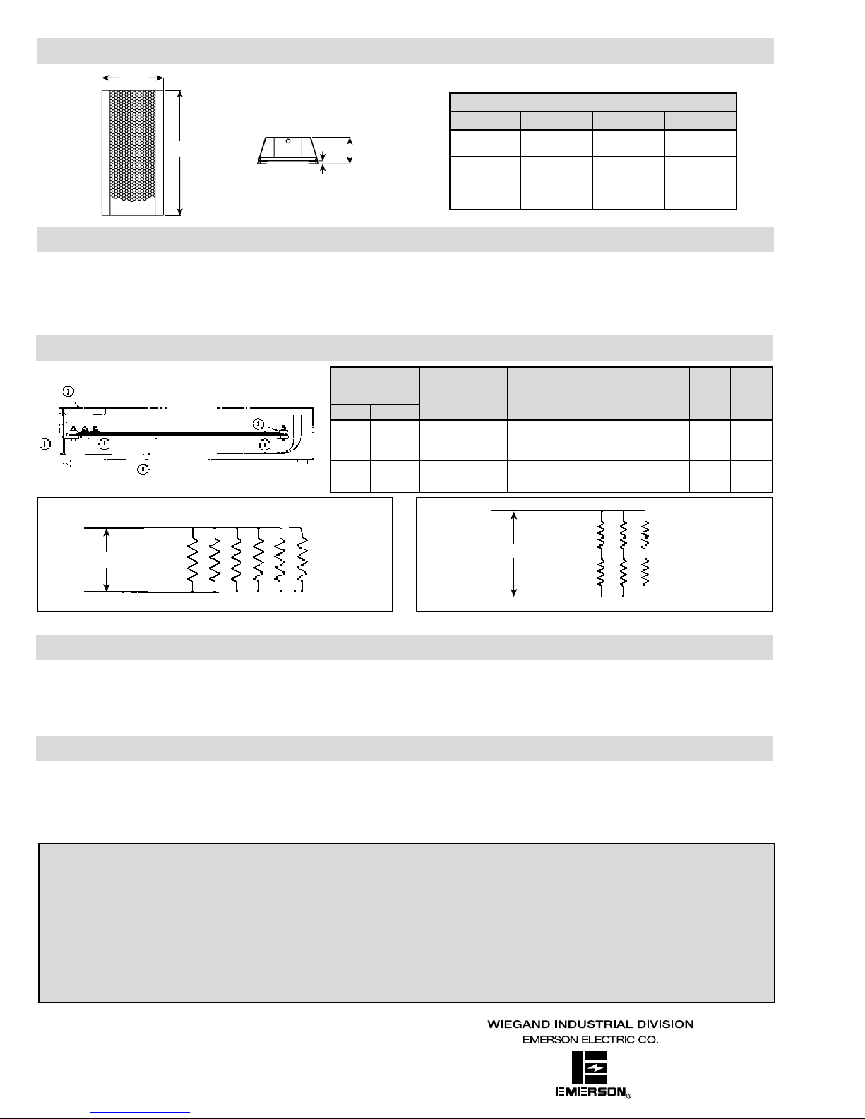
Figure 1 — 240 Volt Heaters Figure 2 — 480 Volt Heaters
1234
Type V
Heating Element Heater Insulating Insulating Wire Wiring
(Iron Sheath) Cover Bushing Bushing Sizes Diagram
Model Volts Watts (Prefix 152-) (Prefix 032-) (Prefix 032-) (90˚C Min) Fig No.
V-2020 240 2000 SE-2450 240V 500W (4) 108259-001 010978-001 (8) 010978-002 (8) #16 1
V-2030 240 3000 SE-2475 240V 750W (4) 108259-001 010978-001 (8) 010978-002 (8) #16 1
V-2030 480 3000 SE-2475 240V 750W (4) 108259-001 010978-001 (8) 010978-002 (8) #16 2
V-2040 240 4500 SE-2475 240V 750W (6) 108259-002 010978-001 (12) 010978-002 (12) #14 1
V-2040 480 4500 SE-2475 240V 750W (6) 108259-002 010978-001 (12) 010978-002 (12) #16 2
Width
5-3/4
Height
3/4
4 or 6 Elements
L1
Line 240V
L2
L1
Line 480V
4 or 6 Elements
L2
 Loading...