

Page 1
Chromalox
®
DIVISION 4 SECTION UB
SALES
REFERENCE
DATE
SERVICE REFERENCE
Installation, Operation
and
RENEWAL PARTS IDENTIFICATION
PF415-10
MARCH, 1999
(Supersedes PF415-9)
161-049029-001
MOUNTING
© 1999 Wiegand Industrial Division, Emerson Electric Co.
Type UB-23E and UB-32E
Forced-Air Heater With or Without Switch
WARNING:
Hazard of Electric Shock. Disconnect all
power before installing heater.
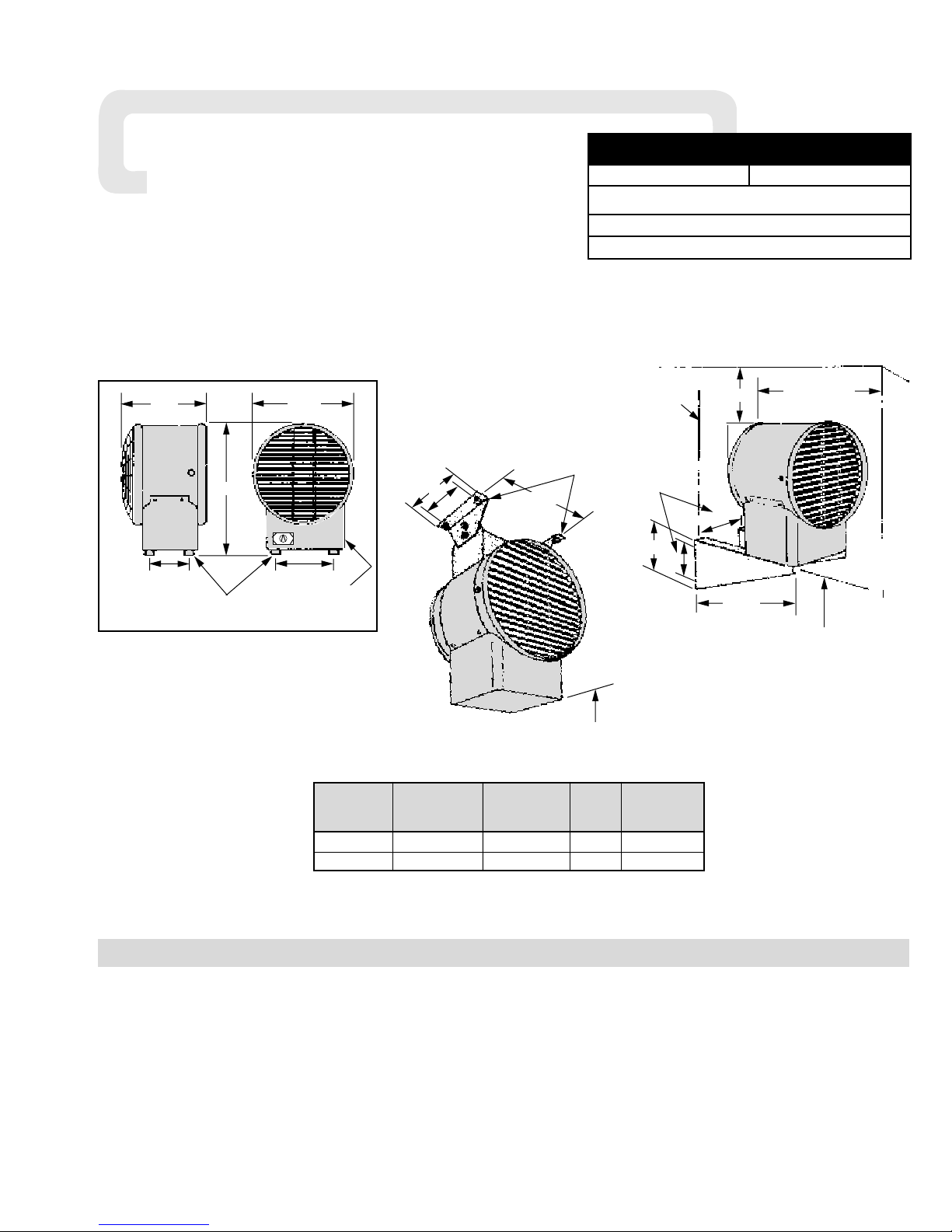
Note: These heaters are designed for wall or ceiling mounting
only. Other modes of mounting voids factory warranty.
1. Height above floor
A.In areas where ceiling height is more than 12 feet, recom-
mended mounting height is approximately 10 feet to underside of heater.
B.For ceiling heights of 12 feet or less, maximum mounting
height is determined by use of ceiling mounting brackets
offered for these heaters. Minimum spacing to ceiling is 3”
(see Figure 2).
C.In either case, the minimum mounting height is 7 feet from
floor to bottom of heater. (See Figures 1 and 2.)
2. Spacing to adjacent walls
A.Rear of case to back wall 4-7/8” minimum (see Figure 2).
B.Side of case to side wall 6” minimum (see Figure 2).
3. If two or more units are operated in the same enclosed space,
their discharges should be directed to aid in development of
mass air movement for uniform heat dispersal.
4. Controlling thermostats to individual heaters should be
mounted at shoulder height on inside walls or columns.
*Note: Model Numbers with suffix “A” added do not include a switch.
Model Numbers with suffix “B” added include a switch
(switch not available on UB-32E rated 120V).
Horizontal
Model* Volts Phase kW Air
Discharge
UB-23E 120, 208, 240 1 2 10’
UB-32E 120, 208, 240 1 3 10’
Specifications —
Dimensions —
Rubber Feet Provided for
Wall Mount Models Only.
7/8” and 1-1/8”
Dia. Holes in Rear
6-1/2”
10-3/8”
13-13/16”
6-1/2”
3”
For Lower Height
from Ceiling:
Customer to add
Extension Strap.
9-1/16”
8”
6”
7’-0” Min. Height
Above Floor
Figure 1
Mounting UB using Ceiling
Mounting Brackets*
Ceiling Line
Wall
Back
Wall
6” Min. Spacing
to Adjacent Wall
3”
4-7/8”
6-1/2”
11-3/8”
7’-0” Min. Height
Above Floor
Mounting
Holes
Center
6”
4”
Figure 2
Mounting UB using Wall
Mounting Brackets*
*Wall and/or Ceiling Mounting Brackets are
available as an accessory option — Contact
local sales representative.
Page 2
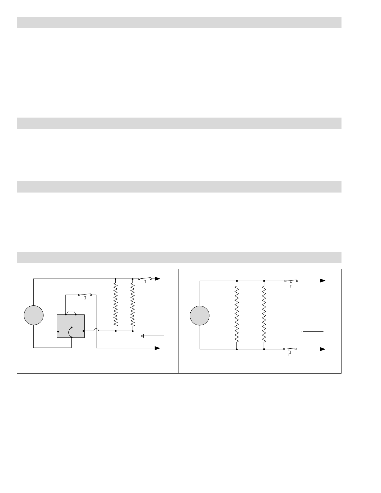
M
G
Cutout
Cutout
(Omit for 120V Heaters)
L2
L1
Heating
Elements
WIRING
Note: All wiring should be done in accordance with local codes
and the National Electrical Code by a qualified person.
WARNING: Hazard of Electric Shock. Any installation involving electric heaters must be effectively
grounded in accordance with the National
Electrical Code to eliminate shock hazard.
1. Connect heater according to the voltage and frequency speci-
fied on the nameplate and using the appropriate wiring diagram (Figures 3 and 4).
2. Motor connections: 120V — white and black, 208/240V —
white and blue. Insulate (wire nut or tape) unused leads.
3. Protection against overheating is provided by an internal auto-
matic thermal cutout which opens the electric circuit if the
normal air-flow is restricted or stopped. Cutout automatically
energizes heater on removal of the obstruction.
WARNING: Users should install adequate back-up
controls and safety devices with their electric
heating equipment. Where the consequences of
failure may be severe, back-up controls are essential. Although the safety of the installation is the
responsibility of the user, Chromalox will be glad
to make equipment recommendations.
OPERATION
DANGER:
1. Do not restrict air-flow through the heater by
placing fabric or other obstructions in front of or
behind the heaters. With some combustible materials, the resulting high discharge temperatures
could cause a fire.
2. This heater is not intended for use in hazardous
atmospheres where flammable vapors, gases, liquids or other combustible atmospheres are present
as defined in the National Electrical Code. Failure
to comply can result in explosion or fire. For these
applications see PDS CXH-EP (PF305).
MAINTENANCE
WARNING: Turn off all power to service heater. Do
not attempt to service heater while unit is operating
as there is hazard of electric shock, injury from
operating fan, and burns from hot heating elements.
1. Fan motors in these heaters are provided with sealed ball bear-
ings, factory lubricated, requiring no further lubrication under
normal service conditions.
2. Following long periods of idleness, heater should be vacuumed
before start-up, to remove accumulated combustible particles
which otherwise may smoke or incinerate on initial heat up.
3. Periodically inspect all electrical connections and terminals to
avoid electrical wiring difficulties. Inspect all wiring for
frayed or worn insulation.
WIRING DIAGRAMS
G
3
Control
Switch
Cutout
Heating
Elements
L1
(Omit for
120V Heaters)
M
2
4
G
1
NL1
L2
Figure 3
For use with UB-23E and UB-32E Type B only (with switch)
Figure 4
For use with UB-23E and UB-32E Type A only (without switch)
Page 3

RENEWAL PARTS IDENTIFICATION
Part numbers or Model Numbers suffixed by a number in ( ) indicates the quantity of same part number used. For prevailing prices of parts shown or for ordering of parts, please contact your local Chromalox Representative.
3 Fan . . . . . . . . . . . . . . . . . . . . . . . . . . . . . . . . . .112-047538-003
4 Thermal Cutout . . . . . . . . . . . . . . . . . . . . . . . .300-057589-001
5 Wall Bracket Set . . . . . . . . . . . . . . . . . . . . . . . .168-026844-001
6 Ceiling Mounting Support Set (Includes 7) . .027-044419-001
7 Ceiling Suspension Brackets . . . . . . . . . . . . . .027-033363-001
(2)
9 Louver . . . . . . . . . . . . . . . . . . . . . . . . . . . . . . .182-047073-001
10 Motor Mounting Frame . . . . . . . . . . . . . . . . . .194-045324-001
11 Grille . . . . . . . . . . . . . . . . . . . . . . . . . . . . . . . .134-119147-001
PARTS COMMON TO ALL HEATERS
1
2
8
Model Voltage Heating Motors Switch
Element (Type B Only)
120 118-045404-001 193-302120-001 292-018604-001
UB-23E 208 118-045404-003 193-302120-001 292-018604-001
240 118-045404-005 193-302120-001 292-018604-001
120 118-045404-002 193-302120-001 ————
UB-32E 208 118-045404-004 193-302120-001 292-018604-001
240 118-045404-006 193-302120-001 292-018604-001
WARNING: Hazard of Electric Shock. Disconnect
all power before servicing these
heaters.
Page 4

Chromalox
®
P R O D U C T S E R V I C E
2150 N. RULON WHITE BLVD., OGDEN, UT 84404
Phone: 1-800-368-2493
99 - 052
TA - Q9 - EF
Litho in U.S.A.
Chromalox warrants only that the Products and parts manufactured by Chromalox, when shipped, and
the work performed by Chromalox when performed, will meet all applicable specification and other specific
product and work requirements (including those of performance), if any, and will be free from defects in
material and workmanship under normal conditions of use. All claims for defective or nonconforming
(both hereinafter called defective) Products, parts or work under this warranty must be made in writing
immediately upon discovery, and in any event, within one (1) year from delivery, provided, however all
claims for defective Products and parts must be made in writing no later than eighteen (18) months after
shipment by Chromalox. Defective and nonconforming items must be held for Chromalox's inspections
and returned to the original f.o.b. point upon request. THE FOREGOING IS EXPRESSLY IN LIEU OF ALL
OTHER WARRANTIES WHATSOEVER, EXPRESS, IMPLIED AND STATUTORY, INCLUDING, WITHOUT
LIMITATION, THE IMPLIED WARRANTIES OF MERCHANTABILITY AND FITNESS FOR A PARTICULAR
PURPOSE.
Notwithstanding the provisions of this WARRANTY AND LIMITATION Clause, it is specifically understood that Products and parts not manufactured and work not performed by Chromalox are warranted only
to the extent and in the manner that the same are warranted to Chromalox by Chromalox's vendors, and
then only to the extent that Chromalox is reasonably able to enforce such warranty, it being understood
Chromalox shall have no obligation to initiate litigation unless Buyer undertakes to pay all cost and expenses therefor, including but not limited to attorney's fees, and indemnifies Chromalox against any liability to
Chromalox's vendors arising out of such litigation.
Upon Buyer's submission of a claim as provided above and its substantiation, Chromalox shall at its
option either (i) repair or replace its Products, parts or work at the original f.o.b. point of delivery or (ii)
refund an equitable portion of the purchase price.
THE FOREGOING IS CHROMALOX'S ONLY OBLIGATION AND BUYER'S EXCLUSIVE REMEDY FOR
BREACH OF WARRANTY, AND IS BUYER'S EXCLUSIVE REMEDY AGAINST CHROMALOX FOR ALL
CLAIMS ARISING HEREUNDER OR RELATING HERETO WHETHER SUCH CLAIMS ARE BASED ON
BREACH OF CONTRACT, TORT (INCLUDING NEGLIGENCE AND STRICT LIABILITY) OR OTHER THEORIES,
BUYER'S FAILURE TO SUBMIT A CLAIM AS PROVIDED ABOVE SHALL SPECIFICALLY WAIVE ALL
CLAIMS FOR DAMAGES OR OTHER RELIEF, INCLUDING BUT NOT LIMITED TO CLAIMS BASED ON
LATENT DEFECTS. IN NO EVENT SHALL BUYER BE ENTITLED TO INCIDENTAL OR CONSEQUENTIAL
DAMAGES AND BUYER SHALL HOLD CHROMALOX HARMLESS THEREFROM. ANY ACTION BY BUYER
ARISING HEREUNDER OR RELATING HERETO, WHETHER BASED ON BREACH OF CONTRACT, TORT
(INCLUDING NEGLIGENCE AND STRICT LIABILITY) OR OTHER THEORIES, MUST BE COMMENCED
WITHIN ONE (1) YEAR AFTER THE DATE OF SHIPMENT OR IT SHALL BE BARRED.
W2008M
WARRANTY AND LIMITATION OF REMEDY AND LIABILITY
 Loading...