

Chromalox TLC-210, TLC-318, TLC-315, TLC-212, TLC-220 Installation, Operating, & Maintenance Instructions
...Page 1
Chromalox
®
DIVISION 4 SECTION
TL
SALES
REFERENCE
DATE
SERVICE REFERENCE
Installation, Operation,
Maintenance Instructions
and
RENEWAL PARTS IDENTIFICATION
PD411-10
AUGUST, 2008
(Supersedes PD411-9)
161-048529-001
Incorporates PD410-8 and PD413-6.
These manuals have been discontinued.
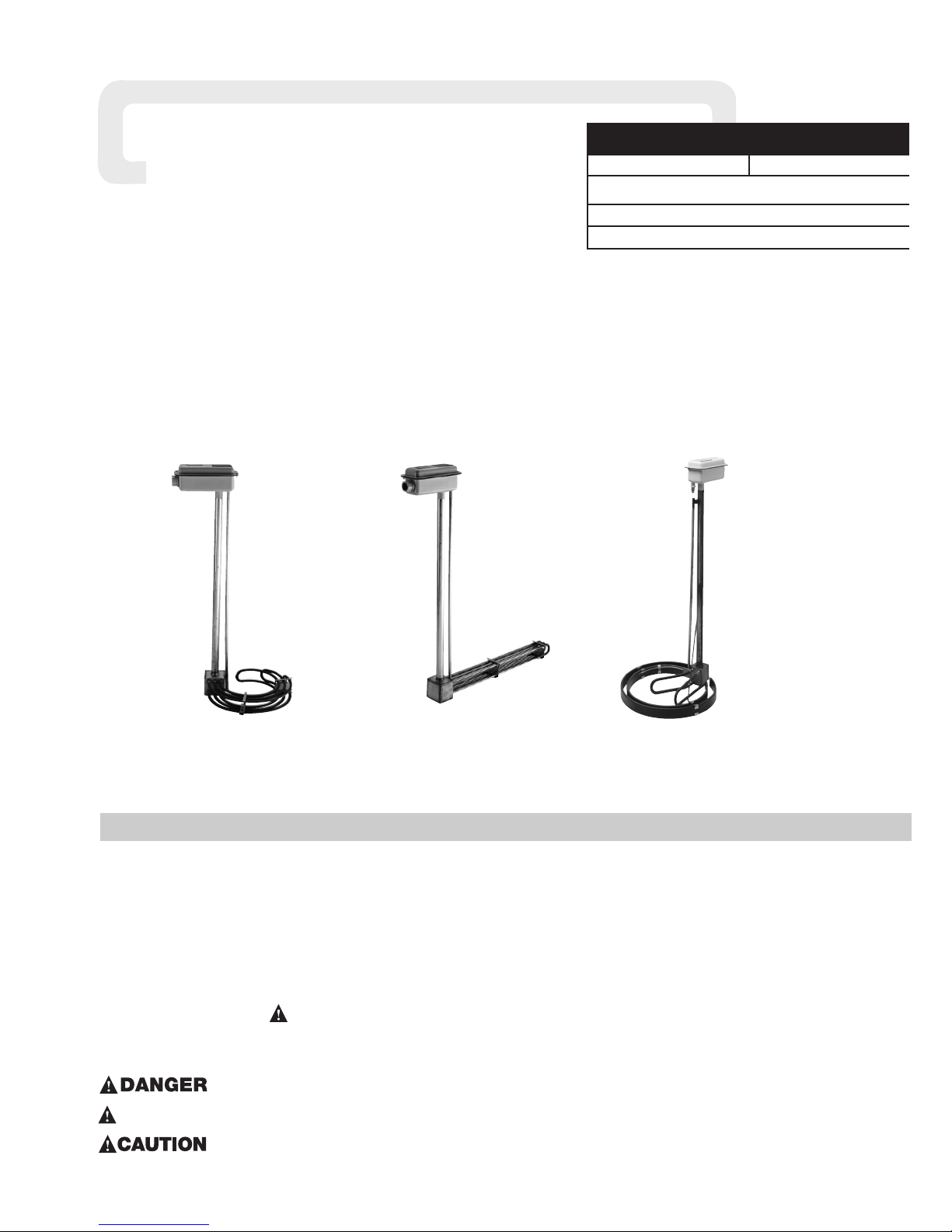
Type TLC, TLO, TLS, TLI, KTLC, KTLO, KTLS,
KTLI, KBLC, KBLS, BLCK, & BLCS Series
Industrial Over-The-Side Immersion Heaters
© 2010 Chromalox, Inc.
Safety Guidelines
The safety and performance of this heater is dependent on proper
handling, installation, control and maintenance. As Chromalox can not
anticipate all conditions under which this information and heater, or
this heater in combination with other manufacturer’s products may be
used, it is advised that you conduct your own tests to determine the
safety and suitability of this heater in combination with other products
in your application. Where the consequences of overheating or failure
could result in personal injury or property damage, back-up controls
and safety devices are essential.
The Safety Alert Symbol: is found throughout these installation instructions to identify potential hazards that can result in personal injury. The seriousness of the potential risk is identified by one of
these three words:
– will result in serious injury or death.
– could result in serious injury or death.
– may result in minor or moderate injury.
Read and follow these instructions to minimize risks of electric
shock or fire. Save these instructions for future reference.
Chromalox Type TLC, TLO,TLS,TLI, KTLC, KTLO, KTLS,
KTLI, KBLC, KBLS, BLCK, & BLCS series industrial Over-TheSide immersion heaters are designed for a wide variety of heating
applications.
1. Heater Construction Characteristics
A. High quality resistance wire held in place by compacted
Magnesium Oxide Refractory or compacted proprietary
cement enclosed in a wide variety of sheath materials.
B. Low to high watt densities.
C. Standard selection of sheath materials include copper, steel,
INCOLOY
®
alloy and stainless steel. This broad selection of
sheath materials will operate successfully in many corrosive
solutions.
GENERAL
Type KTLC
Type TLC
Type KBLS
Shown above are Moisture Resistant Terminal Enclosures. Explosion Resistant Terminal Enclosure not shown.
Note: Consult factory for specific installation instructions for heaters with additional features not detailed in this installation guide.
Such additional features may include thermocouples supplied as a special order modification.
!
!
WARNING
Page 2
2
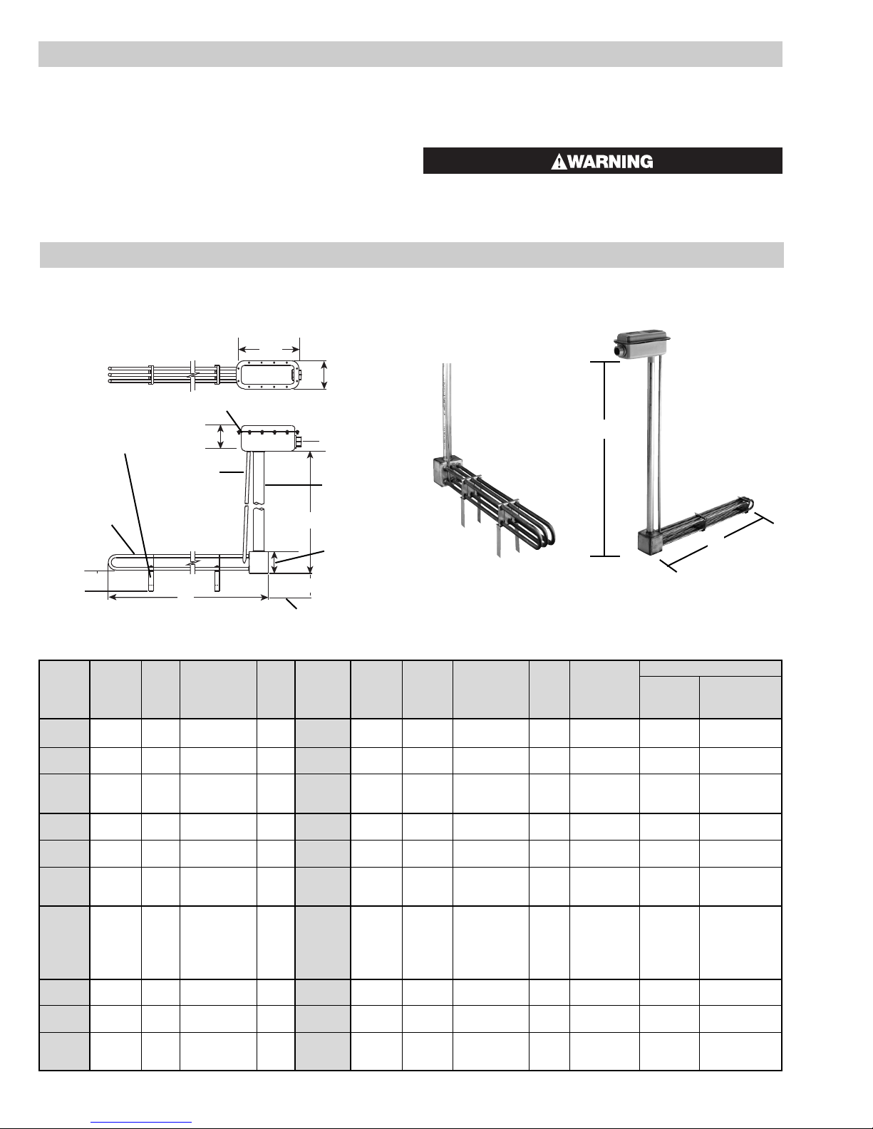
Specifications –
Dimensions (In.)
(A) (B)
No. No. Sheath Min. Tank
Model Elements Phase Volts kW Model Elements Phase Volts kW Material Riser Height Opening Clearance
TLC-210 2 1 240-480 10 TLC-315 3 1 or 3Δ 240-480 15 Copper 48 45
TLC-212 2 1 240-480 12 TLC-318 3 1 or 3Δ 240-480 18 Copper 48 52-1/2
TLC-220 2 1 120-240-480 2 TLC-330 3
1 or 3Δ 120-240
3 Copper 36 12-1/4
1 or 3Y 480
TLC-240 2 1 120-240-480 4 TLC-360 3 1 or 3Δ 120-240-480 6 Copper 36 22-1/4
TLC-260 2 1 120-240-480 6 TLC-390 3 1 or 3Δ 120-240-480 9 Copper 36 29-1/2
TLC-280 2 1 240-480 8 TLC-312 3 1 or 3Δ 240-480 12 Cooper 36, 48 37-3/8
TLI-210 2 1 240-480 10 TLI-315 3 1 or 3Δ 240-480 15 Incoloy 48 45
TLI-212 2 1 240-480 12 TLI-318 3 1 or 3Δ 240-480 18 Incoloy 48 52-1/2
TLI-220 2 1 120-240-480 2 TLI-330 3
1 or 3Δ 120-240
3 Incoloy 36 12-1/4
1 or 3Y 480
TLI-240 2 1 120-240-480 4 TLI-360 3 1 or 3Δ 120-240-480 6 Incoloy 36 22-1/4
TLI-260 2 1 120-240-480 6 TLI-390 3 1 or 3Δ 120-240-480 9 Incoloy 36 29-1/2
TLI-280 2 1 240-480 8 TLI-312 3 1 or 3Δ 240-480 12 Incoloy 36, 48 37-3/8
TLO-220 2 1 120-240-480 2 TLO-330 3 1 or 3Δ 120-240-480 3 Steel 36 22-1/4
TLO-230 2 1 120-240-480 3 TLO-345 3 1 or 3Δ 120-240-480 4.5 Steel 36 29-1/2
TLO-240 2 1 120-240-480 4 TLO-360 3 1 or 3Δ 120-240-480 6 Steel 36, 48 37-3/8
TLO-250 2 1 120-240-480 5 TLO-375 3 1 or 3Δ 120-240-480 7.5 Steel 48 45
TLO-260 2 1 120-240-480 6 TLO-390 3 1 or 3Δ 120-240-480 9 Steel 48 52-1/2
TLO-270 2 1 240-480 7 TLO-310 3 1 or 3Δ 240-480 10 Steel 48 56-1/2
TLS-210 2 1 240-480 10 TLS-315 3 1 or 3Δ 240-480 15 Stainless Steel 48 45
TLS-212 2 1 240-480 12 TLS-318 3 1 or 3Δ 240-480 18 Stainless Steel 48 52-1/2
TLS-220 2 1 120-240-480 2 TLS-330 3
1 or 3Δ 120-240
3 Stainless Steel 36 12-1/4
1 or 3Y 480
TLS-240 2 1 120-240-480 4 TLS-360 3 1 or 3Δ 120-240-480 6 Stainless Steel 36 22-1/4
TLS-260 2 1 120-240-480 6 TLS-390 3 1 or 3Δ 120-240-480 9 Stainless Steel 36 29-1/2
TLS-280 2 1 240-480 8 TLS-312 3 1 or 3Δ 240-480 12 Stainless Steel 36, 48 37-3/8
(A)
(B)
Note: Thermostat shipped separately in kit. See page
with renewal parts for ordering information.
(10)
(A)
(B)
(4)
(4-1/2)
(3-1/2)
3-1/2 approx.
Tank Bottom
1”–11-1/2 NPT
Tube Riser
Gasket
Thermostat Well
Heating Elements
Sludge Leg/s
Assemble
As Shown
(See Installation)
(4-1/16)
TLC, TLO, TLS, TLI
SPECIFICATIONS
GENERAL (cont’d.)
D. Riser type construction puts the heat at the bottom inducing
natural “stirring action” and evenly distributed temperatures.
E. Units are available with E1 General Purpose, E4 Moisture
Resistant, E2 Explosion/Moisture Resistant and E3 Explosion
Resistant terminal enclosures.
IMPORTANT: It is the responsibility of the purchaser of
the heater to make the ultimate choice of sheath
material based upon his knowledge of the chemical
composition of the corrosive solution, character of
the materials entering the solution, and controls
which he maintains on the process. CHROMALOX
cannot warrant any electric immersion heater against
failure by sheath corrosion if such failure is the result
of operating conditions beyond our control.
Sheath corrosion can result in a ground fault which,
depending upon the solution being heated, can cause
an explosion or fire.
Page 3
DIMENSIONS
Inches
(A) (B)
Kw Riser
Min. Opening
Model Volts (11 WPSI) Height Clearance
Type KBLC – Steel Construction
KBLC-24 120 or 240 2.2 36 12-3/4
KBLC-24T2 120 or 240 2.2 36 12-3/4
KBLC-24T3 120 or 240 2.2 36 12-3/4
KBLC-28 240 only 4.4 36 17-3/4
KBLC-28T2 240 only 4.4 36 17-3/4
KBLC-28T3 240 only 4.4 36 17-3/4
Type KBLS – Stainless Steel Construction
KBLS-244 120 or 240 2.2 36 12-3/4
KBLS-244T1 120 or 240 2.2 36 12-3/4
KBLS-244T2 120 or 240 2.2 36 12-3/4
KBLS-244T3 120 or 240 2.2 36 12-3/4
KBLS-288 240 only 4.4 36 17-3/4
KBLS-288T1 240 only 4.4 36 17-3/4
KBLS-288T2 240 only 4.4 36 17-3/4
KBLS-288T3 240 only 4.4 36 17-3/4
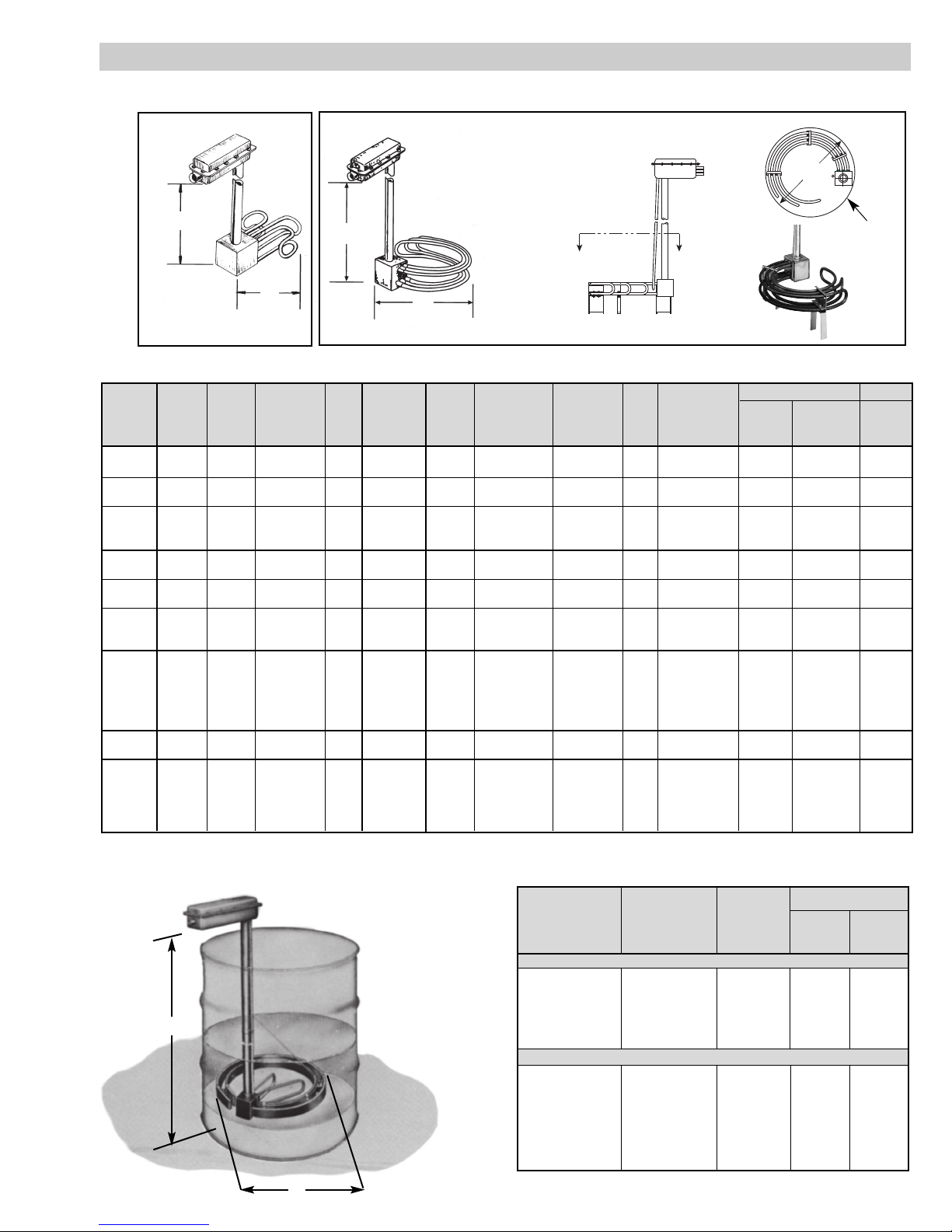
3
Specifications –
(A)
(B)
KBLC, KBLS
KTLC, KTLI, KTLO, KTLS
Specifications –
Dimensions (In.)
(A) Standard
(B) Min. Element
No. No. Sheath Riser Tank Opening Arrange-
Model Elements Phase Volts kW Model Elements Phase Volts kW Material Height Clearance ment
KTLC-210 2 1 240-480 10 KTLC-315 3 1 or 3Δz 240-480 15 Copper 48 21-1/4 Fig. 2
KTLC-212 2 1 240-480 12 KTLC-318 3 1 or 3Δz 240-480 18 Copper 48 23-1/2 Fig. 2
KTLC-220 2 1 120-240-480 2 KTLC-330 3
1 or 3Δz 120-240
3 Copper 36 10-5/8 Fig. 1
1 or 3Y 480
KTLC-240 2 1 120-240-480 4 KTLC-360 3 1 or 3Δ 120-240-480 6 Copper 36 13-3/4 Fig. 2
KTLC-260 2 1 120-240-480 6 KTLC-390 3 1 or 3Δ 120-240-480 9 Copper 36 16-1/8 Fig. 2
KTLC-280 2 1 240-480 8 KTLC-312 3 1 or 3Δ 240-480 12 Cooper 36, 48 18-5/8 Fig. 2
KTLI-210 2 1 240-480 10 KTLI-315 3 1 or 3Δ 240-480 15 Incoloy 48 21-1/4 Fig. 2
KTLI-212 2 1 240-480 12 KTLI-318 3 1 or 3Δ 240-480 18 Incoloy 48 23-1/2 Fig. 2
KTLI-220 2 1 120-240-480 2 KTLI-330 3
1 or 3Δ 120-240
3 Incoloy 36 10-5/8 Fig. 1
1 or 3Y 480
KTLI-240 2 1 120-240-480 4 KTLI-360 3 1 or 3Δ 120-240-480 6 Incoloy 36 13-3/4 Fig. 2
KTLI-260 2 1 120-240-480 6 KTLI-390 3 1 or 3Δ 120-240-480 9 Incoloy 36 16-1/8 Fig. 2
KTLI-280 2 1 240-480 8 KTLI-312 3 1 or 3Δ 240-480 12 Incoloy 36, 48 18-5/8 Fig. 2
KTLO-220 2 1 120-240-480 2 KTLO-330 3 1 or 3Δ 120-240-480 3 Steel 36 13-3/4 Fig. 2
KTLO-230 2 1 120-240-480 3 KTLO-345 3 1 or 3Δ 120-240-480 4.5 Steel 36 16-1/8 Fig. 2
KTLO-240 2 1 120-240-480 4 KTLO-360 3 1 or 3Δ 120-240-480 6 Steel 36, 48 18-5/8 Fig. 2
KTLO-250 2 1 120-240-480 5 KTLO-375 3 1 or 3Δ 120-240-480 7.5 Steel 48 21-1/4 Fig. 2
KTLO-260 2 1 120-240-480 6 KTLO-390 3 1 or 3Δ 120-240-480 9 Steel 48 23-1/2 Fig. 2
KTLO-270 2 1 240-480 7 KTLO-310 3 1 or 3Δ 240-480 10 Steel 48 24-7/8 Fig. 2
KTLS-210 2 1 240-480 10 KTLS-315 3 1 or 3Δ 240-480 15 Stainless Steel 48 21-1/4 Fig. 2
KTLS-212 2 1 240-480 12 KTLS-318 3 1 or 3Δ 240-480 18 Stainless Steel 48 23-1/2 Fig. 2
KTLS-220 2 1 120-240-480 2 KTLS-330 3
1 or 3Δ 120-240
3 Stainless Steel 36 10-5/8 Fig. 1
1 or 3Y 480
KTLS-240 2 1 120-240-480 4 KTLS-360 3 1 or 3Δ 120-240-480 6 Stainless Steel 36 13-3/4 Fig. 2
KTLS-260 2 1 120-240-480 6 KTLS-390 3 1 or 3Δ 120-240-480 9 Stainless Steel 36 16-1/8 Fig. 2
KTLS-280 2 1 240-480 8 KTLS-312 3 1 or 3Δ 240-480 12 Stainless Steel 36, 48 18-5/8 Fig. 2
(A)
(A)
(B)
(B)
Figure 1
Figure 2
A
(B)
A
Section A-A
Min. Tank
Clearance
SPECIFICATIONS (cont’d.)
Page 4

FIRE HAZARD. An integral thermostat, if provided,
is designed for temperature control service only.
Because the thermostat does not fail safe, it should
not be used for temperature limiting duty. Wiring to
this device is the responsibility of the user.
The system designer is responsible for the safety
of this equipment and should install adequate
back-up controls and safety devices with their
electric heating equipment. Where the consequences of failure could result in personal injury or
property damage, back-up controls are essential.
FIRE/EXPLOSION HAZARD. Use only Explosion
Resistant Enclosures (E2, E3 or ER) in hazardous
atmospheres where flammable vapors, gases, liquids
or other combustible atmospheres are present as
defined in the National Electrical Code (NFPA 70).
Failure to comply could result in personal injury or
property damage.
ELECTRIC SHOCK HAZARD. Disconnect all power
before installing or servicing heater. Failure to do
so could result in personal injury or property damage. Heater must be installed by a qualified person
in accordance with the National Electrical Code,
NFPA 70.
1. Before installing, check your Over-The-Side heater for any dam-
age that may have occurred during shipment. Also, check to ensure
that the line voltage is the same as that stamped on the nameplate.
2.
Do not bend heating elements. If bending is necessary, consult factory.
3. IMPORTANT: Mount the heater in the tank so that the liquid
level will always be above the effective heated portion of the
heater. If the heater is not properly submerged, it will overheat and
damage the heating elements and create a possible fire hazard due
to excessive sheath temperatures. See “Warning” under
“Installation” section. (see Figure 3).
4. Heater must be supported from tank bottom. Heater must not be
operated in sludge. Sludge legs can be provided. Assemble as
shown in Figure 3.
5. Where work will pass over or near equipment, additional protec-
tion, such as a metal guard, may be needed.
6. In the electroplating operation the heaters are not, under any cir-
cumstance, to be placed between the electrodes and the work.
7. When melting solids by direct immersion, a surface vent should be
provided to allow gases to escape. Operate the heater on half voltage until melted material completely covers the heater area.
8. A drip loop is recommended to minimize passage of moisture
along wiring into terminal enclosure and connections.
FIRE HAZARD. Since heaters are capable of developing
high temperatures, extreme care should be taken to:
A. Use explosion-resistant terminal enclosures in hazardous loca-
tions. Consult Chromalox for selection of explosion-resistant
terminal enclosures for hazardous locations.
B. Avoid contact between heater and combustible materials.
C. Keep combustible materials far enough away to be free of the
effects of high temperatures.
FREEZE HAZARD. Some Over-The-Side heaters are
equipped with a thermowell for process control or
over-temperature control. Do not allow moisture to
accumulate in thermowell. Freezing temperatures
can cause damage that may result in the heated
medium leaking into terminal enclosure.
INSTALLATION
4
Specifications –
Kilowats Dimensions (In.)
No. Regular Oil Fuel Oil (A) (B) Min. Tank
Model Blades Phase 18 W/in
2
12 W/in
2
40 W/in
2
Voltage Riser Height
Opening Clearance
(C)
BLCK-MH618 6 1 or 3 ⌬ 12 7.5 – 240 or 480 144 16-1/2 8-7/8
BLCK-MH824 8 1 or 3 ⌬ 16 10 – 240 or 480 144 16-1/2 12
BLCK-MH103 10 1 or 3 ⌬ 20 12.5 – 240 or 480 144 16-1/2 15-1/8
BLCK-MH236 12 1 or 3 ⌬ 24 15 – 240 or 480 144 16-1/2 18-1/4
BLCS-618 6 1 or 3 ⌬ 12 7.5 – 240 or 480 144 34 8-7/8
BLCS-824 8 1 or 3 ⌬ 16 10 – 240 or 480 144 34 12
BLCS-1030 10 1 or 3 ⌬ 20 12.5 – 240 or 480 144 34 15-1/8
BLCS-1236 12 1 or 3 ⌬ 24 15 – 240 or 480 144 34 18-1/4
BLCK, BLCS
4 to 12 Blades
Type BLCK-MH
1-1/4” Ground Joint
Malleable Iron Union
1-1/4” Round
Floor Flange
Malleable Iron
1-1/4” Steel
Pipe Riser
Type BLCS
1-1/4” Pipe Opening
(4-5/32)
of Mtg. Hole
same as Dim. “A”
Suspension Bracket
4 to 12 Blades
C
L
(C)
(B)
(A)
(A)
(C)
(B)
!
SPECIFICATIONS (cont’d.)
Page 5

ELECTRIC SHOCK HAZARD. Any installation involving electric heaters must be performed by a qualified person and must be effectively grounded in
accordance with the National Electrical Code to
eliminate shock hazard.
1. Electric wiring to heater must be installed in accordance with the
National Electrical Code and with local codes by a qualified person. CAUTION: Use copper conductors only.
2. When element wattages are not equal, heaters must not be con-
nected in series.
3. Electrical wiring to heater should be contained in rigid conduit or
in sealed flexible conduit to keep corrosive vapors and liquids out
of the terminal enclosure. If high humidity is encountered, the conduit should slope away from the heater.
4. If flexible cord is employed, a watertight connector should be used
for entry of the cord into the terminal enclosure. Outdoor applications require liquid-tight conduit and connectors.
5. Bring the power line wires through the opening in the terminal
enclosure.
6. Heaters are prewired and tagged for easy installation of electrical
wiring to the heater. Tagging of the individual circuits of
Chromalox Industrial Over-The-Side Immersion heaters is shown
in the following tabulations. Refers to Type TLC, TLO, TLS, TLI,
KTLC, KTLO, KTLS, KTLI, KBLC, KBLS, BLCK, and BLCS
Series heaters.
7. Make sure heater, is grounded by attaching ground conductor,
traceable back to service entrance, to the ground terminal located
inside the terminal enclosure. If heater is used in an electroplating
tank, the heater should be grounded externally to the tank wall to
minimize stray plating currents in heater sheath that may cause
sheath corrosion.
8. Check for loose terminal connections and tighten if necessary.
Made to order items are prewired and tagged at the factory. Wiring
of made to order items may differ from those shown in the tabulations. Carefully check voltage and phase on the heater name-
plate and select either the appropriate wiring shown above or
check for the appropriate wiring diagram in the heater terminal enclosure. For reference purposes, some typical wiring dia-
grams are shown in the following figures.
5
WIRING
WIRING DIAGRAMS – TLC, TLO, TLS, TLI
120V 120V 240V 240V 480V 480V 480V 120V 120V 240V 240V 480V 480V 480V
Model 1ø 3øΔz 1ø 3øΔz 1ø 3øΔz 3øY Model 1ø 3øΔz 1ø 3øΔz 1ø 3øΔz 3øY
Fig. Fig. Fig. Fig. Fig. Fig. Fig. Fig. Fig. Fig. Fig. Fig. Fig. Fig.
TLC, TLI and TLS 210 — — 1 — 1 — — TLO 310 — — 3 4 3 4 —
TLC, TLI and TLS 212 — — 1 — 1 — — TLC, TLI and TLS 312 — — 3 4 3 4 —
TLC, TLI, TLO and TLS 220 1 — 1 — 2 — — TLC, TLI and TLS 315 — — 3 4 3 4 —
TLO 230 1 — 1 — 1 — — TLC, TLI and TLS 318 — 3 4 3 4 —
TLC, TLI, TLO and TLS 240 1 — 1 — 1 — — TLC, TLI, TLO and TLS 330 3 4 3 4 5 4 6
TLO 250 1 — 1 — 1 — — TLO 345 3 4 3 4 3 4 —
TLC, TLI, TLO and TLS 260 1 — 1 — 1 — — TLC, TLI, TLO and TLS 360 3 4 3 4 3 4 —
TLO 270 — — 1 — 1 — — TLO 375 3 4 3 4 3 4 —
TLC, TLI and TLS 280 — — 1 — 1 — — TLC, TLI, TLO and TLS 390 3 4 3 4 3 4 —
Note: Use wire size and type specified by NEC.
480V heaters require 600V wire per NEC.
480V heaters require a contactor.
Contactor and wiring supplied by customer.
INSTALLATION (cont’d.)
9. To prevent moisture accumulation in cryogenic applications or
when heater is exposed to freezing temperatures:
A. Slope conduit away from enclosure (drip loop).
B. Seal all conduit openings to moisture/explosion resistant ter-
minal enclosure.
C. Insulate terminal enclosure.
FIRE OR SHOCK HAZARD. Moisture accumulation
in the element refractory material, element overtemperature, or sheath corrosion can cause
ground fault to the element sheath, generating arcing and molten metal. Install Ground Fault CircuitInterrupter (GFCI) to prevent personal injury or
Equipment Ground Fault Protection to prevent
property damage.
10. Heaters with floor flange:
A. Remove electrical enclosure.
B. Mount heater to tank or manhole cover.
C. Install electrical enclosure.
Fittings into electrical enclosure must be properly
sealed to prevent contamination of electrical contacts from vapors.
FIRE OR EXPLOSION HAZARD. If the heater is not
properly submerged, the heating elements will overheat and could result in a fire or damaged equipment.
NOTE: If heating in closed vessels, controls and
backup controls must be used to prevent buildup of
temperature and/or pressure. Maximum pressure
rating is 50 PSI.
Drip Loop recommended to
minimize passage of moisture
along wiring into terminal
wiring connections.
Expected Low Liquid Level
Always maintain a minimum of
6 to 8" of liquid above the heated
portion of the element to prevent
exposure of the effective
heated length.
Expected maximum
sediment level
Sludge Legs
NOTE: Locate the heater as low as possible for maximum
heated liquid storage capacity. Heat does not move downward.
6 to 8"
Minimum
Suitable Wiring
FIGURE 3 Open Tank Illustration
!
Page 6

6
120V
or
240V
Contactor
Thermostat
Low
Liquid
Control
L1
L2
Term. Block
Junction Box
Factory
Field
120V
or
240V
Contactor
Thermostat
Low
Liquid
Control
L1
L2
Term. Block
Junction Box
L3
Factory
Field
WIRING DIAGRAM 3
WIRING DIAGRAM 4
120V
or
240V
Contactor
Thermostat
Low
Liquid
Control
L1
L2
Term. Block
Junction Box
Factory
Field
120V
or
240V
Contactor
Thermostat
Low
Liquid
Control
L1
L2
Term. Block
Junction Box
Factory
Field
WIRING DIAGRAM 2
WIRING DIAGRAM 1
120V 120V 240V 240V 480V 480V 480V 120V 120V 240V 240V 480V 480V 480V
Model 1ø 3øΔz 1ø 3øΔz 1ø 3øΔz 3øY Model 1ø 3øΔz 1ø 3øΔz 1ø 3øΔz 3øY
Fig. Fig. Fig. Fig. Fig. Fig. Fig. Fig. Fig. Fig. Fig. Fig. Fig. Fig.
KTLC, KTLI and KTLS 210 — — 1 — 1 — — KTLO 310 — — 3 4 3 4 —
KTLC, KTLI and KTLS 212 — — 1 — 1 — — KTLC, KTLI and KTLS 312 — — 3 4 3 4 —
KTLC, KTLI, KTLO and KTLS 220 1 — 1 — 2 — — KTLC, KTLI and KTLS 315 — — 3 4 3 4 —
KTLO 230 1 — 1 — 1 — — KTLC, KTLI and KTLS 318 — 3 4 3 4 —
KTLC, KTLI, KTLO and KTLS 240 1 — 1 — 1 — — KTLC, KTLI, KTLO and KTLS 330 3 4 3 4 5 4 6
KTLO 250 1 — 1 — 1 — — KTLO 345 3 4 3 4 3 4 —
KTLC, KTLI, KTLO and KTLS 260 1 — 1 — 1 — — KTLC, KTLI, KTLO and KTLS 360 3 4 3 4 3 4 —
KTLO 270 — — 1 — 1 — — KTLO 375 3 4 3 4 3 4 —
KTLC, KTLI and KTLS 280 — — 1 — 1 — — KTLC, KTLI, KTLO and KTLS 390 3 4 3 4 3 4 —
Note: Use wire size and type specified by NEC.
480V heaters require 600V wire per NEC.
480V heaters require a contactor.
Contactor and wiring supplied by customer.
WIRING DIAGRAMS – KTLC, KTLO, KTLS, KTLI
120V 120V 240V 240V 480V 480V 480V 120V 120V 240V 240V 480V 480V 480V
Model 1ø 3øΔz 1ø 3øΔz 1ø 3øΔz 3øY Model 1ø 3øΔz 1ø 3øΔz 1ø 3øΔz 3øY
Fig. Fig. Fig. Fig. Fig. Fig. Fig. Fig. Fig. Fig. Fig. Fig. Fig. Fig.
BLCK — — 1 4 1 4 — BLCS — — 7 8 7 8 —
Note: Use wire size and type specified by NEC.
480V heaters require 600V wire per NEC.
480V heaters require a contactor.
Contactor and wiring supplied by customer.
WIRING DIAGRAMS – BLCK, BLCS
Page 7

7
1. Do not operate heater at voltages in excess of that stamped on the
heater since excess voltage will shorten heater life.
2. Always maintain a minimum of 6 to 8” of liquid above the heated
portion of the element to prevent exposure of the effective heated
length. If the heater is not properly submerged, it will overheat and
shorten heater life. DO NOT OPERATE HEATER IF DRY.
3. Keep heating elements above sediment deposits.
4. Low Megohm Condition — The refractory material used in elec-
tric heaters may absorb moisture during transit, storage or when
subject to humid environments that will reduce the cold insulation
resistance (low megohm). Low megohm may result in a high leakage current to ground and nuisance trips of ground fault protection
equipment. Normally, the megohm value increases after heat-up.
Typical insulation valves are 5 megohm or greater on complete
assemblies or 20 megohm on individual unsealed elements. It is
recommended that heaters with 1 megohm or less be dried out
before applying full power. If dried properly, low megohm will not
effect heater life or efficiency.
To correct a low megohm condition, remove terminal enclosure
cover, gaskets, and terminal hardware. Bake heaters in an oven at
300 to 500˚F for several hours or preferably overnight.
An alternate procedure is to cycle the heater in 10 to 15 minute
periods at low voltage until megohm values are normal. Sheath
temperatures should not exceed 350˚F.
NOTE: Low megohm on heating elements with epoxy or hermetic
seals cannot be serviced in the field. Typical resistance values when sealed are 200 megohm or greater. Contact Chromalox service center at number listed.
OPERATION
Term. Block
Contactor
L1
L2
Thermostat
Junction Box
120V
or
240V
Low
Liquid
Control
Factory
Field
Term. Block
Contactor
L1
L2
Thermostat
Junction Box
120V
or
240V
Low
Liquid
Control
Factory
Field
L3
WIRING DIAGRAM 7
WIRING DIAGRAM 8
Factory
Field
120V
or
240V
Contactor
Thermostat
Low
Liquid
Control
L1
L2
Term. Block
Junction Box
L3
120V
or
240V
Contactor
Thermostat
Low
Liquid
Control
L1
L2
Term. Block
Junction Box
Factory
Field
WIRING DIAGRAM 6
WIRING DIAGRAM 5
Page 8

TA -V7 - EF
Litho in U.S.A.
2150 N. RULON WHITE BLVD., OGDEN, UT 84404
Phone: 1-800-368-2493 www.chromalox.com
MAINTENANCE
RENEWAL PARTS
ELECTRIC SHOCK HAZARD. Disconnect all power
before installing or servicing heater. Failure to do so
could result in personal injury or property damage.
1. Heaters should be checked periodically for coatings and corrosion
and cleaned if necessary.
2. The tank should be checked regularly for sediment around the
heater as sediment can act as an insulator and shorten heater life.
Note: Applies to all items, not just #2.
Note: User is responsible for maintenance schedule based on their
knowledge of the heated medium and operating conditions.
3. Remove any accumulated sludge deposits from heater and from
tank.
4. Check for loose terminal connections.
5. If corrosion is indicated in the terminal enclosure, check termi-
nal enclosure gasket and replace if necessary. Check conduit
layout to correct conditions that allow corrosion to enter the terminal enclosure.
6. Clean terminal ends of all contamination.
1. Thermostat Kit (order by PCN):
A. 0-100°F . . . . . . . . . . . . . . . . . . . . . . . . . . . . . . . . .PCN 277835
B. 60-250°F . . . . . . . . . . . . . . . . . . . . . . . . . . . . . . . .PCN 277819
2. Thermostat Knob:
A. 0-100°F . . . . . . . . . . . . . . . . . . . . . . . . . . . . . .169-019605-002
B. 60-250°F . . . . . . . . . . . . . . . . . . . . . . . . . . . . .169-019604-001
C. 200-550˚F . . . . . . . . . . . . . . . . . . . . . . . . . . . .169-019604-002
3. Sludge Legs:
A. TLC, KTLC Series . . . . . . . . . . . . . . . . . . . . . .176-114713-001
B. TLI, KTLI Series . . . . . . . . . . . . . . . . . . . . . . .176-114713-001
C. TLO, KTLO Series . . . . . . . . . . . . . . . . . . . . . .176-114713-002
D.TLS, KTLS Series . . . . . . . . . . . . . . . . . . . . . .176-114713-003
Gasket . . . . . . . . . . . . . . . . . . . . . . . . . . . . . . . . . . .132-012603-004
Cover . . . . . . . . . . . . . . . . . . . . . . . . . . . . . . . . . . . .080-012602-001
4 Post Terminal Block . . . . . . . . . . . . . . . . . . . . . . .303-001843-001
3 Post Terminal Block . . . . . . . . . . . . . . . . . . . . . . .303-006621-003
Thermostat Mounting Bracket . . . . . . . . . . . . . . . . .027-072456-001
4. Thermostat
A. 0-100°F (84” Capillary) . . . . . . . . . . . . . . . . . .300-048518-005
B. 60-250°F (84” Capillary) . . . . . . . . . . . . . . . . .300-048518-002
C. 200-550˚F (84” Capillary) . . . . . . . . . . . . . . . .300-048518-004
D.0-100°F (144” Capillary) . . . . . . . . . . . . . . . . .300-048518-019
E. 60-250°F (180” Capillary) . . . . . . . . . . . . . . . .300-048518-022
F. 200-550˚F (180” Capillary) . . . . . . . . . . . . . . .300-048518-023
Limited Warranty:
Please refer to the Chromalox limited warranty applicable to this product at
http://www.chromalox.com/customer-service/policies/termsofsale.aspx.
 Loading...