

Page 1
Chromalox
®
DIVISION 4 SECTION
RT
SALES
REFERENCE
DATE
SERVICE REFERENCE
Installation Instructions
PJ451-11
161-562762-001
MARCH, 2009
(Supersedes PJ451-10)
RTPC Power Connection Kit for Self-Regulating
and Constant Wattage Rapid-Trace Heating Cable
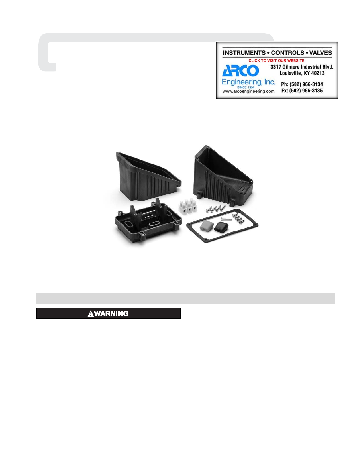
RTPC Power Connection Kit Parts:
1 - Molded Junction Box consisting of:
Base - Box - Lid - Hardware
1 - Three Position Terminal Block
1 - Mounting Screw for Terminal Block
1 - Black Cable Grommet
1 - Orange Cable Grommet
1 - Cover Gasket
ELECTRIC SHOCK HAZARD. Disconnect all power
before installing or servicing heating cable and
accessories. A qualified person must perform
installation and service of heating cable and
accessories. Heating cable must be effectively
grounded in accordance with the National
Electrical Code. Failure to comply can result in
personal injury or property damage.
NOTE: All electrical wiring, including GFCI (Ground Fault
Circuit Interrupters), must be done according to National
Electrical or local codes by a qualified person.
The RTPC Kit is used to connect base, braided (-C) and overcoated (-CR or -CT) versions of Self-Regulating and Fluoropolymer
insulated Constant Wattage Rapid-Trace Heating Cables to power.
© 2010 Chromalox, Inc.
GENERAL
The cable grommet is furnished with this kit, such that the black
grommet is used for self-regulating cables SRL, SRF, SRM/E,
SRL/S, SRMF/S and the orange grommet is used for constant
wattage cable CWM and self-regulating cable SRS.
Each kit contains enough material to make one power connection point. It is possible to connect up to three Self-Regulating or
two Constant Wattage Cables in the same box. (One grommet
required for each cable.)
Materials required for installation include: standard electrical
cutters, screwdriver, sharp utility knife and a pipe strap
(Chromalox PS or equal).
Wipe inside lip of cover with a clean cloth. Remove protective
backing from the gasket and affix it to the cover lip. Press firmly
all around for proper adhesion.
Page 2
INSTALLATION
NOTE: These instructions are for all Self-Regulating and
Constant Wattage heating cables in ordinary locations. Consult
factory for installation of braided cable in hazardous locations.
Not all instructions are for all cables. Each step of the instructions
will have a heading in boldface stating what type of cable each
instruction is intended for.
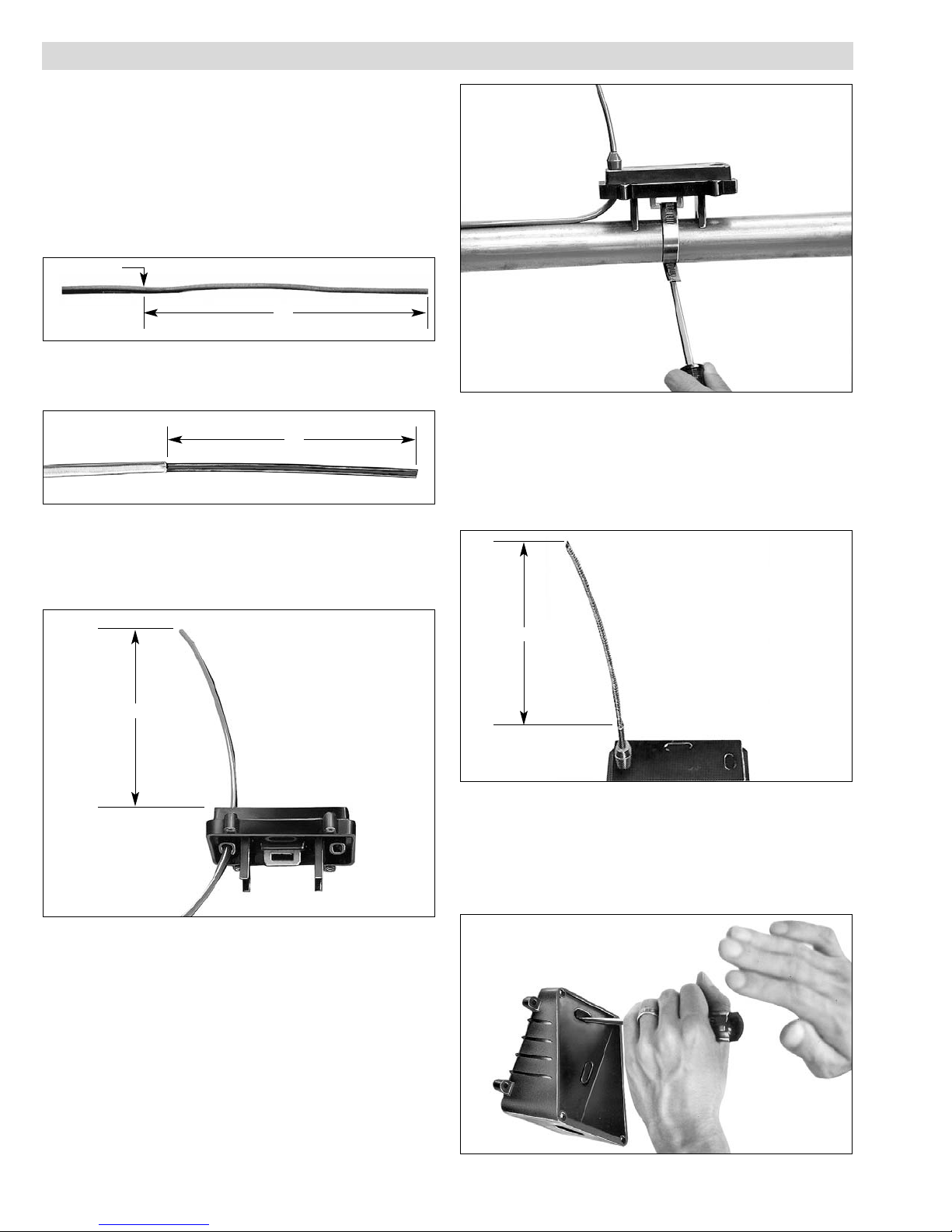
1. FOR CONSTANT WATTAGE CABLES:
Cut the cable 12 inches past the last module point (indentation
in cable). NOTE: Cutting the cable between module points
creates a non-heating cold lead. See Figure 1.
Module Point
12”
Figure 1
2. FOR CABLE WITH EXPOSED METAL BRAID (-C):
Push the braid back 12 inches on the cable. See Figure 2.
12”
Figure 2
Figure 4
5. FOR OVERCOATED CABLES (-CR or -CT):
Score the outer insulation seven (7) inches from the end of
cable. Remove the jacket to expose the metal braid. See Figure 5.
CAUTION: When removing the outer jacket, be
careful not to damage the braid or the base
cable insulation.
3. FOR ALL CABLES:
Feed the ends of the cables through the appropriate hole in
the base. Allow eight (8) inches of cable to extend above the
top of the base. See Figure 3.
8”
Figure 3
4. FOR ALL CABLES:
Slide cable grommet over the end of the cable and insert it
into the opening in the base. Secure the base to the pipe by
threading the appropriate sized pipestrap through the slot in
the mounting plate. Tighten the pipestrap until the base is
securely attached to the pipe. See Figure 4.
7”
Figure 5
6. FOR ALL CABLES:
Punch out the knockouts on the bottom of the box which correspond to the openings in the base through which the heating
cable passes. Be careful to punch out only those knockouts to
be used. If one is mistakenly punched, blank grommets can be
ordered to re-establish the water tight seal. See Figure 6.
Figure 6
Page 3

INSTALLATION
7. FOR ALL CABLES:
Feed the cables through the corresponding holes in the box.
Secure box to base using all four (8-32) screws. See Figure 7.
#8/32 Screw
Figure 7
8. FOR OVERCOATED CABLES:
Starting from the end of the cable, unravel 2-1/2 inches of the
braid. Twist the strands together to form a pigtail. See Figure 8.
2-1/2”
described above. Separate the buss wires and strip off the last
3/8 inch of insulation from both buss wires. See Figure 10.
3/4”
3/8”
Figure 10
11. FOR ALL CABLES:
Insert the bared ends of the conductors into the openings in
the terminal block. Tighten screws firmly to hold conductors
in place. See Figure 11.
Figure 8
9. FOR SELF-REGULATING CABLES:
Using standard electrical cutters, cut a 3/4 inch long notch out
of the cable between the conductor wires. Bare a 3/8 inch
length of each conductor by stripping off the outside insulation and the inner black core material. See Figure 9.
3/8”
3/4”
Figure 11
12. FOR OVERCOATED CABLES (-CR or -CT):
Insert the end of the braid pigtail into the remaining opening
in the terminal block. Tighten screw firmly to hold the braid in
place. See Figure 12.
Figure 12
13. FOR ALL CABLES:
Connect conduit hub (Chromalox CCH or equal) to the box.
Attach conduit to hub and bring power leads into box. See
Figure 13.
Figure 9
10. FOR CONSTANT WATTAGE CABLES:
Score the outer jacket 3/4 inch from the end of the cable and
remove the jacket. Cut off the exposed nichrome wire, pushing any remainder back under the jacket. These cables have an
inner layer of insulation which is also to be removed as
Figure 13
Page 4

INSTALLATION
14. FOR ALL CABLES:
Strip 3/8 inch length of each conductor of the power cord.
Insert the bared ends of the conductors into the corresponding
openings on the unused side of the terminal block. Remember,
the green (ground) wire must be opposite of the opening of the
terminal block which is either empty or contains the metal
braid. See Figure 14.
Figure 16
17. FOR CABLE WITH EXPOSED METAL BRAID (-C):
Unravel four (4) inches of braid from the cable and twist into
a pigtail.
Figure 14
15. FOR ALL CABLES:
Mount terminal block to bottom of the box by driving the 6/32
self-tapping screw into the mounting hole as shown. See
Figure 15.
#6/32 Screw
Figure 15
16. FOR ALL CABLES:
Carefully push the wires into the box. Secure the lid to box.
See Figure 16.
ELECTRIC SHOCK HAZARD. The twisted braid
must be effectively grounded in accordance with
the National Electrical Code to eliminate electric
shock hazard.
SRL-C
or
CWM-C
Figure 17
Please refer to the Chromalox limited warranty applicable to this product at
http://www.chromalox.com/customer-service/policies/termsofsale.aspx.
Limited Warranty:
1347 HEIL QUAKER BLVD., LAVERGNE, TN 37086
Phone: (615) 793-3900 www.chromalox.com
 Loading...