

Page 1
Chromalox
®
DIVISION 4 SECTION RT
SALES
REFERENCE
DATE
SERVICE REFERENCE
Installation Instructions
PJ454-6
161-562765-001
OCTOBER, 1998
(Supersedes PJ454-5)
© 1998 Wiegand Industrial Division, Emerson Electric Co.
GENERAL
WARNING: Hazard of Electric Shock. Disconnect all
power before starting. All installations must be
effectively grounded in accordance with the
National Electrical Code to eliminate shock hazard.
Note: All electrical wiring, including GFCI (Ground Fault Circuit
Interrupters), must be done according to National Electrical or local
codes by a qualified person.
These kits are designed to provide temperature control as well as
power termination for one run of Rapid Trace Heating Cable. Select
and purchase one grommet for terminating the cable. Please refer to
the list below to insure that you purchase the proper grommet for the
cable you are installing.
GR1 for SRL-C
GR2 for SRL-CR or SRL-CT
GR3 for CWM-C
GR4 for CWM-CT
GR5 for SRL-MC
GR6 for SRL-MCR or SRL-MCT
GR7 for SRM/E-C
GR8 for SRM/E-CT
Each kit contains enough material to make one power connection. Materials required for installation include: Standard electrical cutters, sharp utility knife, screwdriver and a pipestrap
(Chromalox PS type or equal).
Wipe inside lip of cover with a clean cloth. Removing protective backing from the gasket and affix it to the cover lip. Press
firmly all around for proper adhesion.
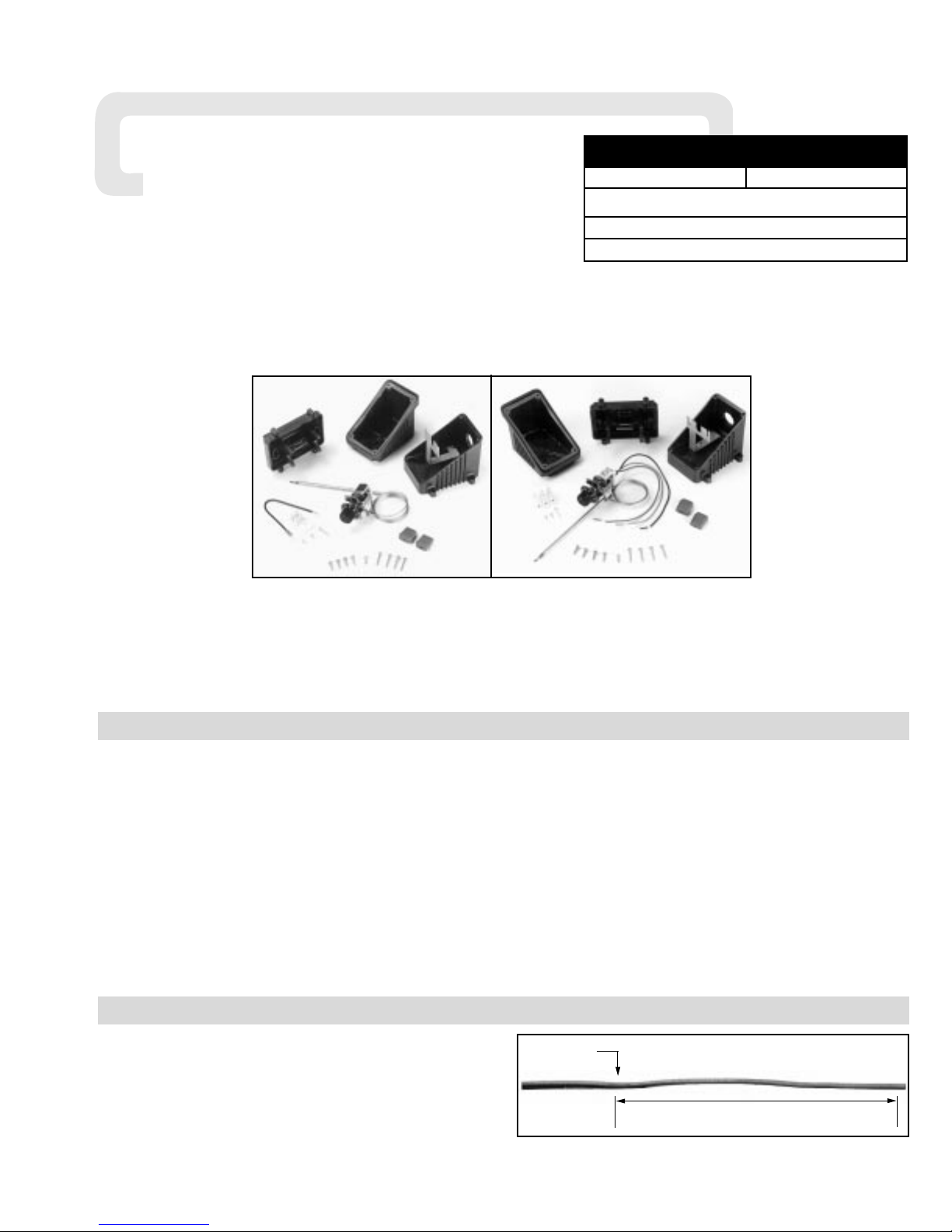
RTBC and R TBC-EP
Power Connection Kit With Integral Thermostat
INSTALLATION
Note: These instructions are for all Self-Regulating and Constant
Wattage Heating Cables in ordinary locations. Consult factory for
installation of braided cable in hazardous locations. Not all
instructions, however, are for all cases. Each step of the instructions will have a heading in boldface stating which type of cable
or connection each instruction is intended for.
1. FOR CONSTANT WATTAGE CABLE:
Cut the cable 12 inches past the last module point (indentation
in cable). Note: Cutting the cable between module points creates a non-heating cold lead. See Figure 1.
Figure 1
12”
Module Point
RTBC Kit Parts:
1 — Molded Enclosure consisting of Base — Box — Lid
1 — Three Position Terminal Block
1 — Mounting Screw for Terminal Block
1 — Uninsulated Barrel Connector (RTBC-EP Only)
1 — Eight Inch Length of 14AWG Insulated Wire with
Connector (RTBC Only)
1 — Ring Connector (RTBC Only)
1 — Thermostat with Mounting Screws (2)
1 — Capillary Grommet
1 — Cover Gasket
4 — Cover Screws, 5/8” Long
4 — Box Screws, 1” Long
NOTICE: These thermostats are designed for temperature control service only.
Because they may not fail safe, they should not be used for temperature limiting duty.
WARNING: Users should install adequate back-up controls and
safety devices with their electric heating equipment. Where the
consequences of failure may be severe, back-up controls are
essential. Although the safety of the installation is the responsibility of the user, Chromalox will be glad to make equipment
recommendations.
RTBC
RTBC-EP
http://www.chromalox.com
Page 2
INSTALLATION
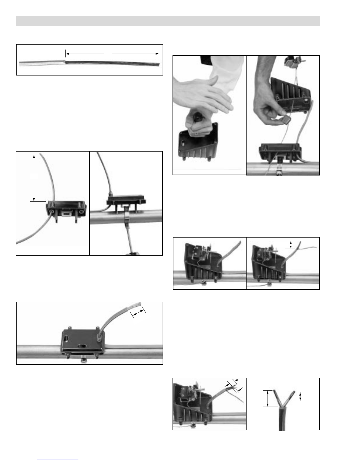
2. FOR CABLE WITH EXPOSED METAL BRAID (-C):
Push the braid back 12 inches on the cable. See Figure 2.
3. FOR ALL CABLE:
Feed the end of the cable through the appropriate hole in
the base. Allow 8 inches of cable to extend above the top of
the base. See Figure 3.
4. FOR ALL CABLE:
Slide cable grommet over the end of the cable and insert it into
the opening in the base. Attach the base to the pipe by threading
the appropriate sized pipestrap through the slot in the mounting
plate. Tighten the pipestrap until the base is loosely attached to
the pipe. See Figure 4.
5. FOR OVERCOATED CABLES (-CR or -CT):
Score the outer insulation 1-1/2 inches from the end of
the cable. Remove the jacket to expose the metal braid. See
Figure 5. WARNING: Do not damage the braid or the base
cable insulation.
6. FOR ALL CABLE:
Punch out the knockouts on the bottom of the box which correspond to the openings in the base through which the heating
cable passes. For these kits, the openings to be knocked out
are the ones opposite the conduit entry and the one by the side
of the box. Be careful to punch out only those knockouts to be
used. If one is mistakenly punched, blank grommets can be
ordered to re-establish the watertight seal. See Figure 6.
7. FOR ALL CABLE:
Feed the capillary of thermostat through the side hole of the box
and side hole of the base. Slip the grommet over the capillary
between the box and the base. See Figure 7.
8. FOR ALL CABLE:
Feed the cable through the end hole in the box. Allow 3/4 inches of stainless steel capillary to extend above the bottom of the
box. Secure box to base using all four large (8-32) screws. See
Figure 8.
9. FOR OVERCOATED CABLE:
Starting from the end of the cable. unravel 1-1/2 inches of the
braid. Twist the strands together to form a pigtail. See Figure 9.
10.FOR SELF-REGULATING CABLE:
Using standard electrical cutters, cut a 3/4 inch long notch out
of the cable between the conductor wires. Bare a 3/8 inch
length of each conductor by stripping off the outside insulation and the inner black core material. See Figure 10.
11.FOR CONSTANT WATTAGE CABLE:
Score the outer jacket 3/4 inch from the end of the cable and
remove the jacket. Cut off the exposed nichrome wire, pushing
any remainder back under the jacket. Constant Wattage cables
have an inner layer of insulation which is also to be removed
as described above. Separate the buss wires and strip off the
last 3/8 inch of insulation from both buss wires. See Figure 11.
Figure 2
12”
Figure 3
Figure 4
Figure 5
1-1/2”
8”
Figure 6
Figure 7
Figure 8
Figure 9
1-1/2”
Figure 10
Figure 11
1-1/2”
3/4”
3/8”
3/4”
http://www.chromalox.com
Page 3

12.FOR OVERCOATED CABLE (RTBC ONLY):
Insert the end of the braid pigtail into the opening in the terminal
block which will be nearest the center of the box. Tighten the
screw firmly to hold the braid in place. See Figure 12.
13.FOR ALL CABLE:
Insert the bared ends of the conductors into two adjacent
openings in the terminal block. Tighten screws firmly to hold
conductors in place. See Figure 13.
14.FOR RTBC ONLY:
Remove the screw and collar from the NORMALLY
CLOSED terminal of the thermostat. Discard the collar. Push
the screw through the opening in the connector attached to the
insulated wire and screw it back into the normally closed terminal. See Figure 14.
15.FOR ALL CABLE:
Connect conduit hub (Chromalox CCH-1 or equal) to the box.
Attach conduit to hub and bring 8 inches of power leads into
the box. See Figure 15.
16.FOR ALL CABLE:
Strip a 3/8 inch length of each conductor of the power wiring.
See Figure 16.
17.FOR RTBC ONLY:
Crimp the ring connector onto the end of the “HOT” conductor. Remove the screw and collar from the COMMON terminal. Discard the collar. Push the screw through the opening in
the ring connector. Drive the screw back into the COMMON
terminal. See Figure 17.
18.FOR RTBC ONLY:
Insert the bared end of the ground wire into the opening of the
terminal block which is opposite of the braid (or is empty).
Insert the ends of the other hot (or neutral) and the 8 inch long
wire into the two remaining openings in the terminal block.
Tighten screws firmly to hold conductors in place. See Figure
18.
19.FOR RTBC-EP ONLY:
Slide the bared end of the hot power lead into the opening in the
terminal block which is opposite of the empty terminal. Slide the
bared end of the other hot or the neutral power lead into the mid-
dle opening of the terminal block. Tighten the screws firmly to
hold the wires in place. See Figure 19.
20.FOR RTBC-EP ONLY:
A. Slide the bared end of the black (NORMALLY CLOSED)
thermostat wire into the opening of the terminal block which
is next to the incoming power leads.
B. Slide the bared end of the purple (COMMON) thermostat
wire into the opening opposite of the hot power lead.
Tighten the screws firmly to hold the wires in place. See
Figures 20A and 20B.
INSTALLATION
Figure 12
Figure 13
Figure 14
Figure 15
Figure 16
Figure 17
Figure 18
Figure 19
Figure 20A
Figure 20B
http://www.chromalox.com
Page 4

98 - 083
TA - X8 - 5K
Litho in U.S.A.
Chromalox
®
P R O D U C T S E R V I C E
600 RIDGELY ROAD, MURFREESBORO, TN 37129
PHONE: (615) 848-2565 FAX: (615) 848-2181
Chromalox warrants only that the Products and parts manufactured by Chromalox, when shipped, and
the work performed by Chromalox when performed, will meet all applicable specification and other specific
product and work requirements (including those of performance), if any, and will be free from defects in
material and workmanship under normal conditions of use. All claims for defective or nonconforming
(both hereinafter called defective) Products, parts or work under this warranty must be made in writing
immediately upon discovery, and in any event, within one (1) year from delivery, provided, however all
claims for defective Products and parts must be made in writing no later than eighteen (18) months after
shipment by Chromalox. Defective and nonconforming items must be held for Chromalox's inspections
and returned to the original f.o.b. point upon request. THE FOREGOING IS EXPRESSLY IN LIEU OF ALL
OTHER WARRANTIES WHATSOEVER, EXPRESS, IMPLIED AND STATUTORY, INCLUDING, WITHOUT
LIMITATION, THE IMPLIED WARRANTIES OF MERCHANTABILITY AND FITNESS FOR A PARTICULAR
PURPOSE.
Notwithstanding the provisions of this WARRANTY AND LIMITATION Clause, it is specifically understood that Products and parts not manufactured and work not performed by Chromalox are warranted only
to the extent and in the manner that the same are warranted to Chromalox by Chromalox's vendors, and
then only to the extent that Chromalox is reasonably able to enforce such warranty, it being understood
Chromalox shall have no obligation to initiate litigation unless Buyer undertakes to pay all cost and expens-
es therefor, including but not limited to attorney's fees, and indemnifies Chromalox against any liability to
Chromalox's vendors arising out of such litigation.
Upon Buyer's submission of a claim as provided above and its substantiation, Chromalox shall at its
option either (i) repair or replace its Products, parts or work at the original f.o.b. point of delivery or (ii)
refund an equitable portion of the purchase price.
THE FOREGOING IS CHROMALOX'S ONLY OBLIGATION AND BUYER'S EXCLUSIVE REMEDY FOR
BREACH OF WARRANTY, AND IS BUYER'S EXCLUSIVE REMEDY AGAINST CHROMALOX FOR ALL
CLAIMS ARISING HEREUNDER OR RELATING HERETO WHETHER SUCH CLAIMS ARE BASED ON
BREACH OF CONTRACT, TORT (INCLUDING NEGLIGENCE AND STRICT LIABILITY) OR OTHER THEORIES,
BUYER'S FAILURE TO SUBMIT A CLAIM AS PROVIDED ABOVE SHALL SPECIFICALLY WAIVE ALL
CLAIMS FOR DAMAGES OR OTHER RELIEF, INCLUDING BUT NOT LIMITED TO CLAIMS BASED ON
LATENT DEFECTS. IN NO EVENT SHALL BUYER BE ENTITLED TO INCIDENTAL OR CONSEQUENTIAL
DAMAGES AND BUYER SHALL HOLD CHROMALOX HARMLESS THEREFROM. ANY ACTION BY BUYER
ARISING HEREUNDER OR RELATING HERETO, WHETHER BASED ON BREACH OF CONTRACT, TORT
(INCLUDING NEGLIGENCE AND STRICT LIABILITY) OR OTHER THEORIES, MUST BE COMMENCED
WITHIN ONE (1) YEAR AFTER THE DATE OF SHIPMENT OR IT SHALL BE BARRED.
W2008M
WARRANTY AND LIMITATION OF REMEDY AND LIABILITY
21.FOR RTBC-EP ONLY:
Trim the blue (NORMALLY OPEN) thermostat wire so that it
is only 2 inches long. Tape over the end of the wire using
fiberglass tape. See Figure 21.
22.FOR RTBC-EP WITH OVERCOATED CABLE ONLY:
Slide the bared end of the ground wire into the end of the
uninsulated barrel connector. Crimp it on using a crimping
tool. Slide the end of the braid pigtail into the other end of the
uninsulated barrel connector and crimp it on. See Figure 22.
23.FOR ALL CABLE:
Mount terminal block to bottom of the box by driving the 6-32
self-tapping screw into the mounting hole as shown. See
Figure 23.
24.FOR ALL CABLE:
Thread the screws into the outside pair of mounting holes of
the thermostat leaving approximately 1/8 inch of thread. Slide
the screws into the slots in the mounting bracket. Push the
thermostat down as far as it will go and tighten the screws
firmly. See Figure 24.
25.FOR ALL CABLE:
Push the knob onto the shaft of the thermostat. Adjust thermostat to desired temperature setting. See Figure 25.
26.FOR ALL CABLE:
Carefully push wires into the box. Secure lid to box. See
Figure 26.
27.FOR CABLE WITH EXPOSED METAL BRAID:
Unravel four inches of braid from the cable and twist into a pigtail. Connect to appropriate grounding source. See Figure 27.
28.FOR ALL CABLE:
Extend capillary to allow bulb to be placed in desired location.
The bulb should be placed on the bottom half of the pipe
spaced 90˚ from the nearest heating cable or centered between
equally spaced heaters. Do not locate the bulb within 3feet of
a pipe support or other heat sink.
INSTALLATION
Figure 21
Figure 22
Figure 23
Figure 24
Figure 25
Figure 26
Figure 27
6-32 Screw
http://www.chromalox.com
 Loading...