

Page 1
PJ453-7
161-562764-001
JUNE, 2004
4RT
Installation Instructions
(Supersedes PJ453-6)
NOTICE: These thermostats are designed for temperature control service only.
Because they may not fail safe, they should not be used for temperature limiting duty.
WARNING: Users should install adequate back-up controls and
safety devices with their electric heating equipment. Where the
consequences of failure may be severe, back-up controls are
essential. Although the safety of the installation is the responsibility of the user, Chromalox will be glad to make equipment recommendations.
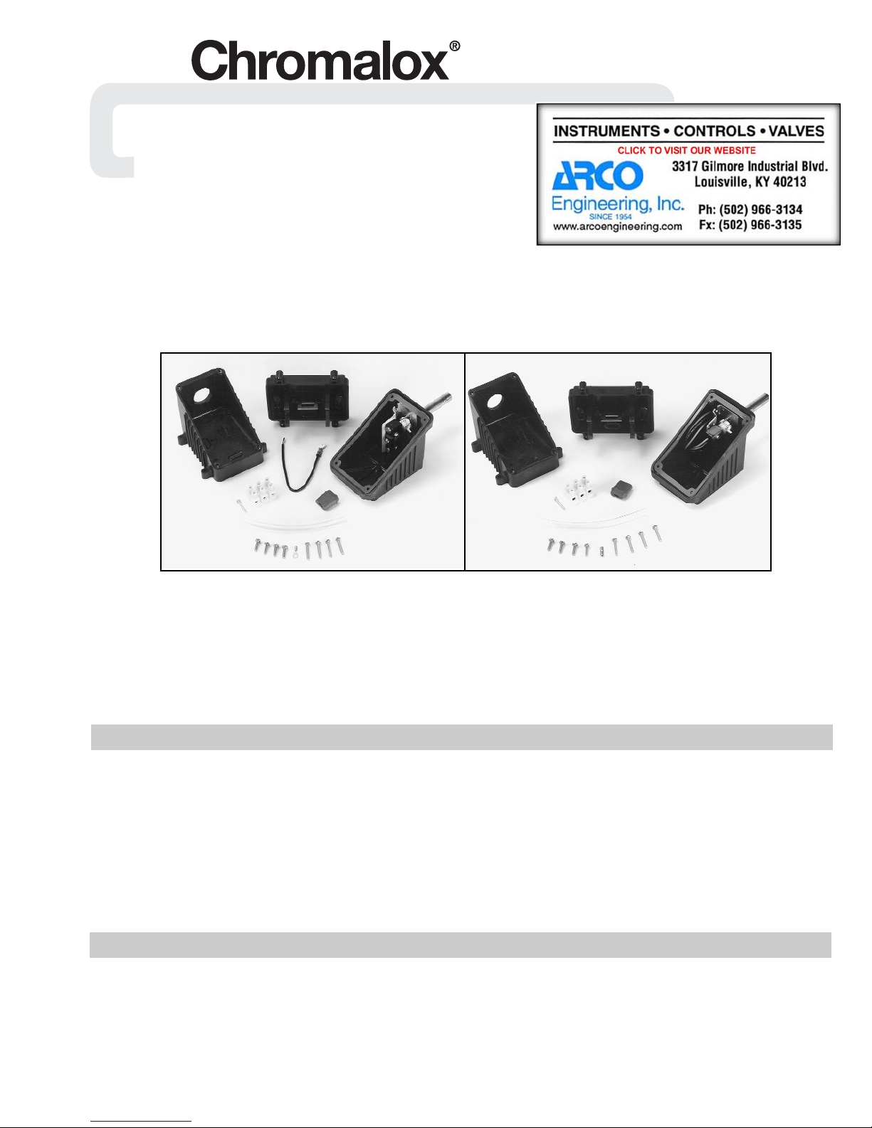
RTAS and RTAS-EP
Power Connection Kit With Integral Thermostat
RTAS
RTAS and RTAS-EP Kit Parts:
1 – Molded Enclosure consisting of Base – Box – Lid
1 – Three Position Terminal Block
1 – Mounting Screw for Terminal Block
1 – Uninsulated Barrel Connector (RTAS-EP Only)
1 – Cover Gasket
1 – Six Inch Length of Insulating Tubing
These kits are designed to provide temperature control as well
as termination for one run of Rapid Trace Heating Cable. Select
and purchase one grommet for terminating the cable. Please refer
to the list below to ensure you purchase the proper grommet for
the cable you are installing.
GR1 For SRL-C
GR2 For SRL-CR or SRL-CT
GR3 For CWM-C
GR4 For CWM-CT
GR5 For SRL-MC
GR6 For SRL-MCR or SRL-MCT
WARNING: Hazard of Electric Shock. Disconnect all
power before starting. All installations must be
effectively grounded in accordance with the
National Electrical Code to eliminate shock hazard.
Note: All electrical wiring, including GFCI (Ground Fault Circuit
Interrupters), must be done according to National Electrical or
local codes by a qualified person.
© 2010 Chromalox, Inc.
RTAS-EP
1 – Eight Inch Length of 14 AWG Insulated Wire
4 – Cover Screws, 5/8” Long
4 – Box Screws, 1” Long
1 – Ring Connector (RTAS Only)
1 – Thermostat
GENERAL
GR7 For SRM/E-C
GR8 For SRM-E/CT
Each kit contains enough material to connect one cable. One
additional self-regulating cable can be connected; an extra grommet is required.
Materials required for installation include: sharp utility knife,
standard electrical cutters, screwdriver and a pipe strap
(Chromalox PS or equal).
Wipe inside lip of cover with a clean cloth. Remove protective
backing from the gasket and affix it to the cover lip. Press firmly
all around for proper adhesion.
INSTALLATION
Note: These instructions are for all Self-Regulating and Constant
Wattage Heating Cables in ordinary locations. Consult factory for
installation of braided cable in hazardous locations. Not all
instructions, however, are for all cases. Each step of the instructions will have a heading in boldface stating what type of cable or
connection each instruction is intended.
Page 2
INSTALLATION
1. FOR CONSTANT WATTAGE CABLES:
Cut the cable 12 inches past the last module point (indention in
cable). Note: Cutting the cable between module points creates
a non-heating cold lead. See Figure 1.
Module Point
12”
Figure 1
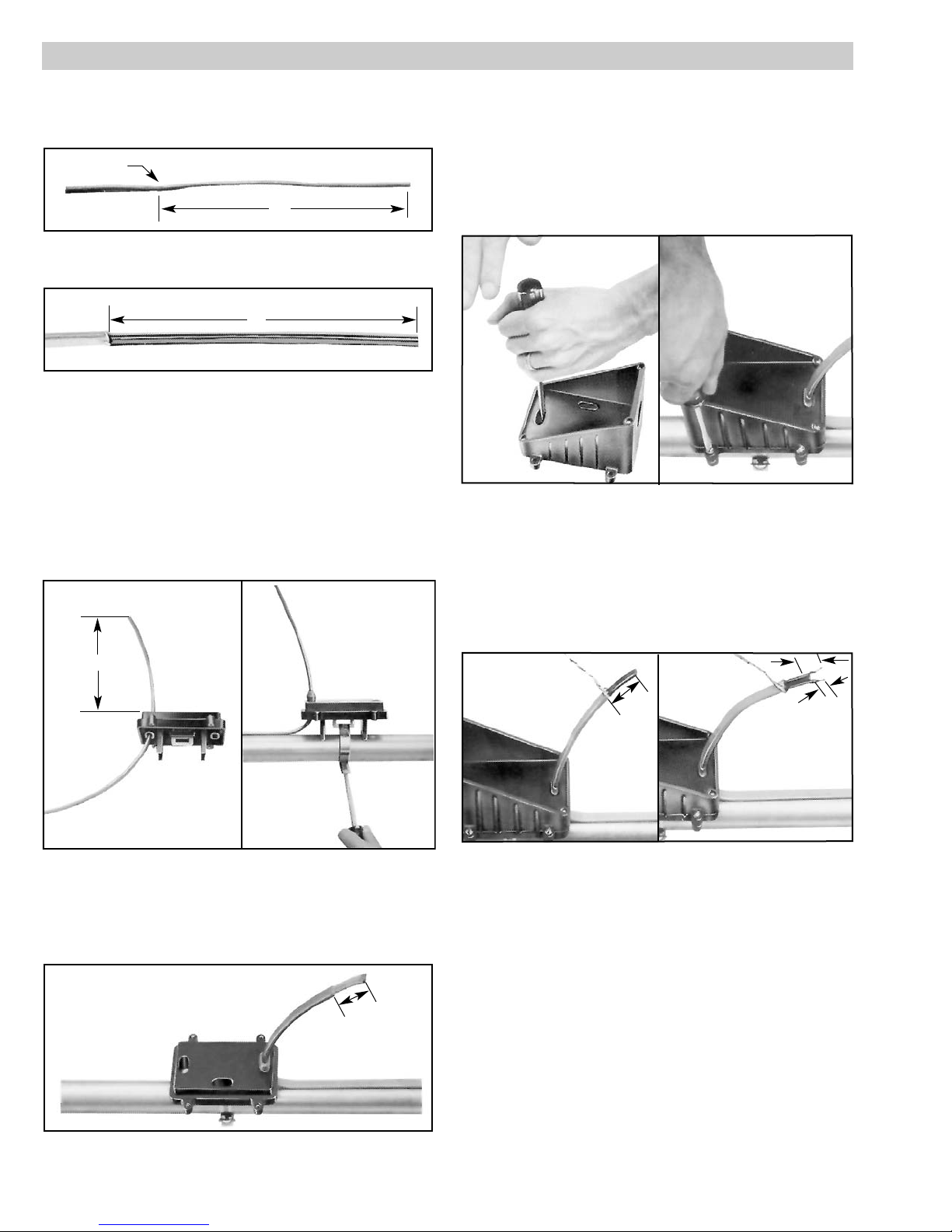
2. FOR CABLE WITH EXPOSED METAL BRAID (-C):
Push the braid back 12 inches on the cable. See Figure 2.
12”
Figure 2
3. FOR ALL CABLES:
Feed the ends of the cables through the appropriate holes in the
base. Allow eight inches of cable to extend above the top of the
base. Slide cable grommet over the end of the cable and insert
it into the opening in the base. See Figure 3.
4. FOR ALL CABLES:
Secure the base to the pipe by threading the appropriate sized
pipestrap through the slot in the mounting plate. Tighten the
pipestrap until the base is securely attached to the pipe. Slide
cable grommet over the end of the cable and insert it into the
opening in the base. See Figure 4.
6. FOR ALL CABLES:
Punch out the knockouts on the bottom of the box which correspond to the openings in the base through which the heating
cable passes. If you should make a mistake, blank grommets
can be ordered to re-establish the water tight seal. See Figure 6.
7. FOR ALL CABLES:
Feed the cables through the corresponding holes in the box.
Secure box to base using all four large (8-32) screws. See
Figure 7.
Figure 6 Figure 7
8. FOR OVERCOATED CABLES:
Starting from the end of the cable, unravel 1-1/2 inches of the
braid. Twist the strands together to form a pigtail. See Figure 8.
9. FOR SELF-REGULATING CABLES:
Using standard electrical cutters, cut a 3/4 inch long notch out
of the cable between the conductor wires. Bare a 3/8 inch
length of each conductor by stripping off the outside insulation
and the inner black core material. See Figure 9.
8”
Figure 3 Figure 4
5. FOR OVERCOATED CABLES (-CR or -CT):
Score the outer insulation 1-1/2 inches from the end of the cable.
Remove the jacket to expose the metal braid. See Figure 5.
WARNING: Do not damage the braid or the base cable insulation.
1-1/2”
3/4”
1-1/2”
Figure 8 Figure 9
10. FOR CONSTANT WATTAGE CABLES:
Score the outer jacket 3/4 inch from the end of the cable and
remove the jacket. Cut off the exposed nichrome wire, pushing
any remainder back under the jacket. Constant Wattage cables
have an inner layer of insulation which is also to be removed as
described above. Separate the buss wires and strip off the last
3/8 inch of insulation from both buss wires. See Figure 10.
11. FOR OVERCOATED CABLES:
Slide the insulating tube over the end of the cable. Insert the
end of the braid pigtail into the opening in the terminal block
which will be nearest the center of the box. Tighten the screw
firmly to hold the braid in place. See Figure 11.
3/8”
Figure 5
Page 3

INSTALLATION
3/4”
3/8”
Figure 10 Figure 11
12. FOR ALL CABLES:
Insert the bared ends of the conductors into two adjacent openings in the terminal block. Tighten screws firmly to hold conductors in place. See Figure 12.
3/8”
Figure 15 Figure 16
17. FOR RTAS ONLY:
Insert the bared end of the ground wire into the opening of the
terminal block which is opposite of the braid (or is empty).
Insert the ends of the other hot (or neutral) and the eight inch
long wire into the two remaining openings in the terminal
block. Tighten screws firmly to hold conductors in place. See
Figure 17.
Ground Wire
Figure 12
13. FOR RTAS ONLY:
Remove the screw and collar from the NORMALLY CLOSED
terminal of the thermostat. Discard the collar. Push the screw
through the opening in the connector attached to the insulated
wire and screw it back into the normally closed terminal. See
Figure 13.
14. FOR ALL CABLES:
Connect conduit hub (Chromalox CCH-1 or equal) to the box.
Attach conduit to hub and bring eight inches of power leads
into the box. See Figure 14.
Figure 13 Figure 14
15. FOR ALL CABLES:
Strip a 3/8 inch length of each conductor of the power wiring.
Crimp the ring connector onto the end of the “Hot” conductor.
See Figure 15.
16. FOR RTAS ONLY:
Remove the screw and collar from the COMMON terminal.
Discard the collar. Push the screw through the opening in the
ring connector. Drive the screw back into the COMMON terminal. See Figure 16.
Figure 17
18. FOR RTAS-EP ONLY:
Slide the bared end of the hot power lead into the opening in
the terminal block which is opposite of the empty terminal.
Slide the bared end of the other hot or the neutral power lead
into the middle opening of the terminal block. Tighten the
screws firmly to hold the wires in place. See Figure 18.
Figure 18
19. FOR RTAS-EP ONLY:
A. Slide the bared end of the black (NORMALLY CLOSED) ther-
mostat wire into the opening of the terminal block which is
next to the incoming power leads.
B. Slide the bared end of the purple (COMMON) thermostat wire
into the opening opposite of the hot power lead. Tighten the
screws firmly to hold the wires in place. See Figures 19A and 19B.
Page 4

INSTALLATION
Figure 19A Figure 19B
20. FOR RTAS-EP ONLY:
Trim the blue (NORMALLY OPEN) thermostat wire so that it
is only two inches long. Tape over the end of the wire using
fiberglass tape.) See Figure 20.
22. FOR ALL CABLES:
Mount terminal block to bottom of the box by driving the 6-32
self-tapping screw into the mounting hole as shown. See
Figure 22.
#6-32
Screw
Figure 22
23. FOR ALL CABLES:
The thermostat is shipped factory preset and pre-calibrated for
40°F operation. The setting may be changed by rotating the
white knobs until the desired temperature is directly behind the
setting post.
Carefully push the wires into the box. Secure lid to box. See
Figure 23.
Figure 20
21. FOR RTAS-EP WITH OVERCOATED CABLES ONLY:
Slide the bared end of the ground wire into the end of the uninsulated barrel connector. Crimp it on using a crimping tool.
Slide the end of the braid pigtail into the other end of the uninsulated barrel connector and crimp it on. See Figure 21.
Figure 21
Figure 23
24. FOR CABLES WITH EXPOSED METAL BRAID:
Unravel four inches of braid from the cable and twist into a
pigtail. Insert the end of the pigtail into one end of the uninsulated barrel connector and crimp it on. Connect to appropriate
grounding source.
Please refer to the Chromalox limited warranty applicable to this product at
http://www.chromalox.com/customer-service/policies/termsofsale.aspx.
Limited Warranty:
1347 HEIL QUAKER BLVD., LAVERGNE, TN 37086
Phone: (615) 793-3900 www.chromalox.com
 Loading...