

Page 1
(Supersedes PK413-3)
PK413-4
AR
161-562791-001
SEPTEMBER, 1995
4
and
Installation, Operation
RENEWAL PARTS IDENTIFICATION
Type AR-EP Industrial Explosion-Resistant
Thermostat
© 2010 Chromalox, Inc.
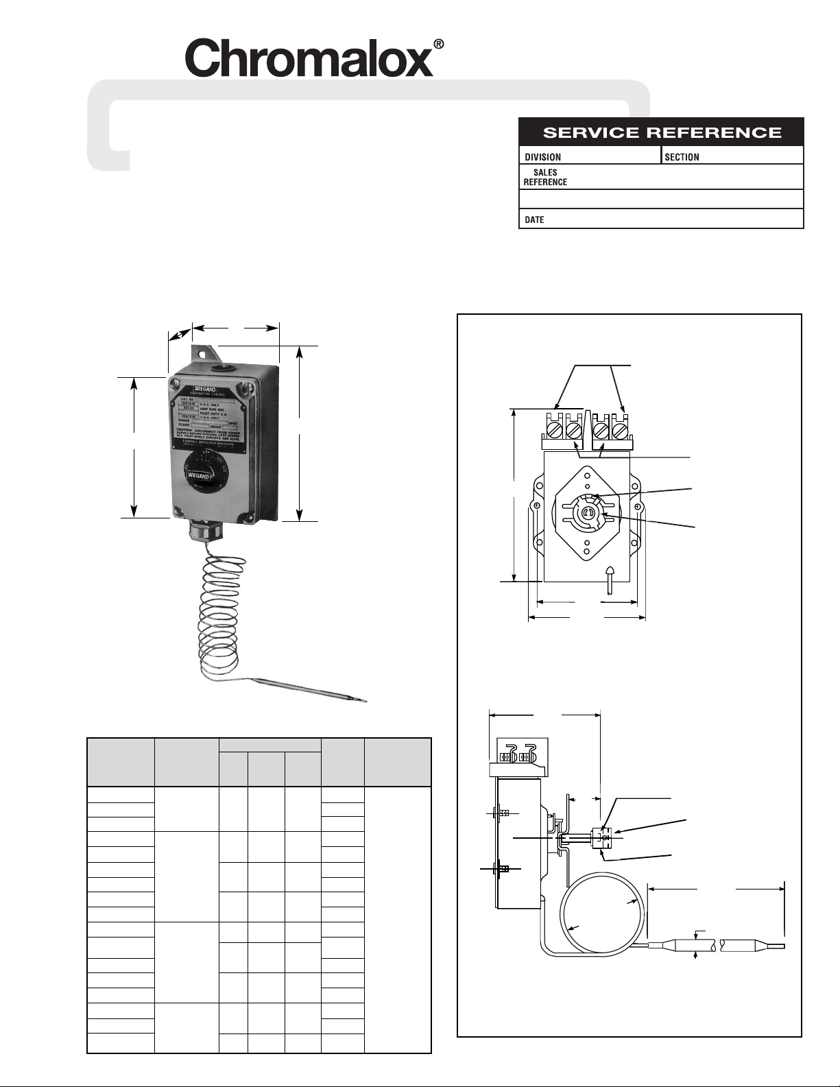
Specifications – Table A
2 / "
17
32
Length
(Refer to Specifications —
Table A)
2" O.D. Typ.
Capillary
2 / "
21
32
4 / "
3
32
2 / "
9
32
Dial
Stop
Post
Connect Load
Here
Shaft Shown
In "Off" Position
(Without Calibrated Cap)
Connect Power
Supply Here
/ "
11
16
Calibration Cap
White Nylon
Universal Coupler
Set Screw Lock
Figure 1
Sensing Bulb
Temperature Approx. Capillary Max.
Range Dia. Length Length A.C. Rating
Model (°F) Style (In.) (In.) (Ft.) (Amps)
AR-115EP 7
AR-115AEP 0 – 100 5 0.375 4
3
/8 2
AR-115CEP 12
AR-214EP 7
30 Amp
AR-214DEP
4 0.250 55/32
15 120-277 VAC
AR-215EP
60 – 250
7
AR-215AEP
5 0.375 4
2
AR-219EP 7
AR219DEP
9 0.188 10
3
/4
15 250 VA
AR-514EP 4 0.250 5
5
/8 7
120-277 VAC
AR-515EP 7
(Pilot Duty)
AR-515AEP
200 – 550 5 0.375 3
5
/8
2
AR-519EP
9 0.188 9
7
AR-519DEP 15
AR-715EP 5 0.375
3
11
/16
7
AR-715DEP 300 – 700 5 0.375 15
AR-719EP 9 0.188 12 7
61/2”
81/4”
4
1
/4”
4”
Page 2
GENERAL
NOTICE: Type AR-EP controls are designed for temperature control service only. Because they do not fail safe, they should not be
used for temperature limiting duty.
WARNING: Users should install adequate back-up
controls and safety devices with their electric
heating equipment. Where the consequences of
failure may be severe, back-up controls are essential. Although the safety of the installation is the
responsibility of the user, Chromalox will be glad to
make equipment recommendations.
Principle of Operation — Control action of these thermostats is
provided through the principle of liquid volume change. With a
variation in temperature, the liquid in the sensing bulb expands or
contracts, causing a bellows to actuate the switching mechanism.
Housing — The control housing and cover assembly is of heavyduty cast aluminum.
Control Range — The following temperature ranges are available:
Fahrenheit
0° to 100° 200° to 550°
60° to 250° 300° to 700°
Process Temperature Differential — is variation in controlled
process temperature between maximum, when thermostat turns
OFF and minimum, when thermostat turns ON. This spread in
temperature may be minimized by —
1. Making sure control is mounted to vertical surface. (See Step
1, MOUNTING section.)
2. Avoiding excess heating capacity (oversized heaters).
3. Locating control sensing bulb in optimum position between
heat source and work.
In general, it is difficult to predict the actual operating differential of a given process. Temperature differential may be as
low as 4°F for low range controls to as high as 17°F for higher range controls since the differential is a percentage function
of the dial range.
Packing Glands — If a sealed or leak-proof connection is required
at the point where the capillary enters the oven, tank, pipe or similar equipment, an appropriate packing gland is available as an
optional part. (Model CCF-25A, CCF-25D or CCF-25E)
WIRING
MOUNTING
WARNING: Hazard of Electric Shock. Disconnect all
power before wiring or servicing this control.
Failure to comply can result in electrical shock or
electrocution.
1. Electric wiring to heater must be installed in accordance with
National Electrical Codes and local codes. WARNING: Use
copper conductors only.
2. Entrance for wiring is provided by one
3
/4” NPT hole in the top
of the housing. Wiring to control housing must be in rigid conduit also in accordance with National Electrical Codes (NEC)
for hazardous locations.
3. Set thermostat knob to OFF position and remove cover plate by
loosening and removing four (4) fastening screws (see Figure 5).
Note: Do not mount thermostat where it will be subject to vibration, shock, grease, dust, lint or corrosive vapors. Do not mount
adjacent to a large magnetic contactor, as vibration and shock will
cause thermostat to interact erratically — resulting in chattering of
the contactor.
The air temperature in and around the thermostat enclosure
should be kept as near to normal room temperature as possible...
never above 150°F.
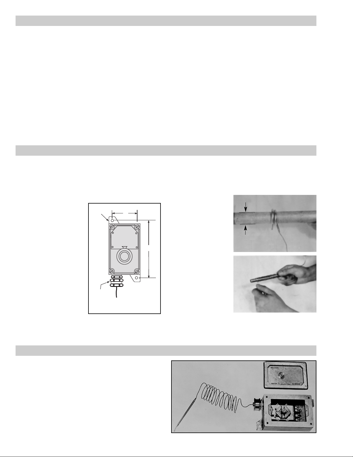
1. Thermostat must be mount-
ed in a vertical position only.
2. Use sheet metal or wood
screws through the two
5
/16”
diameter mounting holes in
mounting lugs to mount
control (see Figure 2).
3. For controlling platen or die
temperatures, insert entire
sensing bulb into drilled holes
selected for snug slip fit.
The longer, more sensitive Style 9 bulbs should be
used for controlling air temperatures or pipe line heating.
4. NOTICE:
A. Bending or deforming
sensing bulb will alter
control calibration —
requiring recalibration after installation. See CALIBRATION section, page 3. If necessary, Style 9 bulbs can be
coiled to 1” I.D. (see Figure 3).
B. Do not kink capillary tube. The resulting constrictions in
fluid flow can destroy control function or broaden temperature differential. Minimum capillary tube bending diameter is
1
/2” I.D. (see Figure 4).
C. Any deformations of bulb or capillary that result in leakage
of fluid from control renders control inoperative.
D. Avoid passing control capillary tube through zones whose
temperature is in excess of controlled process temperature.
Erratic control or destruction of control function may result.
Lugs
Capillary
Seal
Fitting
3"
7 / "
3
8
Figure 2
Figure 3
(Sensing Bulb)
Figure 4
(Capillary Tube)
Figure 5
Do Not
Bend or Kink
Crimped End
1
/2”
Rod
1”
-2-
Page 3

1
2
3
4
1
2
3
4
Pilot
Light
Load
Line
Single Phase
Pilot Light
Load
Line
Single Phase
1
2
3
4
Pilot Light
Line
Load
Load
Two Circuit
4. Remove white shaft coupler for safe-keeping while making
wiring connections (see Figure 6).
5. Connect wires according to wiring diagrams (Figures 7 thru 11).
Note: Electrical connections should be made with generous
loops of wire — approximately 6” per lead.
6. Replace white shaft coupler.
7. WARNING: It is possible to replace enclosure
cover with adjustment knob 180 rotational
degrees out of alignment resulting in large calibration errors. To avoid this, carefully follow
these procedures.
A. Be sure that thermostat shaft is fully counter-clockwise (see
Figure 12). With thermostat knob held in the indicated OFF
position, carefully replace enclosure cover while feeling for
proper engagement of
shaft coupling.
B. With cover screws replaced
and moderately fastened,
check for full rotation of
dial knob. Note: Mild shaft
resistance should be
encountered. If satisfied,
that proper engagement of
shaft coupler is accomplished; finish tightening
cover screws.
8. Note: If load amperage or
voltage rating exceeds switch
rating, a contactor must be
used. Contactor and wiring to
be supplied by customer (see
-3-
WIRING
CALIBRATION
WARNING: Hazard of Electric Shock. Extreme care
should be exercised during calibration adjustments
because of shock hazard due to exposed electrical
terminals. Failure to comply can result in electrical
shock or electrocution.
These controls are factory calibrated to the range indicated on
the control adjustment knob.
If calibration is required, either one of two methods may be
followed.
1. If accurate measurement standards are not available, the thermostat can readily be adjusted to a known temperature standard
such as boiling water (212°). See Figure 13.
2. With the aid of an accurate thermometer or other temperature
measuring device, recalibration may be performed within the
process as in Figure 14.
For either method, the following general calibration procedures
should be followed.
Dial
Stop
Post
Stop
Tab
Figure 12
Figure 6
1
2
3
4
1
2
3
4
Pilot
Light
Line
Three Phase
when Load
Does Not
Exceed
Rating of
Thermostat
}
Three Phase
and Single
Phase when
Load Exceeds
Rating of
Thermostat
Control
Voltage
Line
Pilot
Light
Contactor
Figure 13
Figure 7
Figure 8 Figure 9
Figure 10 Figure 11
Page 4

CALIBRATION
THERMOSTAT SUB ASSEMBLY REPLACEMENT
DANGER: Calibration will involve exposure of inter-
nal control terminals to ambient conditions during
some part of the recalibration procedure.
Combustible materials which cause hazardous
conditions must not be present during recalibration process — otherwise explosion may result.
1. Heat water bath or the equipment in which the control is
installed (tank, die, platen or machine) to the selected calibration temperature. The entire sensing bulb and at least one foot
of its capillary tube are to be exposed to calibrating temperature. With thermostat energized, allow process or bath to reach
setpoint. This is accomplished when thermostat begins cycling
action.
2. Compare adjustment knob cut off temperature indication
against actual temperature to which sensing bulb is exposed.
Figure 15 shows example of a control knob showing a control
indication of 250°F when true process temperature measured
230°F. In this example, the control knob must be rotated 20°
counterclockwise to bring the 230°F knob marking under the
index mark in order to recalibrate the control.
3. Without disturbing the shaft setting, loosen the thermostat
knob set-screw and re-align dial setting accordingly. Retighten
knob set-screw.
4. Recheck for thermostat operation as per steps 2 and 3 and make
further calibration adjustment if indicated.
5. Recheck of thermostat operation following final adjustment
completes the calibration procedure.
IMPORTANT: Under no circumstances must the temperature
range, and in particular, the maximum temperature setting of control be increased above maximum temperature indicated on control
nameplate. Such changes voids U.L. listing of the control.
1. Before removing enclosure cover, turn thermostat knob to the
OFF position (counterclockwise). Place a piece of masking
tape over the knob to keep it in the OFF position.
2. Remove the enclosure cover by removing four fastening
screws (Figure 5).
3. Remove the white shaft coupler for safe-keeping.
4. Remove the thermostat mounting screws (2).
5. Loosen the capillary-seal retaining cap set screws and then
remove the retaining cap.
Note: Do not remove the entire capillary seal fitting from the
enclosure.
6. Remove the capillary seals and thermostat from the enclosure.
7. Remove the calibration cap (Figure 1) and insert pin from the
old thermostat. Rotate the position of the calibration cap, for
use in the next step.
8. With replacement thermostat in the OFF position (shaft complete-
ly counterclockwise), install insert pin and calibration cap. Install
calibration cap with same orientation as noted in step 7 above.
9. If excess capillary, on old thermostat, had been coiled in enclo-
sure, it may be necessary to coil an equal amount on replacement thermostat per step 4D mounting instructions.
10. After proper capillary length is obtained on replacement ther-
mostat, insert capillary in the enclosure and thru the capillary
seal fitting.
11. Recheck for proper capillary length (external to enclosure) and
adjust if necessary.
12. Align spacer plate and replacement thermostat to mounting
holes in the bottom of enclosure using mounting screws (2 –
#10-32 x
3
/8 Lg.) to secure thermostat to enclosure.
13. Slide the capillary seals into the capillary fitting making sure
the capillary is positioned in the center groove of the seals.
WARNING: If capillary is not located in the center groove properly, damage to the capillary will
result, rendering the thermostat inoperable or
unreliable.
14. Replace capillary seal retaining cap and tighten set screws to
lock in position.
Note: Per the NEC, all threaded connections in a hazardous
environment must be tightened sufficiently to engage five full
threads.
15. Rewire replacement thermostat per appropriate wiring dia-
grams (Figures 7 thru 11).
16. Replace the white nylon coupling on the calibration cap and
enclosure cover per step 7 of the wiring section.
17. Replacement thermostat control should be monitored to insure
proper operation. If calibration is required, see the calibration
section for instructions.
Thermometer
Load (Tank, vat, die or platen)
True Temp
250
200
A
Figure 14
Figure 15
-4-
Page 5

-5-
RENEWAL PARTS IDENTIFICATION
Thermostat
Model Sub Assembly Control Knob
AR-115EP 300-027566-001 169-019605-002
AR-115AEP 300-027566-014 169-019605-002
AR-115CEP 300-027566-012 169-019605-002
AR-214EP 300-027566-004 169-019604-001
AR-214DEP 300-027566-015 169-019604-001
AR-215EP 300-027566-009 169-019604-001
AR-215AEP 300-027566-007 169-019604-001
AR-219EP 300-027566-002 169-019604-001
AR-219DEP 300-027566-016 169-019604-001
AR-514EP 300-027566-005 169-019604-002
AR-515EP 300-027566-008 169-019604-002
AR-515AEP 300-027566-006 169-019604-002
AR-519EP 300-027566-003 169-019604-002
AR-519DEP 300-027566-018 169-019604-002
AR-715EP 300-027566-010 169-019605-001
AR-715DEP 300-027566-011 169-019605-001
AR-719EP 300-027566-013 169-019605-001
Parts Common to All
Part Part Number
Capillary Seal Fitting . . . . . . . . . . . . . . . . . . . . . . . . . . . . . . .119-053954-001
White Nylon Coupler . . . . . . . . . . . . . . . . . . . . . . . . . . . . . . .079-512424-001
Page 6

1347 HEIL QUAKER BLVD., LAVERGNE, TN 37086
Phone: (615) 793-3900 www.chromalox.com
Limited Warranty:
Please refer to the Chromalox limited warranty applicable to this product at
http://www.chromalox.com/customer-service/policies/termsofsale.aspx.
 Loading...