

Page 1
PK410-1
161-048634-001
JUNE, 1989
4WR
Installation Instructions
(Supersedes PK410)
Type WR Room Thermostat
© 2010 Chromalox, Inc.
Specifications – Table A
GENERAL
Positive accuracy, long and reliable service, 3° differential.
Heavy-duty, single stage, SPST line voltage snap-acting switch.
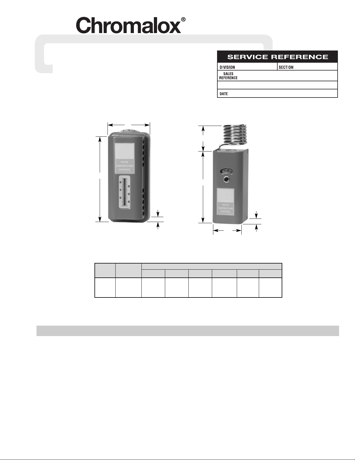
Patented hydraulic element. WR-80 has internal sensing element
and thermometer on cover; WR-90 has external, coiled sensing
element but no thermometer. Both have a low position which
drops control point to keep heater off. WR-80 and WR-90 finished in tough metallic gray with chrome trim; mounting plate
fits outlet or conduit box.
Uses – Automatically controls room temperature by turning electric air heaters on and off. Can be used to control the air heaters
directly, within thermostat rating. For higher ratings use thermostat with magnetic contactor. Place thermostat on inside wall,
away from undue heating or cooling influences, about 4 feet
above the floor. WR-90 is especially useful in holding lower temperatures, for example, in garages, warehouses, factories, etc.
NOTICE: Type WR thermostats are designed for temperature
control service only. Because they do not fail safe, they should
not be used for temperature limiting duty.
CAUTION: Users should install adequate back-up controls and
safety devices with their electric heating equipment. Where the
consequences of failure may be severe, back-up controls are
essential. Although the safety of the installation is the responsibility of the user, Chromalox will be glad to make equipment recommendations.
Principle of Operation – Control action of these thermostats is
provided through the principle of liquid volume change. With a
variation in temperature, the liquid in the sensing element
expands or contracts, causing a bellows to actuate the switching
mechanism.
CAUTION: Not for use in hazardous environments
as described in National Electrical Code. Failure to
comply can result in explosion or fire.
WR-80
40 to 80°F
UL Listed
Maximum Rating
Range
Model (°F) 120Vac † 115Vac 240Vac † 230Vac 277Vac 480Vac
WR-80 40-80 125va pilot 125va pilot 125va pilot
25 amps duty (use 22 amps duty (use 18 amps duty (use
WR-90 20-90 or 3000 with d-c or 5280 with d-c or 5000 with a-c
total watts contactor) total watts contactor) total watts contactor)
WR-90
20 to 90°F
UL Listed
† d-c ratings not UL listed
53/8”
21/2”
21/4”
2
9
/16”
6”
23/4”
2
1
/2”
Note —
WR-80 is
not a
Fail-Safe
Device.
Page 2
MOUNTING
Note: Do not mount control where it will be subject to vibration,
shock, grease, dust, lint or corrosive vapors. Do not mount adjacent to a large magnetic contactor, as vibration and shock will
cause thermostat to interact erratically – resulting in chattering of
the contactor.
CAUTION: Do not twist or uncoil the coiled element on top of the
case of the WR-90.
The proper location of a heavy duty room thermostat is important
to assure good performance.
1. Locate where air circulates freely.
2. Never install on or near outside wall.
3. Keep away from windows or doors.
4. Do not locate too close to strong light or other false source of
heat, such as sunlight, steam lines, etc.
5. If electrical conduit leads into cooler or warmer room, plug up
space around wires in the conduit with rock wool.
WIRING
CALIBRATION
CAUTION: Hazard of Electric Shock. Disconnect all
power before wiring or servicing this control.
1. Electric wiring to heater must be installed in accordance with
National Electrical Code and with local codes. WARNING:
Use copper conductors only.
Connect wires according to wiring diagrams (Figures 1 and 2).
Note: Electrical connections should be made with generous
loops of wire – approximately 6” per lead.
Note: If load amperage or voltage rating exceeds switch rating,
a contactor must be used. Contactor and wiring to be supplied
by customer. (See Figure 2)
CAUTION: Hazard of Electric Shock. Extreme care
should be exercised during calibration adjustments
because of shock hazard due to exposed electrical
terminals.
WR-80 thermostats are accurately calibrated at the factory so
the dial setting correctly indicates the temperature at which the
contacts open on temperature rise. If, as a result of damage in transit or for other reasons the room temperature differs appreciably
from the dial setting, the calibration may be adjusted as follows:
1. Note temperature on thermometer.
2. Set dial at highest temperature.
3. Turn dial slowly to lower temperature and stop when thermo-
stat contacts open.
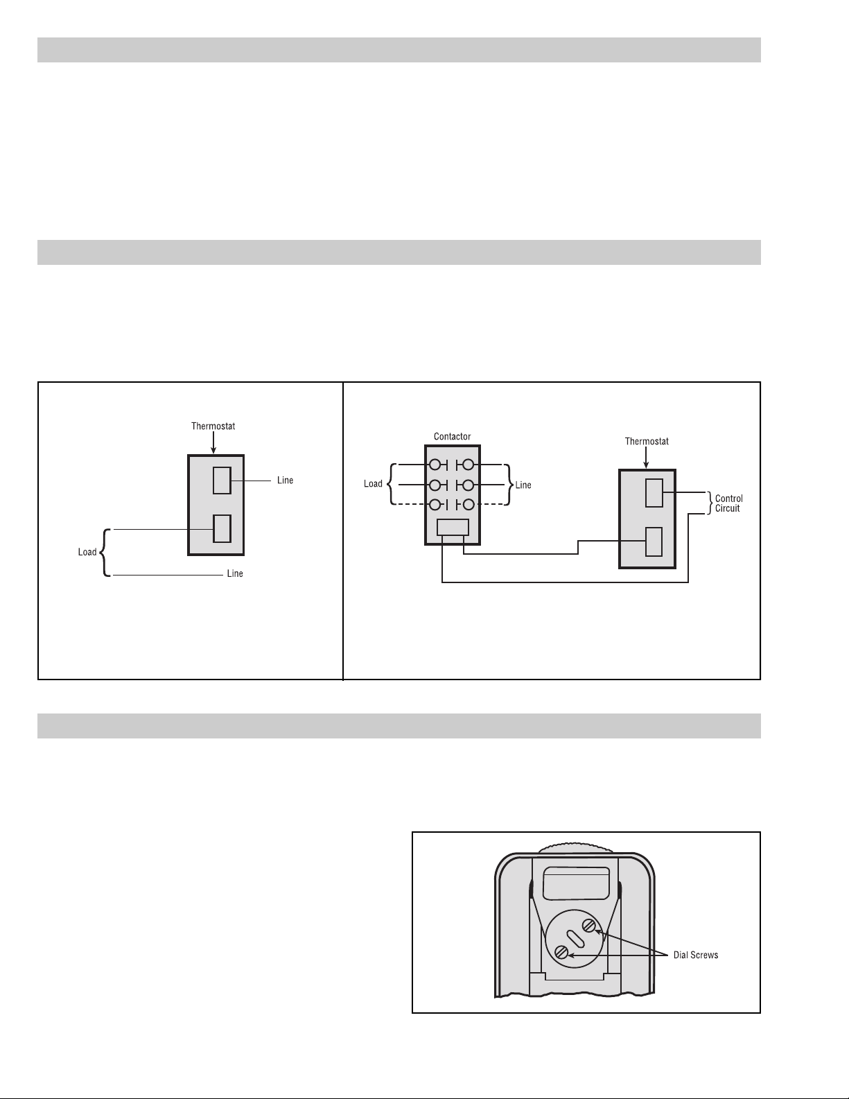
4. Loosen screw at bottom of thermostat and remove thermostat
from mounting plate.
5. On back of thermostat, loosen two dial screws (Figure 3).
Carefully turn the dial only to correct temperature setting as
indicated by thermometer. Be sure the thermostat shaft is not
moved during this operation.
6. Tighten the dial screws and replace thermostat.
Figure 3
Figure 1 — Single phase loads when load does not exceed
rating of thermostat.
Figure 2 — Single phase loads when load exceeds rating of thermostat and
three phase loads.
Page 3

SETTING
WR-90 controls have an adjustable differential. The movable
indicator points to the temperature at which the contacts open. The
fixed indicator points to the temperature at which the contacts close.
The difference between these two indicators is the differential.
To set the control, proceed as follows:
1. Use screwdriver in slot and turn the dial so the fixed indicator
“B” points to the temperature at which heating is to start.
2. Turn the differential adjusting screw “C” until the movable
indicator “D” points to the temperature at which the heating is
to stop.
UNITING LIQUID IN THERMOMETER
Sometimes the red liquid inside the thermometer on the WR80 becomes separated during shipment. The thermometer will not
read correctly when this red liquid is separated at any point. If the
red liquid in the thermometer of this thermostat has become separated it may be reunited as follows:
1. Remove the thermostat from the wall, and straighten out the
four prongs so the cover can be removed to expose the ball of
the thermometer.
2. Hold the lighted end of a cigarette or a match at such a distance
from the SIDE of the ball of the thermometer so the red liquid
rises SLOWLY in the stem of the thermometer.
3. When the lowest separation goes into the reservoir, immedi-
ately remove the heat and blow on the thermometer.
CAUTION: If there is more red liquid in the stem of the thermometer above the lowest separation than there is below it, it is
best to replace the thermometer.
CALIBRATION
Figure 4
Figure 5
Page 4

1347 HEIL QUAKER BLVD., LAVERGNE, TN 37086
Phone: (615) 793-3900 www.chromalox.com
Limited Warranty:
Please refer to the Chromalox limited warranty applicable to this product at
http://www.chromalox.com/customer-service/policies/termsofsale.aspx.
 Loading...