

Page 1
(Supersedes PG417-2)
PG417-3
SK
161-048460-001
OCTOBER, 2004
4
Type SKR Infrared Comfort Heater
© 2010 Chromalox, Inc.
Specifications – Table A
GENERAL
Chromalox Type SKR radiant heaters are designed for indoor
installation only, and are to be ceiling mounted with such spacing
between heaters to project heat radiation downwards to maintain
comfort level within the radiation field.
Before Installing
1. Open carton and remove heater at the place of installation.
Mounting clamps are in parts bag in carton.
2. Check nameplate volt and watt rating against your power supply voltage and heating requirements of your installation. This
nameplate is located on one end of the heater.
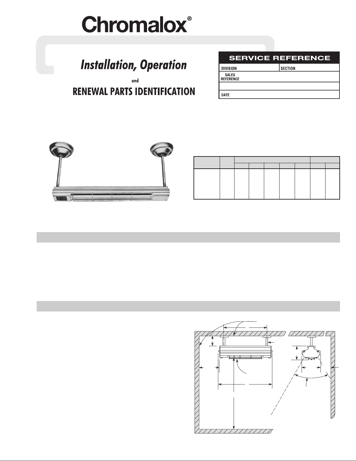
MOUNTING (See Figure 1)
1. Layout heater locations to the desired heat affected work area.
2. Minimum spacing to walls and ceiling are —
A. One foot (12”) from top of heater to ceiling.
B. Two feet (24”) from side or end of heater to adjacent walls.
3. Minimum safe height above floor level for combustible mater-
ial is 6 feet (72”). However, if ceiling height permits, more
practical height is 8 feet or more to avoid high radiation intensities at head level when one stands directly below heater.
INSTALLATION
Combustible Surfaces
Protective Grille
12” Min.
24”
Min.
24”
Min.
Maximum
Radiation
Within
60° Included
Angle
A
72” Min.
B
3-11/16”
2-3/4”
3/8” Conduit
Figure 1
Single Phase Power Circuit Amps Dimensions (In.)
Model Watts 120V 208V 240V 275V 480V A B
SKR-2083 0800 6.7 3.9 3.4 – – 243/8 227/8
SKR-3113 1100 9.2 5.3 4.6 – – 305/8 291/8
SKR-4183 1800 – 8.7 7.5 6.6 – 465/8 451/8
SKR-5253 2500 – 12.00 10.50 9.1 5.3 613/8 597/8
SKR-6303 3000 – 14.40 12.50 10.90 6.3 733/4 721/4
SKR-7363 3600 – 17.30 15.00 13.10 7.5 853/4 841/4
Page 2
INSTALLATION
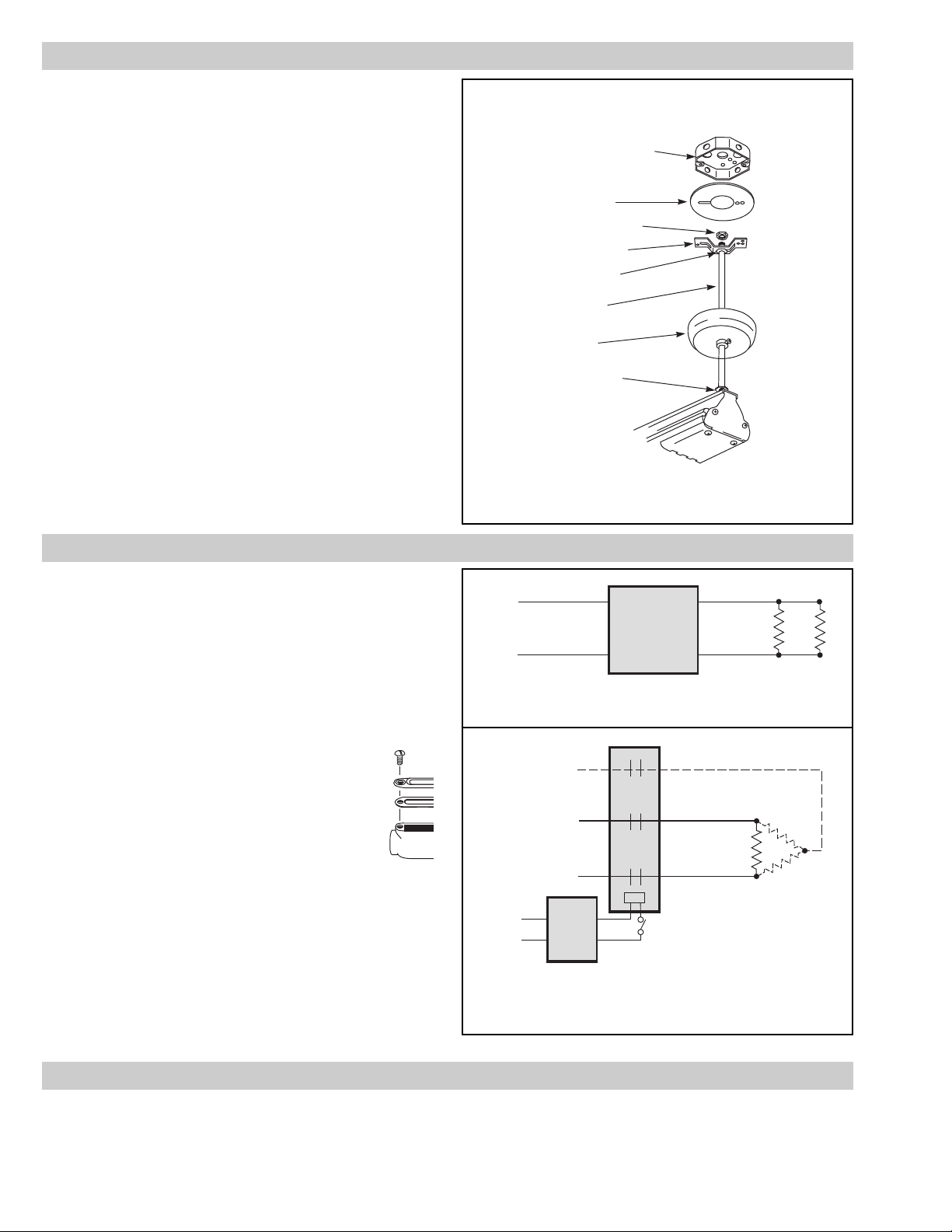
4. Refer to Figure 2. Assemble one flat lock nut onto one end of
each support tube or conduit and thread them into the tapped
openings in top of heater. One of these support tubes contains
three insulated wire leads. Handle with care to avoid damage
to lead insulation.
WARNING: Do not cut the support tube for in doing so the
minimum 12” clearance to ceiling will be violated resulting in
excessive ceiling temperatures. Tighten lock nut securely
against heater case.
5. Slip the canopies loosely over the fixture support tubes.
6. Assemble remaining locknuts onto ends of support conduits. Flat
nut goes on first; spherical nut last with its convex side facing
heater. See Figure 2. There should be full thread engagement at
the top spherical nut. Allow about
1
/2” spacing between nuts to
facilitate hanging to brackets. Set the assembly aside.
7. WARNING: Hazard of Electric Shock. Disconnect
all power to ceiling wiring box to which one
heater support will be fastened.
8. Install special cover plate and saddle bracket, provided with
heater, over ceiling wiring box after fishing insulated power
leads and ground lead, if provided, through large opening in
cover plate. Use mounting screws provided with wiring box.
9. Mount remaining saddle bracket to ceiling at the remaining
planned point of support. The brackets should be on B dimension centers given in Specifications — Table A.
10. Raise heater assembly, and slide both spherical nuts through
slot in saddle brackets until spherical nut rests in the slot
depressions. Run bottom lock nut up against bracket to lock
the assembly into place.
WIRING
OPERATION
WARNING: Hazard of Electric Shock. Any installa-
tion involving electric heaters must be grounded to
earth to eliminate shock hazard.
1. All wiring to heater wiring box shall be in accordance with
National Electrical Code and/or local wiring code.
2. Power conductors should be sized to handle 125% of heater
current given in Specifications — Table A.
3. Complete electrical wiring between heater leads and power
leads using insulated wire nuts. Tuck excess lead around and
behind saddle brackets.
4. The green colored ground lead should be
connected to ground lead from wiring box,
or if such lead is not provided, then the
ground lead should be grounded to the conduit box to insure ground continuity. Note:
If heaters are to be suspended more than 12”
below ceiling, the heater support tubes
should terminate into a Crouse-Hinds Type
C Condulet in line wiring box where splice
to power leads can be made (See Figure 3).
A
3
/8” pipe or conduit extension of the
desired length from top of Condulet can
then terminate at the ceiling wiring box utilizing cover plate, brackets, and lock nuts as
with conventional installation.
5. To complete installation raise canopies to completely enclose
brackets and electrical wiring. Tighten set screw.
6. If wiring from heater becomes damaged or requires replacement, it should be replaced with special high temperature wire
as furnished with heater. Replacement wires can be ordered
from Chromalox. (See RENEWAL PARTS section.)
DANGER: Fire Hazard. This heater is not intended
for use in hazardous atmospheres where flammable vapors, gases, liquids or other combustible
atmospheres are present as defined in the National
Electrical Code. Failure to comply can result in
explosion or fire.
1. Although most heaters operate at full capacity, it is possible to
reduce heating capacity with an Input Controller (Chromalox
Type VC or VCR — check factory) which can be manually set to
turn on heaters from 4% to 100% of a 15 or 30 second operating
cycle, providing, in effect, infinite control of heater output. Refer
to Figures 4 and 5 as may be appropriate to your installation.
Maximum number of Heaters limited by 25 AMP. — 120 Volt, 20 AMP. —
240 Volt Controller Rating.
The VC or
VCR
15 or 30
Second
Input
Controller
120 or
240V
SKR
Heaters
Wired 1ø
Contactor
SKR Heaters
Wired 1ø or 3ø
120, 208, 240, 275,
480 Volt Single
or Three Phase
Limiting Thermostat (Optional)
Input
Control
120 or
240V
Single Phase Wiring — Solid Line
Three Phase Wiring — Dotted Added
(Type VC or VCR) when voltage and load current exceed controller capacity
{
{
SKR Radiant Heater Control by Input Controller
Figure 4
Figure 5
Figure 3
Cover Plate
Spherical Locknut
Saddle Bracket
Flat Locknut
Canopy
Flat Locknut
3-1/1/4or 4" octagonal
box to be installed in
ceiling at one end of
heater location. (Customer furnished).
3/8” Stem
Figure 2
Page 3

WARNING: Hazard of Electric Shock. Disconnect all
power before servicing heater.
TO REMOVE HEATING ELEMENT
1. Remove terminal cover screws and terminal cover.
2. Disconnect heating element from electrical leads at both ends.
3. Remove screws from porcelain terminal blocks.
4. Remove element support clips and secondary insulating bush-
ings (where used).
5. Lift out element.
TO INSTALL ELEMENT
Observe instructions for removing element and proceed in
reverse fashion. Be sure to replace secondary insulating bushings
and support clips (where used).
WARNING: For your own safety —
Before energizing this heater:
1. Be sure all electrical connections are tightly made. Hold termi-
nal with pliers when tightening screw.
2. Be sure that all conductors are properly insulated.
3. Be sure that all element assemblies have been properly
replaced, and that secondary insulation bushings and support
clips (where used) have not been omitted.
CARE OF REFLECTORS
Reflectors should be cleaned periodically. A mild soap and
water solution or fine cleaning powder is best although more drastic means may be required if reflectors are badly soiled by chemical or other deposits. The reflector is aluminum. DO NOT use
alkali cleaners since alkalies will dull reflector. Mild non-alkaline
cleaners, such as used for scouring kitchen sinks, amy be used.
Reflectors are replaceable and may be purchased from Chromalox.
MAINTENANCE
RENEWAL PARTS IDENTIFICATION
24
25
23
26
25
15
20
15
18
19
PARTS COMMON TO ALL HEATERS
10 Terminal Cover . . . . . . . . . . . . . . . .306-014405-001 (2)
11 Terminal Cover Clip . . . . . . . . . . . .056-014401-002 (4)
12 End Plates . . . . . . . . . . . . . . . . . . .220-014462-004†
220-014462-002
13 Terminal Screw . . . . . . . . . . . . . . .248-002793-001 (2)
14 Saddle Clamp . . . . . . . . . . . . . . . . .238-026539-001 (2)
MISCELLANEOUS HARDWARE
15 #8 x 1” Lg. . . . . . . . . . . . . . . . . . . .248-075519-095 (6)
16 #8 x
3
/8” Lg. . . . . . . . . . . . . . . . . . .248-075519-080 (4)
17 #8-32 x
3
/8” Lg. . . . . . . . . . . . . . . . .248-075414-051 (4)
MISCELLANEOUS PARTS
18 Terminal Block . . . . . . . . . . . . . . . .303-016367-001 (2)
19 Speed Nuts . . . . . . . . . . . . . . . . . .272-048153-005 (4)
20 Terminal Block . . . . . . . . . . . . . . . .303-014326-001 (2)
21 Conduit . . . . . . . . . . . . . . . . . . . . .069-017920-001 (2)
22 Cover Plate, Box . . . . . . . . . . . . . . .220-017915-001 (1)
TERMINAL BLOCK SET
168-016585-001 consists of the following:
18
Terminal Block . . . . . . . . . . . . . . . .303-016367-001 (2)
19 Speed Nuts . . . . . . . . . . . . . . . . . .272-048153-005 (4)
20 Terminal Block . . . . . . . . . . . . . . . .303-014326-001 (2)
15 Screws — #8 x 1” Lg. . . . . . . . . . .248-075519-095 (6)
HANGER KIT
168-050202-001 (2) consists of the following:
23
Canopy, with set screw . . . . . . . . . . . . . . . . (1)
24 Hanger Bracket . . . . . . . . . . . . . . . . . . . . . . (1)
25 Flat Locknut . . . . . . . . . . . . . . . . . . . . . . . . (2)
26 Hex Nut (Spherical) . . . . . . . . . . . . . . . . . . . (1)
† Indicates stamped end plate with voltage, wattage, etc.
Note: Part numbers suffixed by a number in ( ) indicates the quantity of the same part number used.
Figure 6
Figure 7
Figure 8
Figure 9
Page 4

2150 N. RULON WHITE BLVD., OGDEN, UT 84404
Phone: 1-800-368-2493 www.chromalox.com
RENEWAL PARTS IDENTIFICATION
12 78 9
Heating Aluminum 3 4 5 6 Green Element Support Insulation
Model Volts kW Element Housing Reflector Grille Short Lead Long Lead Ground Wire Clip Bushing
SKR-2083 120 0.8 RTU-2083AV 152-017859-001 234-013411-011 134-017852-001 (0) 175-048142-041 175-048142-042 175-048142-224
SKR-2083 208 0.8 RTU-2083AV 152-017859-001 234-013411-011 134-017852-001 (0) 175-048142-041 175-048142-042 175-048142-224
SKR-2083 240 0.8 RTU-2083AV 152-017859-001 234-013411-011 134-017852-001 (0) 175-048142-041 175-048142-042 175-048142-224
SKR-3113 120 1.1 RTU-3113AV 152-017859-002 234-013411-012 134-017852-002 (0) 175-048142-041 175-048142-043 175-048142-224
SKR-3113 208 1.1 RTU-3113AV 152-017859-002 234-013411-012 134-017852-002 (0) 175-048142-041 175-048142-043 175-048142-224
SKR-3113 240 1.1 RTU-3113AV 152-017859-002 234-013411-012 134-017852-002 (0) 175-048142-041 175-048142-043 175-048142-224
SKR-4183 208 1.8 RTU-4183AV 152-017859-003 234-013411-014 134-017852-003 (0) 175-048142-041 175-048142-044 175-048142-224 059-013424-001 (1) 032-013454-001 (2)
SKR-4183 240 1.8 RTU-4183AV 152-017859-003 234-013411-014 134-017852-003 (0) 175-048142-041 175-048142-044 175-048142-224 059-013424-001 (1) 032-013454-001 (2)
SKR-4183 275 1.8 RTU-4183AV 152-017859-003 234-013411-014 134-017852-003 (0) 175-048142-041 175-048142-044 175-048142-224 059-013424-001 (1) 032-013454-001 (2)
SKR-5253 208 2.5 RTU-5253AV 152-017859-004 234-013411-016 134-017852-004 (0) 175-048142-041 175-048142-045 175-048142-224 059-013424-001 (2) 032-013454-001 (4)
SKR-5253 240 2.5 RTU-5253AV 152-017859-004 234-013411-016 134-017852-004 (0) 175-048142-041 175-048142-045 175-048142-224 059-013424-001 (2) 032-013454-001 (4)
SKR-5253 275 2.5 RTU-5253AV 152-017859-004 234-013411-016 134-017852-004 (0) 175-048142-041 175-048142-045 175-048142-224 059-013424-001 (2) 032-013454-001 (4)
SKR-5253 480 2.5 RTU-5253MI 152-017859-004 234-013411-016 134-017852-004 (0) 175-048143-022 175-048143-024 175-048142-224 059-013424-001 (2) 032-013454-001 (4)
SKR-6303 208 3.0 RTU-6303AV 152-017859-005 234-013411-018 134-017852-005 (0) 175-048142-041 175-048142-046 175-048142-224 059-013424-001 (3) 032-013454-001 (6)
SKR-6303 240 3.0 RTU-6303AV 152-017859-005 234-013411-018 134-017852-005 (0) 175-048142-041 175-048142-046 175-048142-224 059-013424-001 (3) 032-013454-001 (6)
SKR-6303 275 3.0 RTU-6303AV 152-017859-005 234-013411-018 134-017852-005 (0) 175-048142-041 175-048142-046 175-048142-224 059-013424-001 (3) 032-013454-001 (6)
SKR-6303 480 3.0 RTU-6303MI 152-017859-005 234-013411-018 134-017852-005 (0) 175-048143-022 175-048143-025 175-048142-224 059-013424-001 (3) 032-013454-001 (6)
SKR-7363 208 3.6 RTU-7363AV 152-017859-006 234-013411-038 134-017852-003 (2) 175-048142-041 175-048142-047 175-048142-224 059-013424-001 (4) 032-013454-001 (8)
SKR-7363 240 3.6 RTU-7363AV 152-017859-006 234-013411-038 134-017852-003 (2) 175-048142-041 175-048142-047 175-048142-224 059-013424-001 (4) 032-013454-001 (8)
SKR-7363 275 3.6 RTU-7363AV 152-017859-006 234-013411-038 134-017852-003 (2) 175-048142-041 175-048142-047 175-048142-224 059-013424-001 (4) 032-013454-001 (8)
SKR-
7363 480 3.6 RTU-7363MI 152-017859-006 234-013411-038 134-017852-003 (2) 175-048143-022 175-048143-026 175-048142-224 059-013424-001 (4) 032-013454-001 (8)
Note: Part numbers suffixed by a number in ( ) indicates the quantity of the same part number used.
Limited Warranty:
Please refer to the Chromalox limited warranty applicable to this product at
http://www.chromalox.com/customer-service/policies/termsofsale.aspx.
 Loading...