

Page 1
Chromalox
®
DIVISION 4 SECTION
RBC
SALES
REFERENCE
DATE
SERVICE REFERENCE
Installation Operation
and
RENEWAL PARTS IDENTIFICATION
PG416-4
161-025617-001
MARCH,1999
(Supersedes PG416-3)
© 2010 Chromalox, Inc.
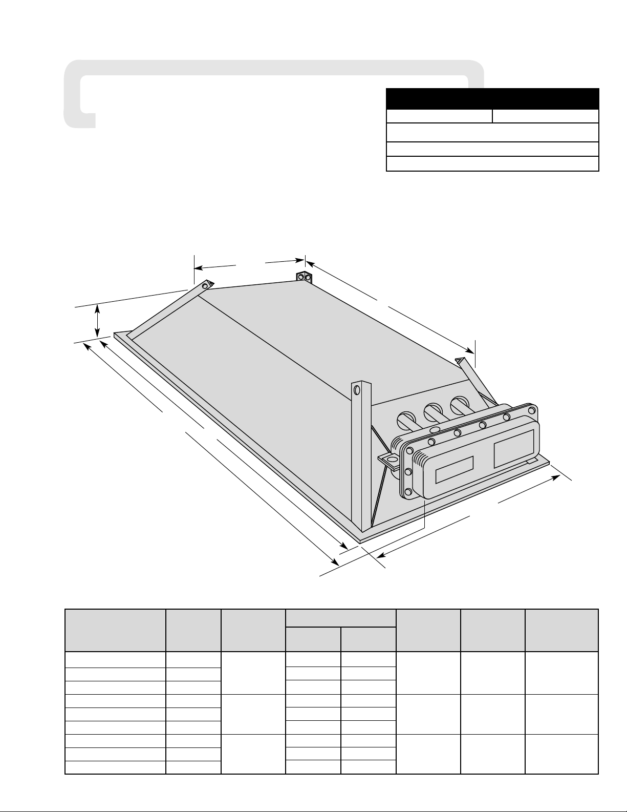
Type RBC-3 Radiant Heater
Amperage Net
No.
Weight
Model Volts kW
1 Phase 3 Phase
BTU
Elements
(Lbs.)
RBC-31280 208 5.8 ——
RBC-31220 240 1,200 5.0 —— 4,094 1 8
RBC-31240 480 2.5 ——
RBC-32480 208 11.5 ——
RBC-32420 240 2,400 10.0 —— 8,188 2 8-3/4
RBC-32440 480 5.0 ——
RBC-33680 208 17.3 10.0
RBC-33620 240 3,600 15.0 8.7 12,272 3 9-3/4
RBC-33640 480 7.5 4.3
17-5/8”
29”
32-3/4”
5-1/2”
10-1/2”
22”
Page 2

GENERAL
The Chromalox Type RBC-3 Radiant Heater is designed primarily as an indoor comfort heater to be used where supplemental heat is
needed or for spot heating in unheated areas and damp locations.
Its aluminum construction and consequent light weight make it
ideal for suspension with the No. 2 size chain and “S” hooks provided. Aluminum reflector housing requires no painting and is easily cleaned.
WARNING: Users should install adequate controls
and safety devices with their electric heating
equipment. Where the consequences of failure may
be severe, back-up controls are essential.
Although the safety of the installation is the
responsibility of the user, Chromalox will be glad to
assist in making equipment recommendations.
WIRING
WARNING: Hazard of Electric Shock. Any installation
involving electric heaters must be effectively
grounded in accordance with the National Electrical
Code to eliminate shock hazard.
Electric wiring to heater must be installed in accordance with
the National Electrical Code and with local codes by a qualified
person. WARNING: Use copper conductors only.
WARNING: To prevent electrical wiring problems
due to overheating, route wiring conduit to avoid
contact with reflector housing.
MOUNTING
WARNING: Hazard of Electric Shock. Disconnect all
power before installing heater.
Minimum mounting distances for all heaters are as shown in
Figures A and B. Using the No. 2 size chain and “S” hooks furnished, heaters are to be suspended in a horizontal position only.
NOTE: For proper balance, it is suggested that each of the four
corners be individually suspended (rather than gathered into a
common center mounting point, see Figure C and D).
Model 208V 240V 480V 208V 240V 480V
Fig. Fig. Fig. Fig. Fig. Fig.
RBC-31280 1 —— —— —— —— ——
RBC-31220 —— 1 —— —— —— ——
RBC-31240 —— —— 1 —— —— ——
RBC-32480 2 —— —— —— —— ——
RBC-32420 —— 2 —— —— —— ——
RBC-32440 —— —— 2 —— —— ——
RBC-33680 3 —— —— 4 —— ——
RBC-33620 —— 3 —— —— 4 ——
RBC-33640 —— —— 3 —— —— 4
Table B — Wiring Diagram
Figure A
Figure B
Figure D (Wrong Way)Figure C (Right Way)
4" Min.
72" Min.
14"
Min.
Ceiling
Wall
Floor
Wall
Wall
14"
Min.
9" Min.
Conduit
Furnished by
Installer
1 Phase
3 Phase
Page 3

WIRING DIAGRAMS
OPERATION
WARNING: This heater is not intended for use in
hazardous atmospheres where flammable vapors,
gases, liquids or other combustible atmospheres
are present as defined in the National Electrical
Code. Failure to comply can result in explosion or
fire.
1. Minimum spacing from front of heater case to combustible
material is: 4 ft. — RBC3-12 (1200W)
7 ft. — RBC3-24 or RBC3-36 (2400W or 3600W)
2. Avoid temperatures in excess of 194˚F on nearby combustible
surfaces.
3. Do not operate heaters at voltages in excess of that stamped
on heater nameplate since excess voltage will shorten heater life.
4. CONTROLLING RADIANT INTENSITY —
When it is desirable to reduce radiant intensity, Input
Controllers may be used. These motor-driven cycling devices
can be used to vary heater output capacity from 4% to 100%.
Cycling devices are usually connected in holding coil circuit of
magnetic contactors. For further information regarding Input
Controllers and Contactors, see Chromalox catalog and/or contact your local Chromalox representative.
5. WARNING: Because of the possibility of someone
unknowingly exposing the heater to combustible
hazards, the heater should not be left in operation
while unattended.
MAINTENANCE
WARNING: Hazard of Severe Shock. Disconnect all
power to heater before servicing these heaters.
A. Element Replacement (See Figure E)
1. Remove Terminal housing cover and gasket.
2. Disconnect element leads from external leads.
3. Loosen and disengage hex nut and washer from threaded fitting.
4. Pull element out of reflector housing and terminal box.
5. Slide new gasket (see Renewal Parts) onto threaded fitting of
replacement element. Note: Filler side of gasket faces away
from flange of threaded fitting. Insert new element through terminal box opening, and slip on washer and hex nut before element enters reflector housing. Tighten hex nut until element
mounting is secure.
6. Reconnect power supply leads to element terminals. Install
new terminal cover gasket (see Renewal Parts). Install terminal
box cover. Reconnect power to heater circuit.
B. Care of Reflector
The reflectors should be kept clean to obtain the maximum
radiant output. The entire assembly should be washed or brushed
off periodically to remove dust and dirt. However, if the inside of
the reflector gets badly soiled, a mild soap and water solution may
be used. Wipe reflecting surface dry to prevent permanent water
marks. For extreme cases of soil which do not yield to mild soap
cleaning, use plastic or fine steel wool type scouring pads commonly used on cooking utensils. Avoid use of ammonia or alkaline cleaners which will etch the aluminum surfaces.
Note: Avoid hosing down the heater assembly because conduit may not be waterproof.
Figure 1
Figure 2
Figure 4
Figure E
L1
L2
Ground (Green)
G
Ground (Green)
G
L1
L2
Ground (Green)
G
L3
L1
L2
Figure 3
For supply connections use wire suitable for at least 90˚C (see below)
For supply connection use 14GA. min. wire suitable for at least 75˚C.
For supply connection use 14GA. min. wire suitable for at least 90˚C.
Ground (Green)
G
L1
L2
For supply connection use 14GA. min. wire suitable for at least 90˚C.
208V 10GA. min.
240V 12GA. min.
480V 14GA. min.
Terminal Box
Hex Nut
Washer
Compression
Gasket
Grounding
Terminal
Threaded
Fitting
Page 4

2150 N. RULON WHITE BLVD., OGDEN, UT 84404
Phone: 1-800-368-2493 www.chromalox.com
RENEWAL PARTS IDENTIFICATION
Common Parts
Heating Element Gasket Terminal Cover Gasket
132-047675-004 132-012603-004
Heating Element Part No. Volts kW
322-874016-003 208 1.2
322-874016-001 240 1.2
322-874016-002 480 1.2
Limited Warranty:
Please refer to the Chromalox limited warranty applicable to this product at
http://www.chromalox.com/customer-service/policies/termsofsale.aspx.
 Loading...