

Page 1
(Supersedes PG412-9)
PG412-10
RADD
161-026681-001
DECEMBER, 2008
4
RENEWAL PARTS IDENTIFICATION
Installation, Operation
and
DATE
SALES
REFERENCE
DIVISION SECTION
Chromalox
®
© 2010 Chromalox, Inc.
Type RADD Electric
Radiant Heaters
Specifications
The Safety Alert Symbol is used to indicate a risk of personal injury.
Please familiarize yourself with these instructions before
attempting to install or operate this Radiant Heater.
Before Installing:
1. Open carton and remove heater at the place of installation.
Mounting clamps are in parts bag in carton.
2. Check nameplate volt and watt rating against your power sup-
ply voltage and heating requirements of your installation. This
nameplate is located on one end of the heater.
The system designer is responsible for the safety
of this equipment and should install adequate
back-up controls and safety devices with their
electric heating equipment. Where the consequences of failure could result in personal injury or
property damage, back-up controls are essential.
INSTALLATION
ELECTRIC SHOCK HAZARD. Disconnect all power
before installing or servicing heater. Failure to do
so could result in personal injury or property damage. Heater must be installed or serviced by a
qualified person in accordance with the National
Electrical Code, NFPA 70.
1. These radiant heaters are designed for indoor installation only.
2. Mounting Clamps — Mount heaters by using the mounting
clamp and 3/8” bolt assembly.
Clamp assembly may be attached to heater by sliding over end
or by snapping over top of extruded frame section at any point
along its length. (see Fig. 2) For proper heater support, the
maximum distance between clamps must not exceed 48”. On
extra-long heaters, more than two clamps are furnished.
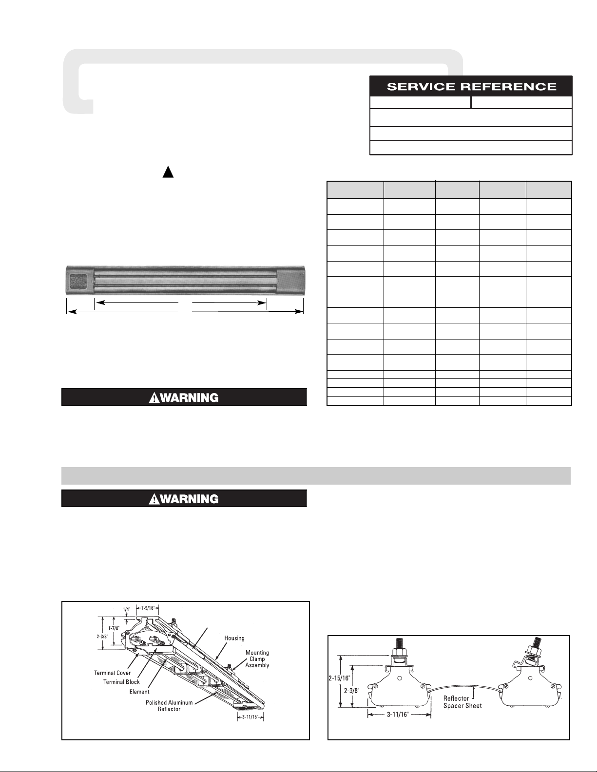
3. Mounting Holes — When heaters are mounted adjacent to
each other in the same plane, note that distance between
mounting holes on framing to support heaters will be 3-11/16”
minimum. When heaters are not in the same plane, i.e., set at
an angle to one another, distance between mounting holes in
framing will be either greater or less than 3-11/16”.
4. Framing — Where an extensive installation is being made, the
use of continuous slot metal framing manufactured by several
concerns will be of assistance in saving time and money. The
framing is reusable.
(Interlocking Connectors
Discontinued)
AB
Model No. Volts kW Overall Length Heated Length
RADD-2164 120 or 240
1.6 24-3/8 16-1/2
RADD-2164V 208 or 275
RADD-3224 120 or 240
2.2 30-5/8 22-3/4
RADD-3224V 208 or 275
RADD-3264V 208 or 275
2.6 35-7/8 28-5/16
RADD-3264 240 or 480
RADD-4364V 208 or 275
3.6 46-5/8 38-1/2
RADD-4364 240 or 480
RADD-5434V 208 or 275
4.3 53-7/8 45-7/16
RADD-5434 240 or 480
RADD-5504V 208 or 275
5.0 61-3/8 53-3/8
RADD-5504 240 or 480
RADD-6544V 208 or 275
5.4 65-7/8 58-1/4
RADD-6544 240 or 480
RADD-6604V 208 or 275
6.0 73-3/4 65-3/4
RADD-6604 240 or 480
RADD-7674V 208 or 275
6.7 79-7/8 72-1/4
RADD-7674 240 or 480
RADD-7724V 208 or 275
7.2 85-3/4 78
RADD-7724 240 or 480
RADD-8904V 208 or 275
9.0 106 97-1/2
RADD-8904 240 or 480
RADD-7604X10 240 or 480 8.0 114-1/8 106
RADD-7604X13 240 or 480 10 141 132
RADD-7604X9A 240 or 480 11 160-5/8 150
RADD-7724X38 240 or 480 13 185-5/8 174
B
A
Figure 1 — Heater Parts and Dimensions
Figure 2
!
Page 2
-2-
INSTALLATION (cont’d.)
ELECTRIC SHOCK HAZARD. Disconnect all power
before installing or servicing heater. Failure to do
so could result in personal injury or property damage. Heater must be installed or serviced by a
qualified person in accordance with the National
Electrical Code, NFPA 70.
ELECTRIC SHOCK HAZARD. Any installation
involving electric heaters must be performed by a
qualified person and must be effectively grounded
in accordance with the National Electrical Code to
eliminate shock hazard.
1. Electrical connection to the Radiant Heater is made through
two openings tapped for 1/2” connector. Openings are in the
top of the extruded heater housing, one near each end.
2. Access to Radiant Heater terminals is obtained by removing
the two screws in each of the terminal box covers.
3. Wiring should be run in flexible or rigid metal conduit and
must be installed in accordance with the requirements of the
National Electric Code and such other local requirements as
may be applicable.
4. Wires supplying power to heating element terminals shall have
insulation rated for 150°C minimum.
High Temperatures will oxidize copper. Use only nickelplated copper wire for supplying power to heater. Do not
use aluminum conductors.
5. A sufficient length of high temperature wire (not less than 12”
should extend from heater terminals to a remote connection
box whose location involves normal room temperatures thereby permitting use of normal electrical wiring to that point.
6. Leave loop of wire in heater terminal box to allow for expan-
sion movement of heating elements.
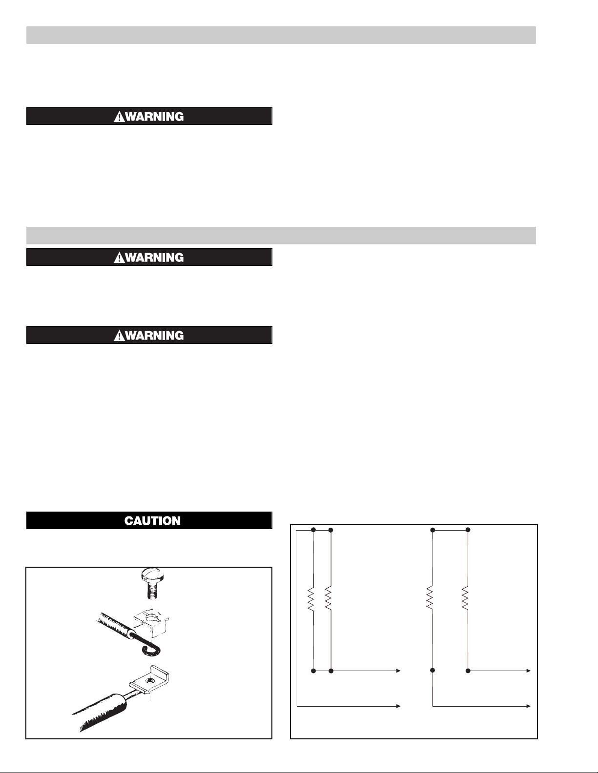
7. Assemble terminal, screw, saddle clamp and wire as shown in
Figure 3.
8. Hold terminal with pliers and tighten the terminal screw
securely with a screwdriver.
9. Single End. Parallel Wiring (Fig. 4A) Power wiring enters
heater through either of the 1/2” tapped openings in heater
housing. Wiring to opposite end is conveyed through wire-way
provided behind integral reflector in housing extrusion. High
temperature wire must be used; maximum wire diameter (over
insulation) must not exceed 0.224”. Each element must be
rated at applied line voltage.
10. Single End, Series Wiring (Fig. 4B) Power wiring enters
heater through either of the 1/2” tapped openings in heater
housing. Heating element terminals at opposite end are wired
in series. High temperature wiring must be used. Each element
must be rated at 1/2 line voltage.
External series wiring of radiant heater assemblies is not practical when internal series connections can be made so easily.
WIRING
Single End — Parallel
Figure 4A
Single End — Series
Figure 4B
Figure 3
5. Reflector Spacer Sheets —
Where heaters are not mounted side
by side (see Fig. 2), reflector spacer sheets can be used between
heaters. These reflector spacer sheets and companion reflectors
consisting of an extruded aluminum housing with reflector sheet
and mounting clamps are available. Check factory.
FIRE HAZARD: Since Radiant heaters are capable
of developing high temperatures, extreme care
should be taken to:
A. Keep combustible materials at least 6” away
form sides and back of heater housing and its
supporting brackets and spaced far enough in
front of heater (heating element side) so thermal
radiation from the elements will not ignite combustible materials.
B. If combustible materials are being processed,
stoppage of process should initiate immediate
heater shutdown and interception of residual
heat from radiant heaters (use radiation baffles
or move heaters away from work).
C. In the case of solvents of an explosive nature,
ventilation air must be in sufficient volume to
dilute the solvent vapor so that explosive mixtures cannot occur, refer to NFPA 86, Standard
for Ovens and Furnaces.
Page 3

11. Delta Connections — When heaters occur in multiples of
three, they may be connected to, and balanced across, threephase lines. The most commonly used connection is the delta
connection illustrated in Fig. 5. Three phase Delta connections
to minimize inductive effect in conduits are made per this diagram. The rule: run all 3 three-phase conductors in the same
conduit as far as possible. For single-phase, run only two conductors and follow the same rule.
-3-
OPERATION
FIRE/EXPOSION HAZARD. This heater is not
intended for use in hazardous atmospheres where
flammable vapors, gases, liquids or other combustible atmospheres are present as defined in the
National Electrical Code.Failure to comply can
result in personal injury or property damage.
Before energizing this heater:
1. Be sure all electrical connections are tightly made. Hold ter-
minal with pliers when tightening screw.
2. Be sure that all conductors are properly insulated.
3. Be sure that all element assemblies have been properly
replaced, and that secondary insulation bushings have not been
omitted.
A. Controlling Radiant Intensity
Standard Radiant heaters are built to operate at 40 watts per sq.
inch on the element sheath. When it is desired to reduce radiant
intensity, one or more of the following methods may be used.
1. INPUT CONTROLLERS. These motor-driven cycling
devices can be used to vary heater output capacity from 4 to
100%. They are usually connected in holding coil circuit of
controlling magnetic contactors. See Chromalox Radiant
Heater Manual for further information regarding Input
Controllers and Contactors.
2. SOLID STATE THYRISTOR POWER CONTROLLERS.
For best non-contact control of radiant heat, a Series #6
Chromalox Thyristor Power Controller with manual potentiometer setting is recommended. Truly proportional output of
from 0 — 100% can be easily dialed-in to suit the particular
product or process requirements. The Series #6 panels are preengineered, pre-packaged assemblies in an enclosure with circuit disconnect provided and ready for installation.
B. Maximum Ambient Temperatures
Chromalox Radiant Heaters are not recommended for applications in ambient temperatures exceeding 450°F. Higher ambient temperatures mean shorter heater life.
Maximum work temperature in a given time depends on several factors: Reflectivity of work, specific heat of work, mass of
work, kW input and losses from oven, and time of exposure. As
work temperature increases, the work loses heat by radiation
and by convection to the surrounding ambient. Although it is a
general principle of Radiant Heater application that work temperature conventionally exceeds ambient temperature, in cases
where extremely high work temperatures are desired, it is necessary to enclose the heaters in order to increase the ambient.
If evaporation of a liquid is desired as a result of increasing
work temperature, it is necessary to provide ventilation air in
order to carry away the evaporated liquid. Under carefully
engineered circumstances, a maximum work temperature of
600°F may be attained.
ELECTRIC SHOCK HAZARD. Disconnect all power
before installing or servicing heater. Failure to do
so could result in personal injury or property damage. Heater must be installed or serviced by a
qualified person in accordance with the National
Electrical Code, NFPA 70.
A. To Remove Heating Element
1. Remove terminal cover screws and terminal cover.
2. Disconnect heating element from electrical leads at both ends.
3. Remove screws from porcelain terminal blocks.
4. Remove element support clips and secondary insulating bushings.
5. Lift out elements.
B. To Install Element
Observe instructions for removing elements and proceed in
reverse fashion. Be sure to replace secondary insulating bushings.
C. Care of Reflectors
Reflectors should be cleaned periodically. A mild soap and
water solution or fine cleaning powder is best although more
drastic means may be required if reflectors are badly soiled by
chemical or other deposits. The reflector is aluminum. DO
NOT use alkali cleaners since alkalies will dull reflector. Mild
non-alkaline cleaners, such as used for scouring kitchen sinks,
may be used. Reflectors are replaceable and may be purchased
from Chromalox.
D. Because of the high temperatures involved, periodically check
and retighten heater terminal connections. This practice will
help to avoid “hot terminals” and the resulting damage to wire
insulation.
E. Because of the fire hazards resulting from a process malfunc-
tion, the related safety control used in the system should be
periodically checked to ensure its proper operation.
MAINTENANCE
Figure 5
WIRING (cont’d.)
Page 4

-4-
RENEWAL PARTS IDENTIFICATION
PARTS COMMON TO LONGER HEATERS
(RADD-7604X13, RADD-7604X9A, and RADD-7724X38)
Conduit Support Bracket. . . . . . . . . . . . . . . . . . . . . . . . 059-036915-001 (5)
#12 Gauge leadwire, 8”long . . . . . . . . . . . . . . . . . . . . . 175-048142-171 (2)
4” Conduit Box, Octagonal . . . . . . . . . . . . . . . . . . . . . . 025-036918-001
Conduit Box Cover . . . . . . . . . . . . . . . . . . . . . . . . . . . . 080-013160-004
1/2” 90° Angle Box Connector . . . . . . . . . . . . . . . . . . . 119-075455-002
1/2” Box Connector. . . . . . . . . . . . . . . . . . . . . . . . . . . . 119-075454-005
3/4 to 1/2” Reducing Washer . . . . . . . . . . . . . . . . . . . . 328-114681-001 (2)
Wiring Diagram. . . . . . . . . . . . . . . . . . . . . . . . . . . . . . . 303-117271-001
(includes terminal block and jumper straps)
Model 1/2” Flexible #10 Gauge
Number Steel Conduit Leadwire
RADD-7604X13 069-024328-011 175-048141-078
RADD-7604X9A 069-024328-010 175-048141-077
RADD-7724X38 069-024328-012 175-048141-079
24 25
18
19
20
21
22
23
26
27
3
4
5
9
10
11
12
13
8
14
16
17
19
PARTS COMMON TO ALL HEATERS
Terminal Cover . . . . . . . . . . . . . . . . . . . . . . . . . . . . 306-014405-001 (2)
Terminal Cover Clip . . . . . . . . . . . . . . . . . . . . . . . . 056-014401-002 (2)
End Plates . . . . . . . . . . . . . . . . . . . . . . . . . . . . . . . 220-014462-001†
220-014462-002
Terminal Screw. . . . . . . . . . . . . . . . . . . . . . . . . . . . 248-046044-002 (4)
MISCELLANEOUS HARDWARE AND PARTS
Terminal Block (Bottom) . . . . . . . . . . . . . . . . . . . . 303-014317-001 (2)
Hexnut #8-32 . . . . . . . . . . . . . . . . . . . . . . . . . . . . . 200-049592-029 (2)
Terminal Block (Top) . . . . . . . . . . . . . . . . . . . . . . . 303-014316-001 (2)
Screw #8-32 x 2-1/4” long. . . . . . . . . . . . . . . . . . . 248-075512-390 (2)
Screw #8-32 x 3/8” long . . . . . . . . . . . . . . . . . . . . 248-075519-080 (4)
Screw #8-32 x 3/8” long . . . . . . . . . . . . . . . . . . . . 248-075512-053 (4)
Saddle Clamp . . . . . . . . . . . . . . . . . . . . . . . . . . . . . 238-026539-001 (4)
Jumper Strap
(furnished with RADD-7604X10 only) . . . . . . . . 166-075230-030 (2)
HEATER MOUNTING CLAMP ASSEMBLY
See Figures 1, 2, 3, and 4, page 1.
For mounting heater with model numbers up to RADD 7000, use mounting
clamp assembly part no. 168-013071-001. For mounting heaters above
model number RADD 7000, use mounting clamp assembly part no. 168013071-002.
† Indicates stamped end plate with voltage, wattage, etc.
NOTE: Part numbers suffixed by a number in ( ) indicates the quantity of the same part
number used.
Page 5

-5-
RENEWAL PARTS IDENTIFICATION
Watts Element Bushing
Model per Element Reflector Terminal Insulation Support Retaining
Number Volts
Element
Model Number Sheet Cover Bushing Clip Clip
120 RTU-2083A-120V (2)
RADD-2164
208
800
RTU-2083AV-208V (2)
234-013411-011 306-014405-001 (2) ————————– ————————– ————————–
240 RTU-2083A-240V (2)
275 RTU-2083AV-275V (2)
120 RTU-3113A-120V (2)
RADD-3224
208
1100
RTU-3113AV-208V (2)
234-013411-012 306-014405-001 (2) ————————– ————————– ————————–
240 RTU-3113A-240V (2)
275 RTU-3113AV-275V (2)
208 RTU-3133AV-208V (2) 234-013411-013
RADD-3264
240
1300
RTU-3133A-240V (2) 234-013411-013
306-014405-001 (2) ————————– ————————– ————————–
275 RTU-3133AV-275V (2) 234-013411-013
480 RTU-3133A-480V (2) 234-013411-013
208 RTU-4183AV-208V (2)
RADD-4364
240
1800
RTU-4183A-240V (2)
234-013411-014 306-014405-001 (2) 032-013454-001 (4) 059-014304-002 059-017175-001
275 RTU-4183AV-275V (2)
480 RTU-4183A-480V (2)
208 RTU-5213AV-208V (2) 234-013411-015 032-013454-001 (8) 059-014304-002 (2) 059-017175-001 (2)
RADD-5434
240
2150
RTU-5213A-240V (2) 234-013411-015
306-014405-001 (2)
032-013454-001 (8) 059-014304-002 (2) 059-017175-001 (2)
275 RTU-5213AV-275V (2) 234-013411-015 032-013454-001 (8) 059-014304-002 (2) 059-017175-001 (2)
480 RTU-5213A-480V (2) 234-013411-015 032-013454-001 (8) 059-014304-002 (2) 059-017175-001 (2)
208 RTU-5253AV-208V (2)
RADD-5504
240
2500
RTU-5253A-240V (2)
234-013411-016 306-014405-001 (2) 032-013454-001 (12) 059-014304-002 (3) 059-017175-001 (3)
275 RTU-5253AV-275V (2)
480 RTU-5253A-480V (2)
208 RTU-6273AV-208V (2) 234-013411-017 032-013454-001 (12) 059-014304-002 (3) 059-017175-001 (3)
RADD-6544
240
2700
RTU-6273A-240V (2) 234-013411-017
306-014405-001 (2)
032-013454-001 (12) 059-014304-002 (3) 059-017175-001 (3)
275 RTU-6273AV-275V (2) 234-013411-017 032-013454-001 (12) 059-014304-002 (3) 059-017175-001 (3)
480 RTU-6273A-480V (2) 234-013411-017 032-013454-001 (12) 059-014304-002 (3) 059-017175-001 (3)
208 RTU-6303AV-208V (2)
RADD-6604
240
3000
RTU-6303A-240V (2)
234-013411-018 306-014405-001 (2) 032-013454-001 (16) 059-014304-002 (4) 059-017175-001 (4)
275 RTU-6303AV-275V (2)
480 RTU-6303A-480V (2)
208 RTU-7333AV-208V (2)
234-013411-006*
032-013454-001 (16) 059-014304-002 (4) 059-017175-001 (4)
RADD-7674
240
3350
RTU-7333A-240V (2)
and
306-014405-001 (2)
032-013454-001 (16) 059-014304-002 (4) 059-017175-001 (4)
275 RTU-7333AV-275V (2)
234-013411-015*
032-013454-001 (16) 059-014304-002 (4) 059-017175-001 (4)
480 RTU-7333A-480V (2) 032-013454-001 (16) 059-014304-002 (4) 059-017175-001 (4)
208 RTU-7363AV-208V (2)
234-013411-004*
RADD-7724
240
3600
RTU-7363A-240V (2)
and
306-014405-001 (2) 032-013454-001 (20) 059-014304-002 (5) 059-017175-001 (5)
275 RTU-7363AV-275V (2)
234-013411-012*
480 RTU-7363A-480V (2)
208 RTU-8453AV-208V (2) 234-013411-049 (2) 032-013454-001 (20) 059-014304-002 (5) 059-017175-001 (5)
RADD-8904
240
4500
RTU-8453A-240V (2) 234-013411-049 (2)
306-014405-001 (2)
032-013454-001 (20) 059-014304-002 (5) 059-017175-001 (5)
275 RTU-8453AV-275V (2) 234-013411-049 (2) 032-013454-001 (20) 059-014304-002 (5) 059-017175-001 (5)
480 RTU-8453A-480V (2) 234-013411-049 (2) 032-013454-001 (20) 059-014304-002 (5) 059-017175-001 (5)
RADD-7604X10 240 4000
RTU-7303AX10-240V (2)
234-013411-016 (2) 306-014405-001 (2) 023-013454-001 (24) 059-014304-002 (8) 059-017175-001 (6)
RADD-7604X13 240 or 480 5000
RTU-7303AX13-240 (2)**
243-013411-058 (3) 306-014405-002 (2) 032-013454-001 (23) 059-014304-002 (8) 059-017175-001 (9)
RADD-7604X9A 240 or 480 5500
RTU-7303AX9A-240 (2)**
234-013411-057 (4) 306-036916-003 (2) 032-013454-001 (32) 059-014304-002 (8) 059-017175-001 (10)
RADD-7724X38 240 or 480 6500
RTU-7363AX38-240 (2)**
234-013411-059 (4) 306-036916-003 (2) 032-013454-001 (32) 059-014304-002 (8) 059-017175-001 (11)
6 7
15
321
*For ease of installation, these reflectors shipped in two pieces (one each of part numbers listed).
**Shipped as 480V. Convert to 240V by changing jumpers. See WIRING Section on page 2.
NOTES:
1. Part numbers suffixed by a number in ( ) indicates the quantity of the same part number used.
2. Intelocking connector parts have been discontinued.
Page 6

2150 N. RULON WHITE BLVD., OGDEN, UT 84404
Phone: 1-800-368-2493 www.chromalox.com
Limited Warranty:
Please refer to the Chromalox limited warranty applicable to this product at
http://www.chromalox.com/customer-service/policies/termsofsale.aspx.
 Loading...