

Page 1
(Supersedes PF495)
PF495-1
H
161-304509-001
JANUARY, 2003
4
and
Installation, Operation
RENEWAL PARTS IDENTIFICATION
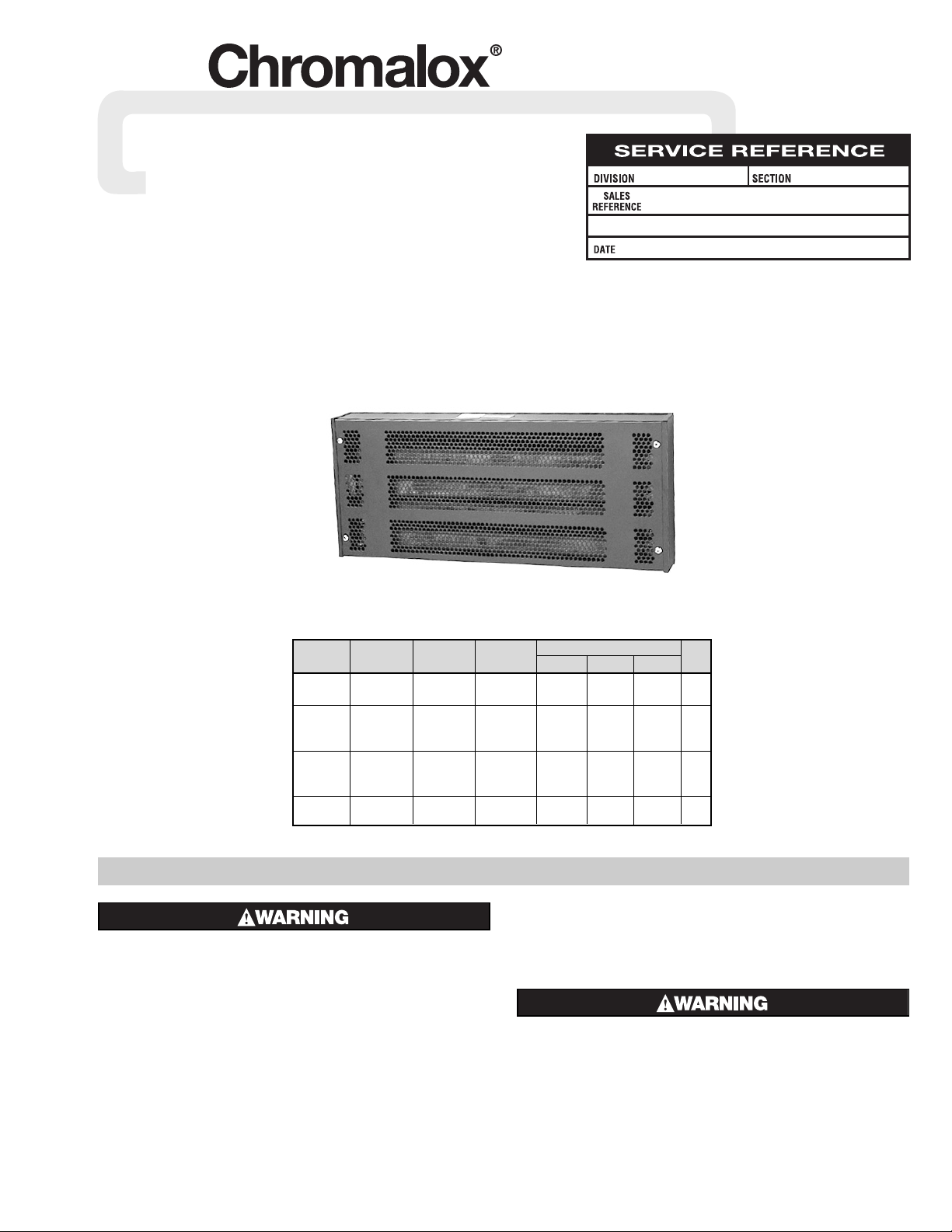
Industrial Wall Mounted Natural Convection
Space Heater - Type H
© 2010 Chromalox, Inc.
Specifications
GENERAL INFORMATION
ELECTRIC SHOCK HAZARD. Disconnect all power
before installing or servicing heater. Failure to do
so could result in personal injury or property damage. Heater must be installed by a qualified person
in accordance with the National Electrical Code,
NFPA 70.
1. All wiring should be done in accordance with local codes and the
National Electrical Code by a qualified person.
2. Connect air heaters to same line voltage as on heater nameplate.
3. Check possibility of corrosion if heaters are operated in atmos-
pheres other than air.
4. In general, locate heater approximately 1 foot from the floor, but
not less than 6 inches, for best overall results. Heater, however, can
be located anywhere to meet unique requirements of any particular application.
5. Heaters are mounted directly on any type of noncombustible surface—masonry, concrete, block, plastered walls, metal framework,
etc.— using appropriate hardware.
6. Standard heaters are mounted in a horizontal position with the terminal end on the left.
The system designer is responsible for the safety
of this equipment and should install adequate
back-up controls and safety devices with their
electric heating equipment. Where the consequences of failure could result in personal injury or
property damage, back-up controls are essential.
Model
Output Voltage Output
Dimensions (In.)
Wt.
(kW)(Vac)(BTUH)
Width Height Depth
Lbs.
H-1801 1.0 120 2 20-3/4 7-1/2 4-1/2 28
H-1801 1.0 240 2 20-3/4 7-1/2 4-1/2 28
H-2405 1.5 120 2 26-1/2 7-1/2 4-1/2 30
H-2405 1.5 240 2 26-1/2 7-1/2 4-1/2 30
H-2405 1.5 480 2 26-1/2 7-1/2 4-1/2 30
H-2406 2.0 120 4 26-1/2 11-1/4 4-1/2 32
H-2406 2.0 240 4 26-1/2 11-1/4 4-1/2 32
H-2406 2.0 480 4 26-1/2 11-1/4 4-1/2 32
H-2407 3.0 240 4 26-1/2 11-1/4 4-1/2 32
H-2407 3.0 480 4 26-1/2 11-1/4 4-1/2 32
Page 2
2
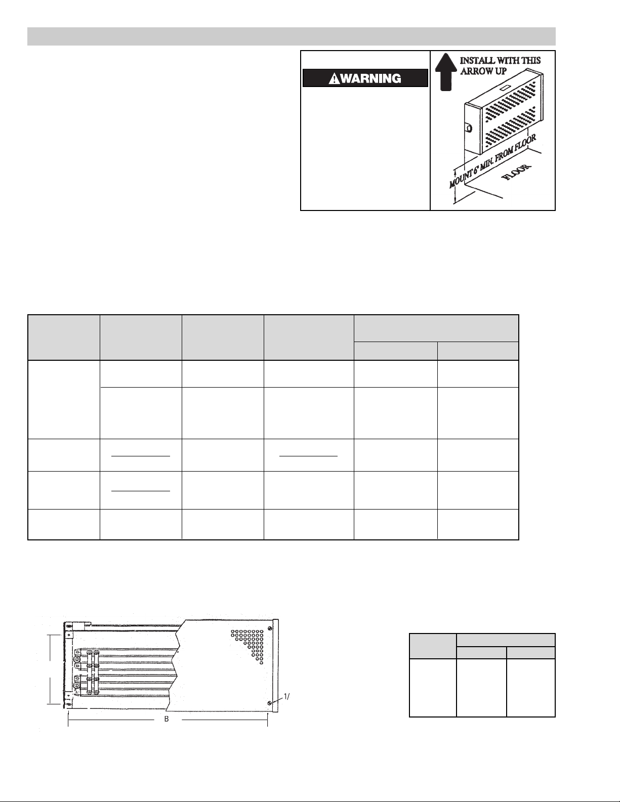
MOUNTING
1. Locate heater position on wall. This unit has special baffle plates
and vent holes in the cover to ensure sufficient convection currents.
Make sure that the heater is mounted so that the mounting label
located on the end cover points up (Fig. 1).
2. To locate mounting holes, see Specifications Table for heater in
question. In standard 16” stud center frame construction, locate
wall studding and locate 1 upper and 1 lower mounting hole in
center of stud.
3. Drill a pilot hole in metal or wood surfaces using a convenient
small size drill.
4. Drill the 4 holes in accordance with sizes in Table 1. Insert anchors
where applicable.
5. Remove cover screws.
6. Remove cover.
7. Fasten to wall with screws as listed in Table 1. Turn tight and then
back off 1/2 turn, to allow for expansion and contraction.
8. Replace heater cover — fasten with screws and washers removed
in Step 5.
Screw Size to Fit Hole Size
** in Heater Mounting Plates
Type Mounting Accessory ScrewDrill Size
Surface Hardware Type and Type Terminal End Opposite End
Round Head
Ackerman
Mach.Steel
1/2” Masonry 1/4 x 20 x 3” 1/4 x 20 x 2”
Concrete, Block Round Head. Mach.
Masonry
Lead Anchor
Steel or Pan
3/8” Masonry #14 x 3” #14 x 2”
Head Metal
(Self-tapping)
Wood Studs
Wood or Metal
#14 x 3” #14 x 2”
(Self-tapping)
Plaster Wall
Hollow or Toggle Bolt #7 1/4 x 4” 1/4 x 3”
Similar Type
* Metal Beam, Round Head
Channel, etc.
Nuts, Washers
Mach. Steel
#7 Twist 1/4 x 20 x 1-11/16”* 1/4 x 20 x 13/16”*
Table 1 — Suggested Heater Mounting Screws (Types and Sizes)
* If clearance permits, use washer, lockwasher and nut; otherwise, drill and tap. To these lengths add thickness of beam, washers, nut, etc.
** If mounting structure permits, except plastered hollow walls, explosive type anchors can be used. Suggest sizes noted in Table and/or sketches be used to determine size
of anchors.
Figure 1 - Mounting
4" Machine Screw (4 Pls.)
Model
Dimensions (In.)
AB
H-1801 5-3/4 19-1/2
H-2405 5-3/4 25
H-2406 9-7/8 25
H-2407 9-7/8 25
Heater Mounting Dimensions (In.)
Fire Hazard
• Not suitable for household or
residential use.
• Do not cover.
• Keep combustible material
away from heater.
• Do not recess heater into
wall.
Page 3

3
ELECTRIC SHOCK HAZARD. Any installation involving electric heaters must be performed by a qualified person and must be effectively grounded in
accordance with the National Electrical Code to
eliminate shock hazard.
Note: All wiring should be done in accordance with local codes
and the National Electrical Code by a qualified person.
1. Electrical wiring enters heater case through 7/8” opening in end of
heater.
2. Grounding conductor, with green insulation, should be secured to
grounding screw located on case.
OPERATION
HAZARD OF FIRE OR DISCOLORATION OF TEMPERATURE SENSITIVE FABRICS. Keep combustible
materials and such fabrics at least 4” away from
front of cover or above cover.
FIRE HAZARD. This heater is not intended for use in
hazardous atmospheres where flammable vapors,
gases, liquids or other combustible atmospheres are
present as defined in the National Electrical Code.
Failure to comply can result in explosion or fire.
ELECTRIC SHOCK HAZARD. Disconnect all power
before attempting to service this heater.
1. Following long periods of idleness, heater should be vacuumed
before start-up to remove accumulated combustible particles
which will incinerate causing smoking and consequent wall discoloration.
2. If heater is located in areas of heavy traffic, furnish suitable heater
guard (wall mounted pipe rail in front of case, for example) to prevent damage to heater.
MAINTENANCE
WIRING
RENEWAL PARTS IDENTIFICATION
l
l
Elemen
t
Air Space Between Wll and H
eat
Insulating Insulating Heater
Model Volts Watts Heating Element Bushing Bushing Cover
120 1000 SE-1850 – 120V - 500W (2) 032-010978-001 (4) 032-010978-002 (4) 152-108257-001
H-1801 240 1000 SE-1850 – 240V - 500W (2) 032-010978-001 (4) 032-010978-002 (4) 152-108257-001
480 1000 SE-1850 – 240V - 500W (2) 032-010978-001 (4) 032-010978-002 (4) 152-108257-001
120 1500 SE-2475 – 120V - 750W (2) 032-010978-001 (4) 032-010978-002 (4) 152-108257-002
H-2405 240 1500 SE-2475 – 240V - 750W (2) 032-010978-001 (4) 032-010978-002 (4) 152-108257-002
480 1500 SE-2475 – 240V - 750W (2) 032-010978-001 (4) 032-010978-002 (4) 152-108257-002
120 2000 SE-2450 – 120V - 500W (4) 032-010978-001 (8) 032-010978-002 (8) 152-108257-003
H-2406 240 2000 SE-2450 – 240V - 500W (4) 032-010978-001 (8) 032-010978-002 (8) 152-108257-003
480 2000 SE-2450 – 240V - 500W (4) 032-010978-001 (8) 032-010978-002 (8) 152-108257-003
120 3000 SE-2475 – 120V - 750W (4) 032-010978-001 (8) 032-010978-002 (8) 152-108257-003
H-2407 240 3000 SE-2475 – 240V - 750W (4) 032-010978-001 (8) 032-010978-002 (8) 152-108257-003
480 3000 SE-2475 – 240V - 750W (4) 032-010978-001 (8) 032-010978-002 (8) 152-108257-003
1 3
5
4
Page 4

2150 N. RULON WHITE BLVD., OGDEN, UT 84404
Phone: 1-800-368-2493 www.chromalox.com
Limited Warranty:
Please refer to the Chromalox limited warranty applicable to this product at
http://www.chromalox.com/customer-service/policies/termsofsale.aspx.
 Loading...