

Page 1
Regular Oil Heaters
Chromalox
®
DIVISION 4 SECTION
NWHO
SALES
REFERENCE
DATE
SERVICE REFERENCE
Installation, Operation
and
RENEWAL PARTS IDENTIFICATION
PE426-2
161-058063-001
JANUARY, 2003
(Supersedes PE426-1)
GENERAL
© 2010 Chromalox, Inc.
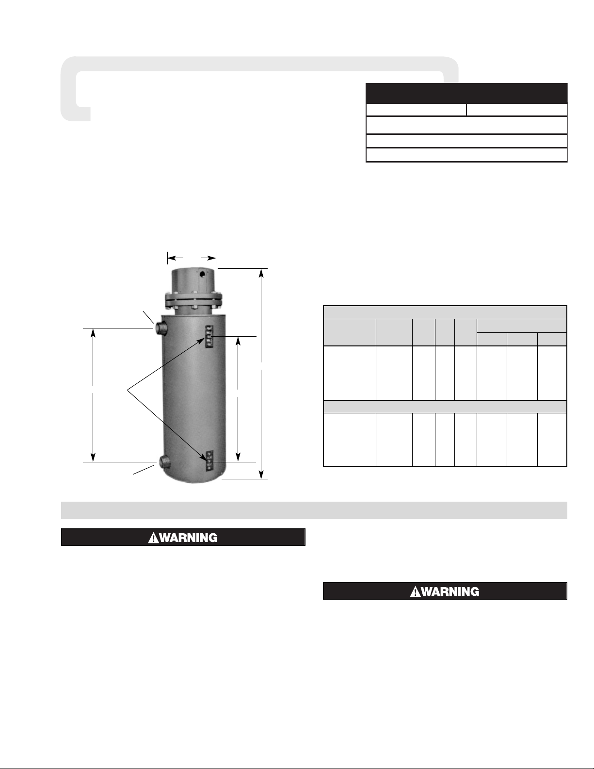
NWHO(F)-18 Circulation Heaters
(for Regular and Fuel Oil Heating)
FIRE/EXPLOSION HAZARD. This heater is not intended for use in hazardous atmospheres where flammable vapors, gases, liquids or other combustible atmospheres are present as defined in the National
Electrical Code. Failure to comply can result in personal injury or property damage
The NWHO(F)-18 series is a general purpose regular and fuel
oil solution circulation heater intended for use indoors.
The steel-sheathed tubular elements are centered in a steel
heating chamber and sealed into a removable steel flange. The
assembly is surrounded by insulation and a sheet metal jacket.
Depending upon the order specifications, the NWHO(F)-18
may or may not be factory equipped with an AR or other
Chromalox thermostat. Such thermostats function to control outlet
temperatures and to limit internal temperatures under abnormal
flow conditions. These controls do not fail-safe.
The system designer is responsible for the safety of
this equipment and should install adequate back-up
controls and safety devices with their electric heating
equipment. Where the consequences of failure could
result in personal injury or property damage, back-up
controls are essential.
Specifications — Table A
Fuel Oil Heaters
Dimensions (In.)
Model Volts Phase kW W/In
2
ABC
NWHO-1830R15 240 or 480 3 LL 30 20 53-7/8 32-11/16 29-3/16
NWHO-1840R15 240 or 480 3 LL 40 20 60-7/8 39-11/16 36-3/16
NWHO-1850R15 240 or 480 3 LL 50 20 68-1/2 47-5/16 43-13/16
NWHO-1860R15 240 or 480 3 LL 60 20 78 56-13/16 53-5/16
NWHO-1870R15 240 or 480 3 LL 70 20 87 65-13/16 62-5/16
NWHO-1880R15 240 or 480 3 LL 80 20 97 75-13/16 72-5/16
NWHO-1820F15 240 or 480 3 LL 20 12 53-7/8 32-11/16 29-3/16
NWHO-1825F15 240 or 480 3 LL 25 12 60-7/8 39-11/16 36-3/16
NWHO-1830F15 240 or 480 3 LL 30 12 68-1/2 47-5/16 43-13/16
NWHO-1835F15 240 or 480 3 LL 35 12 78 56-13/16 53-5/16
NWHO-1840F15 240 or 480 3 LL 40 12 87 65-13/16 62-5/16
NWHO-1845F15 240 or 480 3 LL 45 12 97 75-13/16 72-5/16
3/4-10 Tap
Mounting
Lugs
2-1/2” Pipe
Outlet
2-1/2” Pipe
Inlet
B
C
A
15-1/8”
Page 2
ELECTRIC SHOCK HAZARD. Disconnect all power
before installing or servicing heater. Failure to do so
could result in personal injury or property damage.
Heater must be installed by a qualified person in accordance with the National Electrical Code, NFPA 70.
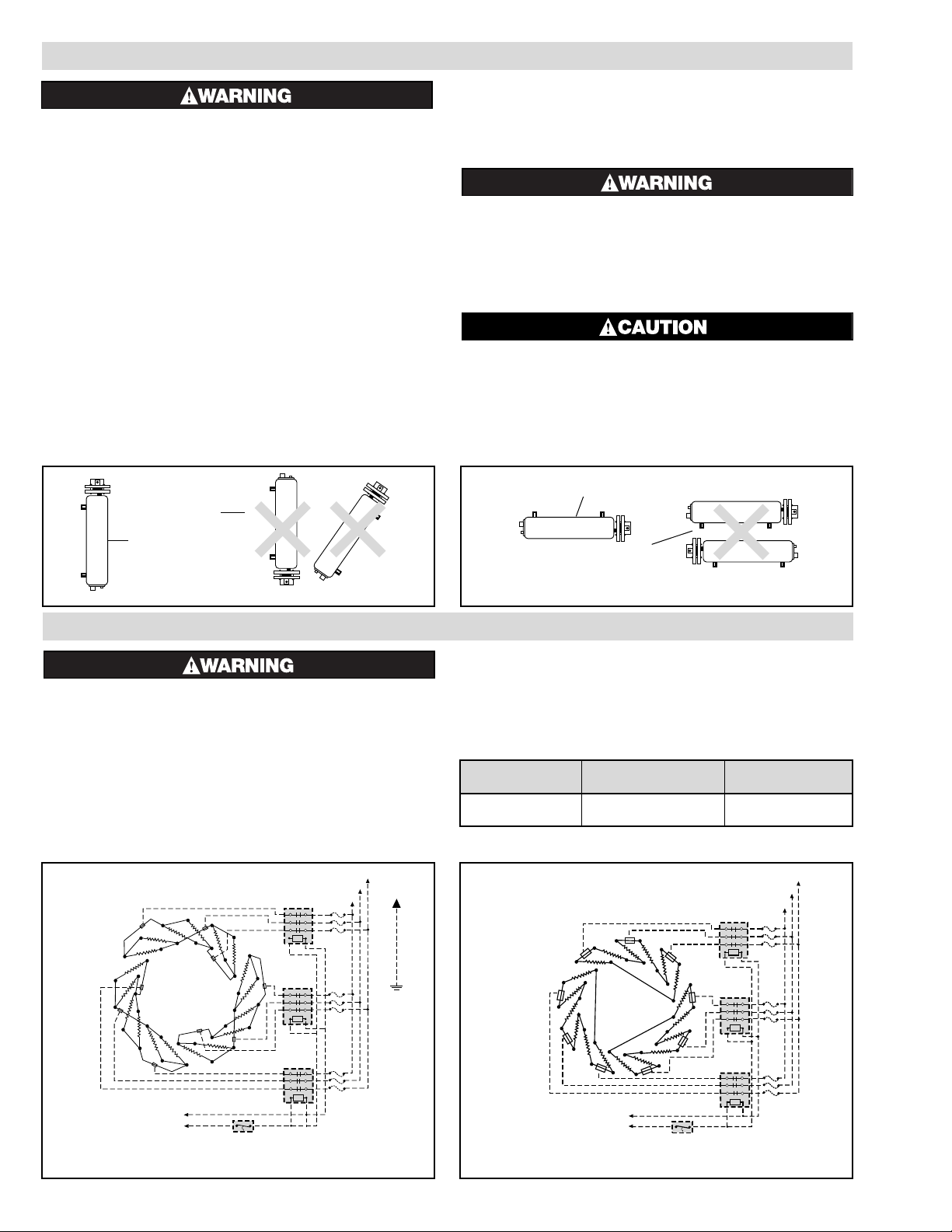
1. Vertical Mounting (Preferred)
When the heater is vertically mounted, the terminal housing will be
at the top of the heater. The inlet pipe will be located on the side
near the bottom of the heater and the outlet pipe at the top.
The axis of the chamber will be in a vertical position as in the
photo on previous page and as in Figure A. Note: A drain pipe
located at the bottom of the heater should be provided and enough
room left, when mounting heater, to allow draining the heater.
2. Horizontal Mounting (Optional)
CAUTION: When mounting heater horizontally, inlet and outlet
pipes must be up. In any other position, heater cannot be purged of
air, and elements may be seriously damaged. (See Figure B)
3. Whether vertically or horizontally, the heater should be rigidly
mounted so that vibration is at a minimum since excessive vibration will result in erratic thermostat operation. The NWHO(F)-18
is provided with mounting lugs to support the heating chamber.
(See photo)
4. By using a slotted mounting assembly on either of the lugs, the
heater chamber will be permitted to expand with increasing temperature.
5. Provide adequate space at terminal to end permit withdrawal of the
heater from chamber should servicing be required.
FIRE HAZARD. Since heaters are capable of developing high temperatures, extreme care should be taken
to:
A. Provide a minimum of 6” spacing from chamber and related
piping to nearest combustible material.
B. Do not operate near combustible fluids or vapors.
FREEZE HAZARD. This unit is equipped with a thermowell for process control or over-temperature
control. Do not allow moisture to accumulate in
thermowell. Freezing temperatures can cause
damage that may result in the heated medium
leaking into terminal enclosure.
240V 3–3Ø 480V 3–3Ø
Model Fig. Fig.
Any Heater 1 2
ELECTRIC SHOCK HAZARD. Any installation involving electric heaters must be performed by a qualified person and must be effectively grounded in
accordance with the National Electrical Code to
eliminate shock hazard.
1. Be sure line voltage matches heater voltage as shown on nameplate.
2. Electric wiring to heater must be installed in accordance with local
and National Electrical Codes by a qualified person as defined in
the NEC.
3. Power controllers must be used when heaters are rated for 480 volt
service or if the amperage rating of the heaters exceeds the contact
rating of the thermostat.
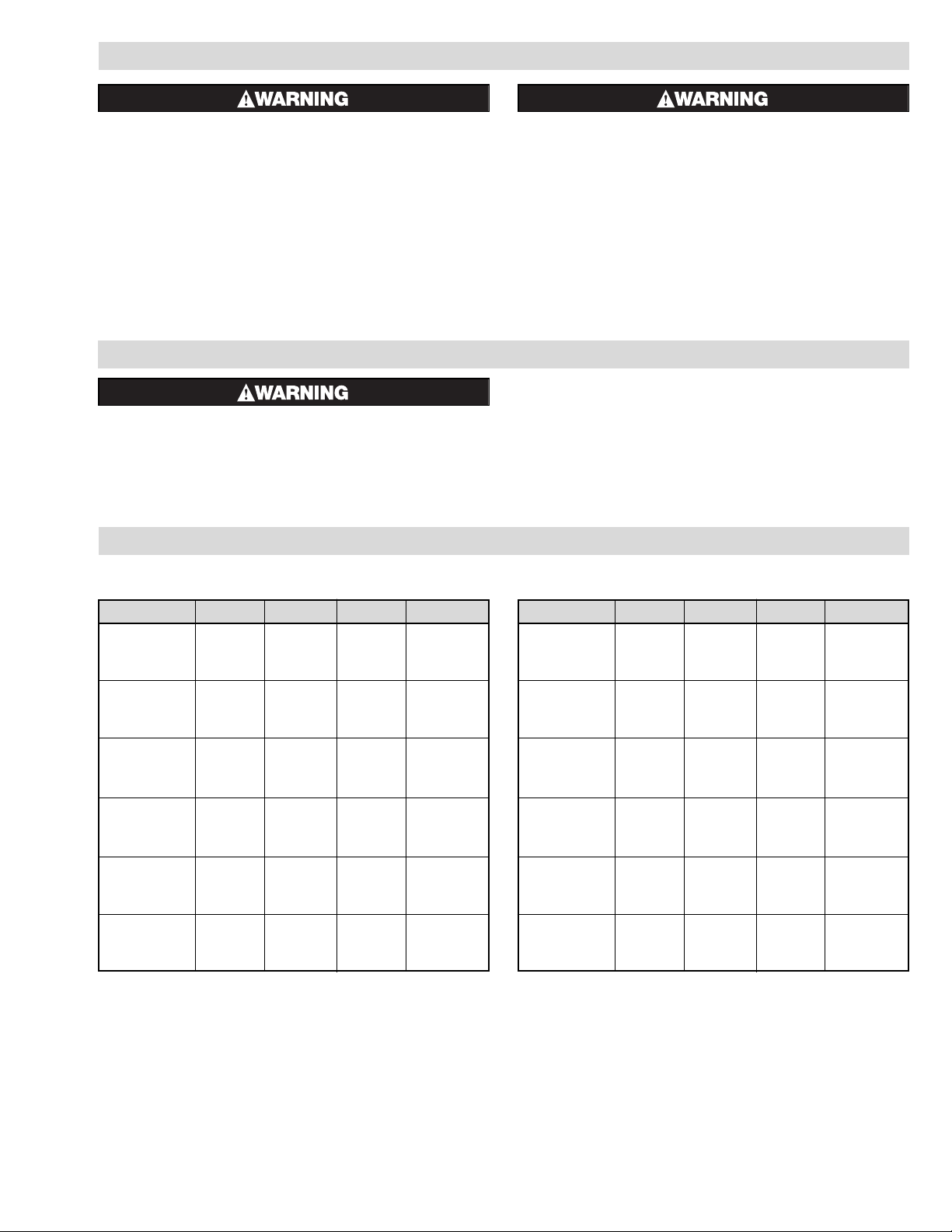
4. Refer to Wiring Diagram Table B for the proper wiring diagram
for connecting heater.
WIRING
Note: Dotted lines indicate “customer furnished.” However, thermostat may be furnished by Chromalox if so specified on the order.
INSTALLATION
Wiring Diagrams – Table B
L1
L2
L3
Contactor
Contactor
Contactor
Thermostat
120-v OR
240-v
Figure 1 – 240V 3-3 ø Δ
120-v OR
240-v
Figure 2 – 480V 3-3 ø Δ
L1
L2
L3
Contactor
Contactor
Contactor
Thermostat
Incorrect
Correct
Figure A — Vertical Mounting
Figure B — Horizontal Mounting
Correct
Incorrect
Page 3
Model Volts Phase kW Heating Element
NWHO-1830R15 240 3 LL 30 155-013185-331
NWHO(F)-1830R15 240 3 LL 30 155-045301-013
NWHO-1830R15 480 3 LL 30 155-013185-332
NWHO(F)-1830R15 480 3 LL 30 155-045301-014
NWHO-1840R15 240 3 LL 40 155-013185-004
NWHO(F)-1840R15 240 3 LL 40 155-045301-016
NWHO-1840R15 480 3 LL 40 155-013185-005
NWHO(F)-1840R15 480 3 LL 40 155-045301-017
NWHO-1850R15 240 3 LL 50 155-013185-007
NWHO(F)-1850R15 240 3 LL 50 155-045301-019
NWHO-1850R15 480 3 LL 50 155-013185-008
NWHO(F)-1850R15 480 3 LL 50 155-045301-020
NWHO-1860R15 240 3 LL 60 155-013185-010
NWHO(F)-1860R15 240 3 LL 60 155-045301-022
NWHO-1860R15 480 3 LL 60 155-013185-011
NWHO(F)-1860R15 480 3 LL 60 155-045301-023
NWHO-1870R15 240 3 LL 70 155-013185-013
NWHO(F)-1870R15 240 3 LL 70 155-045301-025
NWHO-1870R15 480 3 LL 70 155-013185-014
NWHO(F)-1870R15 480 3 LL 70 155-045301-026
NWHO-1880R15 240 3 LL 80 155-013185-016
NWHO(F)-1880R15 240 3 LL 80 155-045301-028
NWHO-1880R15 480 3 LL 80 155-013185-017
NWHO(F)-1880R15 480 3 LL 80 155-045301-029
RENEWAL PARTS IDENTIFICATION
Note: The “F” in NWHO(F) means forced circulation (ie: equipped with baffles.) When replacing the heating element, care must be taken that the baffles line up properly with the inlet and outlet pipes. The top of the
flange of replacement heating elements for forced circulation heaters is stamped near one edge with the letter “P”. The sub-assembly is positioned correctly when the “P” on the flange is in line with the inlet and outlet pipe. Incorrect placement will result in hindered circulation and possible failure of the element.
Note: When ordering parts for Model Numbers suffixed by “XX” or any other letter or letters not specifically identified on this instruction sheet, order Renewal Parts on special order basis, giving name of part, part
number and description.
MAINTENANCE
ELECTRIC SHOCK HAZARD. Disconnect all power
before installing or servicing heater. Failure to do so
could result in personal injury or property damage.
Heater must be installed by a qualified person in
accordance with the National Electrical Code, NFPA
70.
1. Remove heating element assembly periodically to check heater
sheath for scaling, corrosion or excessive oxidation. Correct operating conditions to minimize sheath deterioration.
2. Periodically check temperature control and limit control operation
to insure accurate and safe process operation.
3. Check all electrical connections periodically and retighten connec-
tions which may have loosened in service. Replace wire and wire
terminals which show signs of oxidation which would interfere
with establishment of reliable electrical connections.
Regular Oil Heaters
Model Volts Phase kW Heating Element
NWHO-1820F15 240 3 LL 20 155-013185-019
NWHO(F)-1820F15 240 3 LL 20 155-045301-001
NWHO-1820F15 480 3 LL 20 155-013185-020
NWHO(F)-1820F15 480 3 LL 20 155-045301-002
NWHO-1825F15 240 3 LL 25 155-013185-022
NWHO(F)-1825F15 240 3 LL 25 155-045301-004
NWHO-1825F15 480 3 LL 25 155-013185-023
NWHO(F)-1825F15 480 3 LL 25 155-045301-005
NWHO-1830F15 240 3 LL 30 155-013185-025
NWHO(F)-1830F15 240 3 LL 30 155-045301-007
NWHO-1830F15 480 3 LL 30 155-013185-026
NWHO(F)-1830F15 480 3 LL 30 155-045301-008
NWHO-1835F15 240 3 LL 35 155-013185-028
NWHO(F)-1835F15 240 3 LL 35 155-045301-010
NWHO-1835F15 480 3 LL 35 155-013185-029
NWHO(F)-1835F15 480 3 LL 35 155-045301-011
NWHO-1840F15 240 3 LL 40 155-013185-031
NWHO(F)-1840F15 240 3 LL 40 155-045301-031
NWHO-1840F15 480 3 LL 40 155-013185-032
NWHO(F)-1840F15 480 3 LL 40 155-045301-032
NWHO-1845F15 240 3 LL 45 155-013185-034
NWHO(F)-1845F15 240 3 LL 45 155-045301-034
NWHO-1845F15 480 3 LL 45 155-013185-035
NWHO(F)-1845F15 480 3 LL 45 155-045301-035
Fuel Oil Heaters
OPERATION
FIRE/EXPLOSION HAZARD. Do not exceed the
Pressure-Temperature rating of the flange as listed in
ANSI B16.5.
IMPORTANT: It is the responsibility of the purchaser of the heater to make the ultimate choice of
sheath material based upon his knowledge of the
chemical composition of the corrosive solution,
character of the materials entering the solution,
and controls which he maintains on the process.
Sheath corrosion can result in a ground fault
which, depending upon the solution being heated,
can cause an explosion or fire.
1. Do not heat solutions that are corrosive to the heating element
sheath or the heating chamber.
2. Terminal ends of heater must be protected from drippings, con-
densation, spray or direct spill-over of material. Their presence at
the terminals may damage heater electrical insulation. Liquid-tight
terminal enclosures are available to protect heater. Check with
local sales office.
3. If foreign material is carried by the liquid flow, install suitable fil-
ters in the inlet pipe line to the heater.
4. Do not allow heater to operate when liquid flow is interrupted.
Page 4

2150 N. RULON WHITE BLVD., OGDEN, UT 84404
Phone: 1-800-368-2493 www.chromalox.com
TA - U0 - EF
Litho in U.S.A.
Limited Warranty:
Please refer to the Chromalox limited warranty applicable to this product at
http://www.chromalox.com/customer-service/policies/termsofsale.aspx.
 Loading...