

Page 1
Chromalox
®
DIVISION 4 SECTION
GCH-GCHIS
SALES
REFERENCE
DATE
SERVICE REFERENCE
Installation, Operation
and
RENEWAL PARTS IDENTIFICATION
PE419-5
161-027331-001
FEBRUARY, 2009
(Supersedes PE419-4)
GENERAL
© 2010 Chromalox, Inc.
GCH and GCHIS-6 Circulation Heaters
For Steam, Gas and Air Heating
Read and understand all instructions before
installing, servicing or operating product. Failure
to do so could result in personal injury or property
damage.
The GCH and GCHIS-6 series is a general-purpose gas or steam
circulation heater intended for use indoors.
The 6 INCOLOY® sheathed tubular elements are centered in a 5”
diameter heating chamber and welded to a removable flange. The
assembly is surrounded by 1-1/2” insulation and sheet metal jacket.
The GCH series has a steel flange and chamber. The GCHIS series has
stainless steel flange and chamber.
Depending upon the order specifications, the GCH-GCHIS-6 may
or may not be factory equipped with an AR or other Chromalox thermostat. Such thermostats function to control outlet temperatures and to
limit internal temperatures under abnormal flow conditions. These
controls do not fail safe.
The system designer is responsible for the safety
of this equipment and should install adequate
back-up controls and safety devices with their
electric heating equipment. Where the consequences of failure could result in personal injury or
property damage, back-up controls are essential.
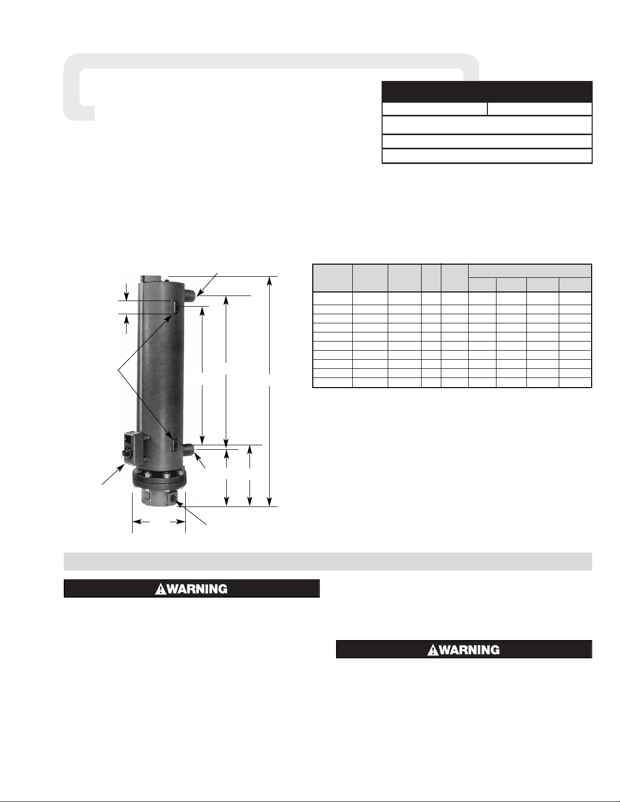
Specifications — Table A
Dimensions (In.)
Model Volts Phase kW W/In
2
AB C D
GCH-60905 240 or 480 1 or 3 LL 9 23.8 41-3/4 30 25 11-3/8
GCH-61205 240 or 480 1 or 3 LL 12 23.1 48-3/4 37 25 14-7/8
GCH-62005 240 or 480 1 or 3 LL 20 23.3 60-1/4 48-1/2 25 20-5/8
GCH-62505 240 or 480 3Y 25 22.9 73-5/8 61-7/8 25 27-5/16
GCH-63005 240 or 480 3Y 30 22.7 86-5/8 74-7/8 25 33-7/8
GCHIS-6045 240 or 480 3Y 4 15 41-3/4 30 25 11-3/8
GCHIS-6085 240 or 480 3Y 8 15 48-3/4 37 25 14-7/8
GCHIS-6125 240 or 480 3Y 12 15 60-1/4 48-1/2 25 20-5/8
GCHIS-6155 240 or 480 3Y 15 15 73-5/8 61-7/8 25 27-5/16
GCHIS-6205 240 or 480 3Y 30 15 86-5/8 74-7/8 25 33-7/8
A
B
12-1/32”
C
8-3/4”
1-1/4”
8”
Mtg. Lugs
3/8-16 Tap
1-1/2” Deep
1-3/8” K.O.
For 1” Conduit
1” Pipe
Inlet
1” Pipe
Outlet
AR
Thermostat
Page 2
ELECTRIC SHOCK HAZARD. Any installation involving electric heaters must be performed by a qualified person and must be effectively grounded in
accordance with the National Electrical Code to
eliminate shock hazard.
1. Be sure line voltage matches heater voltage (on nameplate).
2. Electric wiring to heater must be installed in accordance with local
codes and the National Electrical Codes.
3. Because of the high operating temperatures expected, 250˚C wire
should be used.
4. Power controls must be used when heaters are rated 3 phase and
when the heater amperage exceeds the rating of the thermostat.
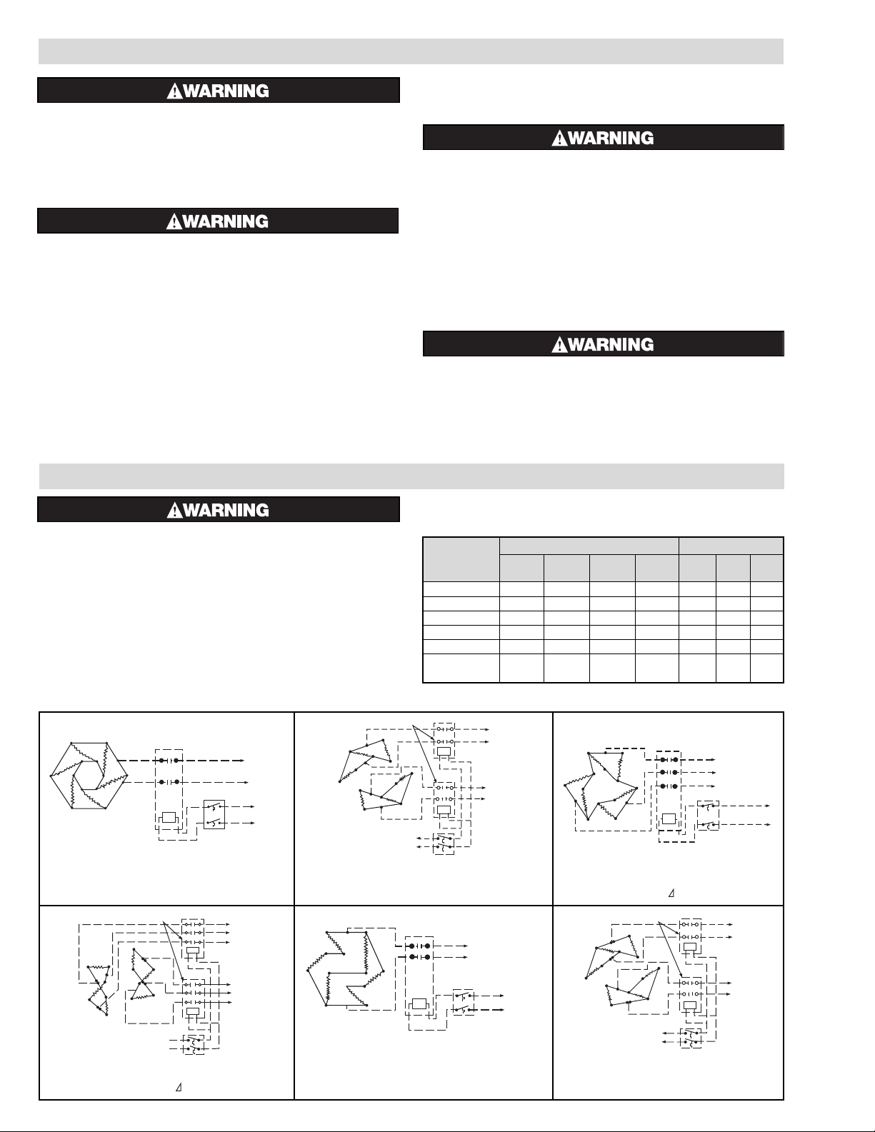
5. Refer to Wiring Diagram Table B, to properly connect the heater.
Table B — Wiring Diagrams
WIRING
240V 480V
Model 1ø 2-1ø 3ø 2-3ø 1ø 2-1ø 3ø
Fig. No. Fig. No. Fig. No. Fig. No. Fig. No. Fig. No.Fig. No.
GCH-60905 1 — 3 — 5 — 7
GCH-61205 — 2 3 — 5 — 7
GCH-62005 — 2 — 4 5 — 7
GCH-62505 — — — 4 — 6 7
GCH-63005 — — — 4 — — 7
GCHIS 4, 8
—— 8 ———9
12, 15,20 kW
INSTALLATION
ELECTRIC SHOCK HAZARD. Disconnect all power
before installing or servicing heater. Failure to do
so could result in personal injury or property damage. Heater must be installed by a qualified person
in accordance with the National Electrical Code,
NFPA 70
.
FREEZE HAZARD. This unit is equipped with a thermowell for process control or over-temperature
control. Do not allow moisture to accumulate in
thermowell. Freezing temperatures can cause
damage that may result in the heated medium
leaking into terminal enclosure.
1. Vertical mounting (axis of chamber vertical as in photo on previ-
ous page) is preferred.
2. To avoid excess temperatures at electrical wiring, mount heater
with terminal enclosure at bottom and use lower nozzle as inlet to
the circulating steam, air or gas.
3. The GCH-GCHIS-6 series of circulation heaters are provided with
mounting lugs to support the heater chamber. Refer to photo on
previous page for location of these mounting lugs.
4. Mount heaters to permit unrestrained expansion of chamber due to
temperature. This can be accomplished by using a slotted mounting assembly on either of the lugs.
FIRE HAZARD. Since heaters are capable of developing high temperatures, extreme care should be
taken to:
A. Provide minimum of 6” spacing from a chamber
and related piping to nearest combustible material.
B. Avoid operation of heater near combustible fluids
or in combustible vapor or gas laden atmosphere.
5. Provide adequate space at terminal end to permit withdrawal of the
heater from chamber should servicing be required.
6. If two or more heaters are needed to provide the needed heating
capacity, arrange them for series gas or vapor flow.
EXPLOSION HAZARD. When heating in closed vessels,
controls and back-up controls must be used to regulate build-up of temperature and/or pressure.
7. A pressure relief valve should be provided by customer at outlet
of vessel. There should be no other valving between vessel and
LINE
CONTACTOR
THERMOSTAT
120V, 240V
Figure 1 – GCH6
240V, 1ø
LINE
CONTACTORS
THERMOSTAT
120V or
240V
Figure 2 – GCH6
240V, 2-1ø
CONTACTOR
THERMOSTAT
120V, 240V
Figure 3 – GCH6
240V, 3ø
L1
L2
L3
CONTACTORS
THERMOSTAT
120V
or 240V
Figure 4 – GCH6
240V, 2-3ø
1L1
1L2
1L3
2L1
2L2
2L3
CONTACTORS
THERMOSTAT
120V or 240V
Figure 5 – GCH6
480V, 1ø
LINE
CONTACTORS
THERMOSTAT
120V or
240V
Figure 6 – GCH6
480V, 2-1ø
LINE
Page 3

OPERATION
1. Do not heat materials that are corrosive to the heating element
sheath or chamber.
2. Terminal ends of heater must be protected from drippings, con-
densation, spray or direct spill-over of material whose presence at
the terminals may damage heater electrical insulation. Liquid-tight
terminal enclosures are available to protect heater. Consult your
local Chromalox Sales office.
3. If foreign material is carried by the gaseous flow, install suitable
filters in the inlet pipe line to the heater.
4. Do not allow heater to operate when steam, air or gas flow is inter-
rupted.
FIRE/EXPLOSION HAZARD. Safe operating conditions depend on operating pressure, mass velocity
of gas and discharge temperature of the gas. At a
given discharge gas temperature, heater element
sheath temperature and pipe body temperature
tend to increase as gas flow (mass velocity)
decreases. The standard GCH-6 has a 750˚F limitation on the carbon steel body and a 1500˚F limit on
the INCOLOY sheath elements. Check factory if any
doubt exists as to temperatures that will be
encountered in your specific application. At pipe
body temperatures above 750˚F, stainless steel
pipe body is required (model GCHIS).
FIRE/EXPLOSION HAZARD. Do not exceed the
Pressure-Temperature rating of the flange as listed in ANSI B16.5.
WIRING
CONTACTOR
THERMOSTAT
120V, 240V
Figure 7 – GCH6
480V, 3ø
L1
L2
L3
CONTACTOR
THERMOSTAT
120V, 240V
Figure 8 – GCHIS
240V, 3øY
L1
L2
L3
CONTACTOR
THERMOSTAT
120V, 240V
Figure 9 – GCHIS
40V, 3øY
L1
L2
L3
166-075229-014
166-014828-024
166-075229-018
240V LINE
FIGURE A
240V, 3ø (Parallel) Connected
166-075229-014
166-014828-024
480V LINE
FIGURE B
480V, 3ø (Series) Connected
Instructions for converting
GCH6, 240V, 3ø to GCH6, 480V, 3ø
1. Remove all jumper straps and separate
according to different lengths.
2. Discard jumper straps 166-075229-018
(1-1/4” long).
3. Reassemble jumper straps 166-014828-
024 (2-1/2” long) and 166-075229-014
(1-1/2” long) as in Figure B.
4. Replace washers and nuts.
5. Check circuits.
NOTE: Broken Lines Indicate “Customer-furnished”. However, thermostat could have been furnished by chromalox if so specified on order.
MAINTENANCE
ELECTRIC SHOCK HAZARD. Disconnect all power
before installing or servicing heater. Failure to do so
could result in personal injury or property damage.
Heater must be installed and serviced by a qualified
person in accordance with the National Electrical
Code, NFPA 70.
1. Remove heating element assembly periodically to check heater
sheath for corrosion or excessive oxidation. Correct operating conditions to minimize sheath deterioration.
2. Periodically check temperature control and limit control operation
to insure accurate and safe process operation.
3. Check all electrical connections periodically and retighten con-
nections which may have loosened in service. Replace wire and
wire terminals that show signs of oxidation which would interfere
with establishment of reliable electrical connections.
NOTE: Maintenance intervals to be determined by the user based on
their knowledge of the heated medium and operating conditions.
Page 4

2150 N. RULON WHITE BLVD., OGDEN, UT 84404
Phone: 1-800-368-2493 www.chromalox.com
TA - U0 - EF
Litho in U.S.A.
RENEWAL PARTS
Note: When ordering parts for Model Numbers suffixed by “XX” or any other letter or any other letters not specifically identified on this instruction sheet, order Renewal Parts on special order basis, giving
name of part, part number, model number and description. Note: Number in ( ) indicates quantity of same part number used. Model GCHIS - contact local Chromalox Representative.
Catalog Number Volts Phase kW Heating Element
240 1 9 155-115143-001
GCH-60905
240 3 LL 9 155-115143-002
480 1 9 155-115143-003
482 3 LL 9 155-115143-004
240 2-1 12 155-115143-006
GCH-61205
240 3 LL 12 155-115143-007
480 1 12 155-115143-008
480 3 LL 12 155-115143-009
240 2-1 20 155-115143-011
GCH-62005
240 3 LL 20 155-115143-012
480 1 20 155-115143-013
480 3 LL 20 155-115143-014
240 2-3 LL 25 155-115143-016
GCH-62505 480 2-1 25 155-115143-017
480 3 LL 25 155-115143-018
GCH-63005
240 2-3 LL 30 155-115143-020
480 3 LL 30 155-115143-021
PARTS COMMON TO ALL HEATERS
AR5524 Thermostat 300-013863-015
Standard Gasket 132-017222-016
Limited Warranty:
Please refer to the Chromalox limited warranty applicable to this product at
http://www.chromalox.com/customer-service/policies/termsofsale.aspx.
 Loading...