

Page 1
Chromalox
®
(Supersedes PE414-2)
PE414-3
NWH
161-304777-001
MAY, 2007
4
RENEWAL PARTS IDENTIFICATION
Installation, Operation
and
Circulation
Heaters for Oil or Water Heating
© 2010 Chromalox, Inc.
Specifications – Table A
GENERAL
READ ALL INSTRUCTIONS BEFORE USE
FIRE/EXPLOSION HAZARD. Ordinary location
heaters (designated E1) are not intended for use in
hazardous atmospheres where flammable vapors,
gases, liquids or other combustible atmospheres are
present as defined in the National Electrical Code.
Failure to comply can result in personal injury or
property damage.
This design has the versatility of field adjustments of voltage
kW through various wiring combinations.
The NWHSRG model is a general purpose water circulation
heater intended for indoor use. E2 designs have a Moisture
Resistant/Explosion Resistant enclosure. Designs are up to 40kW
- DO NOT USE THE NWHSRG MODEL FOR OIL.
The NWHOSR model is a general-purpose regular and fuel oil
solution circulation heater intended for use indoors. E2 designs
have a Moisture Resistant/Explosion Resistant enclosure. Designs
are up to 10kW - DO NOT USE THE NWHOSR MODEL FOR
WATER. Ensure the wiring guide for oil is used for the correct
wiring diagram.
Both the NWHSRG and NWHOSR use six INCOLOY
®
sheath
elements welded to a steel 2.5” screw plug. The vessel is cast iron
and is surrounded by 1.5” insulation and a sheet metal jacket. For
water applications, the vessel has a galvanized coating. A J-type
thermocouple in a thermowell is standard. These
versaTHERM
TM
heaters
are designed for 150 psig max. at 35°F min. to 300°F max.
IMPORTANT: It is the responsibility of the purchaser of
the heater to make the ultimate choice of sheath
material based upon his knowledge of the chemical
composition of the corrosive solution, character of the
materials entering the solution, and controls which he
maintains on the process.
ELECTRIC SHOCK HAZARD. Disconnect all power
before installing or servicing heater. Failure to do
so could result in personal injury or property damage. Heater must be installed or serviced by a
qualified person in accordance with the National
Electrical Code. NFPA 70.
The system designer is responsible for the safety
of this equipment and should install adequate
back-up controls and safety devices with their
electric heating equipment. Where the consequences of failure could result in personal injury or
property damage, back-up controls are essential.
If foreign material is to be carried by the liquid flow, install
suitable filters in the inlet pipe to the heater.
Ensure the temperature/pressure is controlled below the vapor
point of the liquid at all times and is within the temperature/pressure ratings for this heater.
Heating elements must be completely immersed in liquid when
energized.
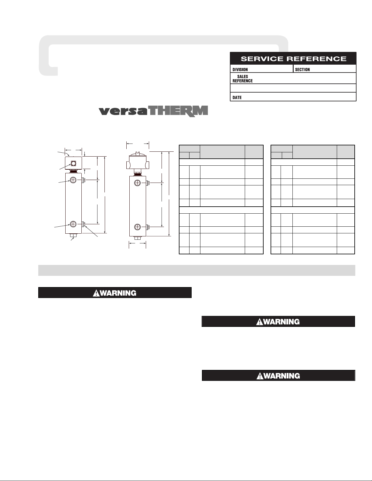
Dim. (In.)
A B Model PCN
Cast Iron Body / Oil .5 to 10 kW
29 19 NWHOSR-06-04P5-E1 100108
29 19 NWHOSR-06-04P5-E1 100116
41 30
3
/4 NWHOSR-06-005P-E1 100124
29 19 NWHOSR-06-006P-E1 100132
29 19 NWHOSR-06-006P-E1 100140
41 30
3
/4 NWHOSR-06-010P-E1 100159
Galvanized Body / Water .5 to 40 kW
29 19 NWHSRG-06-018P-E1 100010
29 19 NWHSRG-06-018P-E1 100028
41 30
3
/4 NWHSRG-06-020P-E1 100036
29 19 NWHSRG-06-024P-E1 100044
29 19 NWHSRG-06-024P-E1 100079
41 30
3
/4 NWHSRG-06-040P-E1 100095
A
B
6"
Rotatable
Terminal
Cover
1" Conduit
Opening
Outlet
1" FNPT
Inlet
1" FNPT
1" FNPT Pipe Plug
(or Inlet)
8 / "
1
2
4"
2 Mtg. Lugs
/ "-13 x / " Deep
1
1
2
2
Specifications – Table B
Dim. (In.)
A B Model PCN
Cast Iron Body / Oil .5 to 10 kW
32 19 NWHOSR-06-04P5-E2 100255
32 19 NWHOSR-06-04P5-E2 100263
44 30
3
/4 NWHOSR-06-005P-E2 100271
32 19 NWHOSR-06-006P-E2 100280
32 19 NWHOSR-06-006P-E2 100298
44 30
3
/4 NWHOSR-06-010P-E2 100300
Galvanized Body / Water .5 to 40 kW
32 19 NWHSRG-06-018P-E2 100327
32 19 NWHSRG-06-018P-E2 100343
44 30
3
/4 NWHSRG-06-020P-E2 100351
32 19 NWHSRG-06-024P-E2 100360
32 19 NWHSRG-06-024P-E2 100378
44 30
3
/4 NWHSRG-06-040P-E2 100386
Dimensions (Inches)
A
B
11"
7-7/8"
6"
E1
E2
TM
Page 2
INSTALLATION
ELECTRIC SHOCK HAZARD. Disconnect all power
before installing heater. Failure to do so could
result in personal injury or property damage.
Heater must be installed by a qualified person in
accordance with the National Electrical Code.
NFPA 70.
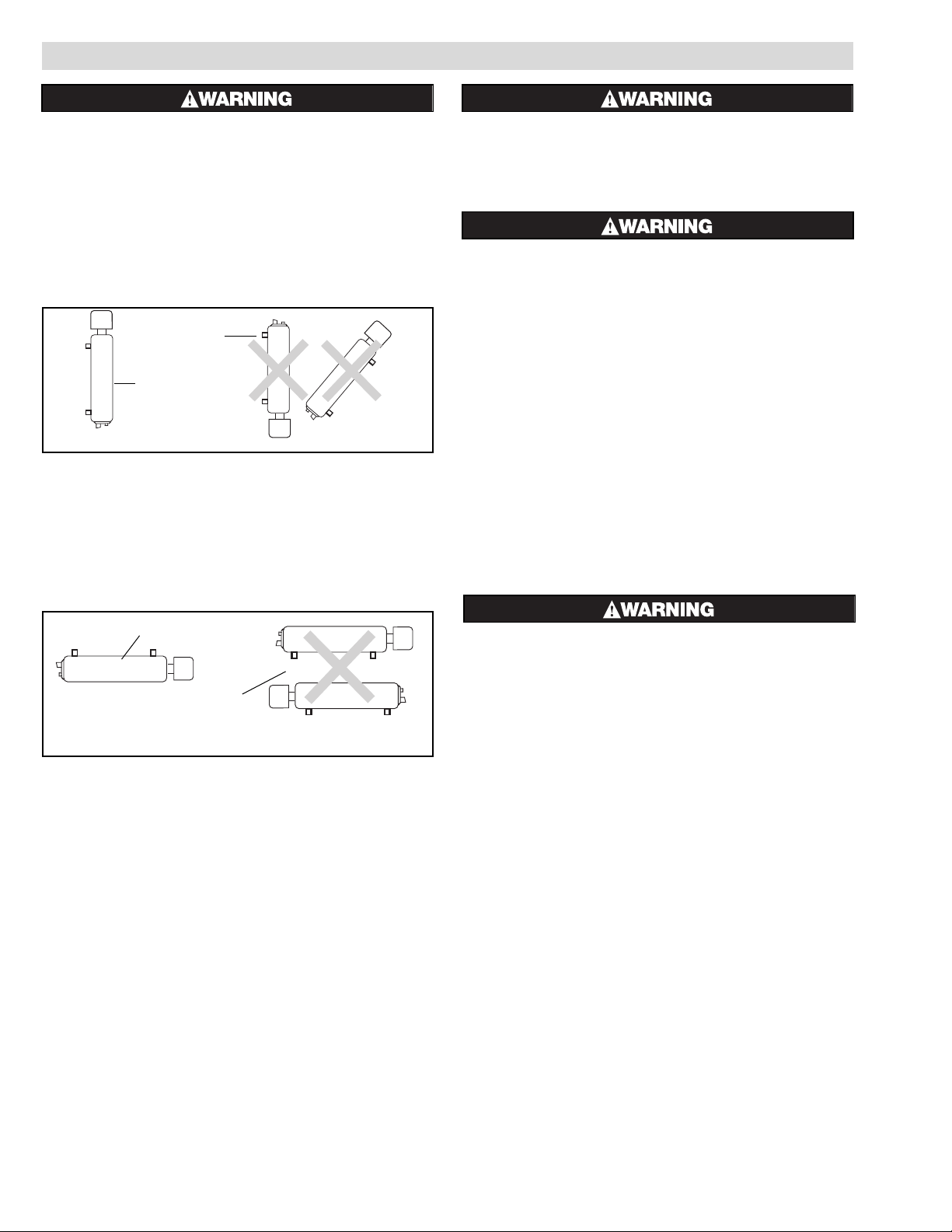
1. Vertical Mounting (Preferred) —
When the heater is vertically mounted, the electrical enclosure
will be at the top of the heater. The inlet pipe will be located on
the side near the bottom of the heater and the outlet pipe at the
top.
The axis of the chamber will be in a vertical position as in
Figure A.
2. Horizontal Mounting (Optional) —
When mounting heater horizontally, inlet and outlet pipes must
be up. In any other position, heater cannot be purged of air, and
elements may be seriously damaged. (See Figure B.)
Note: Heater cannot be completely drained in the horizontal position. When mounting the heater, allow adequate spacing for draining the heater.
3. Whether vertical or horizontal, the heater should be rigidly
mounted so that vibration is at a minimum since excessive
vibration will result in erratic thermostat operation (if thermostat is used instead of thermocouple). The NWHOSR/NWHSRG is provided with mounting lugs to support the heating
chamber. (See drawing on front page.)
FIRE HAZARD. An integral thermostat, if used, is
designed for temperature control service only.
Because the thermostat is not fail safe, it should
not be used for temperature limiting duty. Wiring to
this device is the responsibility of the user.
FIRE HAZARD. Since heaters are capable of developing high temperatures, extreme care should be
taken to:
A. Provide minimum of 6” spacing from chamber
and related piping to nearest combustible material.
B. Do not operate near combustible fluids or in
combustible vapor or gas laden atmosphere.
4. Ensure clearance is available to allow removal of the heating
assembly from the chamber. Generally this is a space extending from the electrical enclosure equal to the length of the
entire unit. Otherwise, removing the entire heater may be
required to service the heater.
5. Standard side inlet can be changed to the end connection for
ease of piping.
6. Mount heaters to permit unrestrained expansion of the chamber
due to temperature. This may be accomplished by using a slotted mounting assembly on either of the mounting lugs.
7. If two or more heaters are required to provide the heating
capacity, pipe units in series or parallel.
EXPLOSION HAZARD. When heating in closed vessels, controls and back-up controls must be used
to regulate build-up of temperature and/or pressure.
8. A pressure relief valve should be provided by customer at out-
let of vessel. There should be no other valving between vessel
and relief valve.
9. Install adequate collection/drainage below the heater to prevent
damage to other materials and property at your location.
Figure B — Horizontal Mounting
Figure A — Vertical Mounting
Correct
Correct
Incorrect
Incorrect
2
Page 3
3
WIRING
ELECTRIC SHOCK HAZARD. Any installation involving electric heaters must be performed by a qualified person and must be effectively grounded in
accordance with the National Electrical Code to
eliminate shock hazard.
Ensure the correct Wiring Guide is used for your
heated medium and model type, and ensure the
correct wiring diagram is used. Miswiring could
result in an unsafe wattage.
1. Be sure line voltage matches your intended voltage and does
not exceed the max voltage on the nameplate.
2. Electric wiring to heater must be installed in accordance with
local and National Electrical Codes by a qualified person as
defined in the NEC.
3. Power controllers must be used with this product.
4. Electrical wiring to heater should be with rigid conduit or flex-
ible conduit to keep corrosive vapors and liquids out of the
electrical enclosure. If high humidity is encountered, the conduit should slope down away from the heater.
5. Refer to appropriate wiring diagram for your model heater
from the Wiring Guide (on next two pages).
The specific Wiring Guide provides easy to follow steps to
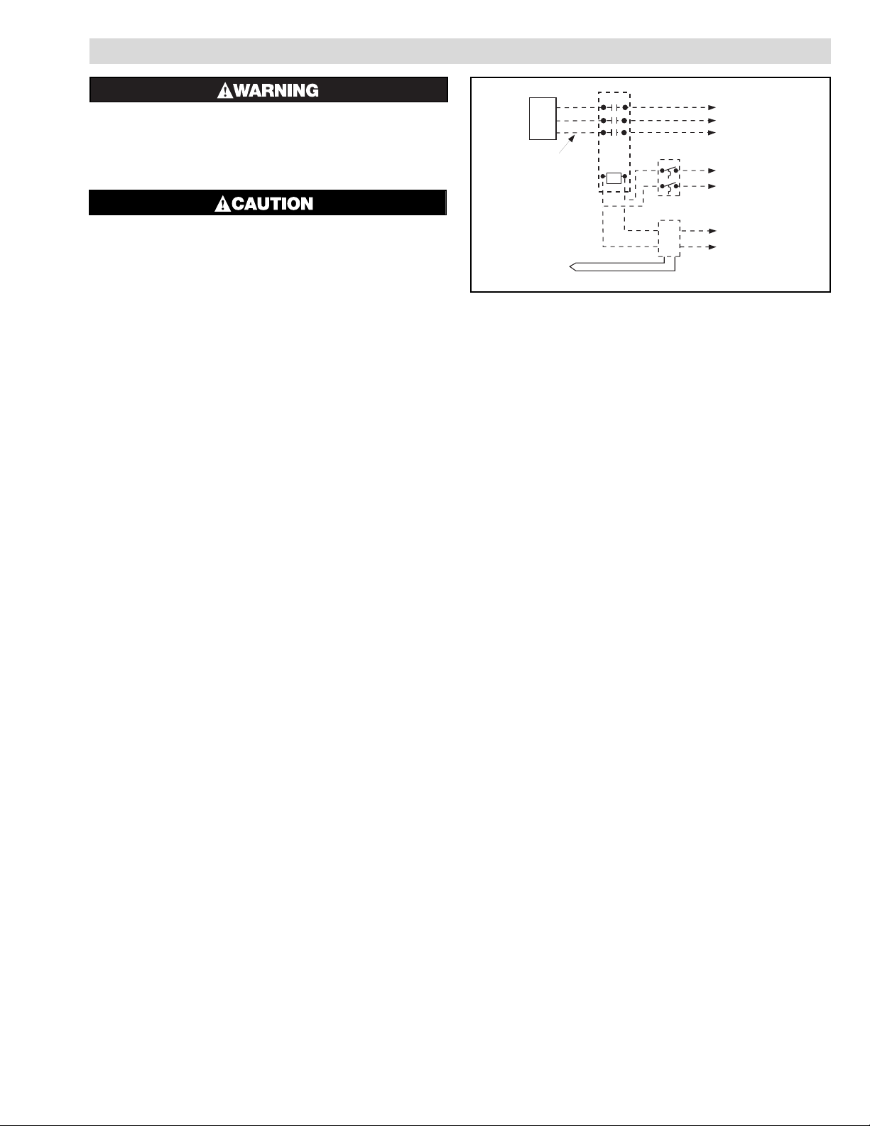
determine the appropriate wiring diagram for your heater installation. Figure 1 may be referenced as a general diagram of how
a contactor and temperature control are used in conjunction
with the specific wiring diagrams.
6. Use ground fault protection equipment where electrical insula-
tion failure can cause process problems.
7. When element wattages are not equal, heaters must not be con-
nected in series.
8. If flexible cord is employed, a watertight connector should be
used for entry of the cord into the electrical enclosure. Outdoor
applications require liquid-tight conduit and connectors.
9. If application uses a standard PCN at different voltages and
kWs from the Wiring Guide, refer to the Customer Wiring
Guide Supplement if included with these instructions, or contact Customer Service at (800) 368-2493.
Note: Dotted lines indicate “customer furnished.” Complete power/temperature
control panels or components are available. Contact Chromalox 1-800-443-2640
for more information and assistance.
Contactor
Thermostat
L1
L2
To equipment disconnect
with overcurrent protection
L1
L2
L3
Heater
1Ø or 3Ø: Refer to wiring
diagram designated from the
the Wiring Guide for specific
wiring directions to
the heater.
or
Temperature control
L1
L2
Thermocouple
}}
Type "J"
thermocouple
is standard.
Control voltage
Figure 1
Page 4

Oil Applications
Approx. Watts
Wiring
Watts-Volts Circuit-Phase (amps) /Sq. In. Diag. #
PCN 100140 (P/N 052-304749-005)
PCN 100298 (P/N 052-304749-305)
.5kW - 240V 1-3Ph (1.3 amps) 2 #6
.75kW - 120V 1-1Ph (7 amps) 5 #13*
.75kW - 208V 1-3Ph (2.1 amps) 5 #12*
1.5kW - 120V 1-1Ph (13 amps) 5 #7
1.5kW - 120V 2-1Ph (2 x 7 amps) 5 #8
1.5kW - 208V 1-3Ph (4.2 amps) 5 #4
1.5kW - 240V 1-1Ph (7 amps) 5 #10
1.5kW - 240V 1-3Ph (3.7 amps) 5 #3
2.25kW - 208V 1-1Ph (11 amps) 15 #13*
2.25kW - 208V 1-3Ph (7 amps) 15 #11*
3.0kW - 240V 1-1Ph (13 amps) 20 #13*
3.0kW - 240V 1-3Ph (8 amps) 20 #11*
4.5kW - 208V 1-1Ph (22 amps) 15 #7
4.5kW - 208V 2-1Ph (2 x 11 amps) 15 #8
4.5kW - 208V 1-3Ph (13 amps) 15 #1
4.5kW - 208V 2-3Ph (2 x 7 amps) 15 #2
6.0kW - 240V 1-1Ph (25 amps) 20 #7
6.0kW - 240V 2-1Ph (2 x 13 amps) 20 #8
6.0kW - 240V 1-3Ph (15 amps) 20 #1
6.0kW - 240V 2-3Ph (2 x 8 amps) 20 #2
6.0kW - 480V 1-1Ph (13 amps) 20 #10
6.0kW - 480V 1-3Ph (8 amps) 20 #3
PCN 100159 (P/N 052-304749-006)
PCN 100300 (P/N 052-304749-306)
2.5kW - 120V 1-1Ph (21 amps) 15 #7
2.5kW - 120V 2-1Ph (2 x 11 amps) 15 #8
2.5kW - 208V 1-3Ph (7 amps) 15 #4
2.5kW - 240V 1-1Ph (11 amps) 15 #10
2.5kW - 240V 1-3Ph (7 amps) 15 #3
10kW - 240V 1-1Ph (42 amps) 21 #7
10kW - 240V 2-1Ph (2 x 21 amps) 21 #8
10kW - 240V 1-3Ph (25 amps) 21 #1
10kW - 240V 2-3Ph (2 x 13 amps) 21 #2
10kW - 480V 1-1Ph (21 amps) 21 #10
10kW - 480V 1-3Ph (13 amps) 21 #3
WIRING GUIDE – OIL (NWHOSR)
Directions:
Step 1: Select the PCN number below which matches the PCN number on your heater.
Step 2: Choose your kW, Volts, phase, and number of circuits under your PCN number (you must know the kW and watt density
(watts/sq. in.) needs for your application).
Step 3: Note the Wiring diagram # for your selection.
Step 4: Go to Wiring Diagram sheet. Peel off the diagram that matches the # in step 3. Stick this to the inside of your electrical enclosure.*
Step 5: Peel off corresponding Volts, circuit-phase, and kW info from the Wiring Diagram sheet and stick to the designated spot on the
nameplate. (These labels will cover the maximum rating stamped on the nameplate.)**
Step 6: Wire Heater according to the sticker on the inside of your electrical enclosure (from step 4).
Oil Applications
Approx. Watts
Wiring
Watts-Volts Circuit-Phase (amps) /Sq. In. Diag. #
PCN 100108 (P/N 052-304749-001)
PCN 100255 (P/N 052-304749-301)
4.5kW - 120V 1-1Ph (38 amps) 15 #7
PCN 100116 (P/N 052-304749-002)
PCN 100263 (P/N 052-304749-302)
1.5kW - 480V 1-3Ph (2 amps) 5 #6
2.5kW - 240V 1-1Ph (11 amps) 15 #13*
2.5kW - 240V 1-3Ph (7 amps) 15 #11*
4.5kW - 240V 1-1Ph (19 amps) 15 #7
4.5kW - 240V 2-1Ph (2 x 10 amps) 15 #8
4.5kW - 240V 1-3Ph (11 amps) 15 #1
4.5kW - 240V 2-3Ph (2 x 6 amps) 15 #2
4.5kW - 480V 1-1Ph (10 amps) 15 #10
4.5kW - 480V 1-3Ph (6 amps) 15 #3
PCN 100124 (P/N 052-304749-003)
PCN 100271 (P/N 052-304749-303)
5.0kW - 120V 1-1Ph (42 amps) 11 #7
5.0kW - 208V 1-3Ph (14 amps) 11 #4
5.0kW - 240V 1-1Ph (21 amps) 11 #10
5.0kW - 240V 1-3Ph (13 amps) 11 #3
PCN 100132 (P/N 052-304749-004)
PCN 100280 (P/N 052-304749-304)
3.0kW - 120V 1-1Ph (25 amps) 20 #13*
3.0kW - 208V 1-3Ph (9 amps) 20 #12*
6.0kW - 120V 1-1Ph (50 amps) 20 #8
6.0kW - 208V 1-3Ph (17 amps) 20 #4
6.0kW - 208V 2-3Ph (2 x 9 amps) 20 #5
4
* Half of the heating elements are used
** For E2, affix to sheet metal on outside of enclosure
Page 5

5
WIRING GUIDE – WATER (NWHSRG)
Directions:
Step 1: Select the PCN number below which matches the PCN number on your heater.
Step 2: Choose your kW, Volts, phase, and number of circuits under your PCN number (you must know the kW and watt density
(watts/sq. in.) needs for your application).
Step 3: Note the Wiring diagram # for your selection.
Step 4: Go to Wiring Diagram sheet. Peel off the diagram that matches the # in step 3. Stick this to the inside of your electrical enclosure.**
Step 5: Peel off corresponding Volts, circuit-phase, and kW info from the Wiring Diagram sheet and stick to the designated spot on the
nameplate. (These labels will cover the maximum rating stamped on the nameplate.)
Step 6: Wire Heater according to the sticker on the inside of your electrical enclosure (from step 4).
Water Applications
Approx. Watts
Wiring
Watts-Volts Circuit-Phase (amps) /Sq. In. Diag. #
PCN 100010 (054-304745-001)
PCN 100327 (054-304745-301)
4.5kW - 120V 1-1Ph (38 amps) 15 #7
9.0kW - 240V 1-1Ph (38 amps) 59 #13*
9.0kW - 240V 1-3Ph (22 amps) 59 #11*
18kW - 240V 2-1Ph (2 x 38 amps) 59 #8
18kW - 240V 1-3Ph (44 amps) 59 #1
18kW - 240V 2-3Ph (2 x 22 amps) 59 #2
PCN 100028 (054-304745-002)
PCN 100343 (054-304745-302)
1.5kW - 480V 1-3Ph (4 amps) 5 #6
2.5kW - 240V 1-1Ph (11 amps) 15 #13*
2.5kW - 240V 1-3Ph (6 amps) 15 #11*
4.5kW - 240V 1-1Ph (19 amps) 15 #7
4.5kW - 240V 2-1Ph (2 x 10 amps) 15 #8
4.5kW - 240V 1-3Ph (11 amps) 15 #1
4.5kW - 240V 2-3Ph (2 x 6 amps) 15 #2
4.5kW - 480V 1-1Ph (10 amps) 15 #10
4.5kW - 480V 1-3Ph (6 amps) 15 #3
9.0kW - 480V 1-1Ph (19 amps) 59 #13*
9.0kW - 480V 1-3Ph (11 amps) 59 #11*
18kW - 480V 1-1Ph (38 amps) 59 #7
18kW - 480V 2-1Ph (2 x 19 amps) 59 #8
18kW - 480V 1-3Ph (22 amps) 59 #1
18kW - 480V 2-3Ph (2 x 11 amps) 59 #2
PCN 100036 (054-304745-003)
PCN 100351 (054-304745-303)
5.0kW - 120V 1-1Ph (42 amps) 11 #7
5.0kW - 208V 1-3Ph (14 amps) 11 #4
5.0kW - 240V 1-1Ph (21 amps) 11 #10
5.0kW - 240V 1-3Ph (13 amps) 11 #3
20kW - 240V 2-1Ph (2 x 42 amps) 80 #8
20kW - 240V 2-3Ph (2 x 25 amps) 80 #2
PCN 100044 (054-304745-004)
PCN 100360 (054-304745-404)
3.0kW - 120V 1-1Ph (25 amps) 20 #13*
3.0kW - 208V 1-3Ph (9 amps) 20 #12*
6.0kW - 120V 1-1Ph (2 x 25 amps) 20 #8
6.0kW - 208V 1-3Ph (17 amps) 20 #4
6.0kW - 208V 2-3Ph (2 x 9 amps) 20 #5
12kW - 240V 1-3Ph (29 amps) 78 #11*
24kW - 240V 3-1Ph (3 x 34 amps) 78 #9
24kW - 240V 2-3Ph (2 x 29 amps) 78 #2
* Half of the heating elements are used
** For E2, affix to sheet metal on outside of enclosure
Water Applications
Approx. Watts
Wiring
Watts-Volts Circuit-Phase (amps) /Sq. In. Diag. #
PCN 100079 (054-304745-005)
PCN 100378 (054-304745-305)
.5kW - 240V 1-3Ph (1.3 amps) 2 #6
.75kW - 120V 1-1Ph (7 amps) 5 #13*
.75kW - 208V 1-3Ph (2.1 amps) 5 #12*
1.5kW - 120V 1-1Ph (13 amps) 5 #7
1.5kW - 120V 2-1Ph (2 x 7 amps) 5 #8
1.5kW - 208V 1-3Ph (4.2 amps) 5 #4
1.5kW - 240V 1-1Ph (7 amps) 5 #10
1.5kW - 240V 1-3Ph (3.7 amps) 5 #3
2.25kW - 208V 1-1Ph (11 amps) 15 #13*
2.25kW - 208V 1-3Ph (7 amps) 15 #11*
3.0kW - 240V 1-1Ph (13 amps) 20 #13*
3.0kW - 240V 1-3Ph (8 amps) 20 #11*
4.5kW - 208V 1-1Ph (22 amps) 15 #7
4.5kW - 208V 2-1Ph (2 x 11 amps) 15 #8
4.5kW - 208V 1-3Ph (13 amps) 15 #1
4.5kW - 208V 2-3Ph (2 x 7 amps) 15 #2
6.0kW - 240V 1-1Ph (25 amps) 20 #7
6.0kW - 240V 2-1Ph (2 x 13 amps) 20 #8
6.0kW - 240V 1-3Ph (15 amps) 20 #1
6.0kW - 240V 2-3Ph (2 x 8 amps) 20 #2
6.0kW - 480V 1-1Ph (13 amps) 20 #10
6.0kW - 480V 1-3Ph (8 amps) 20 #3
12kW - 480V 1-1Ph (25 amps) 78 #13*
12kW - 480V 1-3Ph (15 amps) 78 #11*
24kW - 480V 2-1Ph (2 x 25 amps) 78 #8
24kW - 480V 1-3Ph (29 amps) 78 #1
24kW - 480V 2-3Ph (2 x 15 amps) 78 #2
PCN 100095 (054-304745-006)
PCN 100386 (054-304745-306)
2.5kW - 120V 1-1Ph (21 amps) 15 #7
2.5kW - 120V 2-1Ph (2 x 11 amps) 15 #8
2.5kW - 208V 1-3Ph (7 amps) 15 #4
2.5kW - 240V 1-1Ph (11 amps) 15 #10
2.5kW - 240V 1-3Ph (7 amps) 15 #3
10kW - 240V 1-1Ph (42 amps) 21 #7
10kW - 240V 2-1Ph (2 x 21 amps) 21 #8
10kW - 240V 1-3Ph (25 amps) 21 #1
10kW - 240V 2-3Ph (2 x 13 amps) 21 #2
10kW - 480V 1-1Ph (21 amps) 21 #10
10kW - 480V 1-3Ph (13 amps) 21 #3
20kW - 480V 1-1Ph (42 amps) 80 #13*
20kW - 480V 1-3Ph (25 amps) 80 #11*
40kW - 480V 2-1Ph (2 x 42 amps) 80 #8
40kW - 480V 2-3Ph (2 x 25 amps) 80 #2
Page 6

6
WIRING
120V
208V
240V
480V
.5kW
1.5kW
2.5kW
4.5kW
6.0kW
10.0kW
STEP 5: PEEL OFF THE APPROPRIATE VOLTS, CIRCUIT-PHASE,
AND kW, AND AFFIX TO NAMEPLATE.
STEP 4: PEEL OFF APPROPRIATE WIRING DIAGRAM AND AFFIX TO INSIDE OF ELECTRICAL ENCLOSURE.
#1
#2
#3
#4
#5
#6
#7
#8
#9
#10
#11
#12 #13
NOTES
1. ALL WIRES MARKED 1L1, 2L1, 1L2, ETC. ARE CUSTOMER SUPPLIED CONNECTIONS.
2. ALL WIRES MUST BE CAPPED.
1 CIRCUIT – 3ø (1–3PH)
2 CIRCUIT – 3ø (2–3PH)
L1 L2 L3
YELLOW
BLUE
BROWN
BLACK
ORANGE
RED
BROWN
BLACK
YELLOW
BLUE
ORANGE
RED
1L1
B
ROWN
BLUE
1L2
ORANGE
BLUE
1L3
ORANGE
BROWN
2L1
YELLOW
BLACK
2L2
YELLOW
RED
2L3
BLACK
RED
BLACK
BLUE
BROWN
YELLOW
RED
ORANGE
L1
YELLOW
ORANGE
L2
RED
BLUE
L3
BLACK
BROWN
1L1
BLUE
1L2
ORANGE
1L3
BROWN
2L3
RED
2L2
YELLOW
2L1
BLACK
RED
YELLOW
BLACK
YELLOW
BRO
W
N
ORANGE
B
LUE
BROWN
ORANG
E
NEUTRAL NEUTRAL
1
2
NEUTRAL
L3
RED
L2
BLUE
L1
BLAC
K
BLACK
BROW
N
BLUE
ORANGE
RED
YELLO
W
L3
RED
ORANG
E
L2
BROWN
YELLOW
L1
BLACK
BLUE
ORANG
E
YELLOW
BLUE
BROWN
BLACK
RED
ORANGE
BROWN
BLACK
1L2 2L1
2L2
1L1
YELLOW
BLUE
RED
YELLOW
BLUE
RED
ORANG
E
BROW
N
BLACK
ORANGE
B
ROWN
BLACK
L1 L2
YELLOW
BLUE
RED
ORANGE
BROWN
BLACK
YELLOW
BLUE
RED
3L1
B
LACK
RED
3L2
BLACK
RED
1L1
B
ROWN
ORANG
E
1L2
BROWN
ORANG
E
2L1
YELLOW
BLUE
2L2
YELLOW
BLUE
BLACK
RED
BROWN
ORANGE
BLUE
YELLOW
1L2
RED
BLUE
ORANGE
1L1
YELLOW
B
LACK
BROWN
1L1
BROW
N
BLUE
1L2
ORANG
E
BLUE
1L3
ORANG
E
BROW
N
YELLOW
BLACK
YELLOW
RED
BLACK
RED
1L1
BLUE
1L2
ORANGE
1L3
BROW
N
RED
YELLOW
BLACK
RED
YELLOW
BLACK
BLUE
BROWN
ORANGE
NEUTRAL NEUTRAL
1
ORANGE
BROW
N
BLACK
1L21L1
YELLOW
BLUE
RED
YELLOW
BLUE
RED
ORANG
E
BROWN
BLACK
NEUTRAL
1-1PH
2-1PH
3-1PH
1-3PH
2-3PH
.75kW
2.25kW
3.0kW
5.0kW
9.0kW
12kW
18kW
20kW
24kW
40kW
1 CIRCUIT – 3ø (1–3PH)
1 CIRCUIT – 3ø (1–3PH) 2 CIRCUIT – 3ø (2–3PH) 1 CIRCUIT – 3ø (1–3PH)
1 CIRCUIT – 1ø (1–1PH) 2 CIRCUIT – 1ø (2–1PH) 3 CIRCUIT – 1ø (3–1PH)
1 CIRCUIT – 1ø (1–1PH) 1 CIRCUIT – 3ø (1–3PH) 1 CIRCUIT – 3ø (1–3PH) 1 CIRCUIT – 1ø (1–1PH)
SPARES
}
SPARES
}
SPARES
}
2
LIMITED FOR
USE ON WATER
APPLICATIONS
ONLY
{
Sample page of Wiring Diagram Labels. Please apply actual labels to your product.
Before applying rating labels - refer to wiring instructions. Incorrect
wiring could result in an unsafe wattage
Page 7

OPERATION
Important: NWHOSR/NWHSRG Circulation Heaters
are equipped with INCOLOY
®
heating elements and
cast iron heating chambers (galvanized for the
NWHSRG). It is the responsibility of the purchaser of
the heater to know the chemical composition of the
corrosive solution and the character of the materials entering the solution as well as the corrosive
effect of the solution upon the heating elements
and chamber.
Sheath corrosion can result in a ground fault which
depending upon the solution being heated, can
cause an explosion or fire.
If the heater is not properly submerged, the heating elements will overheat and could result in a fire
or damaged equipment.
1. Do not heat solutions that are corrosive to the heating element
sheath or the heating chamber.
2. Terminal ends of heater must be protected from drippings, con-
densation, spray or direct spill-over of material. Their presence
at the terminals may damage heater electrical insulation.
3. If foreign material is carried by the liquid flow, install suitable
filters in the inlet pipeline to the heater. Liquid flow to the
heater should be free of suspended solids.
4. Do not allow heater to operate when liquid flow is interrupted.
5. The NWHSRG/NWHOSR is designed as a flow through
heater. The chamber must be full for safe operation.
PRE-OPERATION
1. Follow the instructions for operation of your application.
Ensure your procedure includes:
A. Make sure all electrical and piping connections are tight.
B. Remove all air from the heater and piping.
MAINTENANCE
ELECTRIC SHOCK HAZARD. Disconnect all power
before servicing heater. Failure to do so could
result in personal injury or property damage.
Heater must be serviced by a qualified person in
accordance with the National Electrical Code.
NFPA 70.
1. Remove heating element assembly periodically to check heater
sheath for sealing, corrosion or excessive oxidation. Correct
operating conditions to minimize sheath deterioration. Refer to
warnings in operation section.
2. Drain heater periodically to remove sludge deposit. Deposits
can act as an insulator and shorten heater life.
Note: User is responsible for maintenance schedule based on
their knowledge of the heated medium and operating conditions.
3. Periodically check temperature control operation to insure
accurate and safe process operation.
4. Check all electrical connections periodically and retighten connections which may have loosened in service. Replace wire
and wire terminals which show signs of oxidation which would
interfere with establishment of reliable electrical connections.
5. Correct any excessive leaking. Also refer to the last step in the
installation section regarding adequate collection/drainage.
6. Reinstallation steps.
A. Reseal thread fittings with adequate seal material for the
pressure/temperature rating on your heater.
B. Refer to the pre-operation section.
7
Page 8

00-003
TA - U0 - ?K
Litho in U.S.A.
2150 N. RULON WHITE BLVD., OGDEN, UT 84404
Phone: 1-800-368-2493 www.chromalox.com
RENEWAL PARTS IDENTIFICATION
Description Standard PCN
Replacement
Immersion Heater
NWHOSR-06-04P5-E1 100108 156-304748-001
NWHOSR-06-04P5-E1 100116 156-304748-002
NWHOSR-06-005P-E1 100124 156-304748-003
NWHOSR-06-006P-E1 100132 156-304748-004
NWHOSR-06-006P-E1 100140 156-304748-005
NWHOSR-06-010P-E1 100159 156-304748-006
NWHSRG-06-018P-E1 100010 156-304748-001
NWHSRG-06-018P-E1 100028 156-304748-002
NWHSRG-06-020P-E1 100036 156-304748-003
NWHSRG-06-024P-E1 100044 156-304748-004
NWHSRG-06-024P-E1 100079 156-304748-005
NWHSRG-06-040P-E1 100095 156-304748-006
NWHOSR-06-04P5-E2 100255 156-304748-301
NWHOSR-06-04P5-E2 100263 156-304748-302
NWHOSR-06-005P-E2 100271 156-304748-303
NWHOSR-06-006P-E2 100280 156-304748-304
NWHOSR-06-006P-E2 100298 156-304748-305
NWHOSR-06-010P-E2 100300 156-304748-306
NWHSRG-06-018P-E2 100327 156-304748-301
NWHSRG-06-018P-E2 100343 156-304748-302
NWHSRG-06-020P-E2 100351 156-304748-303
NWHSRG-06-024P-E2 100360 156-304748-304
NWHSRG-06-024P-E2 100378 156-304748-305
NWHSRG-06-040P-E2 100386 156-304748-306
Parts Common To All PCNs
Thermocouple 12” (Type “J”) . . . . . . . . . . . . . . . . . . . . . .309-304460-012
Thermocouple 24” (Type “J”) . . . . . . . . . . . . . . . . . . . . . .309-304460-024
Bayonet Fitting . . . . . . . . . . . . . . . . . . . . . . . . . . . . . . . . .001-027343-007
Limited Warranty:
Please refer to the Chromalox limited warranty applicable to this product at
http://www.chromalox.com/customer-service/policies/termsofsale.aspx.
 Loading...