

Chromalox MOS Series Installation & Operation Manual
Installation & Operation Manual
MOS Series Hot Oil System
PQ448-1
161-123417-032
September 2018
1
MOS Series Hot Oil System
Installation Instructions
General Information
The Chromalox Heat Transfer Unit is a thoroughly engineered, pretested package, designed to give years of
service, virtually maintenance free if properly installed.
The MOS series can operate at 600˚F (315˚C) or 650˚F
(343˚C) at atmospheric pressure (depending upon heat
transfer fluid properties and unit configuration) with
features that comply with the National Electrical Code.
Common to all models: electronic process controller,
air-cooled mechanical seal, chamber insulation, discharge pressure gauge, steel heater sheath, cast iron,
centrifugal pump; power requirements 240 to 600 volts,
3 phase, 60 cycles, 50 thru 500kW.
In hazardous areas, pipe surfaces could
achieve temperatures high enough to cause
auto-ignition of the hazardous material present. Consult Article 500 of the National Electric Code for further information on the maximum allowable temperature for a specific
application.
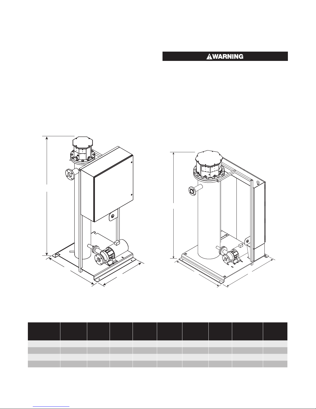
H
H
D
W
W
D
MOS 50-150 kW Unit (Front View) MOS 175-500 kW Unit (Rear View)
Unit Proportions
2
TDH
Motor
(Ft.)
130 10
HP
Inlet/Outlet
Connection
3
ANSI
3”, 150#
System
Capacity
(Gal.)
3
Unit Size
Dry
Weight
(Lbs.)
Width
(In.)
Depth
(In.)
Height
(In.)
Flow
1
Rate
2
Pressure
GPM
50 & 75 kW 900 36 42 96 80 130 5 2”, 150# 24
100-150 kW 1400 36 42 96 120 130 7.5 3”, 150# 35
175-300 kW 2600 48 54 96 200 130 10 3”, 150# 65
350-500 kW 3500 48 54 96 200
1
650˚F Option will add 8” to overall height.
2
Refer to pump graph for full operating range
3
Option for 300 GPM 20HP pump with 4”, 150# inlet/outlet
3
85
2

Fluid Compatibility
This system is NOT for use with water, ethylene
glycol and water mixture or some of the synthetic heat transfer fluids.
To avoid possible damage to the heaters do not
energize the heater unless the system is filled
with fluid.
Read manufacturer’s technical bulletins and instructions carefully. Some heat transfer fluids may ignite or
burn spontaneously if not properly used.
If you are not sure you are using an accepted heat
transfer fluid, check with fluid manufacturer.
Unit Installation
Note: When installing system, allow sufficient room to
remove heating bundle.
Hydraulics
Note: The MOS systems should be mounted so the
control box does not fall in direct sunlight.
The bed plate should be mounted on a level, solid
foundation and bolted down.
DO NOT mix heat transfer fluids unless authorized and
approved by the fluid manufacturer. All heat transfer
fluids are not compatible with each other, whether
made by the same manufacturer or a different manufacturer. If you plan to switch fluids, check with the fluid
manufacturer to determine the following.
A. Is the new fluid compatible with the old?
B. What is the recommended cleaning method to re-
move the old fluid, its sludge, or any deposits remaining in the system?
C. Does the fluid manufacturer have a reclaiming ser-
vice for used fluid? Do they have recommended
procedure for disposal of used or old fluid?
1. Allow at least 1 foot or more around unit for proper
maintenance,
2. Unit is designed for 104˚F (40˚C) maximum operating environment.
3. Unit will be operating at elevated temperatures.
Proper care must be provided to ensure personnel
safety.
Piping Installation
1. The pipe size should be the same as the system
piping connections. All piping must be supported
so the pump is not carrying any of the pipe weight.
If these instructions are not followed, distortion in
the pump may cause unnecessary wear and faulty
operation.
2. The piping of the entire system should be arranged
to minimize pockets where air may be trapped.
Manual air vents or bleeder valves should be provided in the system where air pockets may occur,
or where the flow of fluid may drop.
3. Piping should be properly supported so pump can
be removed without changing the position of the
piping. If piping moves when the pump is removed,
pump malfunction is probably due to stresses and
twisting caused by the piping. These stresses will
multiply where the system is hot due to thermal expansion.
4. If there is a high differential pressure between the
inlet and outlet of the heat transfer system at operating temperature, this is probably due to a piping
restriction. A continuing high differential pressure
can cause excessive wear on the pump and pump
stuffing box packing or mechanical seal and will
eventually cause premature failure of the pump.
The major causes of restrictions are:
a. Inlet and outlet pipes smaller than provided on
the system.
b. Piping many processes in series with one anoth-
er. To reduce the pressure drop of the system,
equipment should be re-piped in balanced parallel flow.
DO provide for expansion and contraction of process
piping and connections to the system. Piping strains
can cause pump and motor misalignment, excessive
wear on pump body, bearings and stuffing box packing
or mechanical seal and will eventually cause failure of
the pump and system.
DO provide sufficient cross sectional area in the process piping connections equivalent to the system
pipes. In order to prevent undue pressure drop, maximum velocity in all piping should be less than 10 feet
per second.
DO check all vent tubes, purge valves, and bypass relief valves at least once a month. All heat transfer oils
oxidize in the presence of air and sludge can block critical piping. Blocked vent tubes may cause excessive
system pressures and/or an explosion.
DO retighten all bolted connections and joints at operating temperature. Joints will expand and leak as they
get hot. Check all threaded connections on controls,
gauges, etc. for leaks.
3
 Loading...