

Page 1
Installation and
Operating Instructions
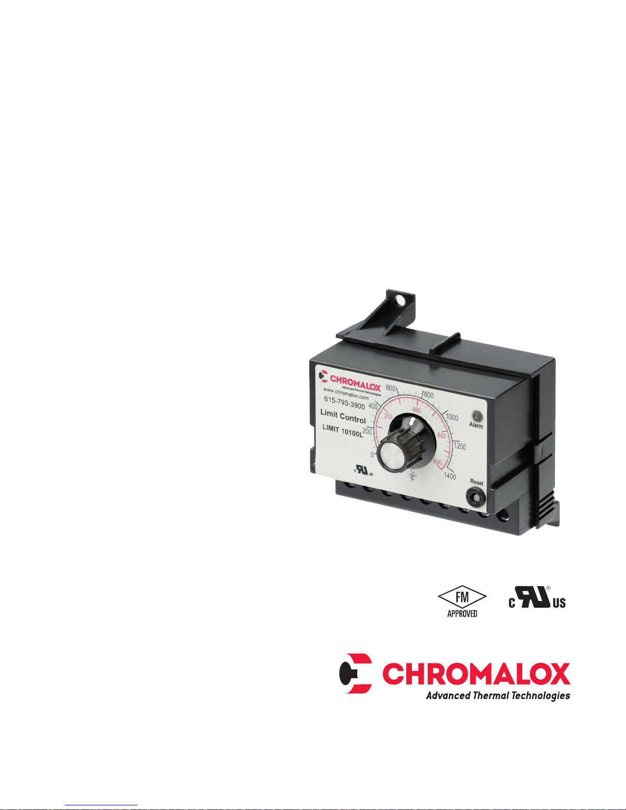
LIMIT
Temperature Controller
PK523-2
0037-75551
September 2018
1
Page 2
LIMIT Temperature Control
The LIMIT protects expensive heaters and sensitive
materials from damaging over temperature conditions.
It is designed for industrial and commercial applications
that require high temperature protection.
The LIMIT features a Form C latching, manually resettable relay output that de-energizes whenever the sensed
temperature exceeds the set point temperature.
The DIN Rail mounting feature allows quick installation
without drilling or extra hardware. Slots are also provided for direct panel mounting.
Two methods are provided to reset an alarm condition.
(1) The Limit alarm has a reset pushbutton on the unit
and (2) reset terminals are provided for resetting the
alarm from a remote pushbutton.
Mounting
ELECTRIC SHOCK HAZARD. Read and understand
all instructions before installing, servicing or operating LIMIT controller. Failure to do so could result
in personal injury or property damage.
The Heating system designer is responsible for the
safety of the equipment and must determine the
suitability of this temperature LIMIT controller with
other electric heating equipment. Where the conse
quences of failure could result in personal injury or
property damage, back-up controls are essential.
-
The LIMIT can be surface mounted or DIN rail mounted. It can be mounted to any suitable flat surface using
two #6 screws (not supplied). To install simply position
the top set of rear clips over the top of the DIN rail.
Then swing the bottom of the controller toward the rail
applying pressure until the lower clips snap on to the
bottom of the DIN rail. To remove apply pressure to the
top of the controller’s base and move the bottom of the
controller toward you. Then lift the top of the controller
off the upper DIN rail. The housing rating is NEMA 1.
This controller must be mounted in an enclosure
suitable for protection against normally expected
operation environments and to minimize unauthorized tampering with the limit settings.
FIRE/EXPOSION HAZARD. This heater is not intended for use in hazardous atmospheres where flammable vapors, gases, liquids or other combustible
atmospheres are present as defined in the National
Electrical Code. Failure to comply can result in personal injury or property damage.
2
Page 3

Dimensions
*Each LIMIT requires its own contact input for reset. A single contact input cannot be used to reset multiple LIMITS.
Operation
The set point temperature is adjustable by turning the
integral dial. If the set point is exceeded, contacts 4
and 5 will open. It will remain in this state until the temperature drops below the set point and the controller is
manually reset. Manual reset can be accomplished by
one of the following means:
a) Press the “reset button”.
b) A momentary switch closure between terminals 8
and 9.
c) Interrupt power to the control.
Troubleshooting
Experience has proven that many control problems
are not caused by a defective instrument. Some of the
common causes of failure are broken sensors, open
fuses and poor wire connections. If these points have
been checked and the control still does not function,
it is suggested that the instrument be returned for inspection. Use adequate packing materials to prevent
damage in shipment.
Maintenance
No specific maintenance is required. However, it is
recommended that all wiring be checked periodically
for loose connections and damaged wires. Disconnect
power to the panel before any maintenance is performed. Check wires and tighten connections.
ELECTRIC SHOCK HAZARD. Disconnect all power before
installing or servicing LIMIT controller. Failure to do so
could result in personal injury or property damage.
Custom Controllers
Custom temperature ranges and fixed set point units
are available to meet your specific application needs.
3
Page 4
Control
Contactor
Wiring
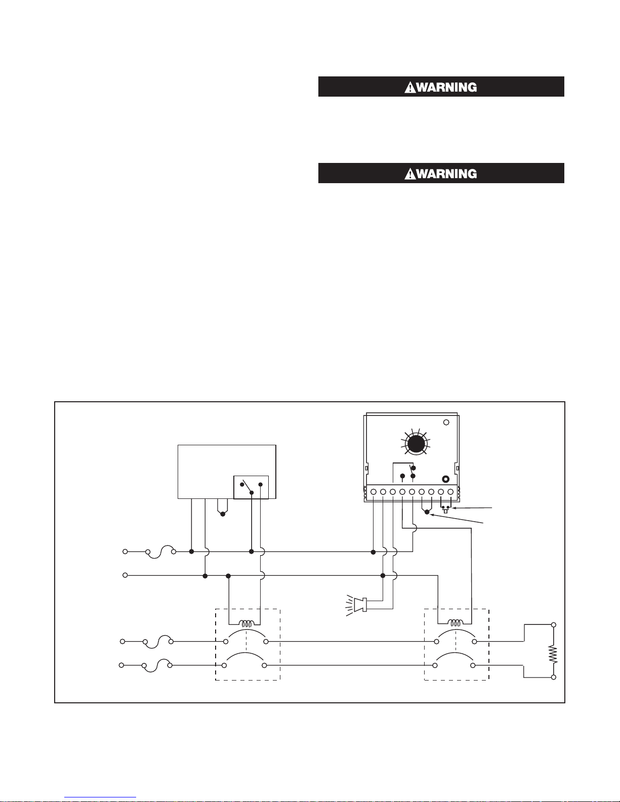
Carefully follow the terminal diagram pictured on the
controller’s housing and shown above. The power and
load wiring should be 18 AWG or larger size. Be sure to
observe that the ratings for voltage and current are not
exceeded. All local and national electrical codes must
be followed.
Use only the sensor type as indicated on the control
and maintain correct polarity. THE RED THERMOCOUPLE LEAD ALWAYS CONNECTS TO THE NEGATIVE (–)
TERMINAL. To reduce electrical noise, the thermocouple wire must be isolated from any power or heater wiring. Shielded thermocouple wire may be necessary in
high noise environments or when lead lengths exceed
10 feet (3 m). Thermocouples are tip sensitive and must
be in good mechanical contact with the load.
The remote reset terminals allow for a remote pushbutton (on the panel door) to reset the LIMIT alarm. If
multiple units are mounted in a panel, the remote reset
terminals cannot be wired in parallel. The remote pushbutton needs a separate contact block for each LIMIT.
A single contact input cannot be used to reset multiple
LIMITs.
ELECTRIC SHOCK HAZARD. Any installation involving
LIMIT temperature controllers must be performed by
a qualified person and must be effectively grounded
in accordance with the National Electrical Code to
eliminate shock hazard. Failure to do so could result
in personal injury or property damage.
ELECTRIC SHOCK HAZARD. Disconnect all power
before installing or servicing LIMIT controller. Failure to do so could result in personal injury or property damage.
Typical Wiring Diagram
Primary
Temperature
Control
120VAC
Control
Fuse
H
5A
120V
Control
Power
N
Heater Power
1 or 3 Phase
Heater
Fuses
T/C
or
RTD
NC
C
Coil
Primary
NO
Optional Alarm
or Warning
Lamp
LIMIT-10100L
234
1
˚F/˚C
NC
NO
C
+
56789
Alarm
Reset
–
Optional N.O.
Remote Reset
Switch
T/C or RTD
Coil
Heater(s)
Limit
4
Page 5
Specifications
Power Input: ........................120VAC or 24VAC ±15%,
50/60Hz, 3VA max. standard
Control Output: .......SPDT Relay rated 3.8 Amps Res.
and 1.5 Amps Pilot Duty 120 VAC.
100,000 cycles.
Control Mode: ................. Latching with Manual Reset
or power off.
Reset Function: ........... Integral reset switch standard;
terminals available for
optional remote reset switch
Set Point Adjustment: ........Local SP dial adjustment.
Compensation (TC only): ......Automatic cold junction
compensation.
Control Stability: .............................Typically less than
±5μV/°F ambient and 0.1% of
SPAN/% rated line voltage.
Set Point Accuracy: ...................±3% of FS maximum
at 25°C and rated line voltage.
Sensor Break Protection: ..... Contacts 4 & 5 open for
thermocouple or RTD break.
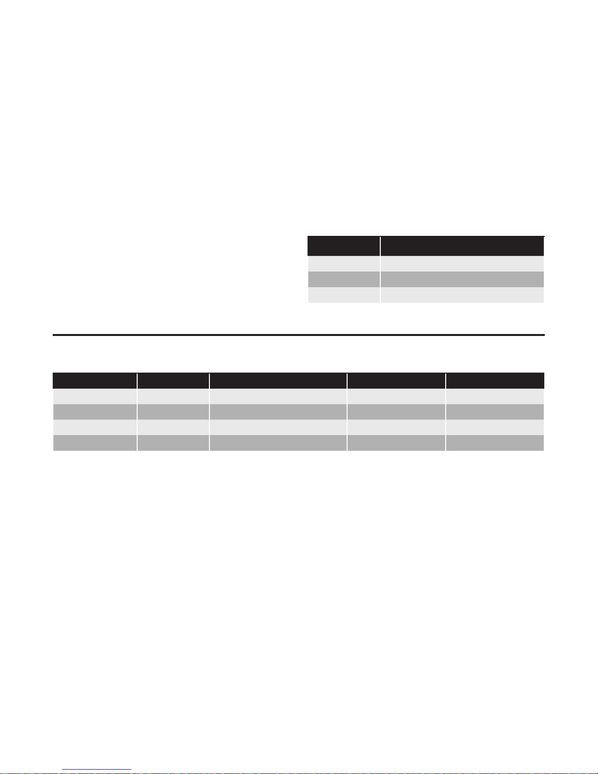
Ordering Information
Ambient Operating Temperature:................. 0 - 55°C
(32 - 131°F).
Noise Rejection: ................ Common Mode Rejection
60dB Series Mode Rejection 120dB
Trip Inidcator: .... LED Illuminates when controller trips
Mechanical
Enclosure Material: .......................... Noryl, Black color.
Field Terminations: ......................Screw Terminals with
wire clamping plates and
touch safe shield.
Mounting: ............ 35mm DIN rail or surface mounting.
Sensor Inputs
Sensor Range
J T/C 0 to 1400°F, -20 to 760°C
K T/C 0 to 2300˚F, -20 to 1260°C
RTD 0-850°F / -20˚C - 455˚C
Model PCN Temperature Range Input Type Input Power
LIMIT-10100L 309200 0-1400°F / -20˚C - 760˚C J T/C 120 Vac
LIMIT-10200L 309219 0-2300°F / -20˚C - 1260˚C K T/C 120 Vac
LIMIT-10400L 309243 0-850°F / -20˚C - 455˚C RTD 120 Vac
LIMIT-10101L 309235 0-1400°F / -20˚C - 760˚C J T/C 24 Vac
5
Page 6

Limited Warranty:
Please refer to the Chromalox limited warranty applicable to this product at
http://www.chromalox.com/customer-service/policies/termsofsale.aspx.
Chromalox
103 Gamma Drive
Pittsburgh, PA 15238
(412) 967-3800
www.chromalox.com
© 2018 Chromalox, Inc. All rights reserved.
6
 Loading...