

Page 1
© 2010 Chromalox®, Inc.
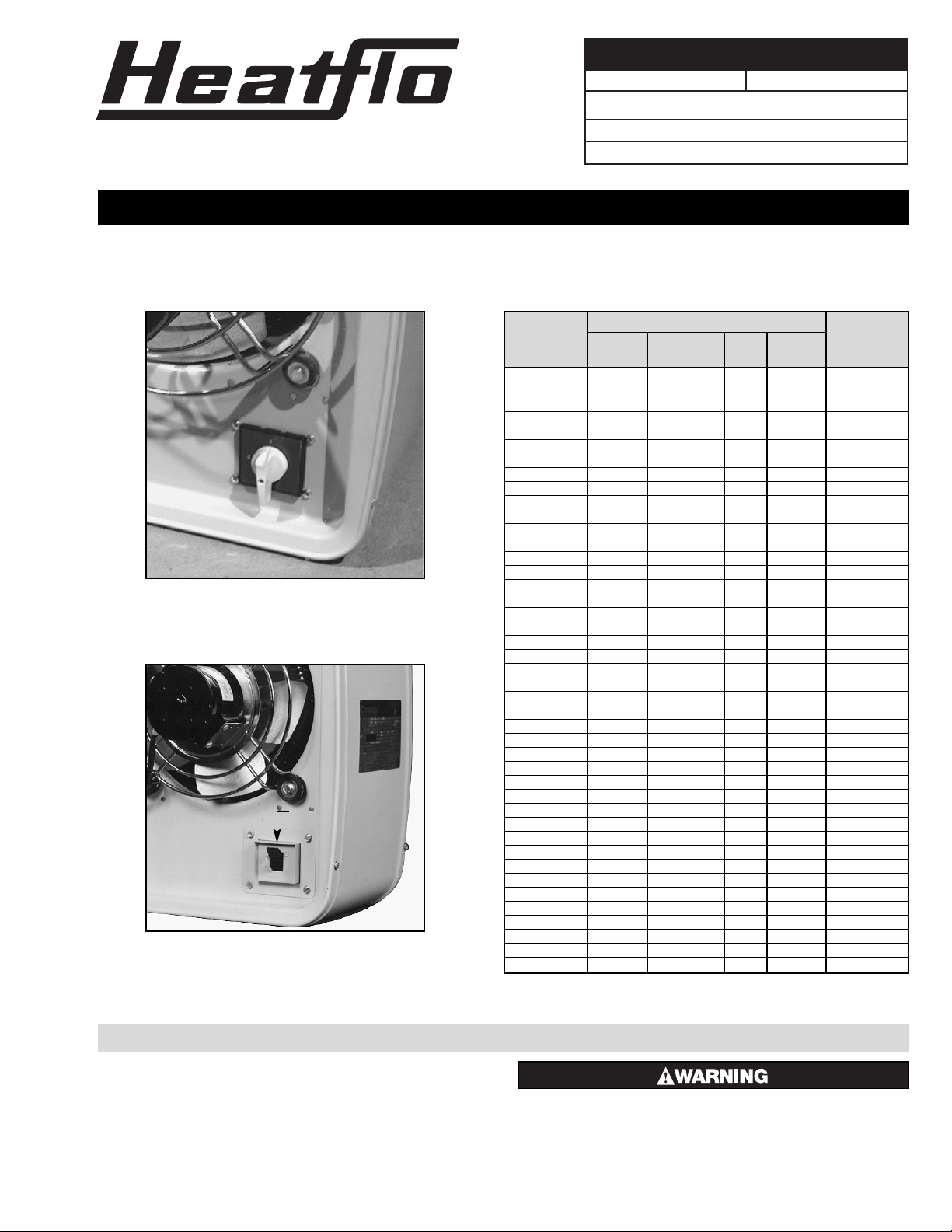
Power Disconnect Switch Kits
Electrical Data (60Hz)
Standard
Model Contactor
Volts kW Phase Amps
Rating (Qty.)
KUH-C-02-81 208 2.667 1 12.8
KUH-C-02-21 208/240 2/2.667 1 11.1*
KUH-C-02-71 277 2.667 1 9.6
KUH-C-04-81
208 4
1 19.2
KUH-C-04-83 3 11.2 30A (1)
KUH-C-04-21
208/240 3/4
1 16.7*
KUH-C-04-23 3 9.6* 30A (1)
KUH-C-04-71 277 4 1 14.5
KUH-C-04-43 480 4 3 4.8 30A (1)
KUH-C-05-81
208 5
1 24.0
KUH-C-05-83 3 13.8 30A (1)
KUH-C-05-21
208/240 3.75/5
1 20.8*
KUH-C-05-23 3 12.1* 30A (1)
KUH-C-05-71 277 5 1 18.2
KUH-C-05-43 480 5 3 6.0 30A (1)
KUH-C-07-81
208 7.5
1 36.1 50A (1)
KUH-C-07-83 3 20.9 30A (1)
KUH-C-07-21
208/240 5.625/7.5
1 31.1* 30A (1)
KUH-C-07-23 3 18.1* 30A (1)
KUH-C-07-71 277 7.5 1 27.2 30A (1)
KUH-C-07-43 480 7.5 3 9.0 30A (1)
KUH-C-10-81
208 10
1 48.0 50A (1)
KUH-C-10-83 3 27.8 30A (1)
KUH-C-10-21
208/240 7.5/10
1 41.7* 30A (1)
KUH-C-10-23 3 24.0* 30A (1)
KUH-C-10-43 480 10 3 12.0 30A (1)
KUH-C-12-83 208 12.5 3 34.8 50A (1)
KUH-C-12-23 208/240 9.375/12.5 3 30.1* 50A (1)
KUH-C-12-43 480 12.5 3 15.1 30A (1)
KUH-C-15-83 208 15 3 41.8 50A (1)
KUH-C-15-23 208/240 11.25/15 3 36.2* 50A (1)
KUH-C-15-43 480 15 3 18.1 30A (1)
KUH-C-20-23 208/240 15/20 3 48.0* 50A (1)
KUH-C-20-43 480 20 3 24.0 30A (1)
KUH-C-25-43 480 25 3 30.0 50A (1)
KUH-C-30-83 208 30 3 83.4 50A (2)
KUH-C-30-23 208/240 22.5/30 3 72.2* 50A (2)
KUH-C-30-43 480 30 3 36.1 30A (2)
KUH-C-35-23 208/240 26.25/35 3 84.3* 50A (2)
KUH-C-35-43 480 35 3 42.1 30A (2)
KUH-C-40-23 208/240 30/40 3 96.0* 50A (2)
KUH-C-40-43 480 40 3 48.0 30A (2)
KUH-C-45-43 480 45 3 54.1 30A (2)
Specifications – Table A
GENERAL
The following procedure contains instructions for installing
Power Disconnect Switches.
ELECTRIC SHOCK HAZARD. Disconnect all power
before installing disconnect switch. Failure to do
so could result in personal injury or property damage. Disconnect switch must be installed by a
qualified person in accordance with the National
Electrical Code, NFPA 70.
*208V amperage is 86% of 240V value.
®
DIVISION 4 SECTION
KUH
SALES
REFERENCE
DATE
SERVICE REFERENCE
PF486-3
161-303476-001
AUGUST, 2004
(Supersedes PF486-2)
INSTALLATION INSTRUCTIONS AND RENEWAL PARTS IDENTIFICATION
3 Pole
Model Rating PCN
KDS-1 50 Amp for units rated 480V and less 304434
40 Amp for units rated 500V to 600V
3 Pole 600 V Rating
Model Rating PCN
KDS-2 80 Amp 304442
KDS-3 100 Amp 304450
Power Disconnect Switch
for Field Installation
Page 2
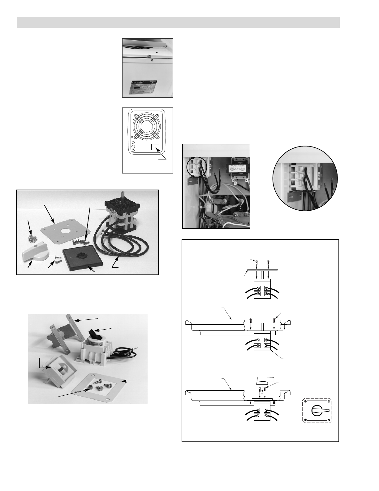
Mounting Bracket
Plastic
Bezel
Mounting Plate
Hardware
(Self Tapping)
Mounting Plate
Cover
INSTALLATION
1. The amperage rating of the disconnect
must be equal to or greater than the
amperage rating on Table A and as
marked on the nameplate located on the
bottom access door (Figure 1).
2. The power disconnect kit is to be installed
in the rectangular knockout located in the
bottom right corner on the back of the
heater (Figure 2). The knockout can be
removed using a hammer and chisel or
other appropriate means.
For easier access to terminal screws to
wire pigtail leads supplied on the heater, it
is suggested that these connections be
made before installing. See Wiring
Instructions.
3. The disconnect switch assembly (Figures
3 or 4) consists of a mounting bracket,
disconnect switch, mounting plate cover
and self tapping screws.
4. The Disconnect switch, with its mount-ing bracket should be
inserted into the heater cabinet by opening the bottom service
door and positioned behind the opening created in Step 2 (see
Figure 5).
KDS–1
5. The disconnect switch, with its mounting plate should be inserted
into the heater cabinet by opening the bottom service door and
positioned behind the opening created in step 2 (see Figure 5).
6. Insert the four self tapping screws into the four holes in the rear
panel. They should engage the holes in the mounting plate and
then be tightened until they are secure (see Figure 6).
7. Mount the switch faceplate to the switch using the two provided
screws. Mount with the “OFF” position to “0” to the left and the
on position “1” to the top. Slide the handle over the shaft and
tighten the screw to secure.
Figure 2
Figure 4
80 and 100 Amp Kit — KDS-2 and KDS-3
The disconnect switch has a bracket for mounting the switch.
Figure 5
Knockout
REAR CASE
REAR CASE
0
1
(ON)
(OFF)
(2) 6-20 x 1/2 SCREWS
MOUNT FACEPLATE WITH "ON"
POSITION TO TOP OF HEATER
MOUNT SWITCH ASSEMBLY
ONTO REAR CASE OF HEATER
(4) 8-32 SCREWS
(4) 8-18 X 1/2 SCREWS
COVER PLATE
Figure 6 – KDS-1
Figure 1
Figure 3
40 and 50 Amp Kits — KDS-1
The disconnect switch has a bracket for mounting the switch.
Disconnect Switch
Pigtail Leads
Handle
Faceplate
(4) 8-18 x 1/2
(4) 8-32 x 1/2
(2) 6-20 x 1/2
Mounting Plate Cover
2
Page 3
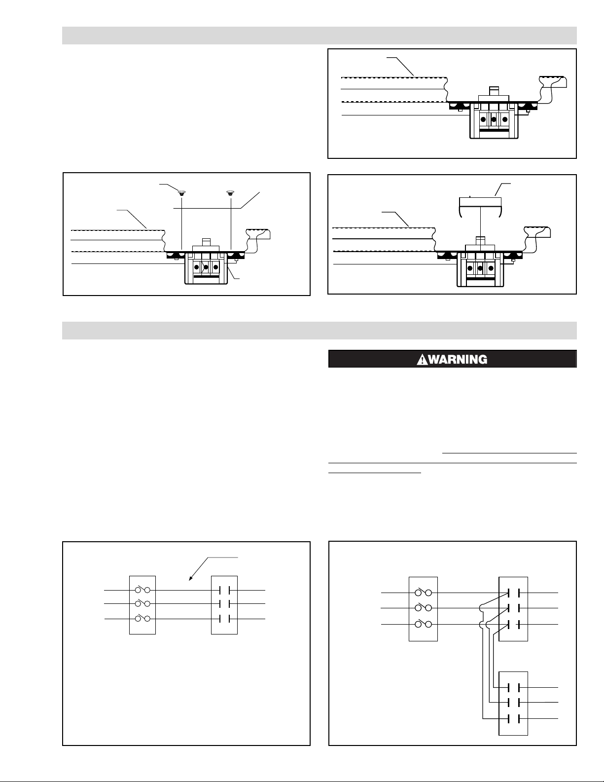
L1
L2
L3
AL1
AL2
AL3
Power
Disconnect
Switch Contactor
To
Power
Supply
See
Note 2
See Notes
Pigtail
Leads
L1
L2
L3
AL1
AL2
AL3
Power
Disconnect
Switch
Contactor (1)
To
Power
Supply
Contactor (2)
Figure 10
KUH-02 through KUH-25
Power Disconnect Switch
Figure 11
Notes:
1. This illustration shows wiring hook up for three phase
service. Remove lead wires marked L2 and AL2 when
using one phase power service.
2. For units without contactors, disconnect switch is to
be wired to lead wires on heater power.
3. Use copper supply wire only with this switch.
KUH-30 through KUH-45 units with 2 contactors
where the total load does not exceed 48 Amps.
WIRING
INSTALLATION (Cont’d)
POWER DISCONNECT SWITCH (Available as a kit or
factory installed option.) (KDS-1)This switch disconnects the
power to power leads when the handle is rotated to the “0” position (left). The power is on when the switch handle is rotated to
the “1” position (top) position. (KDS-2 and KDS-3) This switch
disconnects power to the power leads when the handle is placed
in its full lower position. The power is on when the switch handle
is in its full upper position.
1. Use the three pigtail leads supplied with kit (40 & 80 Amp) when
connecting to the power line.
a. Use No. 4GA Copper conductor wire only for 100 Amp dis-
connect when wiring to the power line.
2. The power disconnect wiring to the heater is to be made using the
pigtail leads supplied on the heaters up to and including 25 kW.
On larger heaters, the installer should supply 105˚C type AWM
600V wire.
ELECTRIC SHOCK HAZARD. Disconnect all power
before installing disconnect switch. Failure to do
so could result in personal injury or property damage. Disconnect switch must be installed by a
qualified person and must be effectively grounded
in accordance with the National Electrical Code,
NFPA 70.
For future replacement parts, the model number should be modi
fied on the nameplate to show that a disconnect kit has been field
installed on the heater. A label kit (see Figure 14) (P/N 170302788-002) has been included in the plastic envelope located in
the disconnect kit. Cut off the appropriate number for the size disconnect being installed (40 Amp = 1; 80 Amp = 2; 100 Amp = 3).
The label has a pressure sensitive adhesive back so that the number can be placed over the “0” as shown in Figure 14.
KDS–2 and KDS – 3
8. The cover plate should be placed over the rectangular opening
with its four mounting holes lined up with the four holes in the
cabinet and the four holes in the mounting bracket (see Figure 7).
9. Insert the four self tapping screws into the four holes until they
engage the holes in the mounting bracket and tighten until they
are secure (see Figure 8).
10. Place plastic bezel over the installed switch and push towards the
switch until the tabs snap into place (see Figure 9).
Rear Case
Cover Plate
(4) 8-32 Screws
Mount Switch Assembly
Onto Rear Case of Heater
Figure 7
Figure 8
Figure 9
Rear Case
Switch Assembly Mounted to Rear Case
Rear Case
Snap Plastic Housing
Into Place
3
Page 4
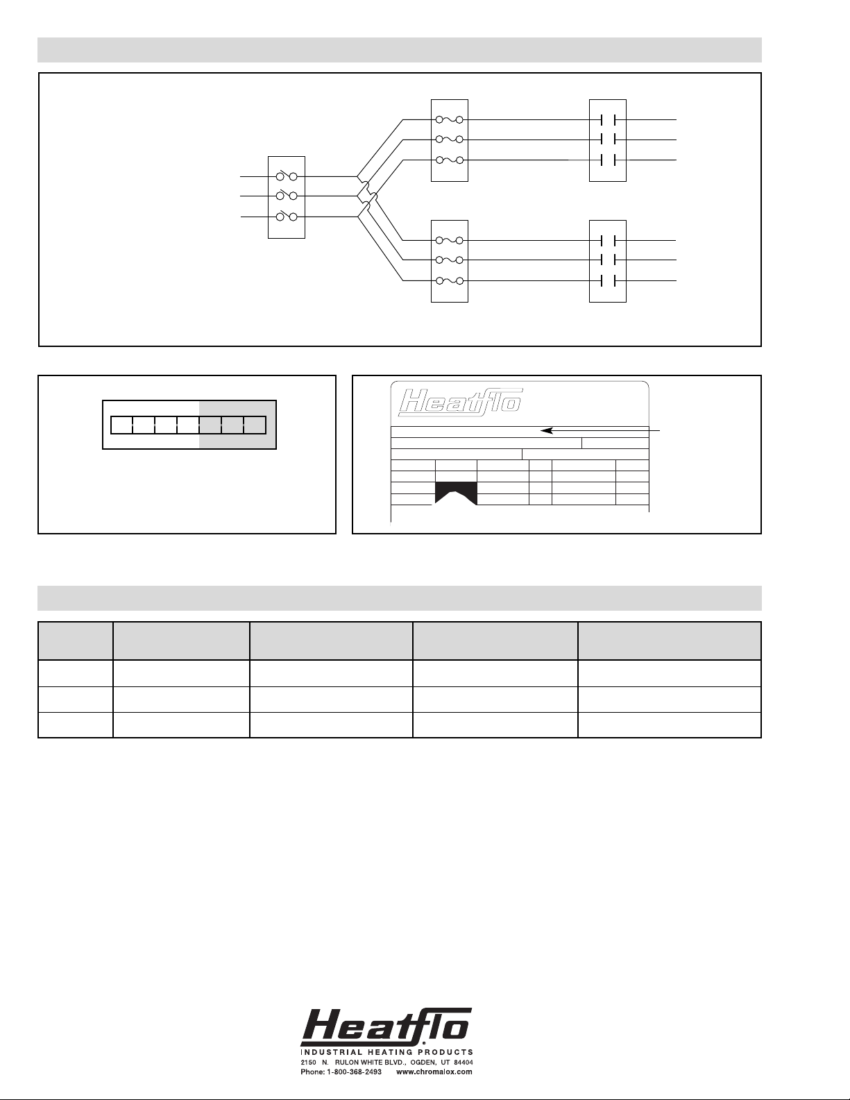
REPLACEMENT PARTS LIST
WIRING (Cont’d)
Disconnect
Size Kit Model # Disconnect Cover Plate Mounting Bracket
50 Amp KDS-1 292-303472-001 220-303485-010
80 Amp KDS-2 292-303472-002 220-303485-003 220-303484-003
100 Amp KDS-3 292-303472-008 220-303485-003 220-303484-003
Figure 12
Figure 13 — Pressure Sensitive Label
CATALOG NO. KUH-C- 07 - 43 - 32 - 00 - 0
MFG. PART NO. 004 - 303375 - 265
MIN. CIRC. CAP. AMPS MAX. CIRC. FUSE AMPS
RATING KW V.A.C. ONLY PH AMPS HZ
HEATER 7.5 480V 3 9.0 60
MOTOR 480V 1 .28 60
CONT. CKT. 120V 1 10 60
SERIAL NO. P/N 196-057744-002
V.A.
MAX.
DATE
CODE
®
Figure 14 — Nameplate
Place Number at
the end of the
Catalog Number
Number 1, 2 or 3 designates the Disconnect Code for Kit.
1 = 40 Amp; 2 = 80 Amp; 3 = 100 Amp
-42 -43 -44 -45 -1 -2 -3
L1
L2
L3
AL1
AL2
AL3
Power
Disconnect
Switch
To
Power
Supply
Fuse Block (1)
Fuse Block (2)
Contactor (1)
Contactor (2)
KUH-30 through KUH-45 units with 2 contactors
where the total load exceeds 48 Amp and subcircuit fuse blocks are provided.
Limited Warranty:
Please refer to the Chromalox limited warranty applicable to this product at
http://www.chromalox.com/customer-service/policies/termsofsale.aspx.
 Loading...