

Page 1
Installation Manual & Set-Up Guide
Ordinary Area
ITAS Ambient Sensing Control Panel
ITAS-EXT Ambient Sensing Extender Control Panel
ITLS Line Sensing Control Panel
ITLS-EXT Line Sensing Extender Control Panel
Hazardous Area
ITASC1D2 Ambient Sensing Control Panel
ITASC1D2-EXT Ambient Sensing Extender Control Panel
ITLS C1D2 Line Sensing Control Panel
ITLS C1D2-EXT Line Sensing Extender Control Panel
PK497-5
0037-75514
June 2018
1
Page 2
Safety Precautions
IMPORTANT SAFEGUARDS
Throughout the IntelliTrace® Setup Guide, these symbols will alert you to potential hazards. Safety precautions should always be followed to reduce the risk of
fire, electrical shock, injury and even death to persons.
Please read all instructions before operating your
IntelliTrace® ITLS, ITAS, ITLS-EXT or ITAS-EXT Control
Panel.
WARNING
HIGH VOLTAGE is used in the operation of this equipment; DEATH ON
CONTACT may result if personnel fail
to observe safety precautions.
Learn the areas containing high-voltage connections when installing or
operating this equipment.
To avoid electrical shock or injury, always remove power before servicing a circuit. Personnel working with
or near high voltages should be familiar with modern
methods of resuscitation. Contact an area supervisor
or safety personnel for more information.
WARNING
ELECTRIC SHOCK HAZARD
Any installation involving control
equipment must be performed by a
qualified person and must be effectively grounded in accordance with
the National Electrical Code to eliminate shock hazard.
Be careful not to contact high-voltage connections when installing or
operating this equipment.
Before working inside the equipment,
turn power off and ground all points
of high potential before touching
them.
ii
Page 3

Table of Contents
Contents Page Number
Safety Precautions .................................................................................................................................................ii
Table of Contents .................................................................................................................................................iii
Introduction ............................................................................................................................................................ 1
Model Overview ..................................................................................................................................................... 2
Theory of Operation .............................................................................................................................................. 3
Types of Sensing Control ..................................................................................................................................... 4
Pre-Service Storage .............................................................................................................................................. 5
Before Powering Up ............................................................................................................................................. 5
General Panel Notes ............................................................................................................................................ 6
Installation ............................................................................................................................................................. 7
Main Menu Screen ............................................................................................................................................... 8
Temp Setup Menu.. .............................................................................................................................................. 9
Security Levels & Password Screen ................................................................................................................. 10
Temp Setup Menu (Cont.) ................................................................................................................................. 11
Apply Settings Globally .................................................................................................................................... 13
Soft Start Feature .............................................................................................................................................. 13
Load Setup Menu .............................................................................................................................................. 14
Tuning Menu ......................................................................................................................................................... 16
Control Modes: ON/OFF, Autotune & PID ......................................................................................................... 17
Sensor Mapping ................................................................................................................................................ 18
System Properties ............................................................................................................................................. 19
Auto Cycle Feature ............................................................................................................................................ 20
Communications ............................................................................................................................................... 21
Remote Monitoring & System Management ................................................................................................... 21
Alarm Log ........................................................................................................................................................... 22
Active Alarms ..................................................................................................................................................... 23
Clearing Alarms ................................................................................................................................................ 23
Alarm Troubleshooting ..................................................................................................................................... 24
Extension Panels – Connection & Considerations ......................................................................................... 25
Connecting the Extension panel to the Main Panel ......................................................................................... 25
Extension Panel Considerations ....................................................................................................................... 25
Wireless Temperature Sensing ......................................................................................................................... 26
Appendix A ......................................................................................................................................................... 37
Panel Specifications ......................................................................................................................................... 37
Default Settings ................................................................................................................................................ 38
Appendix B ......................................................................................................................................................... 44
ModBus Specification ...................................................................................................................................... 44
Service Contact Information .......................................................................................................................... 106
iii
Page 4

Page 5

Introduction
For nearly 100 years, customers have relied upon Chromalox for premiere quality and innovative solutions for
industrial heating applications. Chromalox manufactures the world’s largest and broadest line of electric heat and
control products.
The IntelliTrace® ITLS & ITAS Series Multiple Circuit Panels and Extender Panels are a complete temperature
control and system management solution for electrical heat trace applications. They are designed for industrial
applications in Hazardous (Class I, Division 2) or Non-Hazardous environments.
IntelliTrace® provides the user with an easy to navigate touch-screen interface, system parameter monitoring, off
duty preventative maintenance, application flexibility and system customization.
The ITAS and ITASC1D2 provide Ambient Sensing control while the ITLS and ITLSC1D2 provide either Line Sensing control or a hybrid of both Line and Ambient Sensing control.
IntelliTrace® Features:
• 40 Amps/Circuit @ 100 – 600 VAC
• SSR Output Power Control
• 2 to 72 Circuit
• Large Touch Screen HMI
• Integral Control Panel and Circuit Breaker Distribution (non-hazardous areas)
• 1-pole or 2-pole Designs
• Soft Start, On/Off, PID and Manual (Hand) Control
• Modbus RTU/RS485 or TCP/Ethernet Communications
• Full Monitoring & Alarms (Lo/Hi Current & Temperature, Sensor, Transmitter Battery, Communications & GFEP)
• Hazardous (Class I, Division 2) and Non Hazardous Environments
• NEMA 4 Enclosure (Optional NEMA 4X 304 SS)
• UL, cUL Listing (CE available)
Touch Screen Computer:
• 10” on 6 – 72 Circuit Systems and 7” On 2 – 8 Circuit Systems
• 2 or 6 Circuit Circuit Detail Displayed at a Time
• Quick Launch to any 2 or 6 Circuit Group Display
• Remote Desktop Monitoring
• Extremely Intuitive Navigation, User Setting and Operation
• Fully Customizable Circuit Naming and Parameter Programming
Options:
• Powerful and Flexible Sensor Mapping (ITLS, ITLSC1D2 only)
• Enclosure Heater
• Fully Integrated Wireless Temperature Sensing
• IntelliTrace® Supervisory Control (ISC) for Central Command of Multiple Systems
1
Page 6

Model Overview
The Chromalox line of IntelliTrace® Heat Trace Control
Panels provides a significant amount of application
and feature flexibility.
vide the flexibility for the owner to meet their process
expansion needs. Simply connect the Extension Panel
to its matching ITLS, ITLSC1D2 or ITAS, ITASC1D2
Base Panel and circuit capacity is seamlessly in-
The ITAS and ITASC1D2 are designed for Ambient
Sensing applications while the ITLS and ITLSC1D2 are
creased. The Extension Panels do not have a HMI, but
otherwise are identical.
designed for Line Sensing applications. Additionally,
the ITLS and ITLSC1D2 have the capability to function
as both a Line Sensing control panel and an Ambient
Sensing control panel should the Customizable Sensor
These panels are UL and cUL Listed for Ordinary (Non
Hazardous ITLS/ITAS) and Hazardous (Class I, Division
2 ITLS/ITAS C1D2) Environments. CE is available.
Mapping feature be selected.
Please see Table 1 below for applicable features and
The IntelliTrace® matching ITAS-EXT, ITASC1D2-EXT
capabilities by model type.
and ITLS-EXT, ITLSC1D2-EXT Extension Panels pro-
Table 1
ITLS
Standard Features/Capabilities
Ordinary, Non-Hazardous Area X n/a X n/a X n/a X n/a
Hazardous Area (Class I, Division 2) n/a X n/a X n/a X n/a X
7" Touch Screen HMI (2-4 Loop Versions) X X X X n/a n/a n/a n/a
10" Touch Screen HMI (6-48 Loop Versions)
40 Amps/Loop @ 100-600 VAC X X X X X X X X
Circuits 2, 4, 6, 8, 12, 18, 24, 30, 36, 42, 48 (Expandable to 72 with -EXT Panel)
SCR Control X X X X X X X X
NEMA 4 Enclosure X X X X X X X X
Integral Circuit Panel with Circuit Breakers X n/a X n/a X n/a X n/a
Soft Start Feature X X X X 1 1 1 1
Full Communications X X X X 1 1 1 1
Full Alarm Capabilities X X X X 1 1 1 1
Complete GFEP Monitoring & Alarms X X X X 1 1 1 1
Load Monitoring & Alarms X X X X 1 1 1 1
Sensor Mapping X X X X 1 1 1 1
UL, cUL Listing X X X X X X X X
ITLS
C1D2 ITAS
X X X X n/a n/a n/a n/a
Options
Enclosure Heater X X X X X X X X
Wireless Temperature Sensing X X X X 1 1 1 1
Main Breaker/Disconnect X n/a X n/a X n/a X n/a
Nema 4X 304 SS Enclosure X X X X X X X X
HMI Sunshield X X X X n/a n/a n/a n/a
Panel Weathersheild X X X X X X X X
Heater Power and RTD Terminal Blocks X X X X X X X X
Z-purge system X n/a X n/a X n/a X n/a
Panel Light (on separate breaker) X X X X X X X X
Powered Receptacle (on separate breaker) X X X X X X X X
Copper Ground Bar X X X X X X X X
CE available X X X X X X X X
X - Available as a standard or option for this model
1 - This feature is enabled when paired with matching base panel
n/a - This feature is not available for this model
ITAS
C1D2 ITLS-EXT
ITLS
C1D2-EXT ITAS-EXT
ITAS
C1D2-EXT
2
Page 7

Theory of Operation
The set-up of the individual and global circuit parameters is explained in the Temp/Load Set-up sections of this
manual. This Theory of Operation overview is intended to give a quick summary of how it all works together.
• Each circuit of the system may be enabled (active) or disabled (inactive). A disabled loop will have no
output and will not map into the common alarm. It will display “Circuit #” and “Disabled” text above
the process temperature. Alarms for disabled circuit will not be monitored or displayed on the screen.
• Each circuit of the system may use unique individual control parameters or the control parameters may
be alike. The Global Settings function facilitates this action.
• The GFEP and Load current are automatically and continuously being calculated. The horizontal orange
bar indicates the average output current for that circuit. The GFEP current value is not displayed on
the screen but its value is compared to the GFEP setpoint. A GFEP alarm condition will occur when
the GFEP current value exceeds the GFEP setpoint value.
• If a ground fault that exceeds the GFEP setpoint value is detected during normal operation and “Trip”
button on the Load Setpoints screen is checked, the output of the defective circuit is set to 0% and
that circuit goes into an alarm condition. If “Trip” button is not selected, the operation of that circuit
continues and that circuit goes into alarm condition. The GFEP alarm may be either Latching or NonLatching.
• During extended periods of time where the output of all circuits are off, such as during warmer seasons, the Auto Cycle feature may be engaged. This feature initiates power to each circuit and checks
for alarms. Each output is tested for one minute within the desired Auto Cycle Interval. The Auto Cycle
feature may be disabled by setting the Auto Cycle Interval time to “0 Hours”.
• To limit inrush current on the overall system, a proprietary Soft Start algorithm is applied during system start-up. This will ONLY occur while the operation mode is set to AUTO. The Soft Start program
will increment output % by 1% every 1 second until the desired temperature is reached or the output
% achieves 100%. After the Soft Start program completes its cycle, the Control Mode of the system
will either be PID or ON/OFF Control Mode, depending what was selected by the user. The Soft Start
Program will not function if the control mode is set to Manual.
• Centralized control of multiple ITAS or ITLS panels is accomplished via the ISC-IntelliTrace Supervisory
Controller.
3
Page 8

Types of Sensing Control
Ambient Sensing Control
Strict ambient-sensing control utilizes a thermostat or a simple electronic controller which senses the ambient temperature via an RTD, Thermocouple or Bulb & Capillary sensor. This is the simplest type of control as the heating
circuit is energized only when the ambient temperature drops below the setpoint of the controlling device. This is
also known as On/Off control. A relatively large temperature variation around the setpoint is anticipated. Mechanical thermostats are often employed due to their low cost and acceptable accuracy. Multiple heater circuits are
controlled by a singular ambient sensed temperature. This is the least efficient type of control and it is typically
limited to freeze-protection applications.
PASC - Proportional Ambient Sensing Control
Proportional ambient sensing control (PASC) utilizes an electronic controller which continuously compares ambient
temperature and the rate of the change of the ambient temperature to the desired temperature setpoint and regulates
the heater output power accordingly. The result is a smaller temperature variation around the desired setpoint and
a much smoother response to changing weather conditions. Like ambient sensing control, multiple heater circuits
are controlled by a singular ambient sensed temperature. PASC control is therefore significantly more energy efficient than ambient sensing control. PASC control can be employed in a variety of heat trace temperature control
applications but is typically used for freeze protection.
Line Sensing Control
Line sensing control is where each heated section of pipe (or heated surface area) is controlled independently of
other sections of pipe and therefore must have its own controller. Multiple sections of pipe may also be independently
controlled by an electronic multiple circuit control system. The control method may be either proportional or On/
Off control. Each section may have different setpoints and different allowances around the setpoint temperature.
Line sensing control is typically found in process temperature maintenance applications. These applications are
typically more critical and thus demand tighter temperature control. Electronic control is highly recommended over
thermostat control. Like PASC, the pipe surface temperature and the rate at which it is changing is continuously
compared to the setpoint temperature. The controller responds to these variations and regulates the heater output
power accordingly. Mission critical applications should only be managed by controllers which monitor all parameters
and present alarms both locally and remotely via communications or supervisory control means.
4
Page 9

Pre-Service Storage
If this equipment cannot be placed into service upon receipt, prevent damage caused by impact, harsh environmental
conditions, condensation or liquid ingress. Preferably store in a clean, dry, air conditioned, or ventilated building.
During storage, assemblies should be placed on a firm, level surface to prevent distortion.
Outdoor storage of indoor equipment is not recommended. The covering provided during shipment of indoor assemblies is NOT adequate for outdoor storage.
Cover the equipment to keep it free from dust, dirt, and corrosive elements. The covering must protect the assembly,
but permit adequate ventilation. Blocking placed between the roof of the equipment and the cover will help keep
covering material from restricting the air flow.
If the storage area is subject to humidity and significant temperature changes, energize the anti-condensation heaters provided in the equipment, or add heat from a separate source to prevent condensation inside the equipment.
The internal temperature must be at least 5˚C (9˚F) above the ambient.
If storage temperatures fall below 0°C (32°F), energize the internal equipment heaters provided, or add sufficient
heat from a separate source to keep the internal temperature of the panel to at least 0°C (32°F).
In areas with high humidity, inspect the equipment regularly, and add additional heat if necessary to keep the
equipment dry.
Remove all loose packing, documents, and flammable materials before energizing heating elements.
Heat from a separate source must be removed before the equipment is put into service.
WARNING: Care must be taken that integral control power transformers are not accidentally
back-fed from the heater circuits. Disconnect primary and secondary fuses.
Summer Standby Operation
If equipment is switched off during warm periods, and they are subject to humidity and significant temperature
changes, energize the anti-condensation heaters provided in the equipment, or add heat from a separate source to
prevent condensation inside the equipment. The internal temperature must be at least 5˚C (9˚F) above the ambient.
Before Powering Up
Chromalox takes great pride in knowing that we have provided to you a product of premium quality and workmanship. We have taken every precaution to ensure that your equipment arrives safe and secure.
However, vibration and temperature changes during shipping can cause some components to become loose.
Additionally, throughout the life span of this product, other environmental and application conditions may have
affected the mechanical and electrical continuity of several internal components. Therefore, for your safety and
overall product performance, please take the time to familiarize yourself with the MAINTENANCE, OPERATION,
AND INSTALLATION INSTRUCTIONS technical manual that was shipped with your panel.
Since it is not uncommon for electrical wiring and mechanical connections to become slightly loosened during
shipment, we ask that you pay particular attention to section 4-5.3 Wiring and Connections:
4-5.3 WIRING AND CONNECTIONS. Check wiring and connections as follows:
a. Inspect wiring for wear, fraying, chipping, nicks, and evidence of over-
heating. Repair minor defects with a good grade of electrical tape, or
replace if needed.
b. Inspect for loose electrical and mechanical connections. Tighten or
replace defective crimp-style lugs. Re-solder loose solder connections.
Tighten or replace all loose or missing hardware.
5
Page 10

General Panel Notes
1. This panel is designed to UL508A to facilitate NEC and CEC compliance, However it is the responsibility of
installer(s) and end user(s) to make sure that the installation wiring and all equipment, including this panel,
fulfill appropriate national and local electrical code requirements.
2. Incoming and outgoing branch circuit conductors may not be protected by fuses or breakers in this panel.
Consult appropriate national and local electrical codes and device specifications for selective coordination.
3. Protection relays must be set on site according to the requirements of the site engineer’s protection study.
Low-level ground fault protection, if required, should be provided.
4. Consult all applicable instruction manuals.
5. Customer interlocks are provided for use of external shutdown device(s). Interlocks require contacts that open
to trip or shutdown.
6. Contacts are shown in the de-energized state. Controller contacts shown on electrical schematics are internal
to the controller. Most of these contacts are programmable to suit the mode of operation. Consult the appropriate user manual(s).
7. Dashed lines indicate user field wiring connections.
8. The panel installer must ground the panel according to appropriate national and local electrical code requirements.
9. Conduit openings in enclosure are to be user installed, sized and located as required. Hubs or fittings must be
of the same environmental rating as the enclosure to maintain integrity.
10. Unless fitted with an HMI sun sheild, do not place this equipment in direct sunlight.
11. Unless panel is properlly equipped with an enclosure heater for ambient temps below 0°C (32°F), the ambient
temperature outside this panel must be between 0°C (32°F) and 40°C (104°F).
12. If the panel cannot be placed into service upon receipt, an anticondensation heater must be used to prevent
condensation from forming inside the panel. This heater can be user supplied or factory supplied but must be
used to prevent damage to the panel.
13. Dimensions are for reference only, and are nominal unless otherwise specified.
6
Page 11
Installation
Heat Sink Considerations – Heat Dissipation
The Chromalox ITLS, ITLSC1D2, ITAS & ITASC1D2 Multiple Loop Heat Trace panels employ SSRs (Solid State
Relays) as a means to switch the heating load power. Inherently, SSRs produce heat when operating. This heat
is dissipated through the heat sinks which are typically mounted on the sides of the enclosures. These heat sinks
must be mounted such that the fins are vertically orientation in order to allow the heat sink to properly dissipate the
heat from the controller. The air flow around these heat sinks must in no way become restricted.
To maintain UL/cUL listing, the heat sinks must be inspected
prior to and during every season, or no more than every 12
months, to confirm that no debris or objects are in contact
with the heat sink. All debris must be removed from the
heat sink fins. High pressure blasts of clean, dry air or
other means which will not damage the fins are to be used
to dislodge all debris from the fins.
Servicing Heat Sinks
Adjacent Panel
or Wall
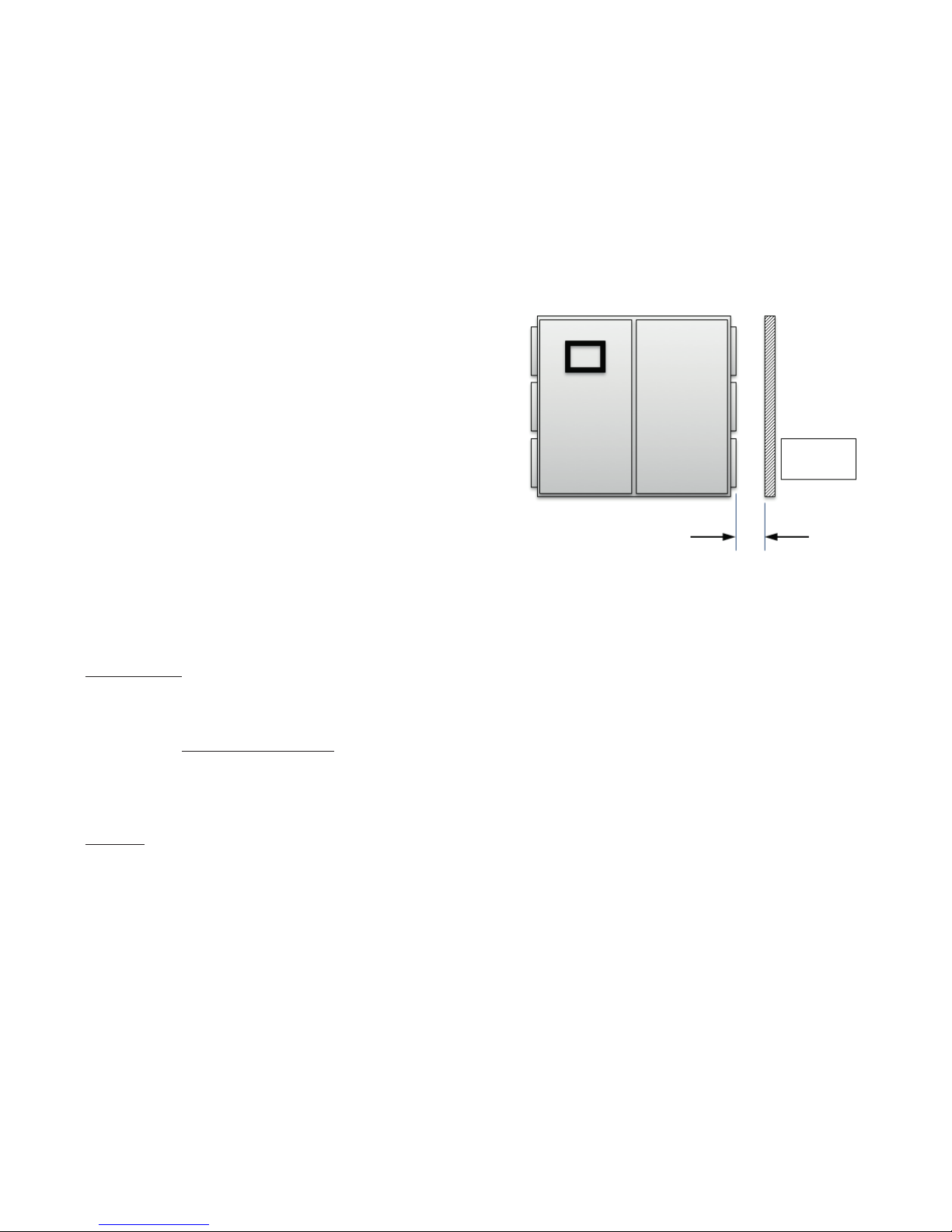
In the rare occurrence that the Power Board assembly, which
includes the Heat Sink, needs to be removed or inspected,
a minimum of 7 inches (18 cm) of clearance is needed to
externally withdraw the assembly from the enclosure.
7 Inches
(18 cm)
Outdoor Applications
Equipment protection from the environment must be carefully considered when installing these systems outdoors.
Both Solar Loading and UV Rays from the sun can impact the performance of these systems.
Solar Loading
The panel ratings, per UL/cUL, are based on operating the panel within the listed Ambient Environmental temperatures and under NO SOLAR LOAD (exposure to direct sunlight).
Therefore, it is highly recommended to install an adequately designed Solar Shield to provide shade across the entire
top of the panel so no solar load is realized. This Shield will also provide some protection to the HMI Touchscreen.
See the appendix for Solar Shield design options offered by Chromalox.
UV Rays
The IntelliTrace® Heat Trace Panels employ an HMI Touch Screen with LED backlit technology. UV Rays are known
to be damaging to these types of HMI touch screens. Chromalox insists on installing HMI Sunscreens in all outdoor
applications to protect the HMI Touch screen from these harmful rays.
See the appendix for HMI Sunscreen design options offered by Chromalox.
Please note that warranties will only be honored if all of the following conditions are met:
1. Suggested options are adequately designed are properly employed
2. These designs must either meet or exceed the designs suggested by Chromalox
3. This Optional Equipment must be installed prior to initial equipment commissioning
7
Page 12
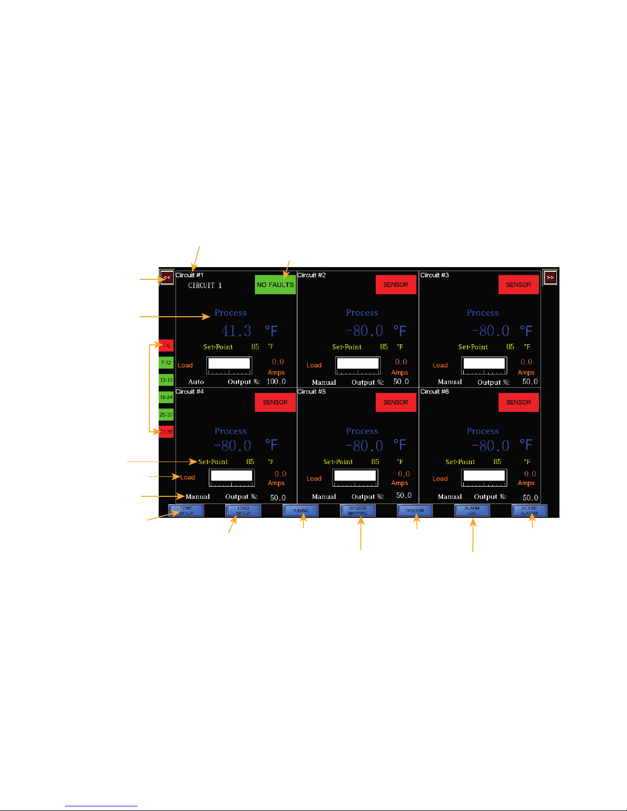
Main Menu Screen
Circuit Number and Circuit Identification
(1-6, 7-12 for 5 Cir
Sensor Mapping Menu
Active Alarms Menu
Alarm Log Menu
The ITAS/ITLS Touch Screen Computer is extremely user friendly and quite intuitive. Navigation to any other
screens or any 2 or 6 circuit grouping of circuts is accomplished by selecting the blue labeled buttons along the
bottom of the screen or in the upper right or left hand corners.
The main menu screen displays alarm status, circuit number, circuit name, process and set point temperatures,
current load demand, manual/auto control state and output percentage for 2-6 circuits at a time. See Figure 1.
Figure 1
Alarm Status & Type
2-6 Circuit
Navigation
Buttoon (x2)
Process
Temperature
Alarm Status by
2-6 Circuit Grouping
and up Systems
or 1-2, 3-4 for 2-4
Circuit Systems
up to 72 Circuits)
cuit
Temperature
Setpoint
Current Load
Control State
& Output %
Quick Launch to
Temperature Menu
Quick Launch to
Load Setup Menu
Quick Launch to
Tuning Menu
Quick Launch to
Quick Launch to
SystemMenu
Quick Launch to
Quick Launch to
8
Page 13
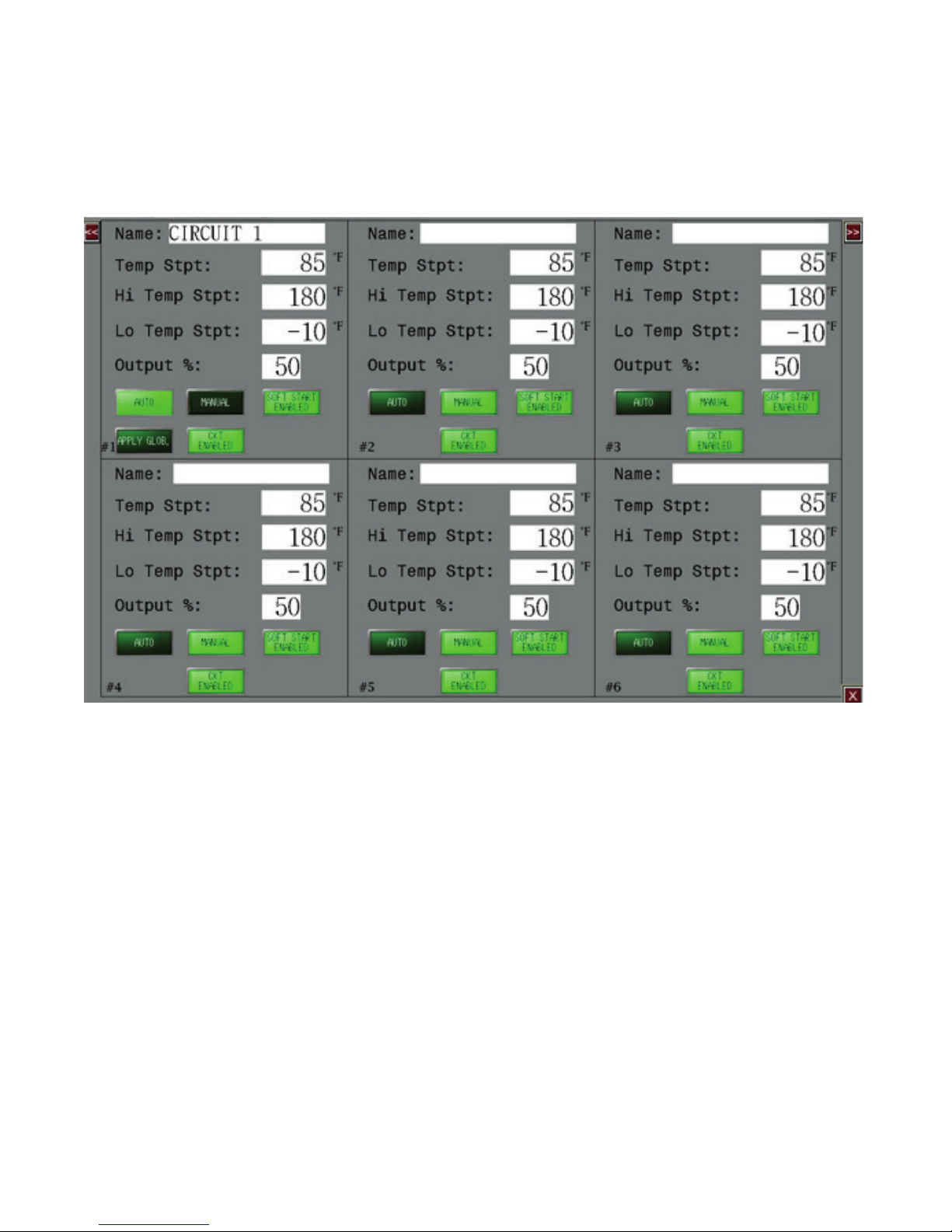
Temp Setup Menu
The Temp Setup button at the bottom of the screen is a quick launch to the Temperature Property Sheet which is
simply a series of tabaulated screens. See Figure 2.
Figure 2
Each block contains input cells for the panel operation. For example, temperature and overide controls are located
within the Temp Setup Screen.
Navigation notes:
1. Each screen illustrates 2 or 6 circuits at a time. To make setting changes to circuits beyond the current screen
within the menus, one must select the Circuit Navigation buttons in the upper right or left of screen.
2. For most screens, to save your settings and exit back to the mail screen, select the “X” button in the lower right
corner of the screen.
9
Page 14
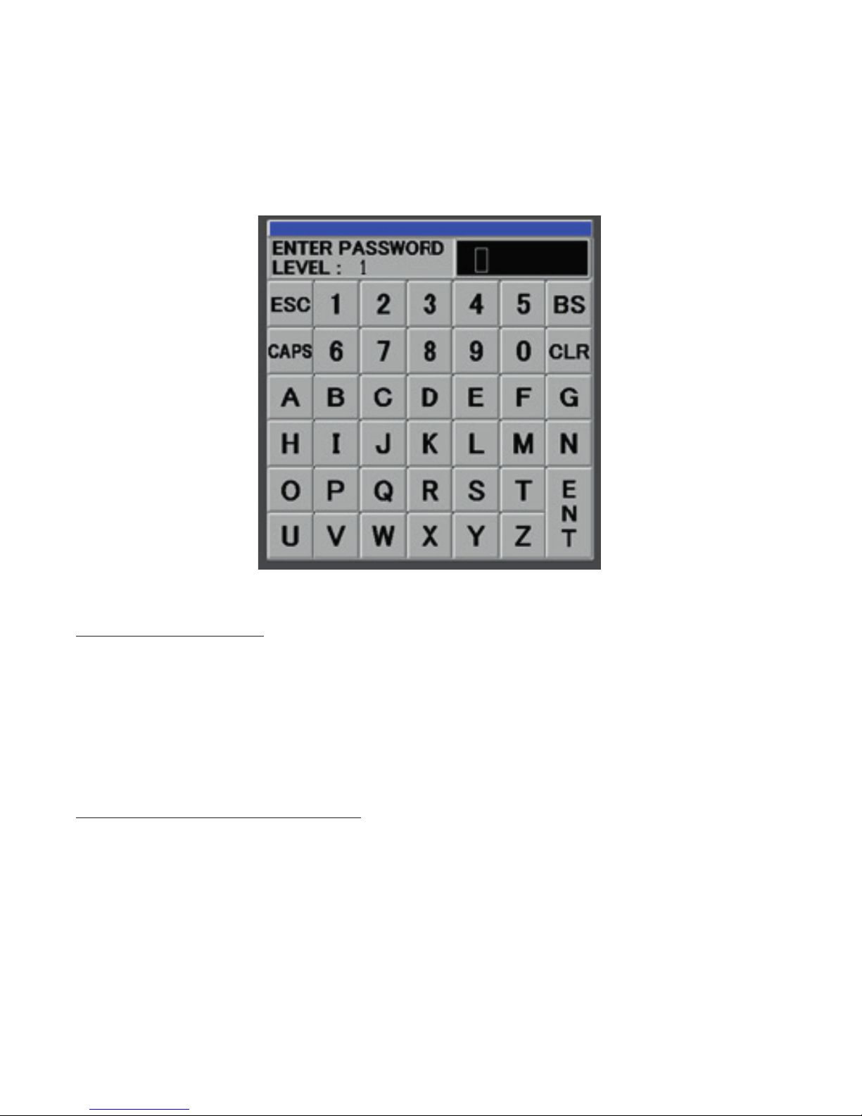
Security Levels & Password Screen
After touching the Temp Setup button, but before the Temp Setup Menu is presented, a pop-up screen requesting a password will appear. See Figure 3:
Figure 3
Initial factory set passwords for the below levels of Security are:
Level Title Code
4. Manager 999
3. Engineering 55
2. Supervisor 20
1. Operator 100
Enter the appropriate password and then hit ENT to continue to the setup screen.
Each of the above Security Levels has predefined accessibility and rights within the programming of the control
panel. They include:
Level Title Accessibility/Rights
4. Manager All customer pages, all passwords and Setpoints editing
3. Engineering All customer pages, Engineering password and All Setpoints editing
2. Supervisor Setpoints, Tuning and Sensor Mapping Tabs & All Setpoints editing
1. Operator Setpoints Tab. Temperature Set Point editing
Changes to specific areas within the menus can only be made once the correct security level code has been
selected.
10
Page 15
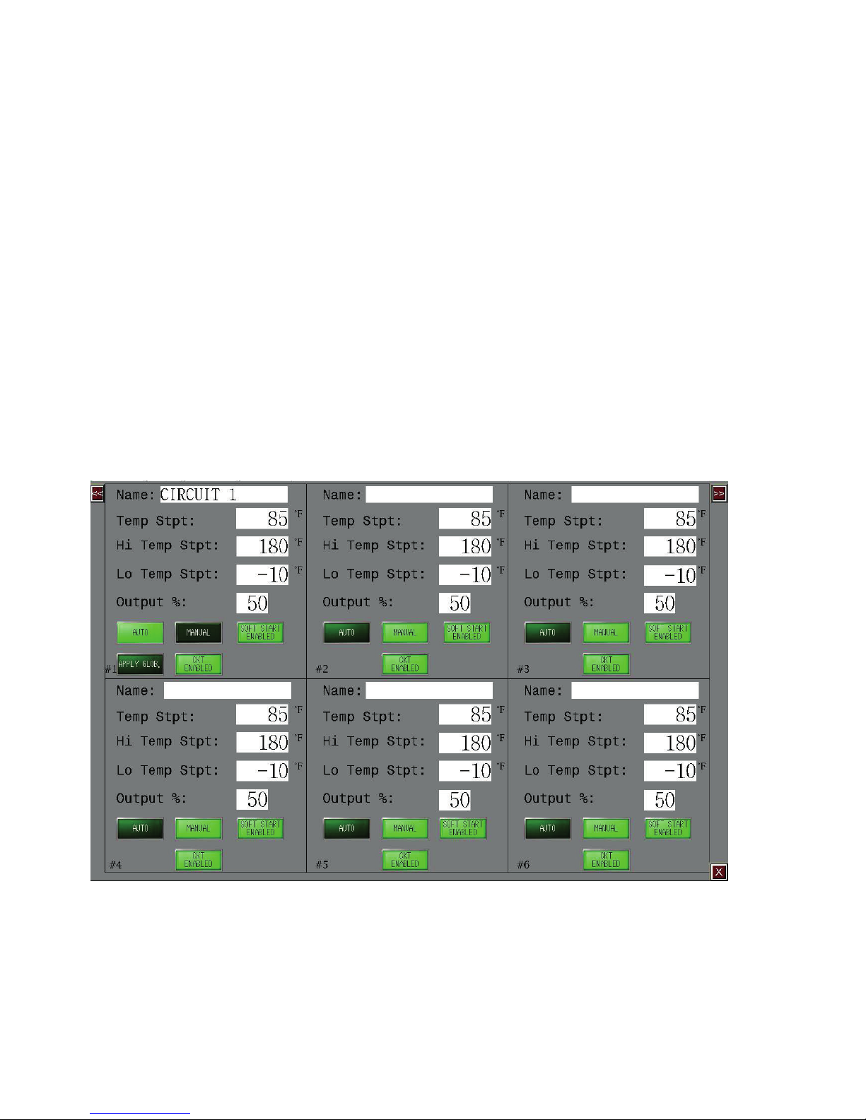
Temp Setup Menu
The Temp Setup Menu tab (See Figure 4) contains input cells for the following settings for each circuit:
• Customized Naming of each Circuit
• Process Temperature Set Point
• High & Low Temperature Alarm Limits
• Maximum allowable GFEP (Ground Fault Equipment Protection) Alarm Limit
• Output behavior, whether Automatically or Manually
• Manual Output Load Percentage (if enabled)
• Circuit Output Override (Enable or Disable Each Circuit)
Additionally, there exists a “Global Setting” within the Circuit# 1 Grid
• Apply Globally Setting
Figure 4
11
Page 16
Temp Setup Menu Navigation notes:
Apply T
1. Each screen illustrates 2 or 6 circuits at a time. To make setting changes to circuits beyond the current screen
within the Temp Setup Menu, one must select the Circuit Navigation buttons in the upper right or left of screen.
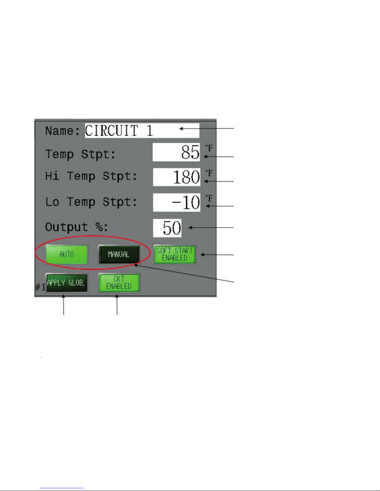
Figure 5 illustrates the input cell identification and location for a single circuit within the Temp Setup Menu:
Figure 5
Circuit Name
Temperature Setpoint
High Temperature
Alarm Limit
Low Temperature
Alarm Limit
emperature
Settings to all
Circuits
Manual Output
Load Percentage
Soft Start
Enable/Disable
Auto/Manual
Output Operation
Enable/Disable
Circuit
12
Page 17

Definitions for each of the Temp Setup Input Cells:
Name: Customize the Name of this individual circuit or loop
Temp STPT: Process Temperature Set Point (degrees F or C)
HI STPT: High Temperature Alarm Limit (degrees F or C)
LO STPT: Low Temperature Alarm Limit (degrees F or C)
Auto/Manual: Select Auto if you wish the Output behavior to be a function of a PID Algorithm or ON/OFF
Control (See Tuning Tab for selection)
Select Manual if you wish the Output to be driven by a pre-determined Output Percentage.
Enter the desired % output.
Disable Output: Select this check box if you wish to turn off or disable this circuit.
Apply Globally: This allows the user to copy all of the settings or Circuit Parameters from Circuit #1 to all other
available circuits.
Apply Settings Globally
The ITLS/ITAS has a feature which allows the user to apply settings from a single circuit to all of the remaining
circuit within the system. Within Circuit #1 on the Load Setup Menu (See Figure 6), complete the input of the parameters and select the “Apply Glob” button to mirror these settings across all circuits.
Soft Start Feature
These control panels are ideal for controlling heat trace
cable. Certain heating cables exhibit inherent current
inrush in colder temperatures. This inrush can cause
nuisance breaker tripping. To limit inrush current on
the overall system, a proprietary soft start algorithm is
applied during system start-up. This will ONLY occur
while the operation mode is set to AUTO.
The soft start program will increment output % by
1% every 1 second until the desired temperature is
reached or the output % achieves 100%. After the soft
start program completes its cycle, the control mode of
the system will either be PID or ON/OFF Control Mode,
depending what was selected by the user.
The soft start program will not function if the control
mode is set to Manual.
The default setting of the proprietary soft start feature
for each circuit is “enabled”. However, the soft start
feature may be disabled if so desired by the owner. The
owner has the option to manage the soft start feature
on each circuit individually.
See Figure 5.
13
Page 18
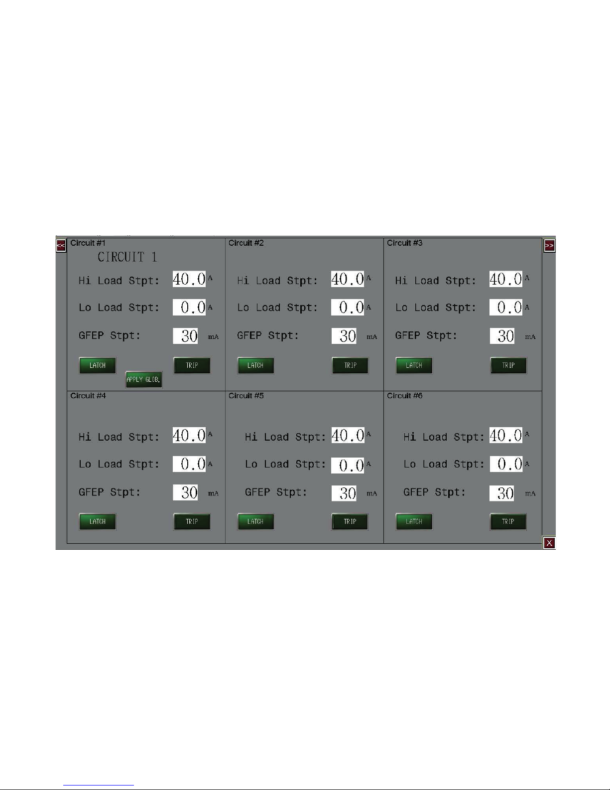
Load Setup Menu
The Load Setup Menu (See Figure 6) contains input
cells for the following settings for each circuit:
• High & Low Load Alarm Limits
• Trip and/or Latch Enabled/Disabled (Output Permis-
sion) upon GFEP Violation
• Maximum allowable GFEP (Ground Fault Equipment
Protection) Alarm Limit
Figure 6
Additionally, there exists a “Global Setting” within the
circuit# 1 Grid
• Apply Glob. Setting
14
Page 19

Definitions for each of the Load Setup Menu Input Cells
Load HI Stpt ................. High Current Alarm Limit (Amps)
LoadLO Stpt ................. Low Current Alarm Limit (Amps)
GFEP: ........................... Maximum Allowable Leakage Current setpoint (milliamps)
Trip (GFEP): .................. Enabled: If the GFEP limit is met, the output will be 0%.
Disabled: If the GFEP limit is met, the output is unaffected.
Latch (GFEP): ............... Enabled: If the GFEP limit is met, the alarm condition will remain until it is manually cleared.
Disabled: If the GFEP limit is met, the alarm condition will be cleared once the GFEP vari-
able is less than the GFEP setpoint
Apply Globally: ............. This allows the user to copy all of the settings or Circuit Parameters from Circuit #1 to all
other available Circuits.
Apply Settings Globally
The ITLS/ITAS has a feature which allows the user to apply settings from a single loop to all of the remaining loops
within the system. Within Loop #1 on the Setpoints Tab (See Figure 4), complete the input of the parameters and
select the “Apply Globally” button to mirror these settings across all loops.
15
Page 20
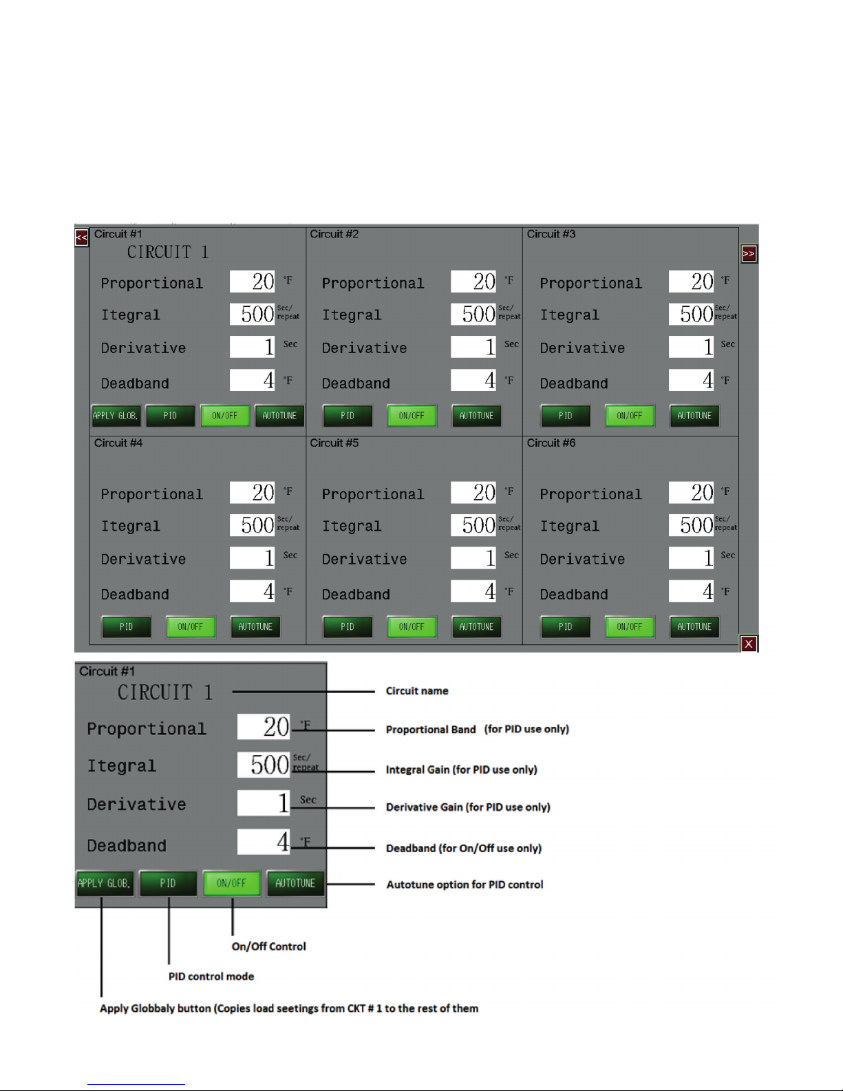
Tuning Menu
The owner has a choice of how the output is to be operated: Auto, Manual or Off. These selections are made within
the Temp Setup Menu. If “Auto”, or Automatic Control Operation is desired, then the tuning of the automatic control is accomplished via the Tuning Menu.
Figure 7
16
Page 21

Control Modes: ON/OFF, PID & Autotune
ON/OFF
• Select ON/OFF if you wish the operation of the heat-
ers to be 100% ON when a demand for heat exists
and 0% once the Set Point Temperature of the Process is achieved.
• The Deadband is enabled while in ON/OFF control
mode.
• The Deadband is the temperature range equally
divided above & below the temperature set point,
where the controller will not take corrective action.
o Example: A setting of “10” for the deadband will
result in a deadband that is 5 degrees above and
below the temperature setpoint.
• The deadband is adjustable in 2 degree increments.
It’s default is 10.
PID
• Select PID if you desire PID Control of the load.
• The Proportional Band (P), the Integral (I) & Deriva-
tive (D) are modes of control that work in union to
bring the process variable to setpoint as smoothly
and quickly as possible. They are enabled while in
PID Control mode.
• The P, I & D will be automatically established during
the Autotune procedure (see above).
• Additionally, the P, I & D may all be manually estab-
lished by the user. Great care should be taken when
manually establishing the P, I & D.
• Proportional Band: The temperature band expressed
in degrees within which the controller‘s proportioning action takes place. (Note: The wider the proportional band, the greater the area around the setpoint
in which the proportional action takes place.) This is
sometimes referred to as gain, which is the reciprocal of proportional band.
Autotune
• If the Autotune Feature is selected, then the PID parameters will be calculated and entered by the system once the Autotune function has completed its
demand profile function.
• The Autotune function establishes the individual P, I
& D (Proportional Band, Integral & Derivative) control
modes. These modes help to bring the process variable to the setpoint temperature as quickly as possible.
• In order to properly calculate the P, I & D modes,
the Autotune program requires a 25 degree rise in
sensed temperature after initiating the program. If
within 30 minutes the temperature will not reach its
setpoint, the Autotune algorithm will be canceled
and old PID values will be used.
• Once the Autotune feature is activated, you must not
change the menu page until the Autotune algorithm
is completed. Changing the page will cause the Autotune algorithm to shut down.
• The Autotune function is a one-time algorithm set up
of the P, I & D control modes. Should your process
variables change significantly, it is suggested to that
the Autotune feature be turned off and then reinitiated.
Tuning Tab Navigation Notes:
1. Each screen illustrates 6 loops at a time. To make
setting changes to loops beyond the current screen
within the Tuning tab, one must select the Loop Navigation buttons in the upper right or left of screen.
17
Page 22
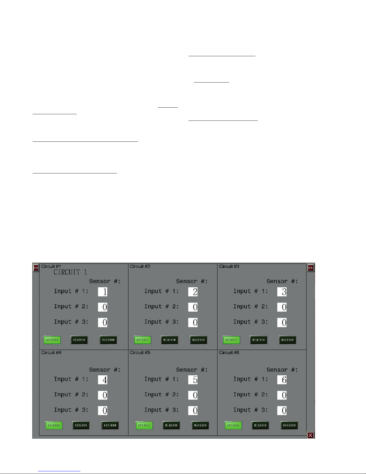
Sensor Mapping
The ITLS and ITLSC1D2 models provide the owner
with customizable sensor mapping. This becomes a
very powerful and desirable feature when the owner
needs added flexibility in controlling the circuit outputs
beyond the standard single sensor input.
1. Sensor Mapping is the assignment of one or more
Sensor Inputs to one or more output circuits.
Sensor (Input) Mapping is accessed via the Sensor
Mapping Menu.
Sensor Mapping
Ambient or Line Sensing, Single Sensor
A single sensor (RTD) may be mapped (or linked) to
multiple output circuits. This allows several circuits to
be controlled by a single sensor.
Minimum, Maximum, Averaging
Several sensors may be mapped to a single output circuit. This allows a single circuit to be controlled by the
minimum, or the maximum or the average temperature
of all of the sensors mapped to that output circuit. This
may be desirable on long runs or zones which realize
varying temperatures or weather conditions at different
times of the day.
Multiple Sensor Mapping
A single sensor may be used independently or combined with other sensors to control more than one circuit.
For Example:
The average temperature of Sensors 1, 3 and 5
is used to control Circuit 1 while simultaneously
the maximum Temperature of Sensor 3, 4 and 5 is
used to control Circuit 2.
Combining Sensing Types
The owner may need to have multiple line and/or ambient sensing control scenarios occurring simultaneously.
For example, these may be occurring simultaneously:
1. Circuits 1, 2, 3, 4, and 5 are all controlled by a single
RTD (Sensor 1) that is sensing the ambient temperature (Ambient Sensing)
2. Circuit 6 is controlled by Sensor Input 2 which is
strapped to a process pipe. (Line Sensing)
Sensor mapping is accomplished within the Sensor
Mapping Menu. See Figure 8.
This does not apply when only 1 Input/Circuit selection
is made from the Order Table.
Figure 8
18
Page 23
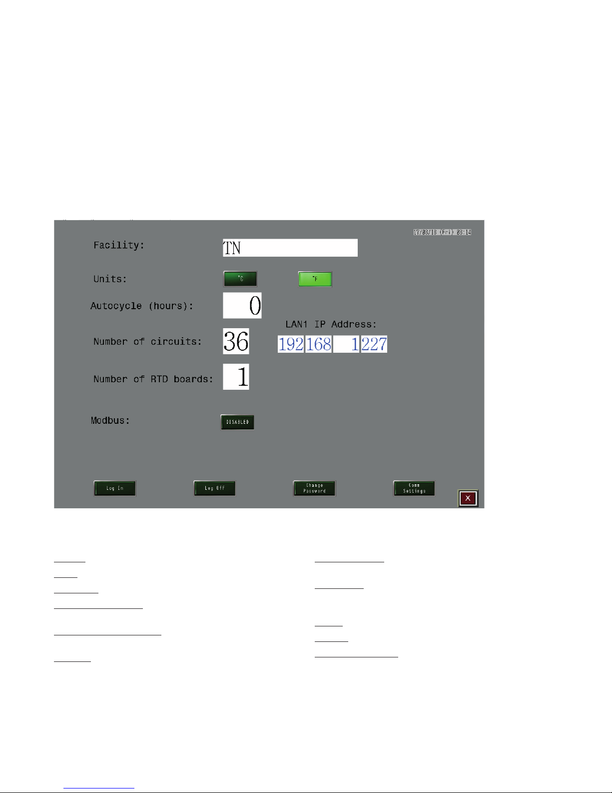
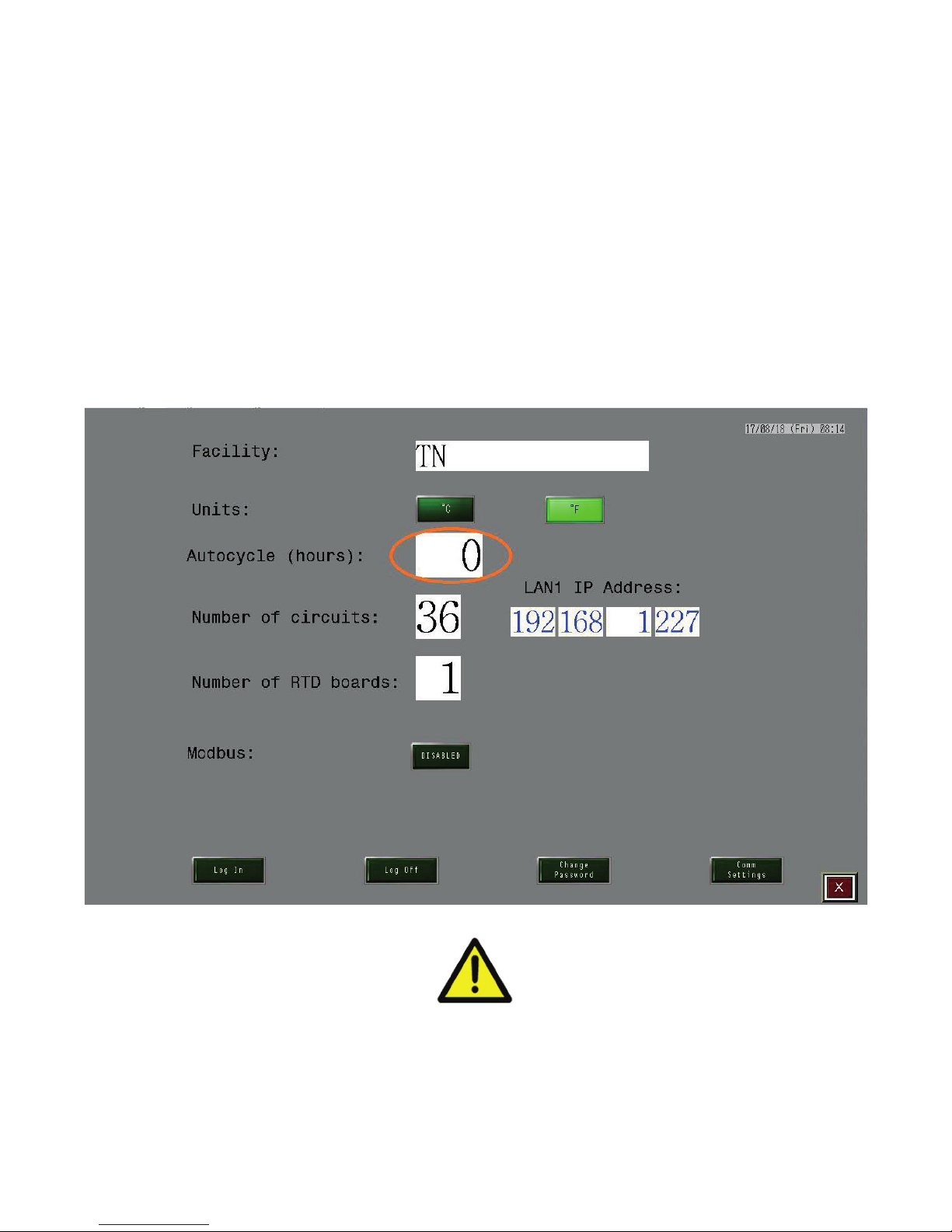
System Properties
Several informative items and general settings are
available within the System Menu.
The System tab is only available to the two highest
owner security levels: Manager and Engineer.
The Autocycle function is reviewed in the Autocycle
Feature section.
Figure 9
Here, one can enter/revise the Facility Name, Date,
Time, Temperature Units, Auto Cycle Interval and Security Codes. The Manager has access to all security
codes while the Engineer has access to only the Engineering Security Code. See Figure 9.
The Security Passwords and the respective rights for
each security level are reviewed in the Security Level
and Password Screen Section.
System Page Definitions
Facility – name of the facility
Units – degree Celsius or Fahrenheit
Autocycle – Autocycle feature. Value of 0 disables it
Number of circuits – number of SSR circuits (not
boards) installed in the panel
Number of RTD boards – Number of RTD boards installed in the panel
Modbus – Modbus feature can be disabled or enabled
to speed up processing and screen update current security level password
Comm Settings – used to select correct Modbus communication parameters (baud rate, parity, stop bits, etc)
IP Address – present IP address of the HMI screen. IP
address can be changed by pushing Comm Settings
button.
Log In – used to change current security level
Log Off – used to log off from the system
Change Password – used to change current security
level password
19
Page 24
Auto Cycle Feature
During prolonged down time periods, typically during
the summer months, it advisable to intermittently exercise the loops. This exercising of the loops is accomplished via the Autocycle feature.
To enable the Auto Cycle feature, select an Auto Cycle
Interval greater than 0 hours within the System tab.
See Figure 9. The Auto Cycle feature is disabled when
the Auto Cycle Interval equals 0 hours.
Figure 10
On a sequential circuit basis, the Autocycle feature periodically monitors system performance between 1-999
hours. The minimum and maximum values for Current
Load, GFEP and Temperatures are stored. Once the
new high or low value is attained the old value is overwritten and displayed in the Autocycle tab text boxes.
See Figure 10.
This provides a certain level of preventative maintenance of the system as Faults (Alarms) will present
themselves accordingly. Problem areas can be addressed during non-essential operating periods.
It is NOT advisable to engage the Auto Cycle
feature during normal operating periods. The
heating cables will become fully energized for
approximately 2 minutes throughout the Auto
Cycle Interval which could cause undesirable
temperature overshoot.
WARNING:
20
Page 25
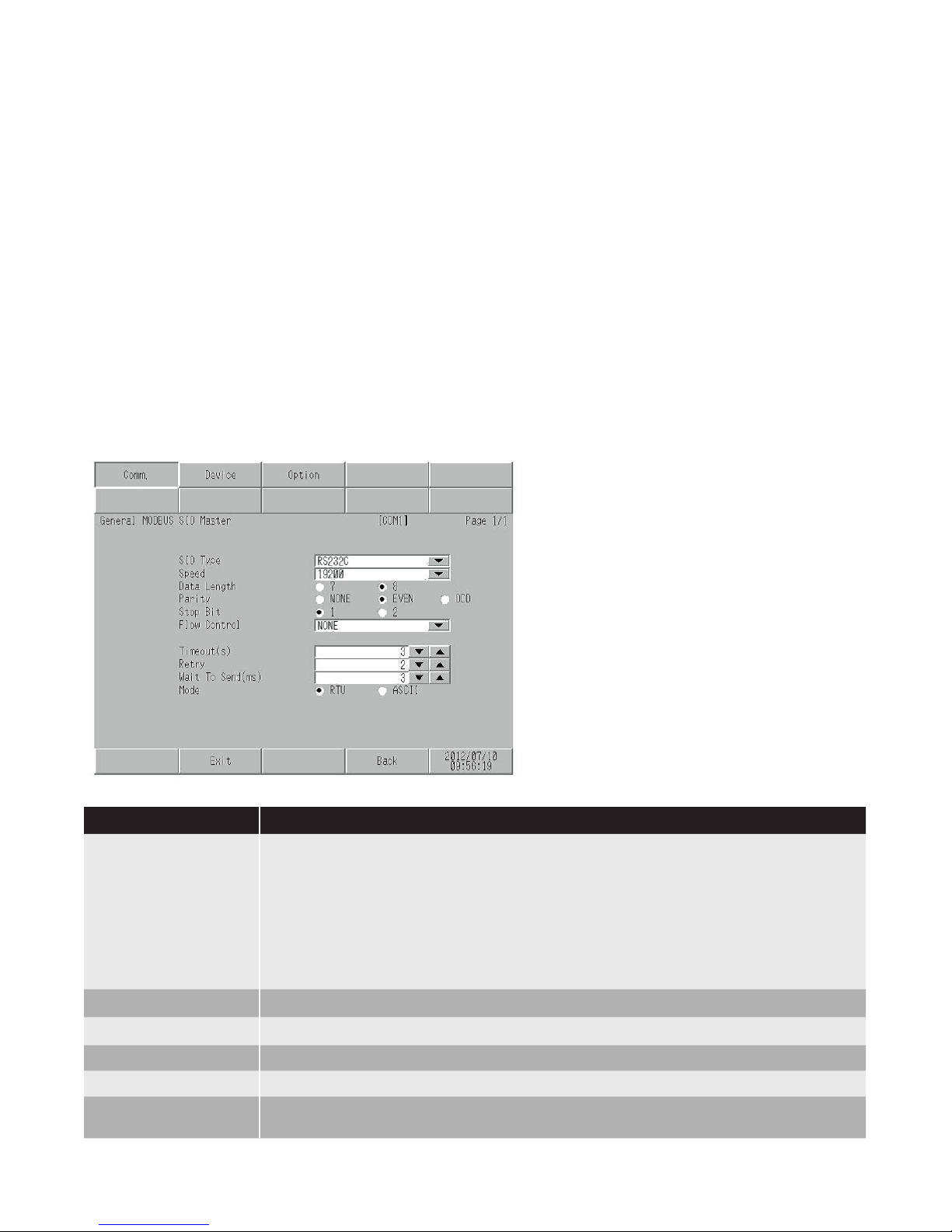
Communications
All changes to the MODBUS settings are achieved via
the COMMS screen. See Figure 11.
The Comms (Communications) screen may be accessed by selecting the COMMS button located at the
bottom of the System screen. The MODBUS Address,
Communication Speed, Parity and Stop parameters
are set within the Communications screen.
For complete communications specification details on
ModBus messaging, Registers and Sensor Mapping,
please reference our “ModBus Wiring and Registry
Map Instructions Document A-60682-04. This is an addendum to the PK497 manual. Go to the ITLS or ITAS
product pages and search in the Technical Resources
Tab at: www.chromalox.com.
Figure 11
Remote Monitoring
& System Management
Users may monitor as well as adjust the System Parameters settings of the panel remotely. The files required for this feature are available to the owner. Due to
the frequent program updates, we ask that you contact
the factory for the most recent release version.
Communication Settings
To display the setting screen, touch (Device/
PLC Settings) from (Peripheral Equipment Settings) in offline mode.
Touch the External Device you want to set from
the displayed list.
Setup Items Setup Description
SIO Type Select the SIO type for communicating with the External Device.
IMPORTANT
In the communications settings, set (SIO Type) correctly according to interface specifications of the Display.
If you select an SIO type that the serial interface does not support, proper operation
cannot be guaranteed.
Refer to your Display Manual for details on the serial interface specifications.
Speed Select the communications speed between the External Drive and the Display
Data Length Select a data length
Parity Select how to check parity.
Stop Bit Select a stop bit length.
Flow Control Select the communications control methond to prevent overflow of transmission and
reception data
21
Page 26

Alarm Log
The purpose of Alarm Log is to record every alarm
condition with a date and time stamp. This log may be
viewed via the ALARM LOG button at the bottom of the
main screen. See Figure 12.
Alarm condition example: Sensor Error alarm on circuit
18 will be recorded as “11/08/12 – 13:38:48 SENSOR
ALRAM CKT 18”. Every alarm event is saved into a text
file (\Storage Card\log5.txt). Each event is appended to
the file string on a new line.
This table holds up to 750 events (alarms). If the number of entries exceeds 750 then the event that is last
Figure 12
on the list (by date) will be removed from the table. This
process repeats indefinitely. Once an alarm has been
recovered, it can be removed from the list by pushing
the clear recovered alarm button.
To extract these files, one must:
1. Plug a USB flash drive into the USB port located on
the back of the ITLS/ITAS computer. Go to Alarm
Log Screen and push green button on the right of
the screen labeled “Write Alarms to USB.”
Move Upward – moves cursor one position up
Move Downward – moves cursor one position down
Clear All Recovered Alarms – clears all recovered
alarms from the alarm log
Clear Recovered Alarm – clears selected recovered
alarm from the log
Acknowledge All – acknowledge all present alarms
Acknowledged – acknowledge selected alarm
Roll Up – move cursor one position up
Roll Down – move cursor one position down
Write Alarms to USB – saves alarm log into USB thumb
drive
View USB – reads previously recorded alarm log from
the USB thumb drive
22
Page 27
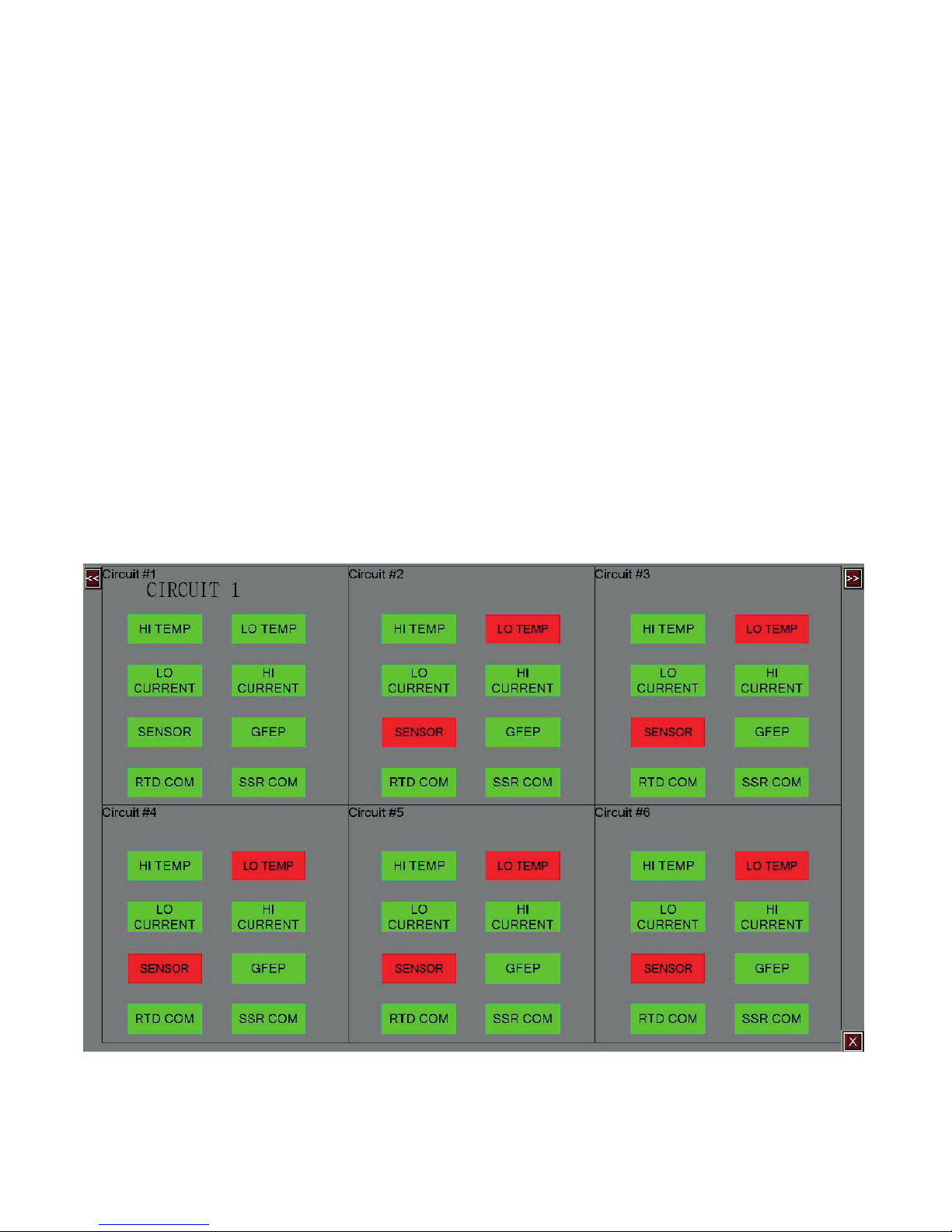
Active Alarms
Alarms within any 6-circuit or 2-circuit grouping are indicted by RED squares in the left and right panels on
any screen. If the square is GREEN, then no faults exist
within that 6-circuit grouping. Once a fault is realized
within any 6-circuit grouping, one may view the individual alarm circuit or circuits in two different ways:
1. When in the Main Display screen, one may navigate
to the desired 6-circuit grouping via the Navigation
buttons found in the upper right hand or upper left
hand corner. Alarm conditions are illustrated within
each circuit window. Up to three alarm conditions
can be illustrated for any single circuit on the Main
Menu screen.
2.
One may view the status of all fault conditions by selecting the ACTIVE ALARMS MENU button located
at the bottom of the main display screen. To navigate
to the desired 6-circuit grouping, one must press the
Circuit Navigation but-tons found in the upper right
or left corner of any screen. See Figure 13.
Figure 13
Clearing Alarms
Except for a Communications Alarm and a Latched
GFEP Alarm, all other alarms are cleared once the acceptable parameters are achieved.
23
Page 28

Alarm Troubleshooting
The Alarm Condition, the resultant Output and the Design Behavior for each Alarm type can be found in Table 2
below.
Table 2
Alarm Type Condition Output Design Behavior
HIGH TEMP
LOWTEMP
GFEP
HI CURRENT
(LOAD on Faults
Screen)
LO CURRENT
(LOAD on Faults
Screen)
SENSOR
COMM
Sensed Temp
=> Hi Temp
Setpoint
Sensed Temp
<= Lo Temp
Setpoint
Sensed GFEP
Current =>
GFEP Setpoint
Sensed Load
Current =>
Hi Current
Setpoint
Sensed Load
Current <= Lo
Current
Setpoint
Sensor Open,
Sensor Shorted,
Sensor Fault
Communication
Error
No change Alarm will be cleared automatically when
Sensed Temp < Hi Temp Setpoint
No change Alarm will be cleared automatically when
Sensed Temp > Lo Temp Setpoint
Trip Latch
No No
Yes No
No Ye s
Yes Ye s
Output will switch to Manual
Mode
No change Alarm will clear automatically when
Output will switch to Manual
Mode
Output will switch to Manual
Mode
Output will remain at selected
output %.
Output will go to
0% (OFF) while in
alarm state
Output will remain at selected
output %.
Output will go to
0% (OFF) until
alarm is reset
Alarm will be cleared automatically when
sensed GFEP Current < GFEP Setpoint
The Alarm condition may only be cleared
with a manual RESET of the GFEP Alarm.
Alarm will be cleared automatically when
sensed Load Current < Hi Current Setpoint
Sensed Load Current > Lo Current Setpoint. If your output is turned OFF, GFEP
and Load values will not be updated.
Alarm will clear automatically when the
RTD resistance is between 75.44W -
311.56W. Check if your sensor wire is not
damaged and that it is properly connected
to the Sensor board.
Make sure that the communication cable
that connects the Touchscreen computer
with boards inside enclosure is properly
connected and/or not broken.
Press “RESET ALM” to reset this alarm.
24
Page 29
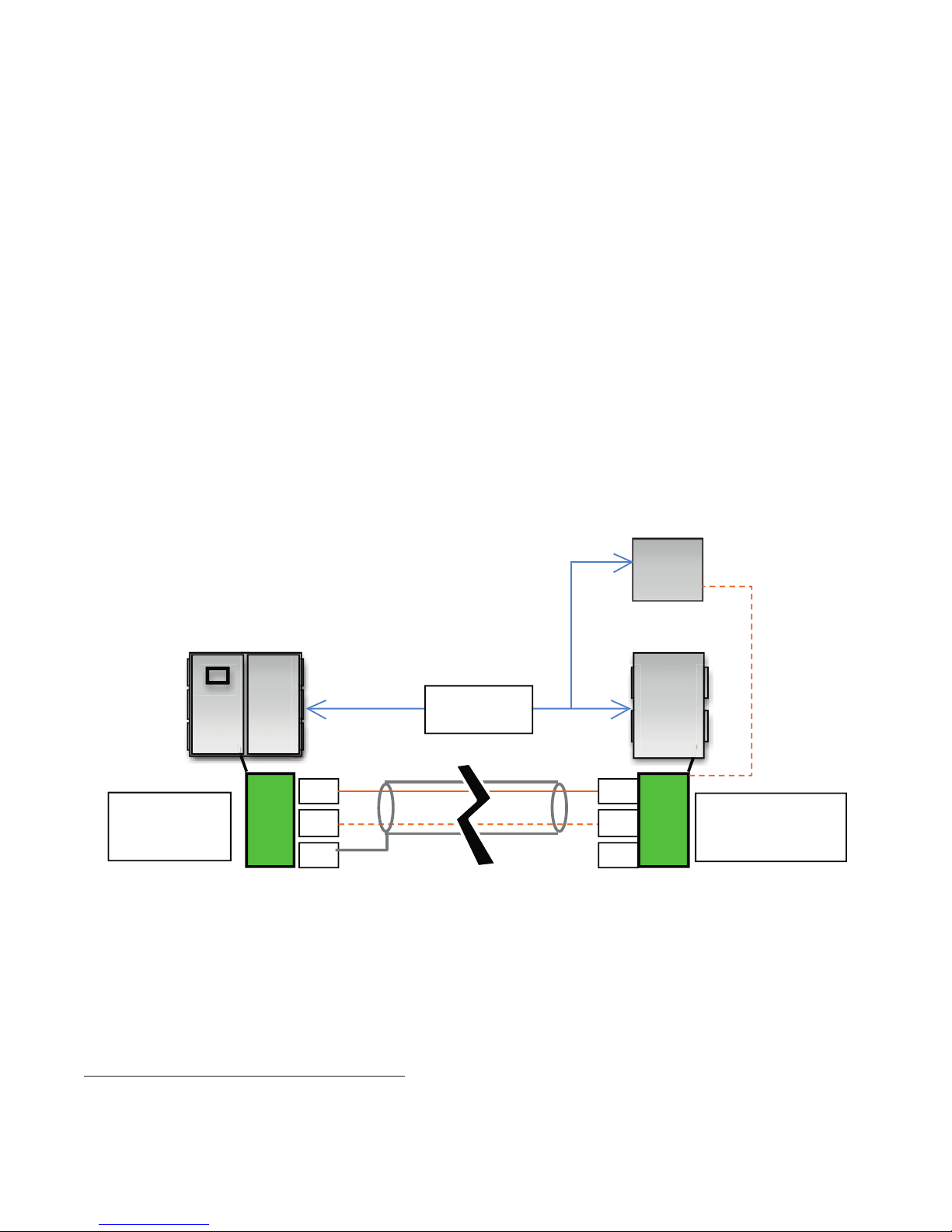
Extension Panels
D
Connecting an Extension panel or a
Remote Sensor Panel to the Main Panel
Below is the procedure to connect an Extension or
a Remote Sensor Panel to the Main Panel. The Main
Panel will manage the circuits in the Extension Panel
and the inputs of the Remote Sensor Panel.
Procedure:
1. Turn off the power to the system.
2. In the main panel (the one with a touch screen computer) locate the distribution board (0113-10246)
and verify that jumpers J.16 and J.17 are set in positions 1 & 2.
3. Connect one end of the twisted pair cable into connectors J15.1 (RX+) and J15.2 (RX-) on the distribution board of the Main Panel. Connect the other end
of the twisted pair cable into connector J15.1 RX+
and J15.2 (RX-) on the distribution board of the Extension panel.
Figure 14
Make sure that RX+ is connected to RX+ and RX- to
RX-. (See Diagram Below)
4. Connect the metallic shielding material (see wire
specification below) to the ground of the base panel
Distribution Module. However, DO NOT connect
the metallic shielding to the Extension Panel Distribution Module. (See Diagram Below)
5. If the number of loops needs to be changed, power
up the system and login into the setup menu using
5731 as the password. Go to the “System” tab and
select the desired number of loops and press “OK”.
6. Cycle power to the system.
**Note - a 2 or 4 Circuit Extension Panel may be
added to a 6-48 Circuit system but not vice versa.
Remote Sensor Panel
Main Panel
2,500 FT
(775 M) Max
RX+
Main Panel
Distribution
Module
RX-
GN
Extension Panel or Remote Sensor Panel
Considerations
Environmental influences such as EMI/RFI can compromise the communication signal between the Extension
or Remote Sensor Panel and the Main Pane. The use of
properly designed cable will protect against and minimize
these influences.
Here is a design guide for extension panel wiring:
RS-485 Max. total cable length ........... 2,500 ft (800 M)
RS-485 Wire specification .........T1/E1/DSL compatible
24-AWG shielded cable
Extension Panel
RX+
-
RX
GND
Chromalox uses the following vendor and cable item
as a viable reference:
Example Vendor: ................................................L-com
Typical Specification: ...2 - 120 Ohm (E1) Shielded Pair
Vendor Item Number: .................................... TSC9928
Available at: .............................. http://www.l-com.com
Extension or Remote
Sensor Panel
Distribution Module
25
Page 30
Wireless Temperature Sensing
No Maintenance Needed.
Overview
Chromalox now provides fully integrated Wireless Temperature Sensing Solutions for Heat Trace applications
in ordinary and hazardous locations.
The components of the Chromalox Heat Trace Wireless
Temperature Sensing system include the IntelliTrace
ITLS or ITAS Series Heat Trace Control Panel and specific industrial wireless transmitters which are paired
with appropriate temperature sensors.
Control Panel
When the wireless temperature sensing feature is selected, the IntelliTrace Control Panel is properly configured at the factory and internally equipped with
an industrial-duty WirelessHART® certified wireless
gateway, antenna and the necessary communication
accessories.
The panel facilitates both wired and wireless temperature sensor inputs and the touchscreen computer HMI
distinguishes wireless circuits from wired ones. Several of the IntelliTrace HMI screens are impacted when
Wireless Temperature Sensing is ordered and enabled
at the factory: The Main Screen and Sensor Mapping
Menu.
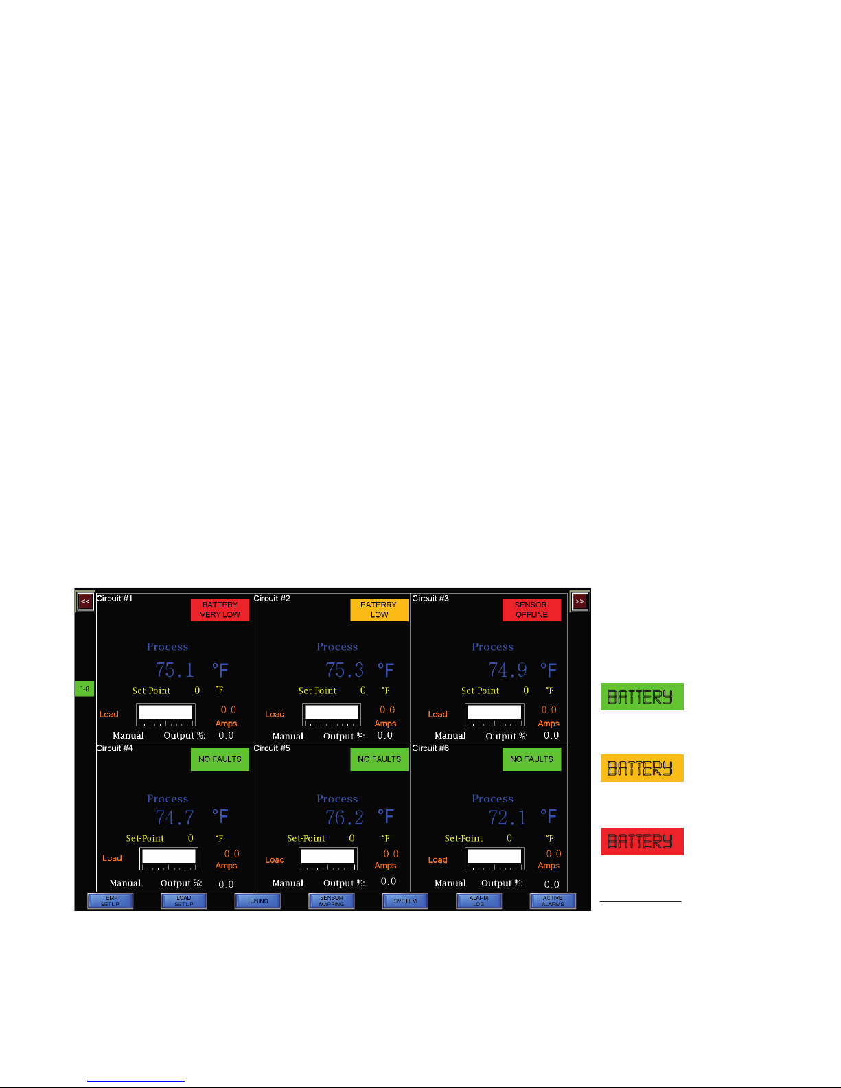
Main Menu
On the main menu screen, the alarm status will appear
as BATTERY when the transmitter battery of a wireless circuit is due to be changed. Each wireless circuit
has its own transmitter battery life meter. This provides
three levels of remaining battery life so that you may
properly plan service before it is needed.
Wirless Transmitter
Battery Meter
BATTERY
Battery Life Good.
BATTERY
Battery Life Low.
Plan for Maintenance.
BATTERY
Battery Life Very Low.
Perform Maintenance
Immediately.
26
Page 31

Sensor Mapping Tab
Wireless sensors will automatically show up in the SENSOR window of the I/O Mapping Tab. They are labeled as
WS #1, WS #2, etc., and can be assigned to any output circuit.
Faults Page
The BATTERY fault state on the Faults page will change from Green to either Orange or Red depending on the
remaining battery life of the Wireless Transmitter.
Wireless Transmitter
Chromalox has chosen the Rosemount® 248 Wireless Temperature Transmitter. This transmitter is WirelessHART®
certified and it may be pipe or structure mounted. When deployed in a Mesh network, this transmitter is actually
both a transmitter and a receiver (also known as a Bi-Directional Wireless Device).
The 248 Transmitter is offered in either aluminum or polymer housing and is available with or without a matching
universal mounting bracket. A battery is also required and ordered as a separate item. Manufacturer’s data sheets
and user manuals are available in the technical resources tab within the Heat Trace products / Wireless Temperature Sensing section at www.chromalox.com
27
Page 32

Rosemount 248 Wireless Temperature
Transmitter Features
• Output - WirelessHART 2.4 GHz
• IEC 62591 Compliant
• Update Rate – 1 sec to 60 min - user selectable
• Accuracy +/- 0.45oC @ 20oC
• Wireless radio
o 2.4 – 2.485 GHz
o 15 channels
o IEEE 802.15.4 compliant
• Power Module
o Lithium Thionyl Chloride with PTB enclosure
o 7 to 10 year life (1 minute update rate)
• Housing
o IP66/67
o NEMA 4X
• Self-Calibrating Unit
• Direct Pipe or Flat Surface Mounting
• Accepts RTD & Thermocouple Sensors & mV input
• The following approvals/certifications:
Polymer Housing
F
Aluminum Housing
Please see the Rosemount 248 Data Sheet and Instruction Manual for completed details. Manufacturer’s data
sheets and user manuals are available in the technical resources tab within the Heat Trace products / Wireless
Temperature Sensing section at www.chromalox.com
Ordering Information:
There are many design and feature options available on
the Rosemount 248 model. Chromalox has standardized on the following:
Wireless Temperature Transmitter
Rosemount 248 Wireless Temperature Transmitter,
USA Intrinsically Safe and Non-incendive, Aluminum or
Polymer Housing, with 1/2-14 NPT Conduit Entry Size,
WirelessHART, 2.4 GHz, External Omni-directional Antenna (Aluminum Housing only), 5-point Calibration,
External ground lug, 60Hz & 3 Year Warranty
Desription (Manufacturer Model No.)
Aluminum Housing with universal mounting bracket
(248DXI5D2NSWA3WK1B5C4Q4G1WR3)
Aluminum Housing without universal mounting bracket
(248DXI5D2NSWA3WK1C4Q4G1WR3)
Part Number
0108-70477
0108-70478
Polymer Housing with universal mounting bracket
(248DXI5P2NSWA3WP5B5C4Q4WR3)
Polymer Housing without universal mounting bracket
(248DXI5P2NSWA3WP5C4Q4WR3)
Battery for 248 Wireless Trans0mitter with Aluminum Housing Only 0108-70432
Battery for 248 Wireless Transmitter with Polymer Housing Only 0108-70481
0108-70479
0108-70480
28
Page 33

Universal Mounting Bracket
The Rosemount 248 Wireless Temperature Transmitter may be ordered with or without a matching Universal
Mounting Bracket (see above table). This bracket eases and enables transmitter mounting to either pipe structures or flat structural surfaces.
Rosemount 248 Wireless Temperature Transmitter with Universal Mounting Bracket
(Shown With Aluminum Housing Model)
Pipe Mounting
Structure Mount
29
Page 34

Transmitter Power Module (Battery)
Aluminum
The transmitter power module must be installed prior to device configuration and device use. It may be removed
from the device in between configuration and commissioning.
The Polymer housing transmitter utilizes the Green Power Module while the Aluminum housing transmitter uses
the Black Power Module. These are dramatically different in physical dimensions and may not be used universally.
Exploded view of the two models:
Housing
Transmitter
Base
Power
Module
Temperature Sensor
Although other RTD sensors may be utilized, Chromalox has standardized on the RBF185M type Heat Trace
Sensor. This industrial duty RTD is designed to be Pipe
Mounted and it comes complete with either an Aluminum or 316L Stainless Steel connection head.
Polymer
Housing
Power Module
Housing Cover
This sensor is suitable for NEMA 4X or IP66 environments and designed for ordinary or hazardous areas
(Class I, Divisions 1 & 2).
Heat Trace Temperature Sensor - 100 Ohm, 3-Wire RTD
Pipe Mounted Heat Trace Sensor with Connection Head
• 316 SS Sheath, 1/2” or 3/4” NPT Connection Port
Desription (Manufacturer Model No.)
RBF185M-HT30418RD31SB/C
Aluminum - NEMA 4X
RBF185M-HT30418RD91SB/C
316L Stainless Steel - NEMA 4X
RBF185M-HT30418RD93SB/C
Aluminum - Class I, Div's 1 & 2, NEMA 4X, IP66
RBF185M-HT30418RD94SB/C
316L Stainless Steel - Class I, Div's 1 & 2,
NEMA 4X, IP66
Part
Number
317315
317323
317340
399550
30
Page 35

Wireless Transmitter Pipe Mounting Kit
To simplify co-location installation of the RBF 185M Type pipe mounted heat trace temperature sensor and Rosemount 248 Wireless transmitter, Chromalox has developed a pipe mounting kit.
This kit may be installed in both ordinary and hazardous areas (Class I, Divisions 1 or 2).
Desription Part Number
Pipe Standoff Kit, Divisions 1 & 2 394337
Item Qty. Component Div. 1 Div. 2
A 1 3/4” Seal Fitting Yes Yes
B 1 Sealing Compound & Fiber Yes No
C 1 Pipe Standoff Yes Yes
D 2 3/4” To 1/2” NPT Reducer Yes Yes
E 1 All-thread Yes Yes
F 1 1/2” NPT X 1” Nipple Ye s Ye s
31
Page 36

Wireless Transmitter Pipe Mounting Kit Detail:
Installation Notes:
1. The conduit (customer supplied) from the seal fitting to the sensor must be rated for the environment in which
it is being installed.
2. Pipe clamps are required to secure the RBF sensor and Kit Pipe Standoff ( C ) to the piping.
3. DIVISION 1 AREA: The Sealing Compound is required for Div. 1 areas. It is used to seal off the Seal Fitting ports,
ensuring that no gas ingress occurs within the Wireless Transmitter or the Sensor. The Fiber is used as a dam
for the sealing compound.
RBF 185M
Heat Trace
Sensor
Environment approved
conduit / connection
(not provided)
Rosemount 248
Wireless Transmitter
3/4” x 1/2” NPT Reducer
(comes with RBF Sensor)
3/4” NPT
Port
1/2” NPT Port
plugged
1/2” NPT
Port
1/2” Nipple
3/4” x 1/2”
NPT Reducer
3/4” NPT
Port
Sealing
Compound
3/4” NPT
3/4” x 1/2”
NPT Reducer
Port
1” all thread
(for 3/4” NPT port)
Pipe clamps are required
(not supplied with kit)
32
Page 37

Installation Example –
Wireless Transmitter and Universal Mounting Bracket to Pipe Mounted Heat Trace Sensor
Rosemount 248
Wireless Transmitter
1/2” NPT port
1/2” NPT port,
plugged
RBF 185M
Heat Trace Sensor
Pipe clamp is required
(not supplied with sensor)
3/4” NPT Reducer
(comes with RBF Sensor)
3/4” NPT
Port
Environment approved
conduit / connection
(not provided)
Rosemount 248 Universal
Mounting Bracket
33
Page 38

Wireless Network Planning
Figure A
Figure B
Figure C
It is generally expected that the user / installer has
substantial knowledge of wireless networking whereby
they fully understand wireless topology, component
capabilities and system-wide organization. To ensure
complete system integrity, the Chromalox specified
core components must be properly employed and wireless network design best practices must be followed.
Chromalox will not be held responsible otherwise.
For support, Chromalox provides optional professional
startup and commissioning services as well as the following wireless sensing information and guidelines:
Wireless Network Topology
When it comes to industrial wireless sensor networks
(WSN), two types of topologies, (or the way wireless
components interact with each other), exist: Infra-
structure and Ad hoc. Each has their own strengths
and limitations.
In the Infrastructure or Star topology, there is one central coordinator, typically a hub (or switch). In this topology, the sensor devices communicate via the hub
rather than directly with each other as shown in Figure
A below. Communication rates are relatively high while
complexity, reliability and distances between components are relatively low.
In an Ad hoc or Mesh topology, however, all devices are
capable of communicating with all other devices within
radio range, creating the topology shown in Figure B.
The benefits of this topology include increased reliability and the distance between components whereas latency and complexity becomes greater.
It is also possible to have a hybrid topology called Star-
Mesh, in which there is a combination of both Mesh
and Star topologies such as in Figure C.
In reality, most Industrial Sensor Networks combine
internal wired and wireless topologies, which employ
routers, gateways and firewalls with external Mesh topologies that are comprised of multiple bi-directional
wireless sensors tied to a common wireless gateway.
See the Site Installation Guidelines for component
considerations within a Mesh or Ad hoc wireless sensor network.
One Direction
Star
Bi-Directional
Mesh
One Direction
& Bi-Directional
Star-Mesh
34
Page 39

Site Installation Guidelines
Many factors, such as component positioning, equipment density, site obstructions, and environmental
conditions, will impact wireless communication integrity. Network reliability and latency may be maximized
by better understanding component limitations and
adhering to fundamental installation guidelines. The
following guidelines are biased towards an Ad hoc or
Mesh Sensor Network Topology.
Communication Range
The effective wireless communication range between
nodes, under ideal conditions (clear line of sight), is
600-750 feet (200-250 meters). Most environments
have obstructions, which may compromise signal performance below commonly acceptable levels. An obstruction vs. distance guideline to consider would be:
− Heavy obstructions (high density industrial plant environment): 100 feet (30 meters)
− Medium obstructions (light processing or manufacturing facility): 250 feet (80 meters)
− Light obstructions (remotely located structures,
such as a tank farm): 500 feet (160 meters)
− Clear line-of-sight, with antenna mounted above
obstructions and angle of terrain change less than 5
degrees : 600-750 feet (200-250 meters)
Antenna Positioning
Signal strength will be improved when the antenna of
wireless transmitters and /or gateways is unobstructed and kept away from the ground or bodies of water.
Quite often, by utilizing a directional antenna or having
the antenna be remotely mounted to the gateway (or
control panel) the communication strength becomes
greater. Antenna extension cables are available to accommodate most structure challenges such as penetrating walls or rooftops. In most situations, the optimum design is to have the gateway antenna as close
to the center of the system as possible.
− Devices (antenna) should be mounted >0.5m from
any vertical surface
− Wireless transmitter antenna should always be positioned vertically, either straight up or straight down.
− Devices should be mounted >1.5m off of the ground
− Avoid having devices mounted inside and outside
of a building. The signal does not transmit well
through wood or cement walls.
Redundancy
A mesh network obtains its reliability by having multiple
or redundant communication paths between wireless
devices, such as transmitters and gateways.
Additional environmental and material factors which
can shorten effective wireless communication distance:
Environmental
− Device proximity to the ground or water.
− Barrier isolation (walls). Having a mesh network
both inside and outside of a building.
Material
− Metals - Potentially the greatest impact
− Wood, soil or anything with water content – moderate impact
− Fiberglass - slight impact
To increase the distance a network can cover, you can
add Repeaters or Nodes. In a Mesh network, a node is
merely a bi-directional wireless transmitter, such as the
Rosemount 248.
− Each wireless transmitter device in the network
should have a minimum of three neighbors.
− Place five or more wireless devices within effective
communication range of the gateway itself.
− For networks with considerably more than five devices, have at least 25% of them within range of the
gateway. This minimizes latency in the network.
35
Page 40

Below is a representation of a typical industrial wireless sensor network:
Commissioning the Wireless Network
To most efficiently setup and commission your wireless network, please refer to the RMT 248 Quick Install
Guide 00825-0200-4248, RMT 248 Product Data Sheet
00813-0100-4248 and RMT 248 Reference Manual
00809-0100-4248 for complete commissioning details
and guidance. These documents are available in the
technical resources tab within the Heat Trace products
/ Wireless Temperature Sensing section at www.chromalox.com.
36
Page 41

Appendix A
Specifications
Input
Input Types - 3-wire RTD, 100 W PT, 0.00385 W/W/˚C, 20 W balanced lead wire,
- Dry Contact Closure (Thermostat)
- Snow or Ice Sensor (voltage drop)
Number of Sensor Inputs 1 to 252 per Circuit
Sensing Configuration 1: Sensed Reading 2 (or more): Min, Max, Average
Output
Power Switching SSR Zero Cross Fired, DOT (Demand on Transfer) Timing
Number of Circuits 2-72 Per ITAS or ITLS system
Capacity 40 Amps per Circuit (Breaker size shall be 50 Amps maximum per
circuit or 125% of anticipated load)
Control Types
PID Control mode must be set to Auto
Autotune On or Off
Proportional Band, (˚F) Range: 1 – 100
Integral (sec/repeat) Range: 0 – 9,999
Rate or Derivative, (seconds) Range: 0 – 500
On/Off Control mode must be set to Auto
Dead band, (˚F) Range: 2 – 100
Manual Range: 0 – 100%
Soft Start, Current Clamping Enable or Disable
Settings
Temperature (SP) Range: -80˚F to +1100˚F
Range: -62˚C to +593˚C
Low Temperature Alarm Range: -80˚F to +1050˚F, Off
Range: -62˚C to +566˚C, Off
High Temperature Alarm Range: -80˚F to +1150˚F, Off
Range: -62˚C to +621˚C, Off
Low Current Alarm Range: 0.0 A – 50.0 A, Off
High Current Alarm Range: 0.1 A – 50.0 A, Off
GFEP Range: 30mA – 150 mA, +/-2.5% of Span or +/- 3mA
GFEP Alarm Condition
Output on Sensor Failure Mode Range: 0 – 100%, Bumpless Transfer to Manual Mode
Security 4 Levels of password protected security
Alarm State Normal Operation: Closed (default), Open
Display, HMI, Indication
Display 10 in. (25 cm) or 7 in. (18 cm) diagonal measurement, depending on the
Human Interface Touchscreen Display
Alarm Only or Alarm & Trip. (These conditions are latching or non-latching)
panel selection
37
Page 42

Alarms
Alarm Types Low & High Temperature, Low & High Current, High GFEP,
Sensor Failure, Communications, Wireless Transmitter Battery
Alarm Relay 5 Amps, Customer Supplied 2-30 VDC or 12-240 VAC
Alarm Contact State
Mode Default
Normal Operation Closed
Alarm Condition Open
Power Off Open
Communications
ModBus RTU/RS485 (2 or 4 wire), TCP/Ethernet
Baud Rate, Hz 2400, 4800, 9600, 19200, 38400, 56000
Parity Range: Even, Odd, None
ModBus ID Range: 1 – 255
BacNET Available, Contact Sales
Operating & Environmental
Temperature
-40˚F to 104˚F (-40˚C to 40˚C) *Enclosure heater required for below 0°C (32°F)*
Humidity Relative Humidity 0% to 90%
Power Supply
100-600 Vac 50/60Hz
Protection IEC IP66 (Front Panel)
Enclosure Rating NEMA 4 or Optional NEMA 4X 304SS
Approvals UL/cUL Ordinary and Class I, Division 2, Groups A,B,C,D Hazardous loca-
tions (UL file Number: E165116)
Temperature Rating T4 (Derate to T3 & Groups B,C,D when using enclosure heater)
Default Settings
Below is the parameter settings chart organized by Menu Screen. It includes the default, minimum, maximum and/
or the range of settings, where applicable.
Parameter Default Min Max
Temperature Setpoint 0˚F (-18˚C) -80˚F (62˚C) 1100˚F (593˚C)
Hi Temp Setpoint 200˚F (93˚C) -80˚F (62˚C) 1100˚F (593˚C)
Lo Temp Setpoint 32˚F (0˚C) -80˚F (62˚C) 1100˚F (593˚C)
HI Current 50 Amp 0.2 Amp 50 Amp
Lo Current 0.2 Amp 0 Amp 50 Amp
GFEP 30 mA 20 mA 150 mA
Control Mode Manual Manual Auto
Output % 0 0 100
Integral 8 0 100
Derivative 2 0 500
PID or ON/OFF On/OFF PID On/OFF
Soft Start Enabled Enabled Disabled
38
Page 43

Solar Shield Options
Piece
Equipment protection from the environment must
be carefully considered when installing these systems outdoors. Both Solar Loading and UV Rays
from the sun can impact the performance of these
systems.
which provide solar load protection to the control
panel enclosure itself. In addition, it also provides
some UV protection to the HMI / Touchscreen.
The Solar Shield spans the entire width of the panel.
Cut outs are provided for the Lifting Eye Hooks.
Chromalox offers optional industrial duty, heavy
gage Stainless Steel canopy type Solar Shields
Construction includes:
Piece Description
A 12 Gage x 30” (76 cm) x Panel Width - 304 SS Sheet for solar shield
B 0.250” (6.5 mm) thick 304 SS plate for tubing base and cap
C 1.0” (25 mm) 304 SS structural square support tubing
Piece A
Piece B
C
Piece B
Piece D
Part Number Panel Width
Enclosure Side
HMI / Touchscreen Note:
The Solar Shield will provide some UV protection to
the HMI / Touchscreen. However, without complete
UV protection, the life of the HMI / Touchscreen
will be compromised. For outdoor installations,
Chromalox insists on installing an HMI Sunscreen
to fully protect the HMI / Touchscreen from harmful
Front
0006-84026 24 inch (61 cm)
0006-84021 36 inch (91 cm)
0006-84022 48 inch (122 cm)
0006-84023 60 inch (152 cm)
UV rays. HMI warranty claims will not be honored
on outdoor installations which do not employ
Chromalox-recommended Sunscreens.
See HMI Sunscreen Options.
39
Page 44

HMI Sunscreen Options
The HMI Sunscreen provides complete protection
from the harmful effects of UV Ray exposure. When
installed properly, along with the supplied hardware
and accessories, the NEMA 4/4X control panel rating is maintained.
The Sunscreen collapses nearly flush with the front
of the enclosure when not in use and it may be
secured shut with a common padlock.
Part Number Applicable Control Panel Material
0076-15392 ITLS/ITAS-6-72 Painted Steel
0076-15488 ITLS/ITAS-2-4 Painted Steel
40
Page 45

Retrofitting control panels with the HMI Sunscreen is done as follows:
1. Use the mounting template below to establish the drill hole locations.
2. Install the provided gas-tight sealing washers and sealing gasket along with the cap screws and nuts.
Field Installation
Below is the mounting template for the larger Sunscreen, 0076-15392 for the ITLS/ITAS-6-72 designs:
41
Page 46

Wiring Considerations
All standard IntelliTRACE panels will have the same core components. Please see the table and pictures
below to understand basic wiring needs. Refer to the wiring diagram(s) supplied with your specific panel
for reference.
ITAS-EXT,
Item Function ITAS, ITLS
1a Main Voltage Supply - In X X
1b Remote Voltage Distribution – In X X
2 Heaters - Out X X X X
3 Temperature Sensors (RTD) - In X X X X
4 Alarm - Out X X
5 Communications - Out X X
6 Extension Panel Connection X X X X
ITLS-EXT
ITASC1D2,
ITLSC1D2
1a
ITASC1D2-EXT,
ITLSC1D2-EXT
1b
3
5
4
6
2
42
Page 47

Heater (Load) –OUT
Heat Trace or Other Resistive
Heater Loads are connected here.
Modules are labeled:
Zone A is the first circuit on each
module
Zone F is the last circuit on each
module
Alarm Contact
DIN Rail Mounted
4
Power Module (6 Pack)
Side/Rear Panel Mounted
(2-Pack Not Shown)
Remote Voltage
Distribution – IN
Unless an optional Z-Purge
pressurization system is
employed, Hazardous Area
panels (C1D2) require wiring
from a remote area (nonhazardous). Each circuit will
need its own separate
voltage feed.
Non-Hazardous Area panels
are pre-wired.
2
1a
1b
3
+
RTD 1 -
+
RTD 2 -
+
RTD 3 -
+
RTD 4 -
+
RTD 5 -
+
RTD 6 -
Sensor Input Module
DIN Rail Mounted
6 x 3 Pin & 1 x 2 Pin
Terminal Blocks
Control/Distribution
Module
6
DIN Rail Mounted
4 x 3 Pin & 2 x 2 Pin
Terminal Blocks
43
Page 48

5
1
9
6
Appendix B
Modbus Wiring Connection for ITAS & ITLS Control
Panels
RS-422/RS-485
D-Sub 9 Pin Plug Connector
RS-422/RS485
Product Side Pin No.
1 RDA Input Receive Data A (+)
2 RDB Input Receive Data B (-)
3 SDA Output Send Data A (+)
4 ERA Output Data Terminal Ready A (+)
5 SG –– Signal Ground
6 CSB Input Send Possible B (-)
7 SDB Output Send Data B (-)
8 CSA Input Send Possible A (+)
9 ERB Output Data Terminal Ready B (-)
Shell FG –– Finctional Ground (Common with SG)
Interfit bracket is #4-40 (UNC)
Reccomendations:
• Cable Connector: XM3D-0921 manufactured by OMRON Coprporation
• Cable Cover: XM2S-0913 manufactured by OMRON Coprporation
• Jack Screw (#4-40 UNC): XM2Z-0073 manufactured by OMRON Coprporation
MeaningSignal Name Direction
44
Page 49

Modbus Wiring Connection for ITASC1D2 & ITLSC1D2
Control Panels
Modbus TCP
1. Connect Ethernet cable to the back of the HMI display
2. Press “Comm Settings” button on the System page
3. Go to Offline mode and touch [Main Unit] on the item changeover switch.
4. From the [Main Unit Settings] screen, touch [Ethernet Local Settings].
5. The [Ethernet Local Settings] screen opens. Touch the IP address input field to display the numeric touch keys
and then enter an IP address. (For example, 192.168.0.1)
Note: For details about the IP address setting, ask your network administrator.
6. Using the same steps, specify the [Subnet Mask], [Port], and [Gateway].
7. [Exit] saves the changes and restarts the display unit.
45
Page 50

Description of Modbus Register Set
Table A
Modbus Function Code Set
Function
Code Function Name
03 Read Holding Registers
04 Read Input Registers
06 Write Single Holding Register
16 Write Multiple Holding Registers
Detailed Register Descriptions are on the following
pages. See Table 1 & 2 for ITLS/ITAS 6 Registers and
Table 3 & 4 for ITLS/ITAS 2-4 Registers.
Input Registers
Channel outputs can be disabled through use of the discrete output register set.
Table 1: ITLS/ITAS 6-72 Circuit Input Registers
Input Register
Address Name Range Format
300001 Temperature from Sensor 1 from -800 to 11000 expressed in tenth of deg e.g., 765 = 76.5˚F
300002 Temperature from Sensor 2 from -800 to 11000 expressed in tenth of deg e.g., 765 = 76.5˚F
300003 Temperature from Sensor 3 from -800 to 11000 expressed in tenth of deg e.g., 765 = 76.5˚F
300004 Temperature from Sensor 4 from -800 to 11000 expressed in tenth of deg e.g., 765 = 76.5˚F
300005 Temperature from Sensor 5 from -800 to 11000 expressed in tenth of deg e.g., 765 = 76.5˚F
300006 Temperature from Sensor 6 from -800 to 11000 expressed in tenth of deg e.g., 765 = 76.5˚F
300007 Temperature from Sensor 7 from -800 to 11000 expressed in tenth of deg e.g., 765 = 76.5˚F
300008 Temperature from Sensor 8 from -800 to 11000 expressed in tenth of deg e.g., 765 = 76.5˚F
300009 Temperature from Sensor 9 from -800 to 11000 expressed in tenth of deg e.g., 765 = 76.5˚F
300010 Temperature from Sensor 10 from -800 to 11000 expressed in tenth of deg e.g., 765 = 76.5˚F
300011 Temperature from Sensor 11 from -800 to 11000 expressed in tenth of deg e.g., 765 = 76.5˚F
300012 Temperature from Sensor 12 from -800 to 11000 expressed in tenth of deg e.g., 765 = 76.5˚F
300013 Temperature from Sensor 13 from -800 to 11001 expressed in tenth of deg e.g., 765 = 76.5˚F
300014 Temperature from Sensor 14 from -800 to 11002 expressed in tenth of deg e.g., 765 = 76.5˚F
300015 Temperature from Sensor 15 from -800 to 11003 expressed in tenth of deg e.g., 765 = 76.5˚F
300016 Temperature from Sensor 16 from -800 to 11004 expressed in tenth of deg e.g., 765 = 76.5˚F
300017 Temperature from Sensor 17 from -800 to 11005 expressed in tenth of deg e.g., 765 = 76.5˚F
300018 Temperature from Sensor 18 from -800 to 11006 expressed in tenth of deg e.g., 765 = 76.5˚F
300019 Temperature from Sensor 19 from -800 to 11007 expressed in tenth of deg e.g., 765 = 76.5˚F
300020 Temperature from Sensor 20 from -800 to 11008 expressed in tenth of deg e.g., 765 = 76.5˚F
300021 Temperature from Sensor 21 from -800 to 11009 expressed in tenth of deg e.g., 765 = 76.5˚F
300022 Temperature from Sensor 22 from -800 to 11010 expressed in tenth of deg e.g., 765 = 76.5˚F
300023 Temperature from Sensor 23 from -800 to 11011 expressed in tenth of deg e.g., 765 = 76.5˚F
300024 Temperature from Sensor 24 from -800 to 11012 expressed in tenth of deg e.g., 765 = 76.5˚F
300025 Temperature from Sensor 25 from -800 to 11013 expressed in tenth of deg e.g., 765 = 76.5˚F
46
Page 51

Input Registers, cont’d.
Input Register
Address Name Range Format
300026 Temperature from Sensor 26 from -800 to 11014 expressed in tenth of deg e.g., 765 = 76.5˚F
300027 Temperature from Sensor 27 from -800 to 11015 expressed in tenth of deg e.g., 765 = 76.5˚F
300028 Temperature from Sensor 28 from -800 to 11016 expressed in tenth of deg e.g., 765 = 76.5˚F
300029 Temperature from Sensor 29 from -800 to 11017 expressed in tenth of deg e.g., 765 = 76.5˚F
300030 Temperature from Sensor 30 from -800 to 11018 expressed in tenth of deg e.g., 765 = 76.5˚F
300031 Temperature from Sensor 31 from -800 to 11019 expressed in tenth of deg e.g., 765 = 76.5˚F
300032 Temperature from Sensor 32 from -800 to 11020 expressed in tenth of deg e.g., 765 = 76.5˚F
300033 Temperature from Sensor 33 from -800 to 11021 expressed in tenth of deg e.g., 765 = 76.5˚F
300034 Temperature from Sensor 34 from -800 to 11022 expressed in tenth of deg e.g., 765 = 76.5˚F
300035 Temperature from Sensor 35 from -800 to 11023 expressed in tenth of deg e.g., 765 = 76.5˚F
300036 Temperature from Sensor 36 from -800 to 11024 expressed in tenth of deg e.g., 765 = 76.5˚F
300037 Temperature from Sensor 37 from -800 to 11025 expressed in tenth of deg e.g., 765 = 76.5˚F
300038 Temperature from Sensor 38 from -800 to 11026 expressed in tenth of deg e.g., 765 = 76.5˚F
300039 Temperature from Sensor 39 from -800 to 11027 expressed in tenth of deg e.g., 765 = 76.5˚F
300040 Temperature from Sensor 40 from -800 to 11028 expressed in tenth of deg e.g., 765 = 76.5˚F
300041 Temperature from Sensor 41 from -800 to 11029 expressed in tenth of deg e.g., 765 = 76.5˚F
300042 Temperature from Sensor 42 from -800 to 11030 expressed in tenth of deg e.g., 765 = 76.5˚F
300043 Temperature from Sensor 43 from -800 to 11031 expressed in tenth of deg e.g., 765 = 76.5˚F
300044 Temperature from Sensor 44 from -800 to 11032 expressed in tenth of deg e.g., 765 = 76.5˚F
300045 Temperature from Sensor 45 from -800 to 11033 expressed in tenth of deg e.g., 765 = 76.5˚F
300046 Temperature from Sensor 46 from -800 to 11034 expressed in tenth of deg e.g., 765 = 76.5˚F
300047 Temperature from Sensor 47 from -800 to 11035 expressed in tenth of deg e.g., 765 = 76.5˚F
300048 Temperature from Sensor 48 from -800 to 11036 expressed in tenth of deg e.g., 765 = 76.5˚F
300049 Temperature from Sensor 49 from -800 to 11037 expressed in tenth of deg e.g., 765 = 76.5˚F
300050 Temperature from Sensor 50 from -800 to 11038 expressed in tenth of deg e.g., 765 = 76.5˚F
300051 Temperature from Sensor 51 from -800 to 11039 expressed in tenth of deg e.g., 765 = 76.5˚F
300052 Temperature from Sensor 52 from -800 to 11040 expressed in tenth of deg e.g., 765 = 76.5˚F
300053 Temperature from Sensor 53 from -800 to 11041 expressed in tenth of deg e.g., 765 = 76.5˚F
300054 Temperature from Sensor 54 from -800 to 11042 expressed in tenth of deg e.g., 765 = 76.5˚F
300055 Temperature from Sensor 55 from -800 to 11043 expressed in tenth of deg e.g., 765 = 76.5˚F
300056 Temperature from Sensor 56 from -800 to 11044 expressed in tenth of deg e.g., 765 = 76.5˚F
300057 Temperature from Sensor 57 from -800 to 11045 expressed in tenth of deg e.g., 765 = 76.5˚F
300058 Temperature from Sensor 58 from -800 to 11046 expressed in tenth of deg e.g., 765 = 76.5˚F
300059 Temperature from Sensor 59 from -800 to 11047 expressed in tenth of deg e.g., 765 = 76.5˚F
300060 Temperature from Sensor 60 from -800 to 11048 expressed in tenth of deg e.g., 765 = 76.5˚F
300061 Temperature from Sensor 61 from -800 to 11049 expressed in tenth of deg e.g., 765 = 76.5˚F
300062 Temperature from Sensor 62 from -800 to 11050 expressed in tenth of deg e.g., 765 = 76.5˚F
300063 Temperature from Sensor 63 from -800 to 11051 expressed in tenth of deg e.g., 765 = 76.5˚F
300064 Temperature from Sensor 64 from -800 to 11052 expressed in tenth of deg e.g., 765 = 76.5˚F
300065 Temperature from Sensor 65 from -800 to 11053 expressed in tenth of deg e.g., 765 = 76.5˚F
300066 Temperature from Sensor 66 from -800 to 11054 expressed in tenth of deg e.g., 765 = 76.5˚F
47
Page 52

Input Registers, cont’d.
Input Register
Address Name Range Format
300067 Temperature from Sensor 67 from -800 to 11055 expressed in tenth of deg e.g., 765 = 76.5˚F
300068 Temperature from Sensor 68 from -800 to 11056 expressed in tenth of deg e.g., 765 = 76.5˚F
300069 Temperature from Sensor 69 from -800 to 11057 expressed in tenth of deg e.g., 765 = 76.5˚F
300070 Temperature from Sensor 70 from -800 to 11058 expressed in tenth of deg e.g., 765 = 76.5˚F
300071 Temperature from Sensor 71 from -800 to 11059 expressed in tenth of deg e.g., 765 = 76.5˚F
300072 Temperature from Sensor 72 from -800 to 11060 expressed in tenth of deg e.g., 765 = 76.5˚F
300073 Load current 1 from 0 to 50.0 Amps expressed in tenth of Amps e.g., 56 = 5.6 Amps
300074 Load current 2 from 0 to 50.0 Amps expressed in tenth of Amps e.g., 56 = 5.6 Amps
300075 Load current 3 from 0 to 50.0 Amps expressed in tenth of Amps e.g., 56 = 5.6 Amps
300076 Load current 4 from 0 to 50.0 Amps expressed in tenth of Amps e.g., 56 = 5.6 Amps
300077 Load current 5 from 0 to 50.0 Amps expressed in tenth of Amps e.g., 56 = 5.6 Amps
300078 Load current 6 from 0 to 50.0 Amps expressed in tenth of Amps e.g., 56 = 5.6 Amps
300079 Load current 7 from 0 to 50.0 Amps expressed in tenth of Amps e.g., 56 = 5.6 Amps
300080 Load current 8 from 0 to 50.0 Amps expressed in tenth of Amps e.g., 56 = 5.6 Amps
300081 Load current 9 from 0 to 50.0 Amps expressed in tenth of Amps e.g., 56 = 5.6 Amps
300082 Load current 10 from 0 to 50.0 Amps expressed in tenth of Amps e.g., 56 = 5.6 Amps
300083 Load current 11 from 0 to 50.0 Amps expressed in tenth of Amps e.g., 56 = 5.6 Amps
300084 Load current 12 from 0 to 50.0 Amps expressed in tenth of Amps e.g., 56 = 5.6 Amps
300085 Load current 13 from 0 to 50.0 Amps expressed in tenth of Amps e.g., 56 = 5.6 Amps
300086 Load current 14 from 0 to 50.0 Amps expressed in tenth of Amps e.g., 56 = 5.6 Amps
300087 Load current 15 from 0 to 50.0 Amps expressed in tenth of Amps e.g., 56 = 5.6 Amps
300088 Load current 16 from 0 to 50.0 Amps expressed in tenth of Amps e.g., 56 = 5.6 Amps
300089 Load current 17 from 0 to 50.0 Amps expressed in tenth of Amps e.g., 56 = 5.6 Amps
300090 Load current 18 from 0 to 50.0 Amps expressed in tenth of Amps e.g., 56 = 5.6 Amps
300091 Load current 19 from 0 to 50.0 Amps expressed in tenth of Amps e.g., 56 = 5.6 Amps
300092 Load current 20 from 0 to 50.0 Amps expressed in tenth of Amps e.g., 56 = 5.6 Amps
300093 Load current 21 from 0 to 50.0 Amps expressed in tenth of Amps e.g., 56 = 5.6 Amps
300094 Load current 22 from 0 to 50.0 Amps expressed in tenth of Amps e.g., 56 = 5.6 Amps
300095 Load current 23 from 0 to 50.0 Amps expressed in tenth of Amps e.g., 56 = 5.6 Amps
300096 Load current 24 from 0 to 50.0 Amps expressed in tenth of Amps e.g., 56 = 5.6 Amps
300097 Load current 25 from 0 to 50.0 Amps expressed in tenth of Amps e.g., 56 = 5.6 Amps
300098 Load current 26 from 0 to 50.0 Amps expressed in tenth of Amps e.g., 56 = 5.6 Amps
300099 Load current 27 from 0 to 50.0 Amps expressed in tenth of Amps e.g., 56 = 5.6 Amps
300100 Load current 28 from 0 to 50.0 Amps expressed in tenth of Amps e.g., 56 = 5.6 Amps
300101 Load current 29 from 0 to 50.0 Amps expressed in tenth of Amps e.g., 56 = 5.6 Amps
300102 Load current 30 from 0 to 50.0 Amps expressed in tenth of Amps e.g., 56 = 5.6 Amps
300103 Load current 31 from 0 to 50.0 Amps expressed in tenth of Amps e.g., 56 = 5.6 Amps
300104 Load current 32 from 0 to 50.0 Amps expressed in tenth of Amps e.g., 56 = 5.6 Amps
300105 Load current 33 from 0 to 50.0 Amps expressed in tenth of Amps e.g., 56 = 5.6 Amps
300106 Load current 34 from 0 to 50.0 Amps expressed in tenth of Amps e.g., 56 = 5.6 Amps
300107 Load current 35 from 0 to 50.0 Amps expressed in tenth of Amps e.g., 56 = 5.6 Amps
48
Page 53

Input Registers, cont’d.
Input Register
Address Name Range Format
300108 Load current 36 from 0 to 50.0 Amps expressed in tenth of Amps e.g., 56 = 5.6 Amps
300109 Load current 37 from 0 to 50.0 Amps expressed in tenth of Amps e.g., 56 = 5.6 Amps
300110 Load current 38 from 0 to 50.0 Amps expressed in tenth of Amps e.g., 56 = 5.6 Amps
300111 Load current 39 from 0 to 50.0 Amps expressed in tenth of Amps e.g., 56 = 5.6 Amps
300112 Load current 40 from 0 to 50.0 Amps expressed in tenth of Amps e.g., 56 = 5.6 Amps
300113 Load current 41 from 0 to 50.0 Amps expressed in tenth of Amps e.g., 56 = 5.6 Amps
300114 Load current 42 from 0 to 50.0 Amps expressed in tenth of Amps e.g., 56 = 5.6 Amps
300115 Load current 43 from 0 to 50.0 Amps expressed in tenth of Amps e.g., 56 = 5.6 Amps
300116 Load current 44 from 0 to 50.0 Amps expressed in tenth of Amps e.g., 56 = 5.6 Amps
300117 Load current 45 from 0 to 50.0 Amps expressed in tenth of Amps e.g., 56 = 5.6 Amps
300118 Load current 46 from 0 to 50.0 Amps expressed in tenth of Amps e.g., 56 = 5.6 Amps
300119 Load current 47 from 0 to 50.0 Amps expressed in tenth of Amps e.g., 56 = 5.6 Amps
300120 Load current 48 from 0 to 50.0 Amps expressed in tenth of Amps e.g., 56 = 5.6 Amps
300121 Load current 49 from 0 to 50.0 Amps expressed in tenth of Amps e.g., 56 = 5.6 Amps
300122 Load current 50 from 0 to 50.0 Amps expressed in tenth of Amps e.g., 56 = 5.6 Amps
300123 Load current 51 from 0 to 50.0 Amps expressed in tenth of Amps e.g., 56 = 5.6 Amps
300124 Load current 52 from 0 to 50.0 Amps expressed in tenth of Amps e.g., 56 = 5.6 Amps
300125 Load current 53 from 0 to 50.0 Amps expressed in tenth of Amps e.g., 56 = 5.6 Amps
300126 Load current 54 from 0 to 50.0 Amps expressed in tenth of Amps e.g., 56 = 5.6 Amps
300127 Load current 55 from 0 to 50.0 Amps expressed in tenth of Amps e.g., 56 = 5.6 Amps
300128 Load current 56 from 0 to 50.0 Amps expressed in tenth of Amps e.g., 56 = 5.6 Amps
300129 Load current 57 from 0 to 50.0 Amps expressed in tenth of Amps e.g., 56 = 5.6 Amps
300130 Load current 58 from 0 to 50.0 Amps expressed in tenth of Amps e.g., 56 = 5.6 Amps
300131 Load current 59 from 0 to 50.0 Amps expressed in tenth of Amps e.g., 56 = 5.6 Amps
300132 Load current 60 from 0 to 50.0 Amps expressed in tenth of Amps e.g., 56 = 5.6 Amps
300133 Load current 61 from 0 to 50.0 Amps expressed in tenth of Amps e.g., 56 = 5.6 Amps
300134 Load current 62 from 0 to 50.0 Amps expressed in tenth of Amps e.g., 56 = 5.6 Amps
300135 Load current 63 from 0 to 50.0 Amps expressed in tenth of Amps e.g., 56 = 5.6 Amps
300136 Load current 64 from 0 to 50.0 Amps expressed in tenth of Amps e.g., 56 = 5.6 Amps
300137 Load current 65 from 0 to 50.0 Amps expressed in tenth of Amps e.g., 56 = 5.6 Amps
300138 Load current 66 from 0 to 50.0 Amps expressed in tenth of Amps e.g., 56 = 5.6 Amps
300139 Load current 67 from 0 to 50.0 Amps expressed in tenth of Amps e.g., 56 = 5.6 Amps
300140 Load current 68 from 0 to 50.0 Amps expressed in tenth of Amps e.g., 56 = 5.6 Amps
300141 Load current 69 from 0 to 50.0 Amps expressed in tenth of Amps e.g., 56 = 5.6 Amps
300142 Load current 70 from 0 to 50.0 Amps expressed in tenth of Amps e.g., 56 = 5.6 Amps
300143 Load current 71 from 0 to 50.0 Amps expressed in tenth of Amps e.g., 56 = 5.6 Amps
300144 Load current 72 from 0 to 50.0 Amps expressed in tenth of Amps e.g., 56 = 5.6 Amps
300145 GFEP current 1 from 30 to 150 mA expressed in mA
300146 GFEP current 2 from 30 to 150 mA expressed in mA
300147 GFEP current 3 from 30 to 150 mA expressed in mA
300148 GFEP current 4 from 30 to 150 mA expressed in mA
49
Page 54

Input Registers, cont’d.
Input Register
Address Name Range Format
300149 GFEP current 5 from 30 to 150 mA expressed in mA
300150 GFEP current 6 from 30 to 150 mA expressed in mA
300151 GFEP current 7 from 30 to 150 mA expressed in mA
300152 GFEP current 8 from 30 to 150 mA expressed in mA
300153 GFEP current 9 from 30 to 150 mA expressed in mA
300154 GFEP current 10 from 30 to 150 mA expressed in mA
300155 GFEP current 11 from 30 to 150 mA expressed in mA
300156 GFEP current 12 from 30 to 150 mA expressed in mA
300157 GFEP current 13 from 30 to 150 mA expressed in mA
300158 GFEP current 14 from 30 to 150 mA expressed in mA
300159 GFEP current 15 from 30 to 150 mA expressed in mA
300160 GFEP current 16 from 30 to 150 mA expressed in mA
300161 GFEP current 17 from 30 to 150 mA expressed in mA
300162 GFEP current 18 from 30 to 150 mA expressed in mA
300163 GFEP current 19 from 30 to 150 mA expressed in mA
300164 GFEP current 20 from 30 to 150 mA expressed in mA
300165 GFEP current 21 from 30 to 150 mA expressed in mA
300166 GFEP current 22 from 30 to 150 mA expressed in mA
300167 GFEP current 23 from 30 to 150 mA expressed in mA
300168 GFEP current 24 from 30 to 150 mA expressed in mA
300169 GFEP current 25 from 30 to 150 mA expressed in mA
300170 GFEP current 26 from 30 to 150 mA expressed in mA
300171 GFEP current 27 from 30 to 150 mA expressed in mA
300172 GFEP current 28 from 30 to 150 mA expressed in mA
300173 GFEP current 29 from 30 to 150 mA expressed in mA
300174 GFEP current 30 from 30 to 150 mA expressed in mA
300175 GFEP current 31 from 30 to 150 mA expressed in mA
300176 GFEP current 32 from 30 to 150 mA expressed in mA
300177 GFEP current 33 from 30 to 150 mA expressed in mA
300178 GFEP current 34 from 30 to 150 mA expressed in mA
300179 GFEP current 35 from 30 to 150 mA expressed in mA
300180 GFEP current 36 from 30 to 150 mA expressed in mA
300181 GFEP current 37 from 30 to 150 mA expressed in mA
300182 GFEP current 38 from 30 to 150 mA expressed in mA
300183 GFEP current 39 from 30 to 150 mA expressed in mA
300184 GFEP current 40 from 30 to 150 mA expressed in mA
300185 GFEP current 41 from 30 to 150 mA expressed in mA
300186 GFEP current 42 from 30 to 150 mA expressed in mA
300187 GFEP current 43 from 30 to 150 mA expressed in mA
300188 GFEP current 44 from 30 to 150 mA expressed in mA
300189 GFEP current 45 from 30 to 150 mA expressed in mA
50
Page 55

Input Registers, cont’d.
Input Register
Address Name Range Format
300190 GFEP current 46 from 30 to 150 mA expressed in mA
300191 GFEP current 47 from 30 to 150 mA expressed in mA
300192 GFEP current 48 from 30 to 150 mA expressed in mA
300193 GFEP current 49 from 30 to 150 mA expressed in mA
300194 GFEP current 50 from 30 to 150 mA expressed in mA
300195 GFEP current 51 from 30 to 150 mA expressed in mA
300196 GFEP current 52 from 30 to 150 mA expressed in mA
300197 GFEP current 53 from 30 to 150 mA expressed in mA
300198 GFEP current 54 from 30 to 150 mA expressed in mA
300199 GFEP current 55 from 30 to 150 mA expressed in mA
300200 GFEP current 56 from 30 to 150 mA expressed in mA
300201 GFEP current 57 from 30 to 150 mA expressed in mA
300202 GFEP current 58 from 30 to 150 mA expressed in mA
300203 GFEP current 59 from 30 to 150 mA expressed in mA
300204 GFEP current 60 from 30 to 150 mA expressed in mA
300205 GFEP current 61 from 30 to 150 mA expressed in mA
300206 GFEP current 62 from 30 to 150 mA expressed in mA
300207 GFEP current 63 from 30 to 150 mA expressed in mA
300208 GFEP current 64 from 30 to 150 mA expressed in mA
300209 GFEP current 65 from 30 to 150 mA expressed in mA
300210 GFEP current 66 from 30 to 150 mA expressed in mA
300211 GFEP current 67 from 30 to 150 mA expressed in mA
300212 GFEP current 68 from 30 to 150 mA expressed in mA
300213 GFEP current 69 from 30 to 150 mA expressed in mA
300214 GFEP current 70 from 30 to 150 mA expressed in mA
300215 GFEP current 71 from 30 to 150 mA expressed in mA
300216 GFEP current 72 from 30 to 150 mA expressed in mA
300217 Output Demand 1 0-1000 expressed in tenth of % e.g., 500 = 50.0 %
300218 Output Demand 2 0-1000 expressed in tenth of % e.g., 500 = 50.0 %
300219 Output Demand 3 0-1000 expressed in tenth of % e.g., 500 = 50.0 %
300220 Output Demand 4 0-1000 expressed in tenth of % e.g., 500 = 50.0 %
300221 Output Demand 5 0-1000 expressed in tenth of % e.g., 500 = 50.0 %
300222 Output Demand 6 0-1000 expressed in tenth of % e.g., 500 = 50.0 %
300223 Output Demand 7 0-1000 expressed in tenth of % e.g., 500 = 50.0 %
300224 Output Demand 8 0-1000 expressed in tenth of % e.g., 500 = 50.0 %
300225 Output Demand 9 0-1000 expressed in tenth of % e.g., 500 = 50.0 %
300226 Output Demand 10 0-1000 expressed in tenth of % e.g., 500 = 50.0 %
300227 Output Demand 11 0-1000 expressed in tenth of % e.g., 500 = 50.0 %
300228 Output Demand 12 0-1000 expressed in tenth of % e.g., 500 = 50.0 %
300229 Output Demand 13 0-1000 expressed in tenth of % e.g., 500 = 50.0 %
300230 Output Demand 14 0-1000 expressed in tenth of % e.g., 500 = 50.0 %
51
Page 56

Input Registers, cont’d.
Input Register
Address Name Range Format
300231 Output Demand 15 0-1000 expressed in tenth of % e.g., 500 = 50.0 %
300232 Output Demand 16 0-1000 expressed in tenth of % e.g., 500 = 50.0 %
300233 Output Demand 17 0-1000 expressed in tenth of % e.g., 500 = 50.0 %
300234 Output Demand 18 0-1000 expressed in tenth of % e.g., 500 = 50.0 %
300235 Output Demand 19 0-1000 expressed in tenth of % e.g., 500 = 50.0 %
300236 Output Demand 20 0-1000 expressed in tenth of % e.g., 500 = 50.0 %
300237 Output Demand 21 0-1000 expressed in tenth of % e.g., 500 = 50.0 %
300238 Output Demand 22 0-1000 expressed in tenth of % e.g., 500 = 50.0 %
300239 Output Demand 23 0-1000 expressed in tenth of % e.g., 500 = 50.0 %
300240 Output Demand 24 0-1000 expressed in tenth of % e.g., 500 = 50.0 %
300241 Output Demand 25 0-1000 expressed in tenth of % e.g., 500 = 50.0 %
300242 Output Demand 26 0-1000 expressed in tenth of % e.g., 500 = 50.0 %
300243 Output Demand 27 0-1000 expressed in tenth of % e.g., 500 = 50.0 %
300244 Output Demand 28 0-1000 expressed in tenth of % e.g., 500 = 50.0 %
300245 Output Demand 29 0-1000 expressed in tenth of % e.g., 500 = 50.0 %
300246 Output Demand 30 0-1000 expressed in tenth of % e.g., 500 = 50.0 %
300247 Output Demand 31 0-1000 expressed in tenth of % e.g., 500 = 50.0 %
300248 Output Demand 32 0-1000 expressed in tenth of % e.g., 500 = 50.0 %
300249 Output Demand 33 0-1000 expressed in tenth of % e.g., 500 = 50.0 %
300250 Output Demand 34 0-1000 expressed in tenth of % e.g., 500 = 50.0 %
300251 Output Demand 35 0-1000 expressed in tenth of % e.g., 500 = 50.0 %
300252 Output Demand 36 0-1000 expressed in tenth of % e.g., 500 = 50.0 %
300253 Output Demand 37 0-1000 expressed in tenth of % e.g., 500 = 50.0 %
300254 Output Demand 38 0-1000 expressed in tenth of % e.g., 500 = 50.0 %
300255 Output Demand 39 0-1000 expressed in tenth of % e.g., 500 = 50.0 %
300256 Output Demand 40 0-1000 expressed in tenth of % e.g., 500 = 50.0 %
300257 Output Demand 41 0-1000 expressed in tenth of % e.g., 500 = 50.0 %
300258 Output Demand 42 0-1000 expressed in tenth of % e.g., 500 = 50.0 %
300259 Output Demand 43 0-1000 expressed in tenth of % e.g., 500 = 50.0 %
300260 Output Demand 44 0-1000 expressed in tenth of % e.g., 500 = 50.0 %
300261 Output Demand 45 0-1000 expressed in tenth of % e.g., 500 = 50.0 %
300262 Output Demand 46 0-1000 expressed in tenth of % e.g., 500 = 50.0 %
300263 Output Demand 47 0-1000 expressed in tenth of % e.g., 500 = 50.0 %
300264 Output Demand 48 0-1000 expressed in tenth of % e.g., 500 = 50.0 %
300265 Output Demand 49 0-1000 expressed in tenth of % e.g., 500 = 50.0 %
300266 Output Demand 50 0-1000 expressed in tenth of % e.g., 500 = 50.0 %
300267 Output Demand 51 0-1000 expressed in tenth of % e.g., 500 = 50.0 %
300268 Output Demand 52 0-1000 expressed in tenth of % e.g., 500 = 50.0 %
300269 Output Demand 53 0-1000 expressed in tenth of % e.g., 500 = 50.0 %
300270 Output Demand 54 0-1000 expressed in tenth of % e.g., 500 = 50.0 %
300271 Output Demand 55 0-1000 expressed in tenth of % e.g., 500 = 50.0 %
52
Page 57

Input Registers, cont’d.
Input Register
Address Name Range Format
300272 Output Demand 56 0-1000 expressed in tenth of % e.g., 500 = 50.0 %
300273 Output Demand 57 0-1000 expressed in tenth of % e.g., 500 = 50.0 %
300274 Output Demand 58 0-1000 expressed in tenth of % e.g., 500 = 50.0 %
300275 Output Demand 59 0-1000 expressed in tenth of % e.g., 500 = 50.0 %
300276 Output Demand 60 0-1000 expressed in tenth of % e.g., 500 = 50.0 %
300277 Output Demand 61 0-1000 expressed in tenth of % e.g., 500 = 50.0 %
300278 Output Demand 62 0-1000 expressed in tenth of % e.g., 500 = 50.0 %
300279 Output Demand 63 0-1000 expressed in tenth of % e.g., 500 = 50.0 %
300280 Output Demand 64 0-1000 expressed in tenth of % e.g., 500 = 50.0 %
300281 Output Demand 65 0-1000 expressed in tenth of % e.g., 500 = 50.0 %
300282 Output Demand 66 0-1000 expressed in tenth of % e.g., 500 = 50.0 %
300283 Output Demand 67 0-1000 expressed in tenth of % e.g., 500 = 50.0 %
300284 Output Demand 68 0-1000 expressed in tenth of % e.g., 500 = 50.0 %
300285 Output Demand 69 0-1000 expressed in tenth of % e.g., 500 = 50.0 %
300286 Output Demand 70 0-1000 expressed in tenth of % e.g., 500 = 50.0 %
300287 Output Demand 71 0-1000 expressed in tenth of % e.g., 500 = 50.0 %
300288 Output Demand 72 0-1000 expressed in tenth of % e.g., 500 = 50.0 %
300289 Temperature circuit 1 from -800 to 11000 expressed in tenth of deg e.g., 765 = 76.5˚F
300290 Temperature circuit 2 from -800 to 11000 expressed in tenth of deg e.g., 765 = 76.5˚F
300291 Temperature circuit 3 from -800 to 11000 expressed in tenth of deg e.g., 765 = 76.5˚F
300292 Temperature circuit 4 from -800 to 11000 expressed in tenth of deg e.g., 765 = 76.5˚F
300293 Temperature circuit 5 from -800 to 11000 expressed in tenth of deg e.g., 765 = 76.5˚F
300294 Temperature circuit 6 from -800 to 11000 expressed in tenth of deg e.g., 765 = 76.5˚F
300295 Temperature circuit 7 from -800 to 11000 expressed in tenth of deg e.g., 765 = 76.5˚F
300296 Temperature circuit 8 from -800 to 11000 expressed in tenth of deg e.g., 765 = 76.5˚F
300297 Temperature circuit 9 from -800 to 11000 expressed in tenth of deg e.g., 765 = 76.5˚F
300298 Temperature circuit 10 from -800 to 11000 expressed in tenth of deg e.g., 765 = 76.5˚F
300299 Temperature circuit 11 from -800 to 11000 expressed in tenth of deg e.g., 765 = 76.5˚F
300300 Temperature circuit 12 from -800 to 11000 expressed in tenth of deg e.g., 765 = 76.5˚F
300301 Temperature circuit 13 from -800 to 11000 expressed in tenth of deg e.g., 765 = 76.5˚F
300302 Temperature circuit 14 from -800 to 11000 expressed in tenth of deg e.g., 765 = 76.5˚F
300303 Temperature circuit 15 from -800 to 11000 expressed in tenth of deg e.g., 765 = 76.5˚F
300304 Temperature circuit 16 from -800 to 11000 expressed in tenth of deg e.g., 765 = 76.5˚F
300305 Temperature circuit 17 from -800 to 11000 expressed in tenth of deg e.g., 765 = 76.5˚F
300306 Temperature circuit 18 from -800 to 11000 expressed in tenth of deg e.g., 765 = 76.5˚F
300307 Temperature circuit 19 from -800 to 11000 expressed in tenth of deg e.g., 765 = 76.5˚F
300308 Temperature circuit 20 from -800 to 11000 expressed in tenth of deg e.g., 765 = 76.5˚F
300309 Temperature circuit 21 from -800 to 11000 expressed in tenth of deg e.g., 765 = 76.5˚F
300310 Temperature circuit 22 from -800 to 11000 expressed in tenth of deg e.g., 765 = 76.5˚F
300311 Temperature circuit 23 from -800 to 11000 expressed in tenth of deg e.g., 765 = 76.5˚F
300312 Temperature circuit 24 from -800 to 11000 expressed in tenth of deg e.g., 765 = 76.5˚F
53
Page 58

Input Registers, cont’d.
Input Register
Address Name Range Format
300313 Temperature circuit 25 from -800 to 11000 expressed in tenth of deg e.g., 765 = 76.5˚F
300314 Temperature circuit 26 from -800 to 11000 expressed in tenth of deg e.g., 765 = 76.5˚F
300315 Temperature circuit 27 from -800 to 11000 expressed in tenth of deg e.g., 765 = 76.5˚F
300316 Temperature circuit 28 from -800 to 11000 expressed in tenth of deg e.g., 765 = 76.5˚F
300317 Temperature circuit 29 from -800 to 11000 expressed in tenth of deg e.g., 765 = 76.5˚F
300318 Temperature circuit 30 from -800 to 11000 expressed in tenth of deg e.g., 765 = 76.5˚F
300319 Temperature circuit 31 from -800 to 11000 expressed in tenth of deg e.g., 765 = 76.5˚F
300320 Temperature circuit 32 from -800 to 11000 expressed in tenth of deg e.g., 765 = 76.5˚F
300321 Temperature circuit 33 from -800 to 11000 expressed in tenth of deg e.g., 765 = 76.5˚F
300322 Temperature circuit 34 from -800 to 11000 expressed in tenth of deg e.g., 765 = 76.5˚F
300323 Temperature circuit 35 from -800 to 11000 expressed in tenth of deg e.g., 765 = 76.5˚F
300324 Temperature circuit 36 from -800 to 11000 expressed in tenth of deg e.g., 765 = 76.5˚F
300325 Temperature circuit 37 from -800 to 11000 expressed in tenth of deg e.g., 765 = 76.5˚F
300326 Temperature circuit 38 from -800 to 11000 expressed in tenth of deg e.g., 765 = 76.5˚F
300327 Temperature circuit 39 from -800 to 11000 expressed in tenth of deg e.g., 765 = 76.5˚F
300328 Temperature circuit 40 from -800 to 11000 expressed in tenth of deg e.g., 765 = 76.5˚F
300329 Temperature circuit 41 from -800 to 11000 expressed in tenth of deg e.g., 765 = 76.5˚F
300330 Temperature circuit 42 from -800 to 11000 expressed in tenth of deg e.g., 765 = 76.5˚F
300331 Temperature circuit 43 from -800 to 11000 expressed in tenth of deg e.g., 765 = 76.5˚F
300332 Temperature circuit 44 from -800 to 11000 expressed in tenth of deg e.g., 765 = 76.5˚F
300333 Temperature circuit 45 from -800 to 11000 expressed in tenth of deg e.g., 765 = 76.5˚F
300334 Temperature circuit 46 from -800 to 11000 expressed in tenth of deg e.g., 765 = 76.5˚F
300335 Temperature circuit 47 from -800 to 11000 expressed in tenth of deg e.g., 765 = 76.5˚F
300336 Temperature circuit 48 from -800 to 11000 expressed in tenth of deg e.g., 765 = 76.5˚F
300337 Temperature circuit 49 from -800 to 11000 expressed in tenth of deg e.g., 765 = 76.5˚F
300338 Temperature circuit 50 from -800 to 11000 expressed in tenth of deg e.g., 765 = 76.5˚F
300339 Temperature circuit 51 from -800 to 11000 expressed in tenth of deg e.g., 765 = 76.5˚F
300340 Temperature circuit 52 from -800 to 11000 expressed in tenth of deg e.g., 765 = 76.5˚F
300341 Temperature circuit 53 from -800 to 11000 expressed in tenth of deg e.g., 765 = 76.5˚F
300342 Temperature circuit 54 from -800 to 11000 expressed in tenth of deg e.g., 765 = 76.5˚F
300343 Temperature circuit 55 from -800 to 11000 expressed in tenth of deg e.g., 765 = 76.5˚F
300344 Temperature circuit 56 from -800 to 11000 expressed in tenth of deg e.g., 765 = 76.5˚F
300345 Temperature circuit 57 from -800 to 11000 expressed in tenth of deg e.g., 765 = 76.5˚F
300346 Temperature circuit 58 from -800 to 11000 expressed in tenth of deg e.g., 765 = 76.5˚F
300347 Temperature circuit 59 from -800 to 11000 expressed in tenth of deg e.g., 765 = 76.5˚F
300348 Temperature circuit 60 from -800 to 11000 expressed in tenth of deg e.g., 765 = 76.5˚F
300349 Temperature circuit 61 from -800 to 11000 expressed in tenth of deg e.g., 765 = 76.5˚F
300350 Temperature circuit 62 from -800 to 11000 expressed in tenth of deg e.g., 765 = 76.5˚F
300351 Temperature circuit 63 from -800 to 11000 expressed in tenth of deg e.g., 765 = 76.5˚F
300352 Temperature circuit 64 from -800 to 11000 expressed in tenth of deg e.g., 765 = 76.5˚F
300353 Temperature circuit 65 from -800 to 11000 expressed in tenth of deg e.g., 765 = 76.5˚F
54
Page 59

Input Registers, cont’d.
Input Register
Address Name Range Format
300354 Temperature circuit 66 from -800 to 11000 expressed in tenth of deg e.g., 765 = 76.5˚F
300355 Temperature circuit 67 from -800 to 11000 expressed in tenth of deg e.g., 765 = 76.5˚F
300356 Temperature circuit 68 from -800 to 11000 expressed in tenth of deg e.g., 765 = 76.5˚F
300357 Temperature circuit 69 from -800 to 11000 expressed in tenth of deg e.g., 765 = 76.5˚F
300358 Temperature circuit 70 from -800 to 11000 expressed in tenth of deg e.g., 765 = 76.5˚F
300359 Temperature circuit 71 from -800 to 11000 expressed in tenth of deg e.g., 765 = 76.5˚F
300360 Temperature circuit 72 from -800 to 11000 expressed in tenth of deg e.g., 765 = 76.5˚F
Holding Registers
Table 2: ITLS/ITAS 6-72 Circuit Holding Registers
Holding
Register
Address
400001 Setpoint 1 from -80 to 1100 F expressed as integer number
400002 Setpoint 2 from -80 to 1100 F expressed as integer number
400003 Setpoint 3 from -80 to 1100 F expressed as integer number
400004 Setpoint 4 from -80 to 1100˚F expressed as integer number
400005 Setpoint 5 from -80 to 1100 F expressed as integer number
400006 Setpoint 6 from -80 to 1100 F expressed as integer number
400007 Setpoint 7 from -80 to 1100 F expressed as integer number
400008 Setpoint 8 from -80 to 1100 F expressed as integer number
400009 Setpoint 9 from -80 to 1100 F expressed as integer number
400010 Setpoint 10 from -80 to 1100 F expressed as integer number
400011 Setpoint 11 from -80 to 1100 F expressed as integer number
400012 Setpoint 12 from -80 to 1100 F expressed as integer number
400013 Setpoint 13 from -80 to 1100 F expressed as integer number
400014 Setpoint 14 from -80 to 1100 F expressed as integer number
400015 Setpoint 15 from -80 to 1100 F expressed as integer number
400016 Setpoint 16 from -80 to 1100 F expressed as integer number
400017 Setpoint 17 from -80 to 1100 F expressed as integer number
400018 Setpoint 18 from -80 to 1100 F expressed as integer number
400019 Setpoint 19 from -80 to 1100 F expressed as integer number
400020 Setpoint 20 from -80 to 1100 F expressed as integer number
400021 Setpoint 21 from -80 to 1100 F expressed as integer number
400022 Setpoint 22 from -80 to 1100 F expressed as integer number
400023 Setpoint 23 from -80 to 1100 F expressed as integer number
400024 Setpoint 24 from -80 to 1100 F expressed as integer number
400025 Setpoint 25 from -80 to 1100 F expressed as integer number
400026 Setpoint 26 from -80 to 1100 F expressed as integer number
400027 Setpoint 27 from -80 to 1100 F expressed as integer number
Name
Range Format
55
Page 60

Holding Registers, cont’d.
Holding
Register
Address
400028 Setpoint 28 from -80 to 1100 F expressed as integer number
400029 Setpoint 29 from -80 to 1100 F expressed as integer number
400030 Setpoint 30 from -80 to 1100 F expressed as integer number
400031 Setpoint 31 from -80 to 1100 F expressed as integer number
400032 Setpoint 32 from -80 to 1100 F expressed as integer number
400033 Setpoint 33 from -80 to 1100 F expressed as integer number
400034 Setpoint 34 from -80 to 1100 F expressed as integer number
400035 Setpoint 35 from -80 to 1100 F expressed as integer number
400036 Setpoint 36 from -80 to 1100 F expressed as integer number
400037 Setpoint 37 from -80 to 1100 F expressed as integer number
400038 Setpoint 38 from -80 to 1100 F expressed as integer number
400039 Setpoint 39 from -80 to 1100 F expressed as integer number
400040 Setpoint 40 from -80 to 1100 F expressed as integer number
400041 Setpoint 41 from -80 to 1100 F expressed as integer number
400042 Setpoint 42 from -80 to 1100 F expressed as integer number
400043 Setpoint 43 from -80 to 1100 F expressed as integer number
400044 Setpoint 44 from -80 to 1100 F expressed as integer number
400045 Setpoint 45 from -80 to 1100 F expressed as integer number
400046 Setpoint 46 from -80 to 1100 F expressed as integer number
400047 Setpoint 47 from -80 to 1100 F expressed as integer number
400048 Setpoint 48 from -80 to 1100 F expressed as integer number
400049 Setpoint 49 from -80 to 1100 F expressed as integer number
400050 Setpoint 50 from -80 to 1100 F expressed as integer number
400051 Setpoint 51 from -80 to 1100 F expressed as integer number
400052 Setpoint 52 from -80 to 1100 F expressed as integer number
400053 Setpoint 53 from -80 to 1100 F expressed as integer number
400054 Setpoint 54 from -80 to 1100 F expressed as integer number
400055 Setpoint 55 from -80 to 1100 F expressed as integer number
400056 Setpoint 56 from -80 to 1100 F expressed as integer number
400057 Setpoint 57 from -80 to 1100 F expressed as integer number
400058 Setpoint 58 from -80 to 1100 F expressed as integer number
400059 Setpoint 59 from -80 to 1100 F expressed as integer number
400060 Setpoint 60 from -80 to 1100 F expressed as integer number
400061 Setpoint 61 from -80 to 1100 F expressed as integer number
400062 Setpoint 62 from -80 to 1100 F expressed as integer number
400063 Setpoint 63 from -80 to 1100 F expressed as integer number
400064 Setpoint 64 from -80 to 1100 F expressed as integer number
400065 Setpoint 65 from -80 to 1100 F expressed as integer number
400066 Setpoint 66 from -80 to 1100 F expressed as integer number
400067 Setpoint 67 from -80 to 1100 F expressed as integer number
400068 Setpoint 68 from -80 to 1100 F expressed as integer number
Name
Range Format
56
Page 61

Holding Registers, cont’d.
Holding
Register
Address
400069 Setpoint 69 from -80 to 1100 F expressed as integer number
400070 Setpoint 70 from -80 to 1100 F expressed as integer number
400071 Setpoint 71 from -80 to 1100 F expressed as integer number
400072 Setpoint 72 from -80 to 1100 F expressed as integer number
400073 Default Output Demand 1 0-100 expressed as integer number
400074 Default Output Demand 2 0-100 expressed as integer number
400075 Default Output Demand 3 0-100 expressed as integer number
400076 Default Output Demand 4 0-100 expressed as integer number
400077 Default Output Demand 5 0-100 expressed as integer number
400078 Default Output Demand 6 0-100 expressed as integer number
400079 Default Output Demand 7 0-100 expressed as integer number
400080 Default Output Demand 8 0-100 expressed as integer number
400081 Default Output Demand 9 0-100 expressed as integer number
400082 Default Output Demand 10 0-100 expressed as integer number
400083 Default Output Demand 11 0-100 expressed as integer number
400084 Default Output Demand 12 0-100 expressed as integer number
400085 Default Output Demand 13 0-100 expressed as integer number
400086 Default Output Demand 14 0-100 expressed as integer number
400087 Default Output Demand 15 0-100 expressed as integer number
400088 Default Output Demand 16 0-100 expressed as integer number
400089 Default Output Demand 17 0-100 expressed as integer number
400090 Default Output Demand 18 0-100 expressed as integer number
400091 Default Output Demand 19 0-100 expressed as integer number
400092 Default Output Demand 20 0-100 expressed as integer number
400093 Default Output Demand 21 0-100 expressed as integer number
400094 Default Output Demand 22 0-100 expressed as integer number
400095 Default Output Demand 23 0-100 expressed as integer number
400096 Default Output Demand 24 0-100 expressed as integer number
400097 Default Output Demand 25 0-100 expressed as integer number
400098 Default Output Demand 26 0-100 expressed as integer number
400099 Default Output Demand 27 0-100 expressed as integer number
400100 Default Output Demand 28 0-100 expressed as integer number
400101 Default Output Demand 29 0-100 expressed as integer number
400102 Default Output Demand 30 0-100 expressed as integer number
400103 Default Output Demand 31 0-100 expressed as integer number
400104 Default Output Demand 32 0-100 expressed as integer number
400105 Default Output Demand 33 0-100 expressed as integer number
400106 Default Output Demand 34 0-100 expressed as integer number
400107 Default Output Demand 35 0-100 expressed as integer number
400108 Default Output Demand 36 0-100 expressed as integer number
400109 Default Output Demand 37 0-100 expressed as integer number
Name
Range Format
57
Page 62

Holding Registers, cont’d.
Holding
Register
Address
400110 Default Output Demand 38 0-100 expressed as integer number
400111 Default Output Demand 39 0-100 expressed as integer number
400112 Default Output Demand 40 0-100 expressed as integer number
400113 Default Output Demand 41 0-100 expressed as integer number
400114 Default Output Demand 42 0-100 expressed as integer number
400115 Default Output Demand 43 0-100 expressed as integer number
400116 Default Output Demand 44 0-100 expressed as integer number
400117 Default Output Demand 45 0-100 expressed as integer number
400118 Default Output Demand 46 0-100 expressed as integer number
400119 Default Output Demand 47 0-100 expressed as integer number
400120 Default Output Demand 48 0-100 expressed as integer number
400121 Default Output Demand 49 0-100 expressed as integer number
400122 Default Output Demand 50 0-100 expressed as integer number
400123 Default Output Demand 51 0-100 expressed as integer number
400124 Default Output Demand 52 0-100 expressed as integer number
400125 Default Output Demand 53 0-100 expressed as integer number
400126 Default Output Demand 54 0-100 expressed as integer number
400127 Default Output Demand 55 0-100 expressed as integer number
400128 Default Output Demand 56 0-100 expressed as integer number
400129 Default Output Demand 57 0-100 expressed as integer number
400130 Default Output Demand 58 0-100 expressed as integer number
400131 Default Output Demand 59 0-100 expressed as integer number
400132 Default Output Demand 60 0-100 expressed as integer number
400133 Default Output Demand 61 0-100 expressed as integer number
400134 Default Output Demand 62 0-100 expressed as integer number
400135 Default Output Demand 63 0-100 expressed as integer number
400136 Default Output Demand 64 0-100 expressed as integer number
400137 Default Output Demand 65 0-100 expressed as integer number
400138 Default Output Demand 66 0-100 expressed as integer number
400139 Default Output Demand 67 0-100 expressed as integer number
400140 Default Output Demand 68 0-100 expressed as integer number
400141 Default Output Demand 69 0-100 expressed as integer number
400142 Default Output Demand 70 0-100 expressed as integer number
400143 Default Output Demand 71 0-100 expressed as integer number
400144 Default Output Demand 72 0-100 expressed as integer number
400145 Proportional Band 1 0-100 expressed as integer number
400146 Proportional Band 2 0-100 expressed as integer number
400147 Proportional Band 3 0-100 expressed as integer number
400148 Proportional Band 4 0-100 expressed as integer number
400149 Proportional Band 5 0-100 expressed as integer number
400150 Proportional Band 6 0-100 expressed as integer number
Name
Range Format
58
Page 63

Holding Registers, cont’d.
Holding
Register
Address
400151 Proportional Band 7 0-100 expressed as integer number
400152 Proportional Band 8 0-100 expressed as integer number
400153 Proportional Band 9 0-100 expressed as integer number
400154 Proportional Band 10 0-100 expressed as integer number
400155 Proportional Band 11 0-100 expressed as integer number
400156 Proportional Band 12 0-100 expressed as integer number
400157 Proportional Band 13 0-100 expressed as integer number
400158 Proportional Band 14 0-100 expressed as integer number
400159 Proportional Band 15 0-100 expressed as integer number
400160 Proportional Band 16 0-100 expressed as integer number
400161 Proportional Band 17 0-100 expressed as integer number
400162 Proportional Band 18 0-100 expressed as integer number
400163 Proportional Band 19 0-100 expressed as integer number
400164 Proportional Band 20 0-100 expressed as integer number
400165 Proportional Band 21 0-100 expressed as integer number
400166 Proportional Band 22 0-100 expressed as integer number
400167 Proportional Band 23 0-100 expressed as integer number
400168 Proportional Band 24 0-100 expressed as integer number
400169 Proportional Band 25 0-100 expressed as integer number
400170 Proportional Band 26 0-100 expressed as integer number
400171 Proportional Band 27 0-100 expressed as integer number
400172 Proportional Band 28 0-100 expressed as integer number
400173 Proportional Band 29 0-100 expressed as integer number
400174 Proportional Band 30 0-100 expressed as integer number
400175 Proportional Band 31 0-100 expressed as integer number
400176 Proportional Band 32 0-100 expressed as integer number
400177 Proportional Band 33 0-100 expressed as integer number
400178 Proportional Band 34 0-100 expressed as integer number
400179 Proportional Band 35 0-100 expressed as integer number
400180 Proportional Band 36 0-100 expressed as integer number
400181 Proportional Band 37 0-100 expressed as integer number
400182 Proportional Band 38 0-100 expressed as integer number
400183 Proportional Band 39 0-100 expressed as integer number
400184 Proportional Band 40 0-100 expressed as integer number
400185 Proportional Band 41 0-100 expressed as integer number
400186 Proportional Band 42 0-100 expressed as integer number
400187 Proportional Band 43 0-100 expressed as integer number
400188 Proportional Band 44 0-100 expressed as integer number
400189 Proportional Band 45 0-100 expressed as integer number
400190 Proportional Band 46 0-100 expressed as integer number
400191 Proportional Band 47 0-100 expressed as integer number
Name
Range Format
59
Page 64

Holding Registers, cont’d.
Holding
Register
Address
400192 Proportional Band 48 0-100 expressed as integer number
400193 Proportional Band 49 0-100 expressed as integer number
400194 Proportional Band 50 0-100 expressed as integer number
400195 Proportional Band 51 0-100 expressed as integer number
400196 Proportional Band 52 0-100 expressed as integer number
400197 Proportional Band 53 0-100 expressed as integer number
400198 Proportional Band 54 0-100 expressed as integer number
400199 Proportional Band 55 0-100 expressed as integer number
400200 Proportional Band 56 0-100 expressed as integer number
400201 Proportional Band 57 0-100 expressed as integer number
400202 Proportional Band 58 0-100 expressed as integer number
400203 Proportional Band 59 0-100 expressed as integer number
400204 Proportional Band 60 0-100 expressed as integer number
400205 Proportional Band 61 0-100 expressed as integer number
400206 Proportional Band 62 0-100 expressed as integer number
400207 Proportional Band 63 0-100 expressed as integer number
400208 Proportional Band 64 0-100 expressed as integer number
400209 Proportional Band 65 0-100 expressed as integer number
400210 Proportional Band 66 0-100 expressed as integer number
400211 Proportional Band 67 0-100 expressed as integer number
400212 Proportional Band 68 0-100 expressed as integer number
400213 Proportional Band 69 0-100 expressed as integer number
400214 Proportional Band 70 0-100 expressed as integer number
400215 Proportional Band 71 0-100 expressed as integer number
400216 Proportional Band 72 0-100 expressed as integer number
400217 Integral Band 1 0-9999 expressed as integer number
400218 Integral Band 2 0-9999 expressed as integer number
400219 Integral Band 3 0-9999 expressed as integer number
400220 Integral Band 4 0-9999 expressed as integer number
400221 Integral Band 5 0-9999 expressed as integer number
400222 Integral Band 6 0-9999 expressed as integer number
400223 Integral Band 7 0-9999 expressed as integer number
400224 Integral Band 8 0-9999 expressed as integer number
400225 Integral Band 9 0-9999 expressed as integer number
400226 Integral Band 10 0-9999 expressed as integer number
400227 Integral Band 11 0-9999 expressed as integer number
400228 Integral Band 12 0-9999 expressed as integer number
400229 Integral Band 13 0-9999 expressed as integer number
400230 Integral Band 14 0-9999 expressed as integer number
400231 Integral Band 15 0-9999 expressed as integer number
400232 Integral Band 16 0-9999 expressed as integer number
Name
Range Format
60
Page 65

Holding Registers, cont’d.
Holding
Register
Address
400233 Integral Band 17 0-9999 expressed as integer number
400234 Integral Band 18 0-9999 expressed as integer number
400235 Integral Band 19 0-9999 expressed as integer number
400236 Integral Band 20 0-9999 expressed as integer number
400237 Integral Band 21 0-9999 expressed as integer number
400238 Integral Band 22 0-9999 expressed as integer number
400239 Integral Band 23 0-9999 expressed as integer number
400240 Integral Band 24 0-9999 expressed as integer number
400241 Integral Band 25 0-9999 expressed as integer number
400242 Integral Band 26 0-9999 expressed as integer number
400243 Integral Band 27 0-9999 expressed as integer number
400244 Integral Band 28 0-9999 expressed as integer number
400245 Integral Band 29 0-9999 expressed as integer number
400246 Integral Band 30 0-9999 expressed as integer number
400247 Integral Band 31 0-9999 expressed as integer number
400248 Integral Band 32 0-9999 expressed as integer number
400249 Integral Band 33 0-9999 expressed as integer number
400250 Integral Band 34 0-9999 expressed as integer number
400251 Integral Band 35 0-9999 expressed as integer number
400252 Integral Band 36 0-9999 expressed as integer number
400253 Integral Band 37 0-9999 expressed as integer number
400254 Integral Band 38 0-9999 expressed as integer number
400255 Integral Band 39 0-9999 expressed as integer number
400256 Integral Band 40 0-9999 expressed as integer number
400257 Integral Band 41 0-9999 expressed as integer number
400258 Integral Band 42 0-9999 expressed as integer number
400259 Integral Band 43 0-9999 expressed as integer number
400260 Integral Band 44 0-9999 expressed as integer number
400261 Integral Band 45 0-9999 expressed as integer number
400262 Integral Band 46 0-9999 expressed as integer number
400263 Integral Band 47 0-9999 expressed as integer number
400264 Integral Band 48 0-9999 expressed as integer number
400265 Integral Band 49 0-9999 expressed as integer number
400266 Integral Band 50 0-9999 expressed as integer number
400267 Integral Band 51 0-9999 expressed as integer number
400268 Integral Band 52 0-9999 expressed as integer number
400269 Integral Band 53 0-9999 expressed as integer number
400270 Integral Band 54 0-9999 expressed as integer number
400271 Integral Band 55 0-9999 expressed as integer number
400272 Integral Band 56 0-9999 expressed as integer number
400273 Integral Band 57 0-9999 expressed as integer number
Name
Range Format
61
Page 66

Holding Registers, cont’d.
Holding
Register
Address
400274 Integral Band 58 0-9999 expressed as integer number
400275 Integral Band 59 0-9999 expressed as integer number
400276 Integral Band 60 0-9999 expressed as integer number
400277 Integral Band 61 0-9999 expressed as integer number
400278 Integral Band 62 0-9999 expressed as integer number
400279 Integral Band 63 0-9999 expressed as integer number
400280 Integral Band 64 0-9999 expressed as integer number
400281 Integral Band 65 0-9999 expressed as integer number
400282 Integral Band 66 0-9999 expressed as integer number
400283 Integral Band 67 0-9999 expressed as integer number
400284 Integral Band 68 0-9999 expressed as integer number
400285 Integral Band 69 0-9999 expressed as integer number
400286 Integral Band 70 0-9999 expressed as integer number
400287 Integral Band 71 0-9999 expressed as integer number
400288 Integral Band 72 0-9999 expressed as integer number
400289 Derivative Band 1 0-500 expressed as integer number
400290 Derivative Band 2 0-500 expressed as integer number
400291 Derivative Band 3 0-500 expressed as integer number
400292 Derivative Band 4 0-500 expressed as integer number
400293 Derivative Band 5 0-500 expressed as integer number
400294 Derivative Band 6 0-500 expressed as integer number
400295 Derivative Band 7 0-500 expressed as integer number
400296 Derivative Band 8 0-500 expressed as integer number
400297 Derivative Band 9 0-500 expressed as integer number
400298 Derivative Band 10 0-500 expressed as integer number
400299 Derivative Band 11 0-500 expressed as integer number
400300 Derivative Band 12 0-500 expressed as integer number
400301 Derivative Band 13 0-500 expressed as integer number
400302 Derivative Band 14 0-500 expressed as integer number
400303 Derivative Band 15 0-500 expressed as integer number
400304 Derivative Band 16 0-500 expressed as integer number
400305 Derivative Band 17 0-500 expressed as integer number
400306 Derivative Band 18 0-500 expressed as integer number
400307 Derivative Band 19 0-500 expressed as integer number
400308 Derivative Band 20 0-500 expressed as integer number
400309 Derivative Band 21 0-500 expressed as integer number
400310 Derivative Band 22 0-500 expressed as integer number
400311 Derivative Band 23 0-500 expressed as integer number
400312 Derivative Band 24 0-500 expressed as integer number
400313 Derivative Band 25 0-500 expressed as integer number
400314 Derivative Band 26 0-500 expressed as integer number
Name
Range Format
62
Page 67

Holding Registers, cont’d.
Holding
Register
Address
400315 Derivative Band 27 0-500 expressed as integer number
400316 Derivative Band 28 0-500 expressed as integer number
400317 Derivative Band 29 0-500 expressed as integer number
400318 Derivative Band 30 0-500 expressed as integer number
400319 Derivative Band 31 0-500 expressed as integer number
400320 Derivative Band 32 0-500 expressed as integer number
400321 Derivative Band 33 0-500 expressed as integer number
400322 Derivative Band 34 0-500 expressed as integer number
400323 Derivative Band 35 0-500 expressed as integer number
400324 Derivative Band 36 0-500 expressed as integer number
400325 Derivative Band 37 0-500 expressed as integer number
400326 Derivative Band 38 0-500 expressed as integer number
400327 Derivative Band 39 0-500 expressed as integer number
400328 Derivative Band 40 0-500 expressed as integer number
400329 Derivative Band 41 0-500 expressed as integer number
400330 Derivative Band 42 0-500 expressed as integer number
400331 Derivative Band 43 0-500 expressed as integer number
400332 Derivative Band 44 0-500 expressed as integer number
400333 Derivative Band 45 0-500 expressed as integer number
400334 Derivative Band 46 0-500 expressed as integer number
400335 Derivative Band 47 0-500 expressed as integer number
400336 Derivative Band 48 0-500 expressed as integer number
400337 Derivative Band 49 0-500 expressed as integer number
400338 Derivative Band 50 0-500 expressed as integer number
400339 Derivative Band 51 0-500 expressed as integer number
400340 Derivative Band 52 0-500 expressed as integer number
400341 Derivative Band 53 0-500 expressed as integer number
400342 Derivative Band 54 0-500 expressed as integer number
400343 Derivative Band 55 0-500 expressed as integer number
400344 Derivative Band 56 0-500 expressed as integer number
400345 Derivative Band 57 0-500 expressed as integer number
400346 Derivative Band 58 0-500 expressed as integer number
400347 Derivative Band 59 0-500 expressed as integer number
400348 Derivative Band 60 0-500 expressed as integer number
400349 Derivative Band 61 0-500 expressed as integer number
400350 Derivative Band 62 0-500 expressed as integer number
400351 Derivative Band 63 0-500 expressed as integer number
400352 Derivative Band 64 0-500 expressed as integer number
400353 Derivative Band 65 0-500 expressed as integer number
400354 Derivative Band 66 0-500 expressed as integer number
400355 Derivative Band 67 0-500 expressed as integer number
Name
Range Format
63
Page 68

Holding Registers, cont’d.
Holding
Register
Address
400356 Derivative Band 68 0-500 expressed as integer number
400357 Derivative Band 69 0-500 expressed as integer number
400358 Derivative Band 70 0-500 expressed as integer number
400359 Derivative Band 71 0-500 expressed as integer number
400360 Derivative Band 72 0-500 expressed as integer number
400361 Deadband 1 2-100 expressed as integer number
400362 Deadband 2 2-100 expressed as integer number
400363 Deadband 3 2-100 expressed as integer number
400364 Deadband 4 2-100 expressed as integer number
400365 Deadband 5 2-100 expressed as integer number
400366 Deadband 6 2-100 expressed as integer number
400367 Deadband 7 2-100 expressed as integer number
400368 Deadband 8 2-100 expressed as integer number
400369 Deadband 9 2-100 expressed as integer number
400370 Deadband 10 2-100 expressed as integer number
400371 Deadband 11 2-100 expressed as integer number
400372 Deadband 12 2-100 expressed as integer number
400373 Deadband 13 2-100 expressed as integer number
400374 Deadband 14 2-100 expressed as integer number
400375 Deadband 15 2-100 expressed as integer number
400376 Deadband 16 2-100 expressed as integer number
400377 Deadband 17 2-100 expressed as integer number
400378 Deadband 18 2-100 expressed as integer number
400379 Deadband 19 2-100 expressed as integer number
400380 Deadband 20 2-100 expressed as integer number
400381 Deadband 21 2-100 expressed as integer number
400382 Deadband 22 2-100 expressed as integer number
400383 Deadband 23 2-100 expressed as integer number
400384 Deadband 24 2-100 expressed as integer number
400385 Deadband 25 2-100 expressed as integer number
400386 Deadband 26 2-100 expressed as integer number
400387 Deadband 27 2-100 expressed as integer number
400388 Deadband 28 2-100 expressed as integer number
400389 Deadband 29 2-100 expressed as integer number
400390 Deadband 30 2-100 expressed as integer number
400391 Deadband 31 2-100 expressed as integer number
400392 Deadband 32 2-100 expressed as integer number
400393 Deadband 33 2-100 expressed as integer number
400394 Deadband 34 2-100 expressed as integer number
400395 Deadband 35 2-100 expressed as integer number
400396 Deadband 36 2-100 expressed as integer number
Name
Range Format
64
Page 69

Holding Registers, cont’d.
Holding
Register
Address
400397 Deadband 37 2-100 expressed as integer number
400398 Deadband 38 2-100 expressed as integer number
400399 Deadband 39 2-100 expressed as integer number
400400 Deadband 40 2-100 expressed as integer number
400401 Deadband 41 2-100 expressed as integer number
400402 Deadband 42 2-100 expressed as integer number
400403 Deadband 43 2-100 expressed as integer number
400404 Deadband 44 2-100 expressed as integer number
400405 Deadband 45 2-100 expressed as integer number
400406 Deadband 46 2-100 expressed as integer number
400407 Deadband 47 2-100 expressed as integer number
400408 Deadband 48 2-100 expressed as integer number
400409 Deadband 49 2-100 expressed as integer number
400410 Deadband 50 2-100 expressed as integer number
400411 Deadband 51 2-100 expressed as integer number
400412 Deadband 52 2-100 expressed as integer number
400413 Deadband 53 2-100 expressed as integer number
400414 Deadband 54 2-100 expressed as integer number
400415 Deadband 55 2-100 expressed as integer number
400416 Deadband 56 2-100 expressed as integer number
400417 Deadband 57 2-100 expressed as integer number
400418 Deadband 58 2-100 expressed as integer number
400419 Deadband 59 2-100 expressed as integer number
400420 Deadband 60 2-100 expressed as integer number
400421 Deadband 61 2-100 expressed as integer number
400422 Deadband 62 2-100 expressed as integer number
400423 Deadband 63 2-100 expressed as integer number
400424 Deadband 64 2-100 expressed as integer number
400425 Deadband 65 2-100 expressed as integer number
400426 Deadband 66 2-100 expressed as integer number
400427 Deadband 67 2-100 expressed as integer number
400428 Deadband 68 2-100 expressed as integer number
400429 Deadband 69 2-100 expressed as integer number
400430 Deadband 70 2-100 expressed as integer number
400431 Deadband 71 2-100 expressed as integer number
400432 Deadband 72 2-100 expressed as integer number
400433 Sensor # circuit 1 0-72 specify sensor # from 0(unused) up to 72
400434 Sensor # circuit 1 0-72 specify sensor # from 0(unused) up to 72
400435 Sensor # circuit 1 0-72 specify sensor # from 0(unused) up to 72
400436 Sensor # circuit 2 0-72 specify sensor # from 0(unused) up to 72
400437 Sensor # circuit 2 0-72 specify sensor # from 0(unused) up to 72
Name
Range Format
65
Page 70

Holding Registers, cont’d.
Holding
Register
Address
400438 Sensor # circuit 2 0-72 specify sensor # from 0(unused) up to 72
400439 Sensor # circuit 3 0-72 specify sensor # from 0(unused) up to 72
400440 Sensor # circuit 3 0-72 specify sensor # from 0(unused) up to 72
400441 Sensor # circuit 3 0-72 specify sensor # from 0(unused) up to 72
400442 Sensor # circuit 4 0-72 specify sensor # from 0(unused) up to 72
400443 Sensor # circuit 4 0-72 specify sensor # from 0(unused) up to 72
400444 Sensor # circuit 4 0-72 specify sensor # from 0(unused) up to 72
400445 Sensor # circuit 5 0-72 specify sensor # from 0(unused) up to 72
400446 Sensor # circuit 5 0-72 specify sensor # from 0(unused) up to 72
400447 Sensor # circuit 5 0-72 specify sensor # from 0(unused) up to 72
400448 Sensor # circuit 6 0-72 specify sensor # from 0(unused) up to 72
400449 Sensor # circuit 6 0-72 specify sensor # from 0(unused) up to 72
400450 Sensor # circuit 6 0-72 specify sensor # from 0(unused) up to 72
400451 Sensor # circuit 7 0-72 specify sensor # from 0(unused) up to 72
400452 Sensor # circuit 7 0-72 specify sensor # from 0(unused) up to 72
400453 Sensor # circuit 7 0-72 specify sensor # from 0(unused) up to 72
400454 Sensor # circuit 8 0-72 specify sensor # from 0(unused) up to 72
400455 Sensor # circuit 8 0-72 specify sensor # from 0(unused) up to 72
400456 Sensor # circuit 8 0-72 specify sensor # from 0(unused) up to 72
400457 Sensor # circuit 9 0-72 specify sensor # from 0(unused) up to 72
400458 Sensor # circuit 9 0-72 specify sensor # from 0(unused) up to 72
400459 Sensor # circuit 9 0-72 specify sensor # from 0(unused) up to 72
400460 Sensor # circuit 10 0-72 specify sensor # from 0(unused) up to 72
400461 Sensor # circuit 10 0-72 specify sensor # from 0(unused) up to 72
400462 Sensor # circuit 10 0-72 specify sensor # from 0(unused) up to 72
400463 Sensor # circuit 11 0-72 specify sensor # from 0(unused) up to 72
400464 Sensor # circuit 11 0-72 specify sensor # from 0(unused) up to 72
400465 Sensor # circuit 11 0-72 specify sensor # from 0(unused) up to 72
400466 Sensor # circuit 12 0-72 specify sensor # from 0(unused) up to 72
400467 Sensor # circuit 12 0-72 specify sensor # from 0(unused) up to 72
400468 Sensor # circuit 12 0-72 specify sensor # from 0(unused) up to 72
400469 Sensor # circuit 13 0-72 specify sensor # from 0(unused) up to 72
400470 Sensor # circuit 13 0-72 specify sensor # from 0(unused) up to 72
400471 Sensor # circuit 13 0-72 specify sensor # from 0(unused) up to 72
400472 Sensor # circuit 14 0-72 specify sensor # from 0(unused) up to 72
400473 Sensor # circuit 14 0-72 specify sensor # from 0(unused) up to 72
400474 Sensor # circuit 14 0-72 specify sensor # from 0(unused) up to 72
400475 Sensor # circuit 15 0-72 specify sensor # from 0(unused) up to 72
400476 Sensor # circuit 15 0-72 specify sensor # from 0(unused) up to 72
400477 Sensor # circuit 15 0-72 specify sensor # from 0(unused) up to 72
400478 Sensor # circuit 16 0-72 specify sensor # from 0(unused) up to 72
Name
Range Format
66
Page 71

Holding Registers, cont’d.
Holding
Register
Address
400479 Sensor # circuit 16 0-72 specify sensor # from 0(unused) up to 72
400480 Sensor # circuit 16 0-72 specify sensor # from 0(unused) up to 72
400481 Sensor # circuit 17 0-72 specify sensor # from 0(unused) up to 72
400482 Sensor # circuit 17 0-72 specify sensor # from 0(unused) up to 72
400483 Sensor # circuit 17 0-72 specify sensor # from 0(unused) up to 72
400484 Sensor # circuit 18 0-72 specify sensor # from 0(unused) up to 72
400485 Sensor # circuit 18 0-72 specify sensor # from 0(unused) up to 72
400486 Sensor # circuit 18 0-72 specify sensor # from 0(unused) up to 72
400487 Sensor # circuit 19 0-72 specify sensor # from 0(unused) up to 72
400488 Sensor # circuit 19 0-72 specify sensor # from 0(unused) up to 72
400489 Sensor # circuit 19 0-72 specify sensor # from 0(unused) up to 72
400490 Sensor # circuit 20 0-72 specify sensor # from 0(unused) up to 72
400491 Sensor # circuit 20 0-72 specify sensor # from 0(unused) up to 72
400492 Sensor # circuit 20 0-72 specify sensor # from 0(unused) up to 72
400493 Sensor # circuit 21 0-72 specify sensor # from 0(unused) up to 72
400494 Sensor # circuit 21 0-72 specify sensor # from 0(unused) up to 72
400495 Sensor # circuit 21 0-72 specify sensor # from 0(unused) up to 72
400496 Sensor # circuit 22 0-72 specify sensor # from 0(unused) up to 72
400497 Sensor # circuit 22 0-72 specify sensor # from 0(unused) up to 72
400498 Sensor # circuit 22 0-72 specify sensor # from 0(unused) up to 72
400499 Sensor # circuit 23 0-72 specify sensor # from 0(unused) up to 72
400500 Sensor # circuit 23 0-72 specify sensor # from 0(unused) up to 72
400501 Sensor # circuit 23 0-72 specify sensor # from 0(unused) up to 72
400502 Sensor # circuit 24 0-72 specify sensor # from 0(unused) up to 72
400503 Sensor # circuit 24 0-72 specify sensor # from 0(unused) up to 72
400504 Sensor # circuit 24 0-72 specify sensor # from 0(unused) up to 72
400505 Sensor # circuit 25 0-72 specify sensor # from 0(unused) up to 72
400506 Sensor # circuit 25 0-72 specify sensor # from 0(unused) up to 72
400507 Sensor # circuit 25 0-72 specify sensor # from 0(unused) up to 72
400508 Sensor # circuit 26 0-72 specify sensor # from 0(unused) up to 72
400509 Sensor # circuit 26 0-72 specify sensor # from 0(unused) up to 72
400510 Sensor # circuit 26 0-72 specify sensor # from 0(unused) up to 72
400511 Sensor # circuit 27 0-72 specify sensor # from 0(unused) up to 72
400512 Sensor # circuit 27 0-72 specify sensor # from 0(unused) up to 72
400513 Sensor # circuit 27 0-72 specify sensor # from 0(unused) up to 72
400514 Sensor # circuit 28 0-72 specify sensor # from 0(unused) up to 72
400515 Sensor # circuit 28 0-72 specify sensor # from 0(unused) up to 72
400516 Sensor # circuit 28 0-72 specify sensor # from 0(unused) up to 72
400517 Sensor # circuit 29 0-72 specify sensor # from 0(unused) up to 72
400518 Sensor # circuit 29 0-72 specify sensor # from 0(unused) up to 72
400519 Sensor # circuit 29 0-72 specify sensor # from 0(unused) up to 72
Name
Range Format
67
Page 72

Holding Registers, cont’d.
Holding
Register
Address
400520 Sensor # circuit 30 0-72 specify sensor # from 0(unused) up to 72
400521 Sensor # circuit 30 0-72 specify sensor # from 0(unused) up to 72
400522 Sensor # circuit 30 0-72 specify sensor # from 0(unused) up to 72
400523 Sensor # circuit 31 0-72 specify sensor # from 0(unused) up to 72
400524 Sensor # circuit 31 0-72 specify sensor # from 0(unused) up to 72
400525 Sensor # circuit 31 0-72 specify sensor # from 0(unused) up to 72
400526 Sensor # circuit 32 0-72 specify sensor # from 0(unused) up to 72
400527 Sensor # circuit 32 0-72 specify sensor # from 0(unused) up to 72
400528 Sensor # circuit 32 0-72 specify sensor # from 0(unused) up to 72
400529 Sensor # circuit 33 0-72 specify sensor # from 0(unused) up to 72
400530 Sensor # circuit 33 0-72 specify sensor # from 0(unused) up to 72
400531 Sensor # circuit 33 0-72 specify sensor # from 0(unused) up to 72
400532 Sensor # circuit 34 0-72 specify sensor # from 0(unused) up to 72
400533 Sensor # circuit 34 0-72 specify sensor # from 0(unused) up to 72
400534 Sensor # circuit 34 0-72 specify sensor # from 0(unused) up to 72
400535 Sensor # circuit 35 0-72 specify sensor # from 0(unused) up to 72
400536 Sensor # circuit 35 0-72 specify sensor # from 0(unused) up to 72
400537 Sensor # circuit 35 0-72 specify sensor # from 0(unused) up to 72
400538 Sensor # circuit 36 0-72 specify sensor # from 0(unused) up to 72
400539 Sensor # circuit 36 0-72 specify sensor # from 0(unused) up to 72
400540 Sensor # circuit 36 0-72 specify sensor # from 0(unused) up to 72
400541 Sensor # circuit 37 0-72 specify sensor # from 0(unused) up to 72
400542 Sensor # circuit 37 0-72 specify sensor # from 0(unused) up to 72
400543 Sensor # circuit 37 0-72 specify sensor # from 0(unused) up to 72
400544 Sensor # circuit 38 0-72 specify sensor # from 0(unused) up to 72
400545 Sensor # circuit 38 0-72 specify sensor # from 0(unused) up to 72
400546 Sensor # circuit 38 0-72 specify sensor # from 0(unused) up to 72
400547 Sensor # circuit 39 0-72 specify sensor # from 0(unused) up to 72
400548 Sensor # circuit 39 0-72 specify sensor # from 0(unused) up to 72
400549 Sensor # circuit 39 0-72 specify sensor # from 0(unused) up to 72
400550 Sensor # circuit 40 0-72 specify sensor # from 0(unused) up to 72
400551 Sensor # circuit 40 0-72 specify sensor # from 0(unused) up to 72
400552 Sensor # circuit 40 0-72 specify sensor # from 0(unused) up to 72
400553 Sensor # circuit 41 0-72 specify sensor # from 0(unused) up to 72
400554 Sensor # circuit 41 0-72 specify sensor # from 0(unused) up to 72
400555 Sensor # circuit 41 0-72 specify sensor # from 0(unused) up to 72
400556 Sensor # circuit 42 0-72 specify sensor # from 0(unused) up to 72
400557 Sensor # circuit 42 0-72 specify sensor # from 0(unused) up to 72
400558 Sensor # circuit 42 0-72 specify sensor # from 0(unused) up to 72
400559 Sensor # circuit 43 0-72 specify sensor # from 0(unused) up to 72
400560 Sensor # circuit 43 0-72 specify sensor # from 0(unused) up to 72
Name
Range Format
68
Page 73

Holding Registers, cont’d.
Holding
Register
Address
400561 Sensor # circuit 43 0-72 specify sensor # from 0(unused) up to 72
400562 Sensor # circuit 44 0-72 specify sensor # from 0(unused) up to 72
400563 Sensor # circuit 44 0-72 specify sensor # from 0(unused) up to 72
400564 Sensor # circuit 44 0-72 specify sensor # from 0(unused) up to 72
400565 Sensor # circuit 45 0-72 specify sensor # from 0(unused) up to 72
400566 Sensor # circuit 45 0-72 specify sensor # from 0(unused) up to 72
400567 Sensor # circuit 45 0-72 specify sensor # from 0(unused) up to 72
400568 Sensor # circuit 46 0-72 specify sensor # from 0(unused) up to 72
400569 Sensor # circuit 46 0-72 specify sensor # from 0(unused) up to 72
400570 Sensor # circuit 46 0-72 specify sensor # from 0(unused) up to 72
400571 Sensor # circuit 47 0-72 specify sensor # from 0(unused) up to 72
400572 Sensor # circuit 47 0-72 specify sensor # from 0(unused) up to 72
400573 Sensor # circuit 47 0-72 specify sensor # from 0(unused) up to 72
400574 Sensor # circuit 48 0-72 specify sensor # from 0(unused) up to 72
400575 Sensor # circuit 48 0-72 specify sensor # from 0(unused) up to 72
400576 Sensor # circuit 48 0-72 specify sensor # from 0(unused) up to 72
400577 Sensor # circuit 49 0-72 specify sensor # from 0(unused) up to 72
400578 Sensor # circuit 49 0-72 specify sensor # from 0(unused) up to 72
400579 Sensor # circuit 49 0-72 specify sensor # from 0(unused) up to 72
400580 Sensor # circuit 50 0-72 specify sensor # from 0(unused) up to 72
400581 Sensor # circuit 50 0-72 specify sensor # from 0(unused) up to 72
400582 Sensor # circuit 50 0-72 specify sensor # from 0(unused) up to 72
400583 Sensor # circuit 51 0-72 specify sensor # from 0(unused) up to 72
400584 Sensor # circuit 51 0-72 specify sensor # from 0(unused) up to 72
400585 Sensor # circuit 51 0-72 specify sensor # from 0(unused) up to 72
400586 Sensor # circuit 52 0-72 specify sensor # from 0(unused) up to 72
400587 Sensor # circuit 52 0-72 specify sensor # from 0(unused) up to 72
400588 Sensor # circuit 52 0-72 specify sensor # from 0(unused) up to 72
400589 Sensor # circuit 53 0-72 specify sensor # from 0(unused) up to 72
400590 Sensor # circuit 53 0-72 specify sensor # from 0(unused) up to 72
400591 Sensor # circuit 53 0-72 specify sensor # from 0(unused) up to 72
400592 Sensor # circuit 54 0-72 specify sensor # from 0(unused) up to 72
400593 Sensor # circuit 54 0-72 specify sensor # from 0(unused) up to 72
400594 Sensor # circuit 54 0-72 specify sensor # from 0(unused) up to 72
400595 Sensor # circuit 55 0-72 specify sensor # from 0(unused) up to 72
400596 Sensor # circuit 55 0-72 specify sensor # from 0(unused) up to 72
400597 Sensor # circuit 55 0-72 specify sensor # from 0(unused) up to 72
400598 Sensor # circuit 56 0-72 specify sensor # from 0(unused) up to 72
400599 Sensor # circuit 56 0-72 specify sensor # from 0(unused) up to 72
400600 Sensor # circuit 56 0-72 specify sensor # from 0(unused) up to 72
400601 Sensor # circuit 57 0-72 specify sensor # from 0(unused) up to 72
Name
Range Format
69
Page 74

Holding Registers, cont’d.
Holding
Register
Address
400602 Sensor # circuit 57 0-72 specify sensor # from 0(unused) up to 72
400603 Sensor # circuit 57 0-72 specify sensor # from 0(unused) up to 72
400604 Sensor # circuit 58 0-72 specify sensor # from 0(unused) up to 72
400605 Sensor # circuit 58 0-72 specify sensor # from 0(unused) up to 72
400606 Sensor # circuit 58 0-72 specify sensor # from 0(unused) up to 72
400607 Sensor # circuit 59 0-72 specify sensor # from 0(unused) up to 72
400608 Sensor # circuit 59 0-72 specify sensor # from 0(unused) up to 72
400609 Sensor # circuit 59 0-72 specify sensor # from 0(unused) up to 72
400610 Sensor # circuit 60 0-72 specify sensor # from 0(unused) up to 72
400611 Sensor # circuit 60 0-72 specify sensor # from 0(unused) up to 72
400612 Sensor # circuit 60 0-72 specify sensor # from 0(unused) up to 72
400613 Sensor # circuit 61 0-72 specify sensor # from 0(unused) up to 72
400614 Sensor # circuit 61 0-72 specify sensor # from 0(unused) up to 72
400615 Sensor # circuit 61 0-72 specify sensor # from 0(unused) up to 72
400616 Sensor # circuit 62 0-72 specify sensor # from 0(unused) up to 72
400617 Sensor # circuit 62 0-72 specify sensor # from 0(unused) up to 72
400618 Sensor # circuit 62 0-72 specify sensor # from 0(unused) up to 72
400619 Sensor # circuit 63 0-72 specify sensor # from 0(unused) up to 72
400620 Sensor # circuit 63 0-72 specify sensor # from 0(unused) up to 72
400621 Sensor # circuit 63 0-72 specify sensor # from 0(unused) up to 72
400622 Sensor # circuit 64 0-72 specify sensor # from 0(unused) up to 72
400623 Sensor # circuit 64 0-72 specify sensor # from 0(unused) up to 72
400624 Sensor # circuit 64 0-72 specify sensor # from 0(unused) up to 72
400625 Sensor # circuit 65 0-72 specify sensor # from 0(unused) up to 72
400626 Sensor # circuit 65 0-72 specify sensor # from 0(unused) up to 72
400627 Sensor # circuit 65 0-72 specify sensor # from 0(unused) up to 72
400628 Sensor # circuit 66 0-72 specify sensor # from 0(unused) up to 72
400629 Sensor # circuit 66 0-72 specify sensor # from 0(unused) up to 72
400630 Sensor # circuit 66 0-72 specify sensor # from 0(unused) up to 72
400631 Sensor # circuit 67 0-72 specify sensor # from 0(unused) up to 72
400632 Sensor # circuit 67 0-72 specify sensor # from 0(unused) up to 72
400633 Sensor # circuit 67 0-72 specify sensor # from 0(unused) up to 72
400634 Sensor # circuit 68 0-72 specify sensor # from 0(unused) up to 72
400635 Sensor # circuit 68 0-72 specify sensor # from 0(unused) up to 72
400636 Sensor # circuit 68 0-72 specify sensor # from 0(unused) up to 72
400637 Sensor # circuit 69 0-72 specify sensor # from 0(unused) up to 72
400638 Sensor # circuit 69 0-72 specify sensor # from 0(unused) up to 72
400639 Sensor # circuit 69 0-72 specify sensor # from 0(unused) up to 72
400640 Sensor # circuit 70 0-72 specify sensor # from 0(unused) up to 72
400641 Sensor # circuit 70 0-72 specify sensor # from 0(unused) up to 72
400642 Sensor # circuit 70 0-72 specify sensor # from 0(unused) up to 72
Name
Range Format
70
Page 75

Holding Registers, cont’d.
Holding
Register
Address
400643 Sensor # circuit 71 0-72 specify sensor # from 0(unused) up to 72
400644 Sensor # circuit 71 0-72 specify sensor # from 0(unused) up to 72
400645 Sensor # circuit 71 0-72 specify sensor # from 0(unused) up to 72
400646 Sensor # circuit 72 0-72 specify sensor # from 0(unused) up to 72
400647 Sensor # circuit 72 0-72 specify sensor # from 0(unused) up to 72
400648 Sensor # circuit 72 0-72 specify sensor # from 0(unused) up to 72
400649 Temp. calculation algorithm CKT 1 0-2 AVERAGE 0, MIN 1, MAX 2
400650 Temp. calculation algorithm CKT 2 0-2 AVERAGE 0, MIN 1, MAX 2
400651 Temp. calculation algorithm CKT 3 0-2 AVERAGE 0, MIN 1, MAX 2
400652 Temp. calculation algorithm CKT 4 0-2 AVERAGE 0, MIN 1, MAX 2
400653 Temp. calculation algorithm CKT 5 0-2 AVERAGE 0, MIN 1, MAX 2
400654 Temp. calculation algorithm CKT 6 0-2 AVERAGE 0, MIN 1, MAX 2
400655 Temp. calculation algorithm CKT 7 0-2 AVERAGE 0, MIN 1, MAX 2
400656 Temp. calculation algorithm CKT 8 0-2 AVERAGE 0, MIN 1, MAX 2
400657 Temp. calculation algorithm CKT 9 0-2 AVERAGE 0, MIN 1, MAX 2
400658 Temp. calculation algorithm CKT 10 0-2 AVERAGE 0, MIN 1, MAX 2
400659 Temp. calculation algorithm CKT 11 0-2 AVERAGE 0, MIN 1, MAX 2
400660 Temp. calculation algorithm CKT 12 0-2 AVERAGE 0, MIN 1, MAX 2
400661 Temp. calculation algorithm CKT 13 0-2 AVERAGE 0, MIN 1, MAX 2
400662 Temp. calculation algorithm CKT 14 0-2 AVERAGE 0, MIN 1, MAX 2
400663 Temp. calculation algorithm CKT 15 0-2 AVERAGE 0, MIN 1, MAX 2
400664 Temp. calculation algorithm CKT 16 0-2 AVERAGE 0, MIN 1, MAX 2
400665 Temp. calculation algorithm CKT 17 0-2 AVERAGE 0, MIN 1, MAX 2
400666 Temp. calculation algorithm CKT 18 0-2 AVERAGE 0, MIN 1, MAX 2
400667 Temp. calculation algorithm CKT 19 0-2 AVERAGE 0, MIN 1, MAX 2
400668 Temp. calculation algorithm CKT 20 0-2 AVERAGE 0, MIN 1, MAX 2
400669 Temp. calculation algorithm CKT 21 0-2 AVERAGE 0, MIN 1, MAX 2
400670 Temp. calculation algorithm CKT 22 0-2 AVERAGE 0, MIN 1, MAX 2
400671 Temp. calculation algorithm CKT 23 0-2 AVERAGE 0, MIN 1, MAX 2
400672 Temp. calculation algorithm CKT 24 0-2 AVERAGE 0, MIN 1, MAX 2
400673 Temp. calculation algorithm CKT 25 0-2 AVERAGE 0, MIN 1, MAX 2
400674 Temp. calculation algorithm CKT 26 0-2 AVERAGE 0, MIN 1, MAX 2
400675 Temp. calculation algorithm CKT 27 0-2 AVERAGE 0, MIN 1, MAX 2
400676 Temp. calculation algorithm CKT 28 0-2 AVERAGE 0, MIN 1, MAX 2
400677 Temp. calculation algorithm CKT 29 0-2 AVERAGE 0, MIN 1, MAX 2
400678 Temp. calculation algorithm CKT 30 0-2 AVERAGE 0, MIN 1, MAX 2
400679 Temp. calculation algorithm CKT 31 0-2 AVERAGE 0, MIN 1, MAX 2
400680 Temp. calculation algorithm CKT 32 0-2 AVERAGE 0, MIN 1, MAX 2
400681 Temp. calculation algorithm CKT 33 0-2 AVERAGE 0, MIN 1, MAX 2
400682 Temp. calculation algorithm CKT 34 0-2 AVERAGE 0, MIN 1, MAX 2
400683 Temp. calculation algorithm CKT 35 0-2 AVERAGE 0, MIN 1, MAX 2
Name
Range Format
71
Page 76

Holding Registers, cont’d.
Holding
Register
Address
400684 Temp. calculation algorithm CKT 36 0-2 AVERAGE 0, MIN 1, MAX 2
400685 Temp. calculation algorithm CKT 37 0-2 AVERAGE 0, MIN 1, MAX 2
400686 Temp. calculation algorithm CKT 38 0-2 AVERAGE 0, MIN 1, MAX 2
400687 Temp. calculation algorithm CKT 39 0-2 AVERAGE 0, MIN 1, MAX 2
400688 Temp. calculation algorithm CKT 40 0-2 AVERAGE 0, MIN 1, MAX 2
400689 Temp. calculation algorithm CKT 41 0-2 AVERAGE 0, MIN 1, MAX 2
400690 Temp. calculation algorithm CKT 42 0-2 AVERAGE 0, MIN 1, MAX 2
400691 Temp. calculation algorithm CKT 43 0-2 AVERAGE 0, MIN 1, MAX 2
400692 Temp. calculation algorithm CKT 44 0-2 AVERAGE 0, MIN 1, MAX 2
400693 Temp. calculation algorithm CKT 45 0-2 AVERAGE 0, MIN 1, MAX 2
400694 Temp. calculation algorithm CKT 46 0-2 AVERAGE 0, MIN 1, MAX 2
400695 Temp. calculation algorithm CKT 47 0-2 AVERAGE 0, MIN 1, MAX 2
400696 Temp. calculation algorithm CKT 48 0-2 AVERAGE 0, MIN 1, MAX 2
400697 Temp. calculation algorithm CKT 49 0-2 AVERAGE 0, MIN 1, MAX 2
400698 Temp. calculation algorithm CKT 50 0-2 AVERAGE 0, MIN 1, MAX 2
400699 Temp. calculation algorithm CKT 51 0-2 AVERAGE 0, MIN 1, MAX 2
400700 Temp. calculation algorithm CKT 52 0-2 AVERAGE 0, MIN 1, MAX 2
400701 Temp. calculation algorithm CKT 53 0-2 AVERAGE 0, MIN 1, MAX 2
400702 Temp. calculation algorithm CKT 54 0-2 AVERAGE 0, MIN 1, MAX 2
400703 Temp. calculation algorithm CKT 55 0-2 AVERAGE 0, MIN 1, MAX 2
400704 Temp. calculation algorithm CKT 56 0-2 AVERAGE 0, MIN 1, MAX 2
400705 Temp. calculation algorithm CKT 57 0-2 AVERAGE 0, MIN 1, MAX 2
400706 Temp. calculation algorithm CKT 58 0-2 AVERAGE 0, MIN 1, MAX 2
400707 Temp. calculation algorithm CKT 59 0-2 AVERAGE 0, MIN 1, MAX 2
400708 Temp. calculation algorithm CKT 60 0-2 AVERAGE 0, MIN 1, MAX 2
400709 Temp. calculation algorithm CKT 61 0-2 AVERAGE 0, MIN 1, MAX 2
400710 Temp. calculation algorithm CKT 62 0-2 AVERAGE 0, MIN 1, MAX 2
400711 Temp. calculation algorithm CKT 63 0-2 AVERAGE 0, MIN 1, MAX 2
400712 Temp. calculation algorithm CKT 64 0-2 AVERAGE 0, MIN 1, MAX 2
400713 Temp. calculation algorithm CKT 65 0-2 AVERAGE 0, MIN 1, MAX 2
400714 Temp. calculation algorithm CKT 66 0-2 AVERAGE 0, MIN 1, MAX 2
400715 Temp. calculation algorithm CKT 67 0-2 AVERAGE 0, MIN 1, MAX 2
400716 Temp. calculation algorithm CKT 68 0-2 AVERAGE 0, MIN 1, MAX 2
400717 Temp. calculation algorithm CKT 69 0-2 AVERAGE 0, MIN 1, MAX 2
400718 Temp. calculation algorithm CKT 70 0-2 AVERAGE 0, MIN 1, MAX 2
400719 Temp. calculation algorithm CKT 71 0-2 AVERAGE 0, MIN 1, MAX 2
400720 Temp. calculation algorithm CKT 72 0-2 AVERAGE 0, MIN 1, MAX 2
400721 Soft Start 1 0-1 0 -OFF, 1- ON
400722 Soft Start 2 0-1 0 -OFF, 1- ON
400723 Soft Start 3 0-1 0 -OFF, 1- ON
400724 Soft Start 4 0-1 0 -OFF, 1- ON
Name
Range Format
72
Page 77

Holding Registers, cont’d.
Holding
Register
Address
400725 Soft Start 5 0-1 0 -OFF, 1- ON
400726 Soft Start 6 0-1 0 -OFF, 1- ON
400727 Soft Start 7 0-1 0 -OFF, 1- ON
400728 Soft Start 8 0-1 0 -OFF, 1- ON
400729 Soft Start 9 0-1 0 -OFF, 1- ON
400730 Soft Start 10 0-1 0 -OFF, 1- ON
400731 Soft Start 11 0-1 0 -OFF, 1- ON
400732 Soft Start 12 0-1 0 -OFF, 1- ON
400733 Soft Start 13 0-1 0 -OFF, 1- ON
400734 Soft Start 14 0-1 0 -OFF, 1- ON
400735 Soft Start 15 0-1 0 -OFF, 1- ON
400736 Soft Start 16 0-1 0 -OFF, 1- ON
400737 Soft Start 17 0-1 0 -OFF, 1- ON
400738 Soft Start 18 0-1 0 -OFF, 1- ON
400739 Soft Start 19 0-1 0 -OFF, 1- ON
400740 Soft Start 20 0-1 0 -OFF, 1- ON
400741 Soft Start 21 0-1 0 -OFF, 1- ON
400742 Soft Start 22 0-1 0 -OFF, 1- ON
400743 Soft Start 23 0-1 0 -OFF, 1- ON
400744 Soft Start 24 0-1 0 -OFF, 1- ON
400745 Soft Start 25 0-1 0 -OFF, 1- ON
400746 Soft Start 26 0-1 0 -OFF, 1- ON
400747 Soft Start 27 0-1 0 -OFF, 1- ON
400748 Soft Start 28 0-1 0 -OFF, 1- ON
400749 Soft Start 29 0-1 0 -OFF, 1- ON
400750 Soft Start 30 0-1 0 -OFF, 1- ON
400751 Soft Start 31 0-1 0 -OFF, 1- ON
400752 Soft Start 32 0-1 0 -OFF, 1- ON
400753 Soft Start 33 0-1 0 -OFF, 1- ON
400754 Soft Start 34 0-1 0 -OFF, 1- ON
400755 Soft Start 35 0-1 0 -OFF, 1- ON
400756 Soft Start 36 0-1 0 -OFF, 1- ON
400757 Soft Start 37 0-1 0 -OFF, 1- ON
400758 Soft Start 38 0-1 0 -OFF, 1- ON
400759 Soft Start 39 0-1 0 -OFF, 1- ON
400760 Soft Start 40 0-1 0 -OFF, 1- ON
400761 Soft Start 41 0-1 0 -OFF, 1- ON
400762 Soft Start 42 0-1 0 -OFF, 1- ON
400763 Soft Start 43 0-1 0 -OFF, 1- ON
400764 Soft Start 44 0-1 0 -OFF, 1- ON
400765 Soft Start 45 0-1 0 -OFF, 1- ON
Name
Range Format
73
Page 78

Holding Registers, cont’d.
Holding
Register
Address
400766 Soft Start 46 0-1 0 -OFF, 1- ON
400767 Soft Start 47 0-1 0 -OFF, 1- ON
400768 Soft Start 48 0-1 0 -OFF, 1- ON
400769 Soft Start 49 0-1 0 -OFF, 1- ON
400770 Soft Start 50 0-1 0 -OFF, 1- ON
400771 Soft Start 51 0-1 0 -OFF, 1- ON
400772 Soft Start 52 0-1 0 -OFF, 1- ON
400773 Soft Start 53 0-1 0 -OFF, 1- ON
400774 Soft Start 54 0-1 0 -OFF, 1- ON
400775 Soft Start 55 0-1 0 -OFF, 1- ON
400776 Soft Start 56 0-1 0 -OFF, 1- ON
400777 Soft Start 57 0-1 0 -OFF, 1- ON
400778 Soft Start 58 0-1 0 -OFF, 1- ON
400779 Soft Start 59 0-1 0 -OFF, 1- ON
400780 Soft Start 60 0-1 0 -OFF, 1- ON
400781 Soft Start 61 0-1 0 -OFF, 1- ON
400782 Soft Start 62 0-1 0 -OFF, 1- ON
400783 Soft Start 63 0-1 0 -OFF, 1- ON
400784 Soft Start 64 0-1 0 -OFF, 1- ON
400785 Soft Start 65 0-1 0 -OFF, 1- ON
400786 Soft Start 66 0-1 0 -OFF, 1- ON
400787 Soft Start 67 0-1 0 -OFF, 1- ON
400788 Soft Start 68 0-1 0 -OFF, 1- ON
400789 Soft Start 69 0-1 0 -OFF, 1- ON
400790 Soft Start 70 0-1 0 -OFF, 1- ON
400791 Soft Start 71 0-1 0 -OFF, 1- ON
400792 Soft Start 72 0-1 0 -OFF, 1- ON
400793 PID vs ON OFF 1 0-1 0 -ON/OFF, 1- PID
400794 PID vs ON OFF 2 0-1 0 -ON/OFF, 1- PID
400795 PID vs ON OFF 3 0-1 0 -ON/OFF, 1- PID
400796 PID vs ON OFF 4 0-1 0 -ON/OFF, 1- PID
400797 PID vs ON OFF 5 0-1 0 -ON/OFF, 1- PID
400798 PID vs ON OFF 6 0-1 0 -ON/OFF, 1- PID
400799 PID vs ON OFF 7 0-1 0 -ON/OFF, 1- PID
400800 PID vs ON OFF 8 0-1 0 -ON/OFF, 1- PID
400801 PID vs ON OFF 9 0-1 0 -ON/OFF, 1- PID
400802 PID vs ON OFF 10 0-1 0 -ON/OFF, 1- PID
400803 PID vs ON OFF 11 0-1 0 -ON/OFF, 1- PID
400804 PID vs ON OFF 12 0-1 0 -ON/OFF, 1- PID
400805 PID vs ON OFF 13 0-1 0 -ON/OFF, 1- PID
400806 PID vs ON OFF 14 0-1 0 -ON/OFF, 1- PID
Name
Range Format
74
Page 79

Holding Registers, cont’d.
Holding
Register
Address
400807 PID vs ON OFF 15 0-1 0 -ON/OFF, 1- PID
400808 PID vs ON OFF 16 0-1 0 -ON/OFF, 1- PID
400809 PID vs ON OFF 17 0-1 0 -ON/OFF, 1- PID
400810 PID vs ON OFF 18 0-1 0 -ON/OFF, 1- PID
400811 PID vs ON OFF 19 0-1 0 -ON/OFF, 1- PID
400812 PID vs ON OFF 20 0-1 0 -ON/OFF, 1- PID
400813 PID vs ON OFF 21 0-1 0 -ON/OFF, 1- PID
400814 PID vs ON OFF 22 0-1 0 -ON/OFF, 1- PID
400815 PID vs ON OFF 23 0-1 0 -ON/OFF, 1- PID
400816 PID vs ON OFF 24 0-1 0 -ON/OFF, 1- PID
400817 PID vs ON OFF 25 0-1 0 -ON/OFF, 1- PID
400818 PID vs ON OFF 26 0-1 0 -ON/OFF, 1- PID
400819 PID vs ON OFF 27 0-1 0 -ON/OFF, 1- PID
400820 PID vs ON OFF 28 0-1 0 -ON/OFF, 1- PID
400821 PID vs ON OFF 29 0-1 0 -ON/OFF, 1- PID
400822 PID vs ON OFF 30 0-1 0 -ON/OFF, 1- PID
400823 PID vs ON OFF 31 0-1 0 -ON/OFF, 1- PID
400824 PID vs ON OFF 32 0-1 0 -ON/OFF, 1- PID
400825 PID vs ON OFF 33 0-1 0 -ON/OFF, 1- PID
400826 PID vs ON OFF 34 0-1 0 -ON/OFF, 1- PID
400827 PID vs ON OFF 35 0-1 0 -ON/OFF, 1- PID
400828 PID vs ON OFF 36 0-1 0 -ON/OFF, 1- PID
400829 PID vs ON OFF 37 0-1 0 -ON/OFF, 1- PID
400830 PID vs ON OFF 38 0-1 0 -ON/OFF, 1- PID
400831 PID vs ON OFF 39 0-1 0 -ON/OFF, 1- PID
400832 PID vs ON OFF 40 0-1 0 -ON/OFF, 1- PID
400833 PID vs ON OFF 41 0-1 0 -ON/OFF, 1- PID
400834 PID vs ON OFF 42 0-1 0 -ON/OFF, 1- PID
400835 PID vs ON OFF 43 0-1 0 -ON/OFF, 1- PID
400836 PID vs ON OFF 44 0-1 0 -ON/OFF, 1- PID
400837 PID vs ON OFF 45 0-1 0 -ON/OFF, 1- PID
400838 PID vs ON OFF 46 0-1 0 -ON/OFF, 1- PID
400839 PID vs ON OFF 47 0-1 0 -ON/OFF, 1- PID
400840 PID vs ON OFF 48 0-1 0 -ON/OFF, 1- PID
400841 PID vs ON OFF 49 0-1 0 -ON/OFF, 1- PID
400842 PID vs ON OFF 50 0-1 0 -ON/OFF, 1- PID
400843 PID vs ON OFF 51 0-1 0 -ON/OFF, 1- PID
400844 PID vs ON OFF 52 0-1 0 -ON/OFF, 1- PID
400845 PID vs ON OFF 53 0-1 0 -ON/OFF, 1- PID
400846 PID vs ON OFF 54 0-1 0 -ON/OFF, 1- PID
400847 PID vs ON OFF 55 0-1 0 -ON/OFF, 1- PID
Name
Range Format
75
Page 80

Holding Registers, cont’d.
Holding
Register
Address
400848 PID vs ON OFF 56 0-1 0 -ON/OFF, 1- PID
400849 PID vs ON OFF 57 0-1 0 -ON/OFF, 1- PID
400850 PID vs ON OFF 58 0-1 0 -ON/OFF, 1- PID
400851 PID vs ON OFF 59 0-1 0 -ON/OFF, 1- PID
400852 PID vs ON OFF 60 0-1 0 -ON/OFF, 1- PID
400853 PID vs ON OFF 61 0-1 0 -ON/OFF, 1- PID
400854 PID vs ON OFF 62 0-1 0 -ON/OFF, 1- PID
400855 PID vs ON OFF 63 0-1 0 -ON/OFF, 1- PID
400856 PID vs ON OFF 64 0-1 0 -ON/OFF, 1- PID
400857 PID vs ON OFF 65 0-1 0 -ON/OFF, 1- PID
400858 PID vs ON OFF 66 0-1 0 -ON/OFF, 1- PID
400859 PID vs ON OFF 67 0-1 0 -ON/OFF, 1- PID
400860 PID vs ON OFF 68 0-1 0 -ON/OFF, 1- PID
400861 PID vs ON OFF 69 0-1 0 -ON/OFF, 1- PID
400862 PID vs ON OFF 70 0-1 0 -ON/OFF, 1- PID
400863 PID vs ON OFF 71 0-1 0 -ON/OFF, 1- PID
400864 PID vs ON OFF 72 0-1 0 -ON/OFF, 1- PID
400865 TRIP 1 0-1 0 -OFF, 1- ON
400866 TRIP 2 0-1 0 -OFF, 1- ON
400867 TRIP 3 0-1 0 -OFF, 1- ON
400868 TRIP 4 0-1 0 -OFF, 1- ON
400869 TRIP 5 0-1 0 -OFF, 1- ON
400870 TRIP 6 0-1 0 -OFF, 1- ON
400871 TRIP 7 0-1 0 -OFF, 1- ON
400872 TRIP 8 0-1 0 -OFF, 1- ON
400873 TRIP 9 0-1 0 -OFF, 1- ON
400874 TRIP 10 0-1 0 -OFF, 1- ON
400875 TRIP 11 0-1 0 -OFF, 1- ON
400876 TRIP 12 0-1 0 -OFF, 1- ON
400877 TRIP 13 0-1 0 -OFF, 1- ON
400878 TRIP 14 0-1 0 -OFF, 1- ON
400879 TRIP 15 0-1 0 -OFF, 1- ON
400880 TRIP 16 0-1 0 -OFF, 1- ON
400881 TRIP 17 0-1 0 -OFF, 1- ON
400882 TRIP 18 0-1 0 -OFF, 1- ON
400883 TRIP 19 0-1 0 -OFF, 1- ON
400884 TRIP 20 0-1 0 -OFF, 1- ON
400885 TRIP 21 0-1 0 -OFF, 1- ON
400886 TRIP 22 0-1 0 -OFF, 1- ON
400887 TRIP 23 0-1 0 -OFF, 1- ON
400888 TRIP 24 0-1 0 -OFF, 1- ON
Name
Range Format
76
Page 81

Holding Registers, cont’d.
Holding
Register
Address
400889 TRIP 25 0-1 0 -OFF, 1- ON
400890 TRIP 26 0-1 0 -OFF, 1- ON
400891 TRIP 27 0-1 0 -OFF, 1- ON
400892 TRIP 28 0-1 0 -OFF, 1- ON
400893 TRIP 29 0-1 0 -OFF, 1- ON
400894 TRIP 30 0-1 0 -OFF, 1- ON
400895 TRIP 31 0-1 0 -OFF, 1- ON
400896 TRIP 32 0-1 0 -OFF, 1- ON
400897 TRIP 33 0-1 0 -OFF, 1- ON
400898 TRIP 34 0-1 0 -OFF, 1- ON
400899 TRIP 35 0-1 0 -OFF, 1- ON
400900 TRIP 36 0-1 0 -OFF, 1- ON
400901 TRIP 37 0-1 0 -OFF, 1- ON
400902 TRIP 38 0-1 0 -OFF, 1- ON
400903 TRIP 39 0-1 0 -OFF, 1- ON
400904 TRIP 40 0-1 0 -OFF, 1- ON
400905 TRIP 41 0-1 0 -OFF, 1- ON
400906 TRIP 42 0-1 0 -OFF, 1- ON
400907 TRIP 43 0-1 0 -OFF, 1- ON
400908 TRIP 44 0-1 0 -OFF, 1- ON
400909 TRIP 45 0-1 0 -OFF, 1- ON
400910 TRIP 46 0-1 0 -OFF, 1- ON
400911 TRIP 47 0-1 0 -OFF, 1- ON
400912 TRIP 48 0-1 0 -OFF, 1- ON
400913 TRIP 49 0-1 0 -OFF, 1- ON
400914 TRIP 50 0-1 0 -OFF, 1- ON
400915 TRIP 51 0-1 0 -OFF, 1- ON
400916 TRIP 52 0-1 0 -OFF, 1- ON
400917 TRIP 53 0-1 0 -OFF, 1- ON
400918 TRIP 54 0-1 0 -OFF, 1- ON
400919 TRIP 55 0-1 0 -OFF, 1- ON
400920 TRIP 56 0-1 0 -OFF, 1- ON
400921 TRIP 57 0-1 0 -OFF, 1- ON
400922 TRIP 58 0-1 0 -OFF, 1- ON
400923 TRIP 59 0-1 0 -OFF, 1- ON
400924 TRIP 60 0-1 0 -OFF, 1- ON
400925 TRIP 61 0-1 0 -OFF, 1- ON
400926 TRIP 62 0-1 0 -OFF, 1- ON
400927 TRIP 63 0-1 0 -OFF, 1- ON
400928 TRIP 64 0-1 0 -OFF, 1- ON
400929 TRIP 65 0-1 0 -OFF, 1- ON
Name
Range Format
77
Page 82

Holding Registers, cont’d.
Holding
Register
Address
400930 TRIP 66 0-1 0 -OFF, 1- ON
400931 TRIP 67 0-1 0 -OFF, 1- ON
400932 TRIP 68 0-1 0 -OFF, 1- ON
400933 TRIP 69 0-1 0 -OFF, 1- ON
400934 TRIP 70 0-1 0 -OFF, 1- ON
400935 TRIP 71 0-1 0 -OFF, 1- ON
400936 TRIP 72 0-1 0 -OFF, 1- ON
400937 LATCH 1 0-1 0 -OFF, 1- ON
400938 LATCH 2 0-1 0 -OFF, 1- ON
400939 LATCH 3 0-1 0 -OFF, 1- ON
400940 LATCH 4 0-1 0 -OFF, 1- ON
400941 LATCH 5 0-1 0 -OFF, 1- ON
400942 LATCH 6 0-1 0 -OFF, 1- ON
400943 LATCH 7 0-1 0 -OFF, 1- ON
400944 LATCH 8 0-1 0 -OFF, 1- ON
400945 LATCH 9 0-1 0 -OFF, 1- ON
400946 LATCH 10 0-1 0 -OFF, 1- ON
400947 LATCH 11 0-1 0 -OFF, 1- ON
400948 LATCH 12 0-1 0 -OFF, 1- ON
400949 LATCH 13 0-1 0 -OFF, 1- ON
400950 LATCH 14 0-1 0 -OFF, 1- ON
400951 LATCH 15 0-1 0 -OFF, 1- ON
400952 LATCH 16 0-1 0 -OFF, 1- ON
400953 LATCH 17 0-1 0 -OFF, 1- ON
400954 LATCH 18 0-1 0 -OFF, 1- ON
400955 LATCH 19 0-1 0 -OFF, 1- ON
400956 LATCH 20 0-1 0 -OFF, 1- ON
400957 LATCH 21 0-1 0 -OFF, 1- ON
400958 LATCH 22 0-1 0 -OFF, 1- ON
400959 LATCH 23 0-1 0 -OFF, 1- ON
400960 LATCH 24 0-1 0 -OFF, 1- ON
400961 LATCH 25 0-1 0 -OFF, 1- ON
400962 LATCH 26 0-1 0 -OFF, 1- ON
400963 LATCH 27 0-1 0 -OFF, 1- ON
400964 LATCH 28 0-1 0 -OFF, 1- ON
400965 LATCH 29 0-1 0 -OFF, 1- ON
400966 LATCH 30 0-1 0 -OFF, 1- ON
400967 LATCH 31 0-1 0 -OFF, 1- ON
400968 LATCH 32 0-1 0 -OFF, 1- ON
400969 LATCH 33 0-1 0 -OFF, 1- ON
400970 LATCH 34 0-1 0 -OFF, 1- ON
Name
Range Format
78
Page 83

Holding Registers, cont’d.
Holding
Register
Address
400971 LATCH 35 0-1 0 -OFF, 1- ON
400972 LATCH 36 0-1 0 -OFF, 1- ON
400973 LATCH 37 0-1 0 -OFF, 1- ON
400974 LATCH 38 0-1 0 -OFF, 1- ON
400975 LATCH 39 0-1 0 -OFF, 1- ON
400976 LATCH 40 0-1 0 -OFF, 1- ON
400977 LATCH 41 0-1 0 -OFF, 1- ON
400978 LATCH 42 0-1 0 -OFF, 1- ON
400979 LATCH 43 0-1 0 -OFF, 1- ON
400980 LATCH 44 0-1 0 -OFF, 1- ON
400981 LATCH 45 0-1 0 -OFF, 1- ON
400982 LATCH 46 0-1 0 -OFF, 1- ON
400983 LATCH 47 0-1 0 -OFF, 1- ON
400984 LATCH 48 0-1 0 -OFF, 1- ON
400985 LATCH 49 0-1 0 -OFF, 1- ON
400986 LATCH 50 0-1 0 -OFF, 1- ON
400987 LATCH 51 0-1 0 -OFF, 1- ON
400988 LATCH 52 0-1 0 -OFF, 1- ON
400989 LATCH 53 0-1 0 -OFF, 1- ON
400990 LATCH 54 0-1 0 -OFF, 1- ON
400991 LATCH 55 0-1 0 -OFF, 1- ON
400992 LATCH 56 0-1 0 -OFF, 1- ON
400993 LATCH 57 0-1 0 -OFF, 1- ON
400994 LATCH 58 0-1 0 -OFF, 1- ON
400995 LATCH 59 0-1 0 -OFF, 1- ON
400996 LATCH 60 0-1 0 -OFF, 1- ON
400997 LATCH 61 0-1 0 -OFF, 1- ON
400998 LATCH 62 0-1 0 -OFF, 1- ON
400999 LATCH 63 0-1 0 -OFF, 1- ON
401000 LATCH 64 0-1 0 -OFF, 1- ON
401001 LATCH 65 0-1 0 -OFF, 1- ON
401002 LATCH 66 0-1 0 -OFF, 1- ON
401003 LATCH 67 0-1 0 -OFF, 1- ON
401004 LATCH 68 0-1 0 -OFF, 1- ON
401005 LATCH 69 0-1 0 -OFF, 1- ON
401006 LATCH 70 0-1 0 -OFF, 1- ON
401007 LATCH 71 0-1 0 -OFF, 1- ON
401008 LATCH 72 0-1 0 -OFF, 1- ON
401009
401010
401011
ENABLE/DISABLE CIRCUIT 1
ENABLE/DISABLE CIRCUIT 2
ENABLE/DISABLE CIRCUIT 3
Name
Range Format
0-1 0-ENABLED, 1-DISABLED
0-1 0-ENABLED, 1-DISABLED
0-1 0-ENABLED, 1-DISABLED
79
Page 84

Holding Registers, cont’d.
Holding
Register
Address
401012
401013
401014
401015
401016
401017
401018
401019
401020
401021
401022
401023
401024
401025
401026
401027
401028
401029
401030
401031
401032
401033
401034
401035
401036
401037
401038
401039
401040
401041
401042
401043
401044
401045
401046
401047
401048
401049
401050
401051
401052
ENABLE/DISABLE CIRCUIT 4
ENABLE/DISABLE CIRCUIT 5
ENABLE/DISABLE CIRCUIT 6
ENABLE/DISABLE CIRCUIT 7
ENABLE/DISABLE CIRCUIT 8
ENABLE/DISABLE CIRCUIT 9
ENABLE/DISABLE CIRCUIT 10
ENABLE/DISABLE CIRCUIT 11
ENABLE/DISABLE CIRCUIT 12
ENABLE/DISABLE CIRCUIT 13
ENABLE/DISABLE CIRCUIT 14
ENABLE/DISABLE CIRCUIT 15
ENABLE/DISABLE CIRCUIT 16
ENABLE/DISABLE CIRCUIT 17
ENABLE/DISABLE CIRCUIT 18
ENABLE/DISABLE CIRCUIT 19
ENABLE/DISABLE CIRCUIT 20
ENABLE/DISABLE CIRCUIT 21
ENABLE/DISABLE CIRCUIT 22
ENABLE/DISABLE CIRCUIT 23
ENABLE/DISABLE CIRCUIT 24
ENABLE/DISABLE CIRCUIT 25
ENABLE/DISABLE CIRCUIT 26
ENABLE/DISABLE CIRCUIT 27
ENABLE/DISABLE CIRCUIT 28
ENABLE/DISABLE CIRCUIT 29
ENABLE/DISABLE CIRCUIT 30
ENABLE/DISABLE CIRCUIT 31
ENABLE/DISABLE CIRCUIT 32
ENABLE/DISABLE CIRCUIT 33
ENABLE/DISABLE CIRCUIT 34
ENABLE/DISABLE CIRCUIT 35
ENABLE/DISABLE CIRCUIT 36
ENABLE/DISABLE CIRCUIT 37
ENABLE/DISABLE CIRCUIT 38
ENABLE/DISABLE CIRCUIT 39
ENABLE/DISABLE CIRCUIT 40
ENABLE/DISABLE CIRCUIT 41
ENABLE/DISABLE CIRCUIT 42
ENABLE/DISABLE CIRCUIT 43
ENABLE/DISABLE CIRCUIT 44
Name
Range Format
0-1 0-ENABLED, 1-DISABLED
0-1 0-ENABLED, 1-DISABLED
0-1 0-ENABLED, 1-DISABLED
0-1 0-ENABLED, 1-DISABLED
0-1 0-ENABLED, 1-DISABLED
0-1 0-ENABLED, 1-DISABLED
0-1 0-ENABLED, 1-DISABLED
0-1 0-ENABLED, 1-DISABLED
0-1 0-ENABLED, 1-DISABLED
0-1 0-ENABLED, 1-DISABLED
0-1 0-ENABLED, 1-DISABLED
0-1 0-ENABLED, 1-DISABLED
0-1 0-ENABLED, 1-DISABLED
0-1 0-ENABLED, 1-DISABLED
0-1 0-ENABLED, 1-DISABLED
0-1 0-ENABLED, 1-DISABLED
0-1 0-ENABLED, 1-DISABLED
0-1 0-ENABLED, 1-DISABLED
0-1 0-ENABLED, 1-DISABLED
0-1 0-ENABLED, 1-DISABLED
0-1 0-ENABLED, 1-DISABLED
0-1 0-ENABLED, 1-DISABLED
0-1 0-ENABLED, 1-DISABLED
0-1 0-ENABLED, 1-DISABLED
0-1 0-ENABLED, 1-DISABLED
0-1 0-ENABLED, 1-DISABLED
0-1 0-ENABLED, 1-DISABLED
0-1 0-ENABLED, 1-DISABLED
0-1 0-ENABLED, 1-DISABLED
0-1 0-ENABLED, 1-DISABLED
0-1 0-ENABLED, 1-DISABLED
0-1 0-ENABLED, 1-DISABLED
0-1 0-ENABLED, 1-DISABLED
0-1 0-ENABLED, 1-DISABLED
0-1 0-ENABLED, 1-DISABLED
0-1 0-ENABLED, 1-DISABLED
0-1 0-ENABLED, 1-DISABLED
0-1 0-ENABLED, 1-DISABLED
0-1 0-ENABLED, 1-DISABLED
0-1 0-ENABLED, 1-DISABLED
0-1 0-ENABLED, 1-DISABLED
80
Page 85

Holding Registers, cont’d.
Holding
Register
Address
401053
401054
401055
401056
401057
401058
401059
401060
401061
401062
401063
401064
401065
401066
401067
401068
401069
401070
401071
401072
401073
401074
401075
401076
401077
401078
401079
401080
401081 AUTO vs MANUAL 1 0-1 0-MANUAL, 1-AUTO
401082 AUTO vs MANUAL 2 0-1 0-MANUAL, 1-AUTO
401083 AUTO vs MANUAL 3 0-1 0-MANUAL, 1-AUTO
401084 AUTO vs MANUAL 4 0-1 0-MANUAL, 1-AUTO
401085 AUTO vs MANUAL 5 0-1 0-MANUAL, 1-AUTO
401086 AUTO vs MANUAL 6 0-1 0-MANUAL, 1-AUTO
401087 AUTO vs MANUAL 7 0-1 0-MANUAL, 1-AUTO
401088 AUTO vs MANUAL 8 0-1 0-MANUAL, 1-AUTO
401089 AUTO vs MANUAL 9 0-1 0-MANUAL, 1-AUTO
401090 AUTO vs MANUAL 10 0-1 0-MANUAL, 1-AUTO
401091 AUTO vs MANUAL 11 0-1 0-MANUAL, 1-AUTO
401092 AUTO vs MANUAL 12 0-1 0-MANUAL, 1-AUTO
401093 AUTO vs MANUAL 13 0-1 0-MANUAL, 1-AUTO
ENABLE/DISABLE CIRCUIT 45
ENABLE/DISABLE CIRCUIT 46
ENABLE/DISABLE CIRCUIT 47
ENABLE/DISABLE CIRCUIT 48
ENABLE/DISABLE CIRCUIT 49
ENABLE/DISABLE CIRCUIT 50
ENABLE/DISABLE CIRCUIT 51
ENABLE/DISABLE CIRCUIT 52
ENABLE/DISABLE CIRCUIT 53
ENABLE/DISABLE CIRCUIT 54
ENABLE/DISABLE CIRCUIT 55
ENABLE/DISABLE CIRCUIT 56
ENABLE/DISABLE CIRCUIT 57
ENABLE/DISABLE CIRCUIT 58
ENABLE/DISABLE CIRCUIT 59
ENABLE/DISABLE CIRCUIT 60
ENABLE/DISABLE CIRCUIT 61
ENABLE/DISABLE CIRCUIT 62
ENABLE/DISABLE CIRCUIT 63
ENABLE/DISABLE CIRCUIT 64
ENABLE/DISABLE CIRCUIT 65
ENABLE/DISABLE CIRCUIT 66
ENABLE/DISABLE CIRCUIT 67
ENABLE/DISABLE CIRCUIT 68
ENABLE/DISABLE CIRCUIT 69
ENABLE/DISABLE CIRCUIT 70
ENABLE/DISABLE CIRCUIT 71
ENABLE/DISABLE CIRCUIT 72
Name
Range Format
0-1 0-ENABLED, 1-DISABLED
0-1 0-ENABLED, 1-DISABLED
0-1 0-ENABLED, 1-DISABLED
0-1 0-ENABLED, 1-DISABLED
0-1 0-ENABLED, 1-DISABLED
0-1 0-ENABLED, 1-DISABLED
0-1 0-ENABLED, 1-DISABLED
0-1 0-ENABLED, 1-DISABLED
0-1 0-ENABLED, 1-DISABLED
0-1 0-ENABLED, 1-DISABLED
0-1 0-ENABLED, 1-DISABLED
0-1 0-ENABLED, 1-DISABLED
0-1 0-ENABLED, 1-DISABLED
0-1 0-ENABLED, 1-DISABLED
0-1 0-ENABLED, 1-DISABLED
0-1 0-ENABLED, 1-DISABLED
0-1 0-ENABLED, 1-DISABLED
0-1 0-ENABLED, 1-DISABLED
0-1 0-ENABLED, 1-DISABLED
0-1 0-ENABLED, 1-DISABLED
0-1 0-ENABLED, 1-DISABLED
0-1 0-ENABLED, 1-DISABLED
0-1 0-ENABLED, 1-DISABLED
0-1 0-ENABLED, 1-DISABLED
0-1 0-ENABLED, 1-DISABLED
0-1 0-ENABLED, 1-DISABLED
0-1 0-ENABLED, 1-DISABLED
0-1 0-ENABLED, 1-DISABLED
81
Page 86

Holding Registers, cont’d.
Holding
Register
Address
401094 AUTO vs MANUAL 14 0-1 0-MANUAL, 1-AUTO
401095 AUTO vs MANUAL 15 0-1 0-MANUAL, 1-AUTO
401096 AUTO vs MANUAL 16 0-1 0-MANUAL, 1-AUTO
401097 AUTO vs MANUAL 17 0-1 0-MANUAL, 1-AUTO
401098 AUTO vs MANUAL 18 0-1 0-MANUAL, 1-AUTO
401099 AUTO vs MANUAL 19 0-1 0-MANUAL, 1-AUTO
401100 AUTO vs MANUAL 20 0-1 0-MANUAL, 1-AUTO
401101 AUTO vs MANUAL 21 0-1 0-MANUAL, 1-AUTO
401102 AUTO vs MANUAL 22 0-1 0-MANUAL, 1-AUTO
401103 AUTO vs MANUAL 23 0-1 0-MANUAL, 1-AUTO
401104 AUTO vs MANUAL 24 0-1 0-MANUAL, 1-AUTO
401105 AUTO vs MANUAL 25 0-1 0-MANUAL, 1-AUTO
401106 AUTO vs MANUAL 26 0-1 0-MANUAL, 1-AUTO
401107 AUTO vs MANUAL 27 0-1 0-MANUAL, 1-AUTO
401108 AUTO vs MANUAL 28 0-1 0-MANUAL, 1-AUTO
401109 AUTO vs MANUAL 29 0-1 0-MANUAL, 1-AUTO
401110 AUTO vs MANUAL 30 0-1 0-MANUAL, 1-AUTO
401111 AUTO vs MANUAL 31 0-1 0-MANUAL, 1-AUTO
401112 AUTO vs MANUAL 32 0-1 0-MANUAL, 1-AUTO
401113 AUTO vs MANUAL 33 0-1 0-MANUAL, 1-AUTO
401114 AUTO vs MANUAL 34 0-1 0-MANUAL, 1-AUTO
401115 AUTO vs MANUAL 35 0-1 0-MANUAL, 1-AUTO
401116 AUTO vs MANUAL 36 0-1 0-MANUAL, 1-AUTO
401117 AUTO vs MANUAL 37 0-1 0-MANUAL, 1-AUTO
401118 AUTO vs MANUAL 38 0-1 0-MANUAL, 1-AUTO
401119 AUTO vs MANUAL 39 0-1 0-MANUAL, 1-AUTO
401120 AUTO vs MANUAL 40 0-1 0-MANUAL, 1-AUTO
401121 AUTO vs MANUAL 41 0-1 0-MANUAL, 1-AUTO
401122 AUTO vs MANUAL 42 0-1 0-MANUAL, 1-AUTO
401123 AUTO vs MANUAL 43 0-1 0-MANUAL, 1-AUTO
401124 AUTO vs MANUAL 44 0-1 0-MANUAL, 1-AUTO
401125 AUTO vs MANUAL 45 0-1 0-MANUAL, 1-AUTO
401126 AUTO vs MANUAL 46 0-1 0-MANUAL, 1-AUTO
401127 AUTO vs MANUAL 47 0-1 0-MANUAL, 1-AUTO
401128 AUTO vs MANUAL 48 0-1 0-MANUAL, 1-AUTO
401129 AUTO vs MANUAL 49 0-1 0-MANUAL, 1-AUTO
401130 AUTO vs MANUAL 50 0-1 0-MANUAL, 1-AUTO
401131 AUTO vs MANUAL 51 0-1 0-MANUAL, 1-AUTO
401132 AUTO vs MANUAL 52 0-1 0-MANUAL, 1-AUTO
401133 AUTO vs MANUAL 53 0-1 0-MANUAL, 1-AUTO
401134 AUTO vs MANUAL 54 0-1 0-MANUAL, 1-AUTO
Name
Range Format
82
Page 87

Holding Registers, cont’d.
Holding
Register
Address
401135 AUTO vs MANUAL 55 0-1 0-MANUAL, 1-AUTO
401136 AUTO vs MANUAL 56 0-1 0-MANUAL, 1-AUTO
401137 AUTO vs MANUAL 57 0-1 0-MANUAL, 1-AUTO
401138 AUTO vs MANUAL 58 0-1 0-MANUAL, 1-AUTO
401139 AUTO vs MANUAL 59 0-1 0-MANUAL, 1-AUTO
401140 AUTO vs MANUAL 60 0-1 0-MANUAL, 1-AUTO
401141 AUTO vs MANUAL 61 0-1 0-MANUAL, 1-AUTO
401142 AUTO vs MANUAL 62 0-1 0-MANUAL, 1-AUTO
401143 AUTO vs MANUAL 63 0-1 0-MANUAL, 1-AUTO
401144 AUTO vs MANUAL 64 0-1 0-MANUAL, 1-AUTO
401145 AUTO vs MANUAL 65 0-1 0-MANUAL, 1-AUTO
401146 AUTO vs MANUAL 66 0-1 0-MANUAL, 1-AUTO
401147 AUTO vs MANUAL 67 0-1 0-MANUAL, 1-AUTO
401148 AUTO vs MANUAL 68 0-1 0-MANUAL, 1-AUTO
401149 AUTO vs MANUAL 69 0-1 0-MANUAL, 1-AUTO
401150 AUTO vs MANUAL 70 0-1 0-MANUAL, 1-AUTO
401151 AUTO vs MANUAL 71 0-1 0-MANUAL, 1-AUTO
401152 AUTO vs MANUAL 72 0-1 0-MANUAL, 1-AUTO
401153 AUTOTUNE 1 0-1 0-NO, 1-YES
401154 AUTOTUNE 2 0-1 0-NO, 1-YES
401155 AUTOTUNE 3 0-1 0-NO, 1-YES
401156 AUTOTUNE 4 0-1 0-NO, 1-YES
401157 AUTOTUNE 5 0-1 0-NO, 1-YES
401158 AUTOTUNE 6 0-1 0-NO, 1-YES
401159 AUTOTUNE 7 0-1 0-NO, 1-YES
401160 AUTOTUNE 8 0-1 0-NO, 1-YES
401161 AUTOTUNE 9 0-1 0-NO, 1-YES
401162 AUTOTUNE 10 0-1 0-NO, 1-YES
401163 AUTOTUNE 11 0-1 0-NO, 1-YES
401164 AUTOTUNE 12 0-1 0-NO, 1-YES
401165 AUTOTUNE 13 0-1 0-NO, 1-YES
401166 AUTOTUNE 14 0-1 0-NO, 1-YES
401167 AUTOTUNE 15 0-1 0-NO, 1-YES
401168 AUTOTUNE 16 0-1 0-NO, 1-YES
401169 AUTOTUNE 17 0-1 0-NO, 1-YES
401170 AUTOTUNE 18 0-1 0-NO, 1-YES
401171 AUTOTUNE 19 0-1 0-NO, 1-YES
401172 AUTOTUNE 20 0-1 0-NO, 1-YES
401173 AUTOTUNE 21 0-1 0-NO, 1-YES
401174 AUTOTUNE 22 0-1 0-NO, 1-YES
401175 AUTOTUNE 23 0-1 0-NO, 1-YES
Name
Range Format
83
Page 88

Holding Registers, cont’d.
Holding
Register
Address
401176 AUTOTUNE 24 0-1 0-NO, 1-YES
401177 AUTOTUNE 25 0-1 0-NO, 1-YES
401178 AUTOTUNE 26 0-1 0-NO, 1-YES
401179 AUTOTUNE 27 0-1 0-NO, 1-YES
401180 AUTOTUNE 28 0-1 0-NO, 1-YES
401181 AUTOTUNE 29 0-1 0-NO, 1-YES
401182 AUTOTUNE 30 0-1 0-NO, 1-YES
401183 AUTOTUNE 31 0-1 0-NO, 1-YES
401184 AUTOTUNE 32 0-1 0-NO, 1-YES
401185 AUTOTUNE 33 0-1 0-NO, 1-YES
401186 AUTOTUNE 34 0-1 0-NO, 1-YES
401187 AUTOTUNE 35 0-1 0-NO, 1-YES
401188 AUTOTUNE 36 0-1 0-NO, 1-YES
401189 AUTOTUNE 37 0-1 0-NO, 1-YES
401190 AUTOTUNE 38 0-1 0-NO, 1-YES
401191 AUTOTUNE 39 0-1 0-NO, 1-YES
401192 AUTOTUNE 40 0-1 0-NO, 1-YES
401193 AUTOTUNE 41 0-1 0-NO, 1-YES
401194 AUTOTUNE 42 0-1 0-NO, 1-YES
401195 AUTOTUNE 43 0-1 0-NO, 1-YES
401196 AUTOTUNE 44 0-1 0-NO, 1-YES
401197 AUTOTUNE 45 0-1 0-NO, 1-YES
401198 AUTOTUNE 46 0-1 0-NO, 1-YES
401199 AUTOTUNE 47 0-1 0-NO, 1-YES
401200 AUTOTUNE 48 0-1 0-NO, 1-YES
401201 AUTOTUNE 49 0-1 0-NO, 1-YES
401202 AUTOTUNE 50 0-1 0-NO, 1-YES
401203 AUTOTUNE 51 0-1 0-NO, 1-YES
401204 AUTOTUNE 52 0-1 0-NO, 1-YES
401205 AUTOTUNE 53 0-1 0-NO, 1-YES
401206 AUTOTUNE 54 0-1 0-NO, 1-YES
401207 AUTOTUNE 55 0-1 0-NO, 1-YES
401208 AUTOTUNE 56 0-1 0-NO, 1-YES
401209 AUTOTUNE 57 0-1 0-NO, 1-YES
401210 AUTOTUNE 58 0-1 0-NO, 1-YES
401211 AUTOTUNE 59 0-1 0-NO, 1-YES
401212 AUTOTUNE 60 0-1 0-NO, 1-YES
401213 AUTOTUNE 61 0-1 0-NO, 1-YES
401214 AUTOTUNE 62 0-1 0-NO, 1-YES
401215 AUTOTUNE 63 0-1 0-NO, 1-YES
401216 AUTOTUNE 64 0-1 0-NO, 1-YES
Name
Range Format
84
Page 89

Holding Registers, cont’d.
Holding
Register
Address
401217 AUTOTUNE 65 0-1 0-NO, 1-YES
401218 AUTOTUNE 66 0-1 0-NO, 1-YES
401219 AUTOTUNE 67 0-1 0-NO, 1-YES
401220 AUTOTUNE 68 0-1 0-NO, 1-YES
401221 AUTOTUNE 69 0-1 0-NO, 1-YES
401222 AUTOTUNE 70 0-1 0-NO, 1-YES
401223 AUTOTUNE 71 0-1 0-NO, 1-YES
401224 AUTOTUNE 72 0-1 0-NO, 1-YES
401225 RESERVED RESERVED RESERVED
401226 RESERVED RESERVED RESERVED
401227 IS SYSTEM IN ALARM STATE 0-1 0-NO, 1-YES
401228 TEMP UNITS 0-1 0-F, 1 C
401229 ALARM REG CKT 1 See Alarm Bits Desc.
401230 ALARM REG CKT 2 See Alarm Bits Desc.
401231 ALARM REG CKT 3 See Alarm Bits Desc.
401232 ALARM REG CKT 4 See Alarm Bits Desc.
401233 ALARM REG CKT 5 See Alarm Bits Desc.
401234 ALARM REG CKT 6 See Alarm Bits Desc.
401235 ALARM REG CKT 7 See Alarm Bits Desc.
401236 ALARM REG CKT 8 See Alarm Bits Desc.
401237 ALARM REG CKT 9 See Alarm Bits Desc.
401238 ALARM REG CKT 10 See Alarm Bits Desc.
401239 ALARM REG CKT 11 See Alarm Bits Desc.
401240 ALARM REG CKT 12 See Alarm Bits Desc.
401241 ALARM REG CKT 13 See Alarm Bits Desc.
401242 ALARM REG CKT 14 See Alarm Bits Desc.
401243 ALARM REG CKT 15 See Alarm Bits Desc.
401244 ALARM REG CKT 16 See Alarm Bits Desc.
401245 ALARM REG CKT 17 See Alarm Bits Desc.
401246 ALARM REG CKT 18 See Alarm Bits Desc.
401247 ALARM REG CKT 19 See Alarm Bits Desc.
401248 ALARM REG CKT 20 See Alarm Bits Desc.
401249 ALARM REG CKT 21 See Alarm Bits Desc.
401250 ALARM REG CKT 22 See Alarm Bits Desc.
401251 ALARM REG CKT 23 See Alarm Bits Desc.
401252 ALARM REG CKT 24 See Alarm Bits Desc.
401253 ALARM REG CKT 25 See Alarm Bits Desc.
401254 ALARM REG CKT 26 See Alarm Bits Desc.
401255 ALARM REG CKT 27 See Alarm Bits Desc.
401256 ALARM REG CKT 28 See Alarm Bits Desc.
401257 ALARM REG CKT 29 See Alarm Bits Desc.
Name
Range Format
85
Page 90

Holding Registers, cont’d.
Holding
Register
Address
401258 ALARM REG CKT 30 See Alarm Bits Desc.
401259 ALARM REG CKT 31 See Alarm Bits Desc.
401260 ALARM REG CKT 32 See Alarm Bits Desc.
401261 ALARM REG CKT 33 See Alarm Bits Desc.
401262 ALARM REG CKT 34 See Alarm Bits Desc.
401263 ALARM REG CKT 35 See Alarm Bits Desc.
401264 ALARM REG CKT 36 See Alarm Bits Desc.
401265 ALARM REG CKT 37 See Alarm Bits Desc.
401266 ALARM REG CKT 38 See Alarm Bits Desc.
401267 ALARM REG CKT 39 See Alarm Bits Desc.
401268 ALARM REG CKT 40 See Alarm Bits Desc.
401269 ALARM REG CKT 41 See Alarm Bits Desc.
401270 ALARM REG CKT 42 See Alarm Bits Desc.
401271 ALARM REG CKT 43 See Alarm Bits Desc.
401272 ALARM REG CKT 44 See Alarm Bits Desc.
401273 ALARM REG CKT 45 See Alarm Bits Desc.
401274 ALARM REG CKT 46 See Alarm Bits Desc.
401275 ALARM REG CKT 47 See Alarm Bits Desc.
401276 ALARM REG CKT 48 See Alarm Bits Desc.
401277 ALARM REG CKT 49 See Alarm Bits Desc.
401278 ALARM REG CKT 50 See Alarm Bits Desc.
401279 ALARM REG CKT 51 See Alarm Bits Desc.
401280 ALARM REG CKT 52 See Alarm Bits Desc.
401281 ALARM REG CKT 53 See Alarm Bits Desc.
401282 ALARM REG CKT 54 See Alarm Bits Desc.
401283 ALARM REG CKT 55 See Alarm Bits Desc.
401284 ALARM REG CKT 56 See Alarm Bits Desc.
401285 ALARM REG CKT 57 See Alarm Bits Desc.
401286 ALARM REG CKT 58 See Alarm Bits Desc.
401287 ALARM REG CKT 59 See Alarm Bits Desc.
401288 ALARM REG CKT 60 See Alarm Bits Desc.
401289 ALARM REG CKT 61 See Alarm Bits Desc.
401290 ALARM REG CKT 62 See Alarm Bits Desc.
401291 ALARM REG CKT 63 See Alarm Bits Desc.
401292 ALARM REG CKT 64 See Alarm Bits Desc.
401293 ALARM REG CKT 65 See Alarm Bits Desc.
401294 ALARM REG CKT 66 See Alarm Bits Desc.
401295 ALARM REG CKT 67 See Alarm Bits Desc.
401296 ALARM REG CKT 68 See Alarm Bits Desc.
401297 ALARM REG CKT 69 See Alarm Bits Desc.
401298 ALARM REG CKT 70 See Alarm Bits Desc.
Name
Range Format
86
Page 91

Holding Registers, cont’d.
Holding
Register
Address
401299 ALARM REG CKT 71 See Alarm Bits Desc.
401300 ALARM REG CKT 72 See Alarm Bits Desc.
401301 HI TEMP SETPOINT 1 from -80 to 1100 F expressed as integer number
401302 HI TEMP SETPOINT 2 from -80 to 1100 F expressed as integer number
401303 HI TEMP SETPOINT 3 from -80 to 1100 F expressed as integer number
401304 HI TEMP SETPOINT 4 from -80 to 1100 F expressed as integer number
401305 HI TEMP SETPOINT 5 from -80 to 1100 F expressed as integer number
401306 HI TEMP SETPOINT 6 from -80 to 1100 F expressed as integer number
401307 HI TEMP SETPOINT 7 from -80 to 1100 F expressed as integer number
401308 HI TEMP SETPOINT 8 from -80 to 1100 F expressed as integer number
401309 HI TEMP SETPOINT 9 from -80 to 1100 F expressed as integer number
401310 HI TEMP SETPOINT 10 from -80 to 1100 F expressed as integer number
401311 HI TEMP SETPOINT 11 from -80 to 1100 F expressed as integer number
401312 HI TEMP SETPOINT 12 from -80 to 1100 F expressed as integer number
401313 HI TEMP SETPOINT 13 from -80 to 1100 F expressed as integer number
401314 HI TEMP SETPOINT 14 from -80 to 1100 F expressed as integer number
401315 HI TEMP SETPOINT 15 from -80 to 1100 F expressed as integer number
401316 HI TEMP SETPOINT 16 from -80 to 1100 F expressed as integer number
401317 HI TEMP SETPOINT 17 from -80 to 1100 F expressed as integer number
401318 HI TEMP SETPOINT 18 from -80 to 1100 F expressed as integer number
401319 HI TEMP SETPOINT 19 from -80 to 1100 F expressed as integer number
401320 HI TEMP SETPOINT 20 from -80 to 1100 F expressed as integer number
401321 HI TEMP SETPOINT 21 from -80 to 1100 F expressed as integer number
401322 HI TEMP SETPOINT 22 from -80 to 1100 F expressed as integer number
401323 HI TEMP SETPOINT 23 from -80 to 1100 F expressed as integer number
401324 HI TEMP SETPOINT 24 from -80 to 1100 F expressed as integer number
401325 HI TEMP SETPOINT 25 from -80 to 1100 F expressed as integer number
401326 HI TEMP SETPOINT 26 from -80 to 1100 F expressed as integer number
401327 HI TEMP SETPOINT 27 from -80 to 1100 F expressed as integer number
401328 HI TEMP SETPOINT 28 from -80 to 1100 F expressed as integer number
401329 HI TEMP SETPOINT 29 from -80 to 1100 F expressed as integer number
401330 HI TEMP SETPOINT 30 from -80 to 1100 F expressed as integer number
401331 HI TEMP SETPOINT 31 from -80 to 1100 F expressed as integer number
401332 HI TEMP SETPOINT 32 from -80 to 1100 F expressed as integer number
401333 HI TEMP SETPOINT 33 from -80 to 1100 F expressed as integer number
401334 HI TEMP SETPOINT 34 from -80 to 1100 F expressed as integer number
401335 HI TEMP SETPOINT 35 from -80 to 1100 F expressed as integer number
401336 HI TEMP SETPOINT 36 from -80 to 1100 F expressed as integer number
401337 HI TEMP SETPOINT 37 from -80 to 1100 F expressed as integer number
401338 HI TEMP SETPOINT 38 from -80 to 1100 F expressed as integer number
401339 HI TEMP SETPOINT 39 from -80 to 1100 F expressed as integer number
Name
Range Format
87
Page 92

Holding Registers, cont’d.
Holding
Register
Address
401340 HI TEMP SETPOINT 40 from -80 to 1100 F expressed as integer number
401341 HI TEMP SETPOINT 41 from -80 to 1100 F expressed as integer number
401342 HI TEMP SETPOINT 42 from -80 to 1100 F expressed as integer number
401343 HI TEMP SETPOINT 43 from -80 to 1100 F expressed as integer number
401344 HI TEMP SETPOINT 44 from -80 to 1100 F expressed as integer number
401345 HI TEMP SETPOINT 45 from -80 to 1100 F expressed as integer number
401346 HI TEMP SETPOINT 46 from -80 to 1100 F expressed as integer number
401347 HI TEMP SETPOINT 47 from -80 to 1100 F expressed as integer number
401348 HI TEMP SETPOINT 48 from -80 to 1100 F expressed as integer number
401349 HI TEMP SETPOINT 49 from -80 to 1100 F expressed as integer number
401350 HI TEMP SETPOINT 50 from -80 to 1100 F expressed as integer number
401351 HI TEMP SETPOINT 51 from -80 to 1100 F expressed as integer number
401352 HI TEMP SETPOINT 52 from -80 to 1100 F expressed as integer number
401353 HI TEMP SETPOINT 53 from -80 to 1100 F expressed as integer number
401354 HI TEMP SETPOINT 54 from -80 to 1100 F expressed as integer number
401355 HI TEMP SETPOINT 55 from -80 to 1100 F expressed as integer number
401356 HI TEMP SETPOINT 56 from -80 to 1100 F expressed as integer number
401357 HI TEMP SETPOINT 57 from -80 to 1100 F expressed as integer number
401358 HI TEMP SETPOINT 58 from -80 to 1100 F expressed as integer number
401359 HI TEMP SETPOINT 59 from -80 to 1100 F expressed as integer number
401360 HI TEMP SETPOINT 60 from -80 to 1100 F expressed as integer number
401361 HI TEMP SETPOINT 61 from -80 to 1100 F expressed as integer number
401362 HI TEMP SETPOINT 62 from -80 to 1100 F expressed as integer number
401363 HI TEMP SETPOINT 63 from -80 to 1100 F expressed as integer number
401364 HI TEMP SETPOINT 64 from -80 to 1100 F expressed as integer number
401365 HI TEMP SETPOINT 65 from -80 to 1100 F expressed as integer number
401366 HI TEMP SETPOINT 66 from -80 to 1100 F expressed as integer number
401367 HI TEMP SETPOINT 67 from -80 to 1100 F expressed as integer number
401368 HI TEMP SETPOINT 68 from -80 to 1100 F expressed as integer number
401369 HI TEMP SETPOINT 69 from -80 to 1100 F expressed as integer number
401370 HI TEMP SETPOINT 70 from -80 to 1100 F expressed as integer number
401371 HI TEMP SETPOINT 71 from -80 to 1100 F expressed as integer number
401372 HI TEMP SETPOINT 72 from -80 to 1100 F expressed as integer number
401373 LO TEMP SETPOINT 1 from -80 to 1100 F expressed as integer number
401374 LO TEMP SETPOINT 2 from -80 to 1100 F expressed as integer number
401375 LO TEMP SETPOINT 3 from -80 to 1100 F expressed as integer number
401376 LO TEMP SETPOINT 4 from -80 to 1100 F expressed as integer number
401377 LO TEMP SETPOINT 5 from -80 to 1100 F expressed as integer number
401378 LO TEMP SETPOINT 6 from -80 to 1100 F expressed as integer number
401379 LO TEMP SETPOINT 7 from -80 to 1100 F expressed as integer number
401380 LO TEMP SETPOINT 8 from -80 to 1100 F expressed as integer number
Name
Range Format
88
Page 93

Holding Registers, cont’d.
Holding
Register
Address
401381 LO TEMP SETPOINT 9 from -80 to 1100 F expressed as integer number
401382 LO TEMP SETPOINT 10 from -80 to 1100 F expressed as integer number
401383 LO TEMP SETPOINT 11 from -80 to 1100 F expressed as integer number
401384 LO TEMP SETPOINT 12 from -80 to 1100 F expressed as integer number
401385 LO TEMP SETPOINT 13 from -80 to 1100 F expressed as integer number
401386 LO TEMP SETPOINT 14 from -80 to 1100 F expressed as integer number
401387 LO TEMP SETPOINT 15 from -80 to 1100 F expressed as integer number
401388 LO TEMP SETPOINT 16 from -80 to 1100 F expressed as integer number
401389 LO TEMP SETPOINT 17 from -80 to 1100 F expressed as integer number
401390 LO TEMP SETPOINT 18 from -80 to 1100 F expressed as integer number
401391 LO TEMP SETPOINT 19 from -80 to 1100 F expressed as integer number
401392 LO TEMP SETPOINT 20 from -80 to 1100 F expressed as integer number
401393 LO TEMP SETPOINT 21 from -80 to 1100 F expressed as integer number
401394 LO TEMP SETPOINT 22 from -80 to 1100 F expressed as integer number
401395 LO TEMP SETPOINT 23 from -80 to 1100 F expressed as integer number
401396 LO TEMP SETPOINT 24 from -80 to 1100 F expressed as integer number
401397 LO TEMP SETPOINT 25 from -80 to 1100 F expressed as integer number
401398 LO TEMP SETPOINT 26 from -80 to 1100 F expressed as integer number
401399 LO TEMP SETPOINT 27 from -80 to 1100 F expressed as integer number
401400 LO TEMP SETPOINT 28 from -80 to 1100 F expressed as integer number
401401 LO TEMP SETPOINT 29 from -80 to 1100 F expressed as integer number
401402 LO TEMP SETPOINT 30 from -80 to 1100 F expressed as integer number
401403 LO TEMP SETPOINT 31 from -80 to 1100 F expressed as integer number
401404 LO TEMP SETPOINT 32 from -80 to 1100 F expressed as integer number
401405 LO TEMP SETPOINT 33 from -80 to 1100 F expressed as integer number
401406 LO TEMP SETPOINT 34 from -80 to 1100 F expressed as integer number
401407 LO TEMP SETPOINT 35 from -80 to 1100 F expressed as integer number
401408 LO TEMP SETPOINT 36 from -80 to 1100 F expressed as integer number
401409 LO TEMP SETPOINT 37 from -80 to 1100 F expressed as integer number
401410 LO TEMP SETPOINT 38 from -80 to 1100 F expressed as integer number
401411 LO TEMP SETPOINT 39 from -80 to 1100 F expressed as integer number
401412 LO TEMP SETPOINT 40 from -80 to 1100 F expressed as integer number
401413 LO TEMP SETPOINT 41 from -80 to 1100 F expressed as integer number
401414 LO TEMP SETPOINT 42 from -80 to 1100 F expressed as integer number
401415 LO TEMP SETPOINT 43 from -80 to 1100 F expressed as integer number
401416 LO TEMP SETPOINT 44 from -80 to 1100 F expressed as integer number
401417 LO TEMP SETPOINT 45 from -80 to 1100 F expressed as integer number
401418 LO TEMP SETPOINT 46 from -80 to 1100 F expressed as integer number
401419 LO TEMP SETPOINT 47 from -80 to 1100 F expressed as integer number
401420 LO TEMP SETPOINT 48 from -80 to 1100 F expressed as integer number
401421 LO TEMP SETPOINT 49 from -80 to 1100 F expressed as integer number
Name
Range Format
89
Page 94

Holding Registers, cont’d.
Holding
Register
Address
401422 LO TEMP SETPOINT 50 from -80 to 1100 F expressed as integer number
401423 LO TEMP SETPOINT 51 from -80 to 1100 F expressed as integer number
401424 LO TEMP SETPOINT 52 from -80 to 1100 F expressed as integer number
401425 LO TEMP SETPOINT 53 from -80 to 1100 F expressed as integer number
401426 LO TEMP SETPOINT 54 from -80 to 1100 F expressed as integer number
401427 LO TEMP SETPOINT 55 from -80 to 1100 F expressed as integer number
401428 LO TEMP SETPOINT 56 from -80 to 1100 F expressed as integer number
401429 LO TEMP SETPOINT 57 from -80 to 1100 F expressed as integer number
401430 LO TEMP SETPOINT 58 from -80 to 1100 F expressed as integer number
401431 LO TEMP SETPOINT 59 from -80 to 1100 F expressed as integer number
401432 LO TEMP SETPOINT 60 from -80 to 1100 F expressed as integer number
401433 LO TEMP SETPOINT 61 from -80 to 1100 F expressed as integer number
401434 LO TEMP SETPOINT 62 from -80 to 1100 F expressed as integer number
401435 LO TEMP SETPOINT 63 from -80 to 1100 F expressed as integer number
401436 LO TEMP SETPOINT 64 from -80 to 1100 F expressed as integer number
401437 LO TEMP SETPOINT 65 from -80 to 1100 F expressed as integer number
401438 LO TEMP SETPOINT 66 from -80 to 1100 F expressed as integer number
401439 LO TEMP SETPOINT 67 from -80 to 1100 F expressed as integer number
401440 LO TEMP SETPOINT 68 from -80 to 1100 F expressed as integer number
401441 LO TEMP SETPOINT 69 from -80 to 1100 F expressed as integer number
401442 LO TEMP SETPOINT 70 from -80 to 1100 F expressed as integer number
401443 LO TEMP SETPOINT 71 from -80 to 1100 F expressed as integer number
401444 LO TEMP SETPOINT 72 from -80 to 1100 F expressed as integer number
401445 GFEP SETPOINT 1 from 30 to 150 mA expressed as integer number
401446 GFEP SETPOINT 2 from 30 to 150 mA expressed as integer number
401447 GFEP SETPOINT 3 from 30 to 150 mA expressed as integer number
401448 GFEP SETPOINT 4 from 30 to 150 mA expressed as integer number
401449 GFEP SETPOINT 5 from 30 to 150 mA expressed as integer number
401450 GFEP SETPOINT 6 from 30 to 150 mA expressed as integer number
401451 GFEP SETPOINT 7 from 30 to 150 mA expressed as integer number
401452 GFEP SETPOINT 8 from 30 to 150 mA expressed as integer number
401453 GFEP SETPOINT 9 from 30 to 150 mA expressed as integer number
401454 GFEP SETPOINT 10 from 30 to 150 mA expressed as integer number
401455 GFEP SETPOINT 11 from 30 to 150 mA expressed as integer number
401456 GFEP SETPOINT 12 from 30 to 150 mA expressed as integer number
401457 GFEP SETPOINT 13 from 30 to 150 mA expressed as integer number
401458 GFEP SETPOINT 14 from 30 to 150 mA expressed as integer number
401459 GFEP SETPOINT 15 from 30 to 150 mA expressed as integer number
401460 GFEP SETPOINT 16 from 30 to 150 mA expressed as integer number
401461 GFEP SETPOINT 17 from 30 to 150 mA expressed as integer number
401462 GFEP SETPOINT 18 from 30 to 150 mA expressed as integer number
Name
Range Format
90
Page 95

Holding Registers, cont’d.
Holding
Register
Address
401463 GFEP SETPOINT 19 from 30 to 150 mA expressed as integer number
401464 GFEP SETPOINT 20 from 30 to 150 mA expressed as integer number
401465 GFEP SETPOINT 21 from 30 to 150 mA expressed as integer number
401466 GFEP SETPOINT 22 from 30 to 150 mA expressed as integer number
401467 GFEP SETPOINT 23 from 30 to 150 mA expressed as integer number
401468 GFEP SETPOINT 24 from 30 to 150 mA expressed as integer number
401469 GFEP SETPOINT 25 from 30 to 150 mA expressed as integer number
401470 GFEP SETPOINT 26 from 30 to 150 mA expressed as integer number
401471 GFEP SETPOINT 27 from 30 to 150 mA expressed as integer number
401472 GFEP SETPOINT 28 from 30 to 150 mA expressed as integer number
401473 GFEP SETPOINT 29 from 30 to 150 mA expressed as integer number
401474 GFEP SETPOINT 30 from 30 to 150 mA expressed as integer number
401475 GFEP SETPOINT 31 from 30 to 150 mA expressed as integer number
401476 GFEP SETPOINT 32 from 30 to 150 mA expressed as integer number
401477 GFEP SETPOINT 33 from 30 to 150 mA expressed as integer number
401478 GFEP SETPOINT 34 from 30 to 150 mA expressed as integer number
401479 GFEP SETPOINT 35 from 30 to 150 mA expressed as integer number
401480 GFEP SETPOINT 36 from 30 to 150 mA expressed as integer number
401481 GFEP SETPOINT 37 from 30 to 150 mA expressed as integer number
401482 GFEP SETPOINT 38 from 30 to 150 mA expressed as integer number
401483 GFEP SETPOINT 39 from 30 to 150 mA expressed as integer number
401484 GFEP SETPOINT 40 from 30 to 150 mA expressed as integer number
401485 GFEP SETPOINT 41 from 30 to 150 mA expressed as integer number
401486 GFEP SETPOINT 42 from 30 to 150 mA expressed as integer number
401487 GFEP SETPOINT 43 from 30 to 150 mA expressed as integer number
401488 GFEP SETPOINT 44 from 30 to 150 mA expressed as integer number
401489 GFEP SETPOINT 45 from 30 to 150 mA expressed as integer number
401490 GFEP SETPOINT 46 from 30 to 150 mA expressed as integer number
401491 GFEP SETPOINT 47 from 30 to 150 mA expressed as integer number
401492 GFEP SETPOINT 48 from 30 to 150 mA expressed as integer number
401493 GFEP SETPOINT 49 from 30 to 150 mA expressed as integer number
401494 GFEP SETPOINT 50 from 30 to 150 mA expressed as integer number
401495 GFEP SETPOINT 51 from 30 to 150 mA expressed as integer number
401496 GFEP SETPOINT 52 from 30 to 150 mA expressed as integer number
401497 GFEP SETPOINT 53 from 30 to 150 mA expressed as integer number
401498 GFEP SETPOINT 54 from 30 to 150 mA expressed as integer number
401499 GFEP SETPOINT 55 from 30 to 150 mA expressed as integer number
401500 GFEP SETPOINT 56 from 30 to 150 mA expressed as integer number
401501 GFEP SETPOINT 57 from 30 to 150 mA expressed as integer number
401502 GFEP SETPOINT 58 from 30 to 150 mA expressed as integer number
401503 GFEP SETPOINT 59 from 30 to 150 mA expressed as integer number
Name
Range Format
91
Page 96

Holding Registers, cont’d.
Holding
Register
Address
401504 GFEP SETPOINT 60 from 30 to 150 mA expressed as integer number
401505 GFEP SETPOINT 61 from 30 to 150 mA expressed as integer number
401506 GFEP SETPOINT 62 from 30 to 150 mA expressed as integer number
401507 GFEP SETPOINT 63 from 30 to 150 mA expressed as integer number
401508 GFEP SETPOINT 64 from 30 to 150 mA expressed as integer number
401509 GFEP SETPOINT 65 from 30 to 150 mA expressed as integer number
401510 GFEP SETPOINT 66 from 30 to 150 mA expressed as integer number
401511 GFEP SETPOINT 67 from 30 to 150 mA expressed as integer number
401512 GFEP SETPOINT 68 from 30 to 150 mA expressed as integer number
401513 GFEP SETPOINT 69 from 30 to 150 mA expressed as integer number
401514 GFEP SETPOINT 70 from 30 to 150 mA expressed as integer number
401515 GFEP SETPOINT 71 from 30 to 150 mA expressed as integer number
401516 GFEP SETPOINT 72 from 30 to 150 mA expressed as integer number
401517 HI LOAD SPT CKT 1 0-500 ; e.g. 25 = 2.5 Amp
401518 HI LOAD SPT CKT 2 0-500 ; e.g. 25 = 2.5 Amp
401519 HI LOAD SPT CKT 3 0-500 ; e.g. 25 = 2.5 Amp
401520 HI LOAD SPT CKT 4 0-500 ; e.g. 25 = 2.5 Amp
401521 HI LOAD SPT CKT 5 0-500 ; e.g. 25 = 2.5 Amp
401522 HI LOAD SPT CKT 6 0-500 ; e.g. 25 = 2.5 Amp
401523 HI LOAD SPT CKT 7 0-500 ; e.g. 25 = 2.5 Amp
401524 HI LOAD SPT CKT 8 0-500 ; e.g. 25 = 2.5 Amp
401525 HI LOAD SPT CKT 9 0-500 ; e.g. 25 = 2.5 Amp
401526 HI LOAD SPT CKT 10 0-500 ; e.g. 25 = 2.5 Amp
401527 HI LOAD SPT CKT 11 0-500 ; e.g. 25 = 2.5 Amp
401528 HI LOAD SPT CKT 12 0-500 ; e.g. 25 = 2.5 Amp
401529 HI LOAD SPT CKT 13 0-500 ; e.g. 25 = 2.5 Amp
401530 HI LOAD SPT CKT 14 0-500 ; e.g. 25 = 2.5 Amp
401531 HI LOAD SPT CKT 15 0-500 ; e.g. 25 = 2.5 Amp
401532 HI LOAD SPT CKT 16 0-500 ; e.g. 25 = 2.5 Amp
401533 HI LOAD SPT CKT 17 0-500 ; e.g. 25 = 2.5 Amp
401534 HI LOAD SPT CKT 18 0-500 ; e.g. 25 = 2.5 Amp
401535 HI LOAD SPT CKT 19 0-500 ; e.g. 25 = 2.5 Amp
401536 HI LOAD SPT CKT 20 0-500 ; e.g. 25 = 2.5 Amp
401537 HI LOAD SPT CKT 21 0-500 ; e.g. 25 = 2.5 Amp
401538 HI LOAD SPT CKT 22 0-500 ; e.g. 25 = 2.5 Amp
401539 HI LOAD SPT CKT 23 0-500 ; e.g. 25 = 2.5 Amp
401540 HI LOAD SPT CKT 24 0-500 ; e.g. 25 = 2.5 Amp
401541 HI LOAD SPT CKT 25 0-500 ; e.g. 25 = 2.5 Amp
401542 HI LOAD SPT CKT 26 0-500 ; e.g. 25 = 2.5 Amp
401543 HI LOAD SPT CKT 27 0-500 ; e.g. 25 = 2.5 Amp
401544 HI LOAD SPT CKT 28 0-500 ; e.g. 25 = 2.5 Amp
Name
Range Format
expressed in tenth/Amps e.g., 56 = 5.6 Amps
expressed in tenth/Amps e.g., 56 = 5.6 Amps
expressed in tenth/Amps e.g., 56 = 5.6 Amps
expressed in tenth/Amps e.g., 56 = 5.6 Amps
expressed in tenth/Amps e.g., 56 = 5.6 Amps
expressed in tenth/Amps e.g., 56 = 5.6 Amps
expressed in tenth/Amps e.g., 56 = 5.6 Amps
expressed in tenth/Amps e.g., 56 = 5.6 Amps
expressed in tenth/Amps e.g., 56 = 5.6 Amps
expressed in tenth/Amps e.g., 56 = 5.6 Amps
expressed in tenth/Amps e.g., 56 = 5.6 Amps
expressed in tenth/Amps e.g., 56 = 5.6 Amps
expressed in tenth/Amps e.g., 56 = 5.6 Amps
expressed in tenth/Amps e.g., 56 = 5.6 Amps
expressed in tenth/Amps e.g., 56 = 5.6 Amps
expressed in tenth/Amps e.g., 56 = 5.6 Amps
expressed in tenth/Amps e.g., 56 = 5.6 Amps
expressed in tenth/Amps e.g., 56 = 5.6 Amps
expressed in tenth/Amps e.g., 56 = 5.6 Amps
expressed in tenth/Amps e.g., 56 = 5.6 Amps
expressed in tenth/Amps e.g., 56 = 5.6 Amps
expressed in tenth/Amps e.g., 56 = 5.6 Amps
expressed in tenth/Amps e.g., 56 = 5.6 Amps
expressed in tenth/Amps e.g., 56 = 5.6 Amps
expressed in tenth/Amps e.g., 56 = 5.6 Amps
expressed in tenth/Amps e.g., 56 = 5.6 Amps
expressed in tenth/Amps e.g., 56 = 5.6 Amps
expressed in tenth/Amps e.g., 56 = 5.6 Amps
92
Page 97

Holding Registers, cont’d.
Holding
Register
Address
401545 HI LOAD SPT CKT 29 0-500 ; e.g. 25 = 2.5 Amp
401546 HI LOAD SPT CKT 30 0-500 ; e.g. 25 = 2.5 Amp
401547 HI LOAD SPT CKT 31 0-500 ; e.g. 25 = 2.5 Amp
401548 HI LOAD SPT CKT 32 0-500 ; e.g. 25 = 2.5 Amp
401549 HI LOAD SPT CKT 33 0-500 ; e.g. 25 = 2.5 Amp
401550 HI LOAD SPT CKT 34 0-500 ; e.g. 25 = 2.5 Amp
401551 HI LOAD SPT CKT 35 0-500 ; e.g. 25 = 2.5 Amp
401552 HI LOAD SPT CKT 36 0-500 ; e.g. 25 = 2.5 Amp
401553 HI LOAD SPT CKT 37 0-500 ; e.g. 25 = 2.5 Amp
401554 HI LOAD SPT CKT 38 0-500 ; e.g. 25 = 2.5 Amp
401555 HI LOAD SPT CKT 39 0-500 ; e.g. 25 = 2.5 Amp
401556 HI LOAD SPT CKT 40 0-500 ; e.g. 25 = 2.5 Amp
401557 HI LOAD SPT CKT 41 0-500 ; e.g. 25 = 2.5 Amp
401558 HI LOAD SPT CKT 42 0-500 ; e.g. 25 = 2.5 Amp
401559 HI LOAD SPT CKT 43 0-500 ; e.g. 25 = 2.5 Amp
401560 HI LOAD SPT CKT 44 0-500 ; e.g. 25 = 2.5 Amp
401561 HI LOAD SPT CKT 45 0-500 ; e.g. 25 = 2.5 Amp
401562 HI LOAD SPT CKT 46 0-500 ; e.g. 25 = 2.5 Amp
401563 HI LOAD SPT CKT 47 0-500 ; e.g. 25 = 2.5 Amp
401564 HI LOAD SPT CKT 48 0-500 ; e.g. 25 = 2.5 Amp
401565 HI LOAD SPT CKT 49 0-500 ; e.g. 25 = 2.5 Amp
401566 HI LOAD SPT CKT 50 0-500 ; e.g. 25 = 2.5 Amp
401567 HI LOAD SPT CKT 51 0-500 ; e.g. 25 = 2.5 Amp
401568 HI LOAD SPT CKT 52 0-500 ; e.g. 25 = 2.5 Amp
401569 HI LOAD SPT CKT 53 0-500 ; e.g. 25 = 2.5 Amp
401570 HI LOAD SPT CKT 54 0-500 ; e.g. 25 = 2.5 Amp
401571 HI LOAD SPT CKT 55 0-500 ; e.g. 25 = 2.5 Amp
401572 HI LOAD SPT CKT 56 0-500 ; e.g. 25 = 2.5 Amp
401573 HI LOAD SPT CKT 57 0-500 ; e.g. 25 = 2.5 Amp
401574 HI LOAD SPT CKT 58 0-500 ; e.g. 25 = 2.5 Amp
401575 HI LOAD SPT CKT 59 0-500 ; e.g. 25 = 2.5 Amp
401576 HI LOAD SPT CKT 60 0-500 ; e.g. 25 = 2.5 Amp
401577 HI LOAD SPT CKT 61 0-500 ; e.g. 25 = 2.5 Amp
401578 HI LOAD SPT CKT 62 0-500 ; e.g. 25 = 2.5 Amp
401579 HI LOAD SPT CKT 63 0-500 ; e.g. 25 = 2.5 Amp
401580 HI LOAD SPT CKT 64 0-500 ; e.g. 25 = 2.5 Amp
401581 HI LOAD SPT CKT 65 0-500 ; e.g. 25 = 2.5 Amp
401582 HI LOAD SPT CKT 66 0-500 ; e.g. 25 = 2.5 Amp
401583 HI LOAD SPT CKT 67 0-500 ; e.g. 25 = 2.5 Amp
401584 HI LOAD SPT CKT 68 0-500 ; e.g. 25 = 2.5 Amp
401585 HI LOAD SPT CKT 69 0-500 ; e.g. 25 = 2.5 Amp
Name
Range Format
expressed in tenth/Amps e.g., 56 = 5.6 Amps
expressed in tenth/Amps e.g., 56 = 5.6 Amps
expressed in tenth/Amps e.g., 56 = 5.6 Amps
expressed in tenth/Amps e.g., 56 = 5.6 Amps
expressed in tenth/Amps e.g., 56 = 5.6 Amps
expressed in tenth/Amps e.g., 56 = 5.6 Amps
expressed in tenth/Amps e.g., 56 = 5.6 Amps
expressed in tenth/Amps e.g., 56 = 5.6 Amps
expressed in tenth/Amps e.g., 56 = 5.6 Amps
expressed in tenth/Amps e.g., 56 = 5.6 Amps
expressed in tenth/Amps e.g., 56 = 5.6 Amps
expressed in tenth/Amps e.g., 56 = 5.6 Amps
expressed in tenth/Amps e.g., 56 = 5.6 Amps
expressed in tenth/Amps e.g., 56 = 5.6 Amps
expressed in tenth/Amps e.g., 56 = 5.6 Amps
expressed in tenth/Amps e.g., 56 = 5.6 Amps
expressed in tenth/Amps e.g., 56 = 5.6 Amps
expressed in tenth/Amps e.g., 56 = 5.6 Amps
expressed in tenth/Amps e.g., 56 = 5.6 Amps
expressed in tenth/Amps e.g., 56 = 5.6 Amps
expressed in tenth/Amps e.g., 56 = 5.6 Amps
expressed in tenth/Amps e.g., 56 = 5.6 Amps
expressed in tenth/Amps e.g., 56 = 5.6 Amps
expressed in tenth/Amps e.g., 56 = 5.6 Amps
expressed in tenth/Amps e.g., 56 = 5.6 Amps
expressed in tenth/Amps e.g., 56 = 5.6 Amps
expressed in tenth/Amps e.g., 56 = 5.6 Amps
expressed in tenth/Amps e.g., 56 = 5.6 Amps
expressed in tenth/Amps e.g., 56 = 5.6 Amps
expressed in tenth/Amps e.g., 56 = 5.6 Amps
expressed in tenth/Amps e.g., 56 = 5.6 Amps
expressed in tenth/Amps e.g., 56 = 5.6 Amps
expressed in tenth/Amps e.g., 56 = 5.6 Amps
expressed in tenth/Amps e.g., 56 = 5.6 Amps
expressed in tenth/Amps e.g., 56 = 5.6 Amps
expressed in tenth/Amps e.g., 56 = 5.6 Amps
expressed in tenth/Amps e.g., 56 = 5.6 Amps
expressed in tenth/Amps e.g., 56 = 5.6 Amps
expressed in tenth/Amps e.g., 56 = 5.6 Amps
expressed in tenth/Amps e.g., 56 = 5.6 Amps
expressed in tenth/Amps e.g., 56 = 5.6 Amps
93
Page 98

Holding Registers, cont’d.
Holding
Register
Address
401586 HI LOAD SPT CKT 70 0-500 ; e.g. 25 = 2.5 Amp
401587 HI LOAD SPT CKT 71 0-500 ; e.g. 25 = 2.5 Amp
401588 HI LOAD SPT CKT 72 0-500 ; e.g. 25 = 2.5 Amp
401589 LO LOAD SPT CKT 1 0-500 ; e.g. 25 = 2.5 Amp
401590 LO LOAD SPT CKT 2 0-500 ; e.g. 25 = 2.5 Amp
401591 LO LOAD SPT CKT 3 0-500 ; e.g. 25 = 2.5 Amp
401592 LO LOAD SPT CKT 4 0-500 ; e.g. 25 = 2.5 Amp
401593 LO LOAD SPT CKT 5 0-500 ; e.g. 25 = 2.5 Amp
401594 LO LOAD SPT CKT 6 0-500 ; e.g. 25 = 2.5 Amp
401595 LO LOAD SPT CKT 7 0-500 ; e.g. 25 = 2.5 Amp
401596 LO LOAD SPT CKT 8 0-500 ; e.g. 25 = 2.5 Amp
401597 LO LOAD SPT CKT 9 0-500 ; e.g. 25 = 2.5 Amp
401598 LO LOAD SPT CKT 10 0-500 ; e.g. 25 = 2.5 Amp
401599 LO LOAD SPT CKT 11 0-500 ; e.g. 25 = 2.5 Amp
401600 LO LOAD SPT CKT 12 0-500 ; e.g. 25 = 2.5 Amp
401601 LO LOAD SPT CKT 13 0-500 ; e.g. 25 = 2.5 Amp
401602 LO LOAD SPT CKT 14 0-500 ; e.g. 25 = 2.5 Amp
401603 LO LOAD SPT CKT 15 0-500 ; e.g. 25 = 2.5 Amp
401604 LO LOAD SPT CKT 16 0-500 ; e.g. 25 = 2.5 Amp
401605 LO LOAD SPT CKT 17 0-500 ; e.g. 25 = 2.5 Amp
401606 LO LOAD SPT CKT 18 0-500 ; e.g. 25 = 2.5 Amp
401607 LO LOAD SPT CKT 19 0-500 ; e.g. 25 = 2.5 Amp
401608 LO LOAD SPT CKT 20 0-500 ; e.g. 25 = 2.5 Amp
401609 LO LOAD SPT CKT 21 0-500 ; e.g. 25 = 2.5 Amp
401610 LO LOAD SPT CKT 22 0-500 ; e.g. 25 = 2.5 Amp
401611 LO LOAD SPT CKT 23 0-500 ; e.g. 25 = 2.5 Amp
401612 LO LOAD SPT CKT 24 0-500 ; e.g. 25 = 2.5 Amp
401613 LO LOAD SPT CKT 25 0-500 ; e.g. 25 = 2.5 Amp
401614 LO LOAD SPT CKT 26 0-500 ; e.g. 25 = 2.5 Amp
401615 LO LOAD SPT CKT 27 0-500 ; e.g. 25 = 2.5 Amp
401616 LO LOAD SPT CKT 28 0-500 ; e.g. 25 = 2.5 Amp
401617 LO LOAD SPT CKT 29 0-500 ; e.g. 25 = 2.5 Amp
401618 LO LOAD SPT CKT 30 0-500 ; e.g. 25 = 2.5 Amp
401619 LO LOAD SPT CKT 31 0-500 ; e.g. 25 = 2.5 Amp
401620 LO LOAD SPT CKT 32 0-500 ; e.g. 25 = 2.5 Amp
401621 LO LOAD SPT CKT 33 0-500 ; e.g. 25 = 2.5 Amp
401622 LO LOAD SPT CKT 34 0-500 ; e.g. 25 = 2.5 Amp
401623 LO LOAD SPT CKT 35 0-500 ; e.g. 25 = 2.5 Amp
401624 LO LOAD SPT CKT 36 0-500 ; e.g. 25 = 2.5 Amp
401625 LO LOAD SPT CKT 37 0-500 ; e.g. 25 = 2.5 Amp
401626 LO LOAD SPT CKT 38 0-500 ; e.g. 25 = 2.5 Amp
Name
Range Format
expressed in tenth/Amps e.g., 56 = 5.6 Amps
expressed in tenth/Amps e.g., 56 = 5.6 Amps
expressed in tenth/Amps e.g., 56 = 5.6 Amps
expressed in tenth/Amps e.g., 56 = 5.6 Amps
expressed in tenth/Amps e.g., 56 = 5.6 Amps
expressed in tenth/Amps e.g., 56 = 5.6 Amps
expressed in tenth/Amps e.g., 56 = 5.6 Amps
expressed in tenth/Amps e.g., 56 = 5.6 Amps
expressed in tenth/Amps e.g., 56 = 5.6 Amps
expressed in tenth/Amps e.g., 56 = 5.6 Amps
expressed in tenth/Amps e.g., 56 = 5.6 Amps
expressed in tenth/Amps e.g., 56 = 5.6 Amps
expressed in tenth/Amps e.g., 56 = 5.6 Amps
expressed in tenth/Amps e.g., 56 = 5.6 Amps
expressed in tenth/Amps e.g., 56 = 5.6 Amps
expressed in tenth/Amps e.g., 56 = 5.6 Amps
expressed in tenth/Amps e.g., 56 = 5.6 Amps
expressed in tenth/Amps e.g., 56 = 5.6 Amps
expressed in tenth/Amps e.g., 56 = 5.6 Amps
expressed in tenth/Amps e.g., 56 = 5.6 Amps
expressed in tenth/Amps e.g., 56 = 5.6 Amps
expressed in tenth/Amps e.g., 56 = 5.6 Amps
expressed in tenth/Amps e.g., 56 = 5.6 Amps
expressed in tenth/Amps e.g., 56 = 5.6 Amps
expressed in tenth/Amps e.g., 56 = 5.6 Amps
expressed in tenth/Amps e.g., 56 = 5.6 Amps
expressed in tenth/Amps e.g., 56 = 5.6 Amps
expressed in tenth/Amps e.g., 56 = 5.6 Amps
expressed in tenth/Amps e.g., 56 = 5.6 Amps
expressed in tenth/Amps e.g., 56 = 5.6 Amps
expressed in tenth/Amps e.g., 56 = 5.6 Amps
expressed in tenth/Amps e.g., 56 = 5.6 Amps
expressed in tenth/Amps e.g., 56 = 5.6 Amps
expressed in tenth/Amps e.g., 56 = 5.6 Amps
expressed in tenth/Amps e.g., 56 = 5.6 Amps
expressed in tenth/Amps e.g., 56 = 5.6 Amps
expressed in tenth/Amps e.g., 56 = 5.6 Amps
expressed in tenth/Amps e.g., 56 = 5.6 Amps
expressed in tenth/Amps e.g., 56 = 5.6 Amps
expressed in tenth/Amps e.g., 56 = 5.6 Amps
expressed in tenth/Amps e.g., 56 = 5.6 Amps
94
Page 99

Holding Registers, cont’d.
Holding
Register
Address
401627 LO LOAD SPT CKT 39 0-500 ; e.g. 25 = 2.5 Amp
401628 LO LOAD SPT CKT 40 0-500 ; e.g. 25 = 2.5 Amp
401629 LO LOAD SPT CKT 41 0-500 ; e.g. 25 = 2.5 Amp
401630 LO LOAD SPT CKT 42 0-500 ; e.g. 25 = 2.5 Amp
401631 LO LOAD SPT CKT 43 0-500 ; e.g. 25 = 2.5 Amp
401632 LO LOAD SPT CKT 44 0-500 ; e.g. 25 = 2.5 Amp
401633 LO LOAD SPT CKT 45 0-500 ; e.g. 25 = 2.5 Amp
401634 LO LOAD SPT CKT 46 0-500 ; e.g. 25 = 2.5 Amp
401635 LO LOAD SPT CKT 47 0-500 ; e.g. 25 = 2.5 Amp
401636 LO LOAD SPT CKT 48 0-500 ; e.g. 25 = 2.5 Amp
401637 LO LOAD SPT CKT 49 0-500 ; e.g. 25 = 2.5 Amp
401638 LO LOAD SPT CKT 50 0-500 ; e.g. 25 = 2.5 Amp
401639 LO LOAD SPT CKT 51 0-500 ; e.g. 25 = 2.5 Amp
401640 LO LOAD SPT CKT 52 0-500 ; e.g. 25 = 2.5 Amp
401641 LO LOAD SPT CKT 53 0-500 ; e.g. 25 = 2.5 Amp
401642 LO LOAD SPT CKT 54 0-500 ; e.g. 25 = 2.5 Amp
401643 LO LOAD SPT CKT 55 0-500 ; e.g. 25 = 2.5 Amp
401644 LO LOAD SPT CKT 56 0-500 ; e.g. 25 = 2.5 Amp
401645 LO LOAD SPT CKT 57 0-500 ; e.g. 25 = 2.5 Amp
401646 LO LOAD SPT CKT 58 0-500 ; e.g. 25 = 2.5 Amp
401647 LO LOAD SPT CKT 59 0-500 ; e.g. 25 = 2.5 Amp
401648 LO LOAD SPT CKT 60 0-500 ; e.g. 25 = 2.5 Amp
401649 LO LOAD SPT CKT 61 0-500 ; e.g. 25 = 2.5 Amp
401650 LO LOAD SPT CKT 62 0-500 ; e.g. 25 = 2.5 Amp
401651 LO LOAD SPT CKT 63 0-500 ; e.g. 25 = 2.5 Amp
401652 LO LOAD SPT CKT 64 0-500 ; e.g. 25 = 2.5 Amp
401653 LO LOAD SPT CKT 65 0-500 ; e.g. 25 = 2.5 Amp
401654 LO LOAD SPT CKT 66 0-500 ; e.g. 25 = 2.5 Amp
401655 LO LOAD SPT CKT 67 0-500 ; e.g. 25 = 2.5 Amp
401656 LO LOAD SPT CKT 68 0-500 ; e.g. 25 = 2.5 Amp
401657 LO LOAD SPT CKT 69 0-500 ; e.g. 25 = 2.5 Amp
401658 LO LOAD SPT CKT 70 0-500 ; e.g. 25 = 2.5 Amp
401659 LO LOAD SPT CKT 71 0-500 ; e.g. 25 = 2.5 Amp
401660 LO LOAD SPT CKT 72 0-500 ; e.g. 25 = 2.5 Amp
Name
Range Format
expressed in tenth/Amps e.g., 56 = 5.6 Amps
expressed in tenth/Amps e.g., 56 = 5.6 Amps
expressed in tenth/Amps e.g., 56 = 5.6 Amps
expressed in tenth/Amps e.g., 56 = 5.6 Amps
expressed in tenth/Amps e.g., 56 = 5.6 Amps
expressed in tenth/Amps e.g., 56 = 5.6 Amps
expressed in tenth/Amps e.g., 56 = 5.6 Amps
expressed in tenth/Amps e.g., 56 = 5.6 Amps
expressed in tenth/Amps e.g., 56 = 5.6 Amps
expressed in tenth/Amps e.g., 56 = 5.6 Amps
expressed in tenth/Amps e.g., 56 = 5.6 Amps
expressed in tenth/Amps e.g., 56 = 5.6 Amps
expressed in tenth/Amps e.g., 56 = 5.6 Amps
expressed in tenth/Amps e.g., 56 = 5.6 Amps
expressed in tenth/Amps e.g., 56 = 5.6 Amps
expressed in tenth/Amps e.g., 56 = 5.6 Amps
expressed in tenth/Amps e.g., 56 = 5.6 Amps
expressed in tenth/Amps e.g., 56 = 5.6 Amps
expressed in tenth/Amps e.g., 56 = 5.6 Amps
expressed in tenth/Amps e.g., 56 = 5.6 Amps
expressed in tenth/Amps e.g., 56 = 5.6 Amps
expressed in tenth/Amps e.g., 56 = 5.6 Amps
expressed in tenth/Amps e.g., 56 = 5.6 Amps
expressed in tenth/Amps e.g., 56 = 5.6 Amps
expressed in tenth/Amps e.g., 56 = 5.6 Amps
expressed in tenth/Amps e.g., 56 = 5.6 Amps
expressed in tenth/Amps e.g., 56 = 5.6 Amps
expressed in tenth/Amps e.g., 56 = 5.6 Amps
expressed in tenth/Amps e.g., 56 = 5.6 Amps
expressed in tenth/Amps e.g., 56 = 5.6 Amps
expressed in tenth/Amps e.g., 56 = 5.6 Amps
expressed in tenth/Amps e.g., 56 = 5.6 Amps
expressed in tenth/Amps e.g., 56 = 5.6 Amps
expressed in tenth/Amps e.g., 56 = 5.6 Amps
95
Page 100

Input Registers
Table 3: ITLS/ITAS 2-4 Circuit Input Registers
Input
Register
Address
300001 Temperetaure from Sensor 1 from -800 to 11000
300002 Temperetaure from Sensor 2 from -800 to 11000
300003 Temperetaure from Sensor 3 from -800 to 11000
300004 Temperetaure from Sensor 4 from -800 to 11000
300005 Temperetaure from Sensor 5 from -800 to 11000
300006 Temperetaure from Sensor 6 from -800 to 11000
300007 Temperetaure from Sensor 7 from -800 to 11000
300008 Temperetaure from Sensor 8 from -800 to 11000
300009 Temperetaure from Sensor 9 from -800 to 11000
300010 Temperetaure from Sensor 10 from -800 to 11000
300011 Temperetaure from Sensor 11 from -800 to 11000
300012 Temperetaure from Sensor 12 from -800 to 11000
300013 Load current 1 from 0 to 50.0 Amps
300014 Load current 2 from 0 to 50.0 Amps
300015 Load current 3 from 0 to 50.0 Amps
300016 Load current 4 from 0 to 50.0 Amps
300017 Load current 5 from 0 to 50.0 Amps
300018 Load current 6 from 0 to 50.0 Amps
300019 Load current 7 from 0 to 50.0 Amps
300020 Load current 8 from 0 to 50.0 Amps
300021 Load current 9 from 0 to 50.0 Amps
300022 Load current 10 from 0 to 50.0 Amps
300023 Load current 11 from 0 to 50.0 Amps
300024 Load current 12 from 0 to 50.0 Amps
300025 GFEP current 1 from 30 to 150 mA
300026 GFEP current 2 from 30 to 150 mA
300027 GFEP current 3 from 30 to 150 mA
300028 GFEP current 4 from 30 to 150 mA
300029 GFEP current 5 from 30 to 150 mA
300030 GFEP current 6 from 30 to 150 mA
300031 GFEP current 7 from 30 to 150 mA
300032 GFEP current 8 from 30 to 150 mA
300033 GFEP current 9 from 30 to 150 mA
300034 GFEP current 10 from 30 to 150 mA
300035 GFEP current 11 from 30 to 150 mA
300036 GFEP current 12 from 30 to 150 mA
300037 Output Demand 1 0-1000
300038 Output Demand 2 0-1000
Name
Range Format
expressed in tenth of deg i.e. 765 = 76.5˚F
expressed in tenth of deg i.e. 765 = 76.5˚F
expressed in tenth of deg i.e. 765 = 76.5˚F
expressed in tenth of deg i.e. 765 = 76.5˚F
expressed in tenth of deg i.e. 765 = 76.5˚F
expressed in tenth of deg i.e. 765 = 76.5˚F
expressed in tenth of deg i.e. 765 = 76.5˚F
expressed in tenth of deg i.e. 765 = 76.5˚F
expressed in tenth of deg i.e. 765 = 76.5˚F
expressed in tenth of deg i.e. 765 = 76.5˚F
expressed in tenth of deg i.e. 765 = 76.5˚F
expressed in tenth of deg i.e. 765 = 76.5˚F
expressed in tenth of Amps i.e. 56 = 5.6 Amps
expressed in tenth of Amps i.e. 56 = 5.6 Amps
expressed in tenth of Amps i.e. 56 = 5.6 Amps
expressed in tenth of Amps i.e. 56 = 5.6 Amps
expressed in tenth of Amps i.e. 56 = 5.6 Amps
expressed in tenth of Amps i.e. 56 = 5.6 Amps
expressed in tenth of Amps i.e. 56 = 5.6 Amps
expressed in tenth of Amps i.e. 56 = 5.6 Amps
expressed in tenth of Amps i.e. 56 = 5.6 Amps
expressed in tenth of Amps i.e. 56 = 5.6 Amps
expressed in tenth of Amps i.e. 56 = 5.6 Amps
expressed in tenth of Amps i.e. 56 = 5.6 Amps
expressed in mA
expressed in mA
expressed in mA
expressed in mA
expressed in mA
expressed in mA
expressed in mA
expressed in mA
expressed in mA
expressed in mA
expressed in mA
expressed in mA
expressed in tenth of % i.e. 500 = 50.0 %
expressed in tenth of % i.e. 500 = 50.0 %
96
 Loading...