

Page 1
Installation & Operation Manual
ITC 1 & 2 Circuit
Heat Trace Controller
Line or Ambient Sensing
Ordinary Areas &
Class I, Division 2
PK509-10
0037-75516
June 2018
1
Page 2

Table of Contents
Section Page
Table of Contents .................................................................................................................................................... 2
Safety Precautions ..................................................................................................................................................3
Introduction .............................................................................................................................................................4
Model Overview ....................................................................................................................................................... 5
Theory of Operation ................................................................................................................................................ 6
Before Powering Up ................................................................................................................................................ 6
Installation ............................................................................................................................................................... 7
Operating the ITC .................................................................................................................................................... 8
HMI (Human – Machine Interface) .................................................................................................................... 8
Main Window ................................................................................................................................................... 8
Navigating the ITC ................................................................................................................................................... 9
The Keypad .................................................................................................................................................... 10
Programming the ITC ............................................................................................................................................ 11
Security Levels ............................................................................................................................................... 11
The Temperature Menu ..................................................................................................................................12
The Current Menu ..........................................................................................................................................12
The Control Menu ..........................................................................................................................................12
The Soft Start Function .................................................................................................................................. 14
The Comms Menu (Communications) ............................................................................................................ 14
The System Menu .......................................................................................................................................... 15
Current Sampling ..................................................................................................................................................19
Alarms ..................................................................................................................................................................19
Dimensions ............................................................................................................................................................ 20
Default Settings ..................................................................................................................................................... 21
Specifications ........................................................................................................................................................ 23
Equipment Ratings ................................................................................................................................................ 25
Field Wiring Considerations .................................................................................................................................. 25
Modbus Wiring Considerations ............................................................................................................................. 25
Customer Wiring .................................................................................................................................................... 26
Modbus Serial Communications ........................................................................................................................... 28
Service Contact Information .................................................................................................................................. 32
2
Page 3
Safety Precautions
Throughout the intelliTRACETM Setup Guide, these
symbols will alert you to potential hazards. Safety precautions should always be followed to reduce the risk
of fire, electrical shock, injury and even death to persons. Please read all instructions before operating your
intelliTRACE
move power before servicing a circuit. Personnel working with or near high voltages should be familiar with
modern methods of resuscitation. Contact an area supervisor, registered electrician or safety personnel for
more information.
TM
ITC1 or ITC2 Heat Trace Controller.
To avoid electrical shock or injury, always re-
Before working inside the equipment, turn
power off and ground all points of high potential before touching them.
Users should install adequate controls and
safety devices with their electric heating equipment. Where the consequences of failure may
be severe, back-up controls are essential. Although the safety of the installation is responsibility of the user, Chromalox will be glad to
assist in making equipment recommendations.
A disconnect device and circuit breaker should
be provided in the end installation. The installation and proximity for the disconnect device
must satisfy the electrical Authority having jurisdiction for the installation, such as NEC.
Branch circuit protection should be set for 40
amps or lower.
HIGH VOLTAGE is used in the operation of this
equipment; DEATH ON CONTACT may result if
personnel fail to observe safety precautions.
Learn the areas containing high-voltage connections when installing or operating this
equipment.
Be careful not to contact high-voltage connections when installing or operating this equipment.
ELECTRIC SHOCK HAZARD. Any installation involving control equipment must be performed
by a qualified person and must be effectively grounded in accordance with the National
Electrical Code to eliminate shock hazard.
Should the equipment be used in a manner not
specified by Chromalox, the protection provided may be impaired.
3
Page 4
Introduction
For nearly a century, customers have relied upon Chromalox for premiere quality and innovative solutions for
industrial heating applications. Chromalox manufactures the world’s largest and broadest line of electric
heat and control products.
The intelliTRACETM family of heat tracing products
continues to expand with its latest single or two circuit
controllers the ITC1 & ITC2. These are a complete temperature control and system management solutions for
electrical heat trace applications. They are designed
for industrial applications in ordinary or Class I, Division
2. Groups A,B,C & D hazardous locations.
The intelliTRACETM ITC1 & ITC2 provides the user with
an easy to navigate menu system, continuous critical
parameter monitoring, application flexibility and equipment safety precautions.
The ITC is an ideal solution either Freeze Protection or
Process Temperature control. Whether you have Ambient or Line Sensing or a combination of both, the ITC is
the affordable and complete system for you.
intelliTRACETM ITC Features:
• 1 & 2 Circuit Models
• 100 – 277 VAC, 50/60 Hz
• SSR Control, 40 Amps per Circuit
• PID, On/Off or Manual Control Modes
• Selectable Soft Start Feature
• ModBus Communications
• RTU/RS485 (& 422)
• TCP/Ethernet
• Full Monitoring & Alarms
• High / Low Temperature
• High & Low Current
• GFEP & Sensor Failure
• Programmable Duty Cycle On Sensor Failure
• Alarm Indication & Announcement
• Password Protected Security Levels
• NEMA 4X Fiberglass or 316 SS Wall Mount Enclosure
• LED Indication for Power, Load & Alarm per Circuit
• Front Panel Capacitive Touch Switches
• One or two Sensor Inputs / Circuit – Min, Max & Averaging
• 2 Circuit Ambient control from a single RTD sensor
• High Resolution TFT Display:
• 2 Circuits displayed / screen (on 2 Circuit unit)
• Displayed Parameters: Process Variable, Set
Point Temperature, Control Mode, Soft Start status, Load demand, Alarm Status
Agency Approvals:
• UL, cUL Ordinary Areas, Class I Division 2 areas
• CE
Options:
• Ethernet Communications (TCP/Ethernet or web
server/Ethernet)
• Wireless Communications (Consult Sales)
•
12” x 10” x 8” NEMA 4X 316SS Wall Mount Enclosure
IMPORTANT: To comply with NEC code,
one of the following must apply.
1.
Customer supplied 2 pole GFEP breaker in branch
circuit breaker box upstream of the controller
2.
Requirement shall not apply in industrial establishments where there is alarm indication of
ground faults and the following conditions apply:
a. conditions of maintenance and supervison
ensure that the qualified person(s) service the
installed heater.
b. continued circuit operation is necessary for
safe operation of equipment or process.
4
Page 5

Model Overview
The ITC series IntelliTRACE Controller is designed
for industrial Heat Trace Line and/or Ambient Sensing applications in Hazardous (Class I, Division 2) or
Non-Hazardous areas. The ITC series controller will
control 1 or 2 circuits and is a wall mounted device
that operates at 100 to 277 VAC and offers the following standard design features: NEMA 4X FG enclosure,
3.5” High Resolution TFT Display with integral display
heater, front panel capacitive touch switches & LED Indication of Power, Load & Alarm.
It also offers PID, ON/OFF or Manual SSR power control, is rated at 40A per circuit in a -40˚F to 104˚F Ambient, employs a Soft Start program and accepts up to 2
RTD sensors per circuit to provide Ambient and/or Line
Sensing type control. When 2 sensors are employed,
the minimum, maximum or average of the two sensor
temperatures may be used to control each circuit.
Table 1
Features / Capabilities ITC1 ITC2
40 Amps/ Loop @ 100 to 277 Volts X X
Number of Circuits 1 2
SSR (Solid State Relay) Control X X
3.5” 320x240 RGB Full color graphic TFT module X X
10” x 8” x 6” NEMA 4X FG Enclosure X X
Soft Start Feature X X
PID, ON/OFF or Manual Control X X
RTU/RS485 & /RS422 ModBus Communications X X
Up to Two RTD Sensors per Circuit X X
Temperature Monitoring and Alarms X X
GFEP Monitoring and Alarms X X
Current Load Monitoring and Alarms X X
Sensor Failure Monitoring and Alarms X X
Three Levels of Security X X
Optional 12” x 10” x 8” (30 x 25 x 20mm) 316 SS Enclosure X X
Optional TCP/Ethernet Communication X X
The ITC2 may also be used as a 2-channel ambient
sensing controller that uses only one RTD to control
both circuits.
Other standard features include: Alarms (1xAC & 1xDC)
for High & Low Current, GFEP (Ground Fault Equipment Protection), High & Low Temperature & Sensor
Failure, ModBus RTU/RS485 & /RS422 Communications. Alarms may be set up to be normally open or
normally closed.
Options Include: TCP/Ethernet Communications, Wireless Temperature Sensing and 316 Stainless Steel Enclosure
Please see Table 1 below for applicable features & capabilities by Model type.
5
Page 6

Theory of Operation
The detailed set up of the individual circuit parameters
is explained throughout the various sections of this
manual. This Theory of Operation overview is intended
to give a quick summary of how it all works together.
• Parameter setpoints (High/Low Temperature, High/
Low Current & GFEP), Control Modes (Auto or Manual) and operation modes under alarm conditions
(GFEP limit violation & Sensor Loss) are entered for
each circuit. Each circuit is designed to operate independently.
• Active loops are individually tested for 2 seconds
every 2 minutes. During the test, a current load value is updated on the yellow bar located on the Main
Window and a new GFEP current is automatically
and continuously calculated.
• If the Ground Fault (GFEP) limit is surpassed, the
ITC has four options of behavior:
1. Alarm, non-latching – No change in output.
2. Alarm and Trip, non-latching – Ouput goes to
0% (off) while in alarm state.
Note (1&2): Alarm will be cleared when sensed GFEP
is 5mA less than GFEP setpoint.
3. Alarm, latching – No change in output.
4. Alarm & trip, latching – Output goes to 0% (off)
while in alarm state.
Note (3&4): Alarm condition may only be cleared with
a manual reset of the alarm
• Similarly, should a failed sensor condition appear,
the ITC will go into alarm state and display a flashing
sensor error. The ITC will automatically be switched
into Manual mode. The output % may be adjusted
by the user within the SYSTEM MENU Parameter:
“Failed Sensor Output 1 (or 2)”. See Temperature
Sensing & Failed Sensor Output parameters in the
System Menu definitions below.
• To limit inrush current on the overall system, a pro-
prietary Soft Start algorithm is applied during system start-up. This will ONLY occur while the operation mode is set to AUTO. The Soft Start program
will increment the output by 1% every 1 second
until the desired temperature is reached or the output % achieves 100%. After the Soft Start program
completes its cycle, the Auto Control Mode of the
system will return to either PID or ON/OFF Control
Mode, depending what was selected by the user.
The Soft Start Program will not function if the control
mode is set to Manual.
Before Powering Up
Chromalox takes great pride in knowing that we have
provided to you a product of premium quality and
workmanship. We have taken every precaution to ensure that your equipment arrives safe and secure.
However, vibration and temperature changes during
shipping can cause some components to become
loose. Additionally, throughout the life span of this
product, other environmental and application conditions may have affected the mechanical and electrical continuity of several internal components. Therefore, for your safety and overall product performance,
please take the time to familiarize yourself with the
MAINTENANCE, OPERATION, AND INSTALLATION
INSTRUCTIONS technical manual that was shipped
with your control product.
Since it is not uncommon for electrical wiring and mechanical connections to become slightly loosened during shipment, we ask that you pay particular attention
to section 4-5.3:
Wiring and Connections
Check wiring and connections as follows:
a. Inspect wiring for wear, fraying, chipping, nicks, and
evidence of overheating. Repair minor defects with
a good grade of electrical tape, or replace if needed.
b. Inspect for loose electrical and mechanical connec-
tions. Tighten or replace defective crimp-style lugs.
Re-solder loose solder connections. Tighten or replace all loose or missing hardware.
These precautions must be adhered to when the product is received as well as before every season or on an
annual basis, whichever is shortest.
6
Page 7
Installation
The ITC employs a SSR (Solid State Relay) as a
means to switch the heating load power. Inherently, SSR’s produce heat when operating. Heat
is dissipated at the rear of the ITC through a
heat sink. By design, the ITC must be mounted
in a vertical orientation in order to allow the
heat sink to properly dissipate the heat from
the controller. See Figure 1.
The ITC is shipped with one set of stainless steel
mounting brackets. These brackets were specifically
designed to allow sufficient airflow in and around the
heat sink. The air flow above or below this heat sink
must in no way become restricted. See Figure 1.
To maintain UL compliance, the heat sink must be
inspected every season to confirm that no debris or
objects are in contact with the heat sink. All debris
must be removed from the heat sink fins. High pressure
blasts of clean, dry air or other means which will not
damage the fins are to be used to dislodge all debris
from the fins.
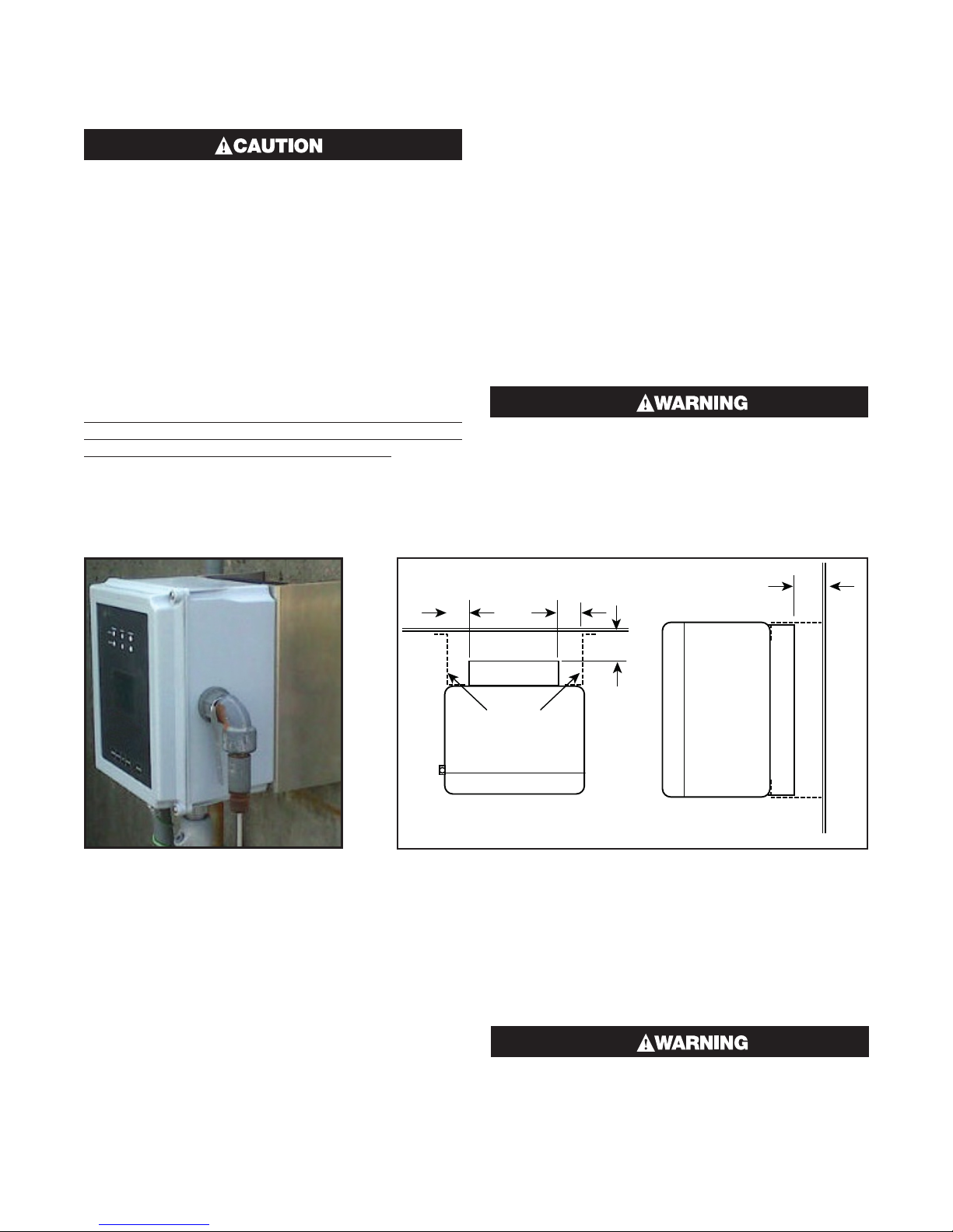
Should the owner decide not to use the provided brackets, mounting of the ITC must incorporate all of the following dimensional safeguards (Refer to Figure 2):
1. Maintain a minimum of 1.5” (3.8 cm) of free air space
on either side of the heat sink (K)
2. Maintain a minimum of 1.8” (4.6 cm) of free air space
directly behind the heat sink (C)
3. Zero air flow restriction above and below the heat
sink.
4. The mounting surface, customer mounting bracket
and fasteners must be of suitable structural design
to support four times the weight of the equipment.
Violating any of the heat sink clearance dimensions or if the equipment is used or mounted in
a manner not specified by Chromalox, the protection provided may be impaired. This could
result in equipment damage, personal injury or
both.
K K
Figure 1
Mounting Surface Considerations
The preferred materials of the mounting surface include metals, concrete or wood products. If the ITC
is to be mounted outdoors, then the metals shall have
corrosion resistant properties and the wood products
shall be treated for outdoor use. If the mounting surface is plaster (drywall), it shall be of the following minimum construction: 1/2”, +/-1/16” (10 mm, +/-2mm) in
thickness and supported by nominal 2” x 4” (50mm
x 100mm, +/-10 mm) studs that are on 16”, +/- 1/2”
(400mm, +/- 10mm) centers. See Dimensions section
for wall mount layout and hole location. Mounting shall
be performed by experienced professionals.
C
C
Heat Sink
Mounting
Brackets
Front
Top View of ITC
Controller
Figure 2
Front
Heat Sink
Right Side View
of ITC Controller
Fasteners
The fasteners shall be of 300 series (304 or 316) stainless steel and they shall be a #8 or #10 (or metric equivalent) bolt or screw configuration. If anchors are to be
used, ensure that they match the fastener specification.
Improper mounting may cause an unsafe condition resulting in equipment damage or failure
which could cause personal injury.
Mounting Surface
7
Page 8
Operating the ITC
Set Point T
HMI (Human – Machine Interface)
There are three areas on the front panel of the ITC in
which the User may visually receive information or provide input to the controller:
1. LED status indication for Power,
Load & Alarm for each circuit
2. Hi Resolution TFT displays the parameter settings,
alarm type, mode of operation, current load
demand, program menu screen
and menu selection items
3. Capacitive touch keypad
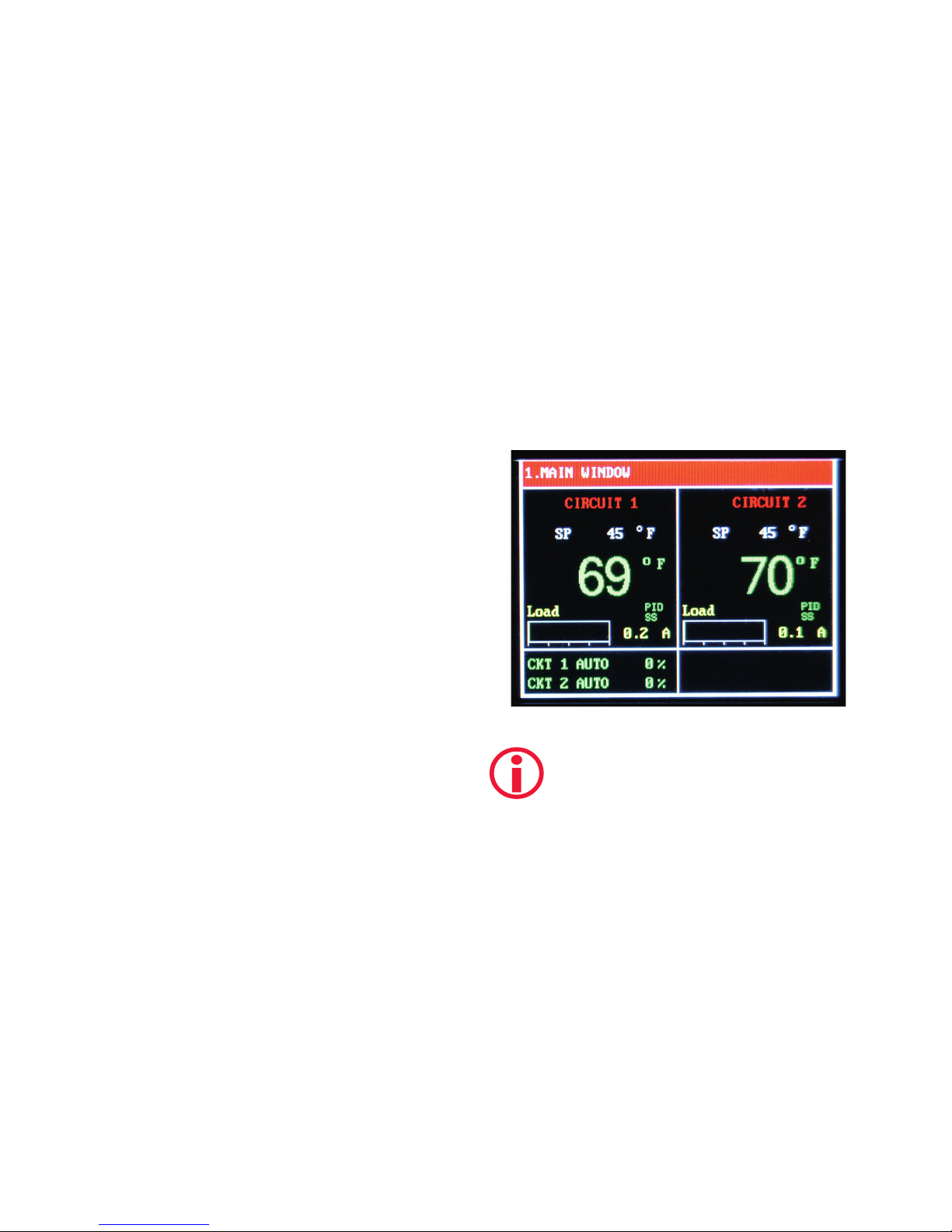
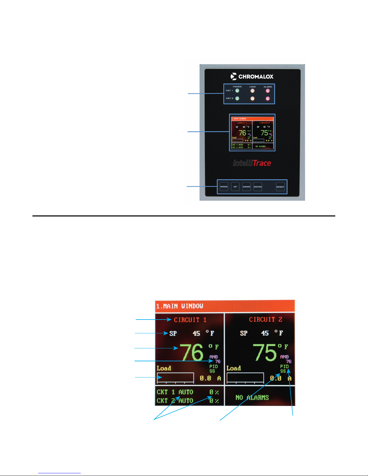
Main Window
In normal operating mode, the main window screen on
the ITC displays the circuit number, set point temperature, process temperature, current load demand, soft
start status, mode of operation, output % and alarm
type for each active circuit.
Below is the Main Window for a 2 Circuit ITC.
Circuit Number
emperature
Process Temperature
Ambient Temperature
Current Load,
Bar Graph & Value
Mode of Operation
& Output % per Circuit
Soft Start Status
8
Auto Mode Type
(PID or On/Off)
Page 9
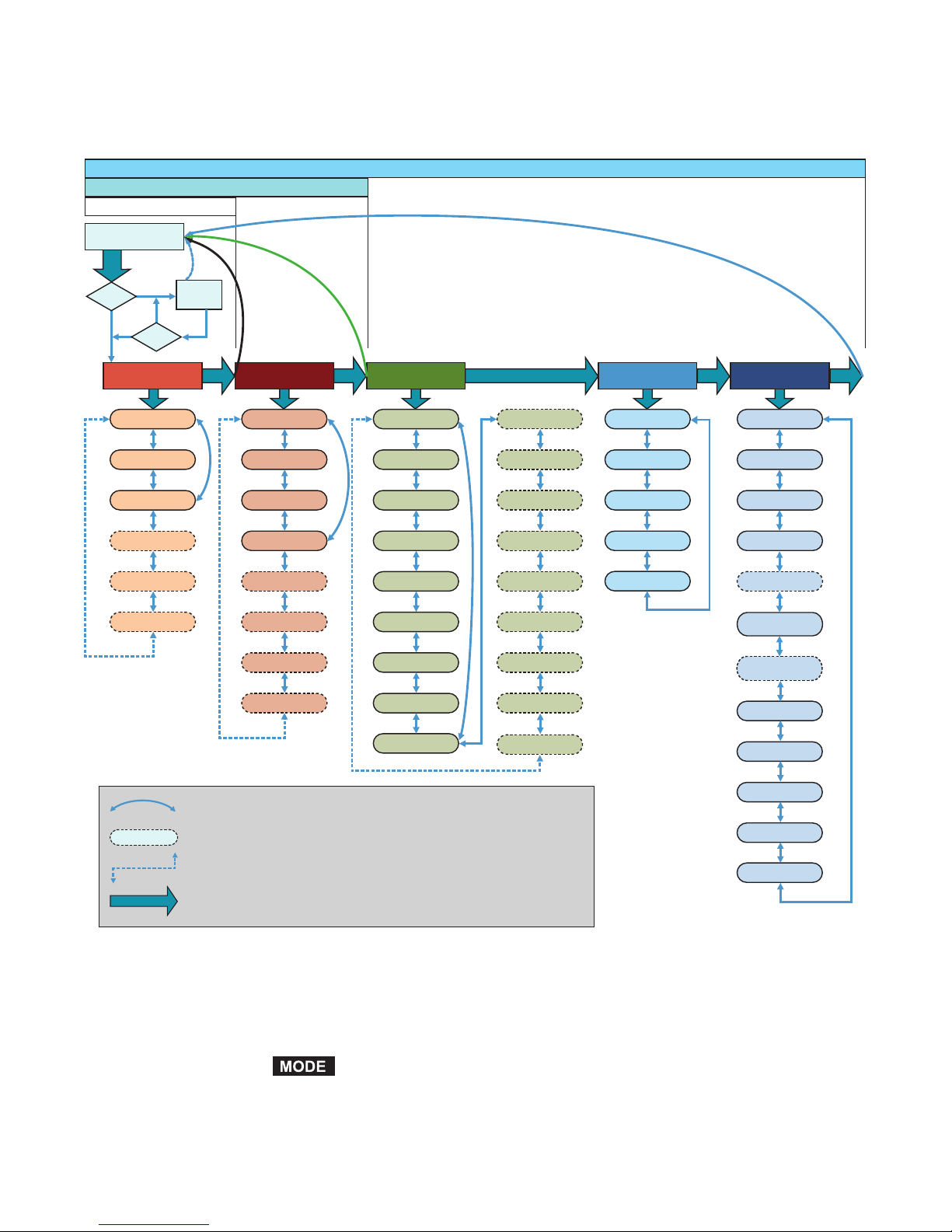
Navigating the ITC
Visually, here is how one navigates through the ITC Menus & Parameters:
Security Level 3
Security Level 2
Security Level 1
1. Main Window
Mode
No
Logged?
Yes
Yes
2. Login
No
Correct?
3. Temperature Menu
Temp Setpoint 1
Lo Temp Alarm 1
Hi Temp Alarm 1
Temp Setpoint 2
Lo Temp Alarm 2
Hi Temp Alarm 2
Mode Mode Mode ModeMode
Lo Current Alarm 1
Hi Current Alarm1
GFEP Setpoint 1
GFEP Alarm/Trip 1
Lo Current Alarm 2
Hi Current Alarm 2
GFEP Setpoint 2
GFEP Alarm/Trip 2
5. Control Menu
Auto Control Mode 1
Auto/Man/Off 1
Deadband 1
Autotune 1
Prop. Band 1
Integral 1
Rate 1
Soft Start 1
Manual Offset 1
Curved Double Arrow - continuation path for 1-Circuit Units Only
Auto Control Mode 2
Auto/Man/Off 2
Deadband 2
Autotune 2
Prop. Band 2
Integral 2
Rate 2
Soft Start 2
Manual Offset 2
6. Comms Menu
Baud Rate
Parity
Modbus ID
IP Address
DHCP
7. System Menu 4. Current Menu
Firmware Version
Button Sound
Units
Temp. Sensing 1
Temp. Sensing 2
Failed Sensor
Output 1
Failed Sensor
Output 2
Password Level 1
Password Level 2
Password Level 3
GFEP Alarm/Trip 2
Dashed Parameter Ovals appear on 2-Circuit Units Only
Dashed, Angled Connector - continuation path for 2-Circuit Units Only
Mode
Mode arrow represents pressing the MODE Key
The horizontal security level bars, which are above the
ITC Menu & Parameter navigation map, illustrate the
available menus within that security level. The Main Window is presented when the
Alarm State
Restore to Default
while the operator is at the last available menu screen
within the current security level.
button is selected
9
Page 10
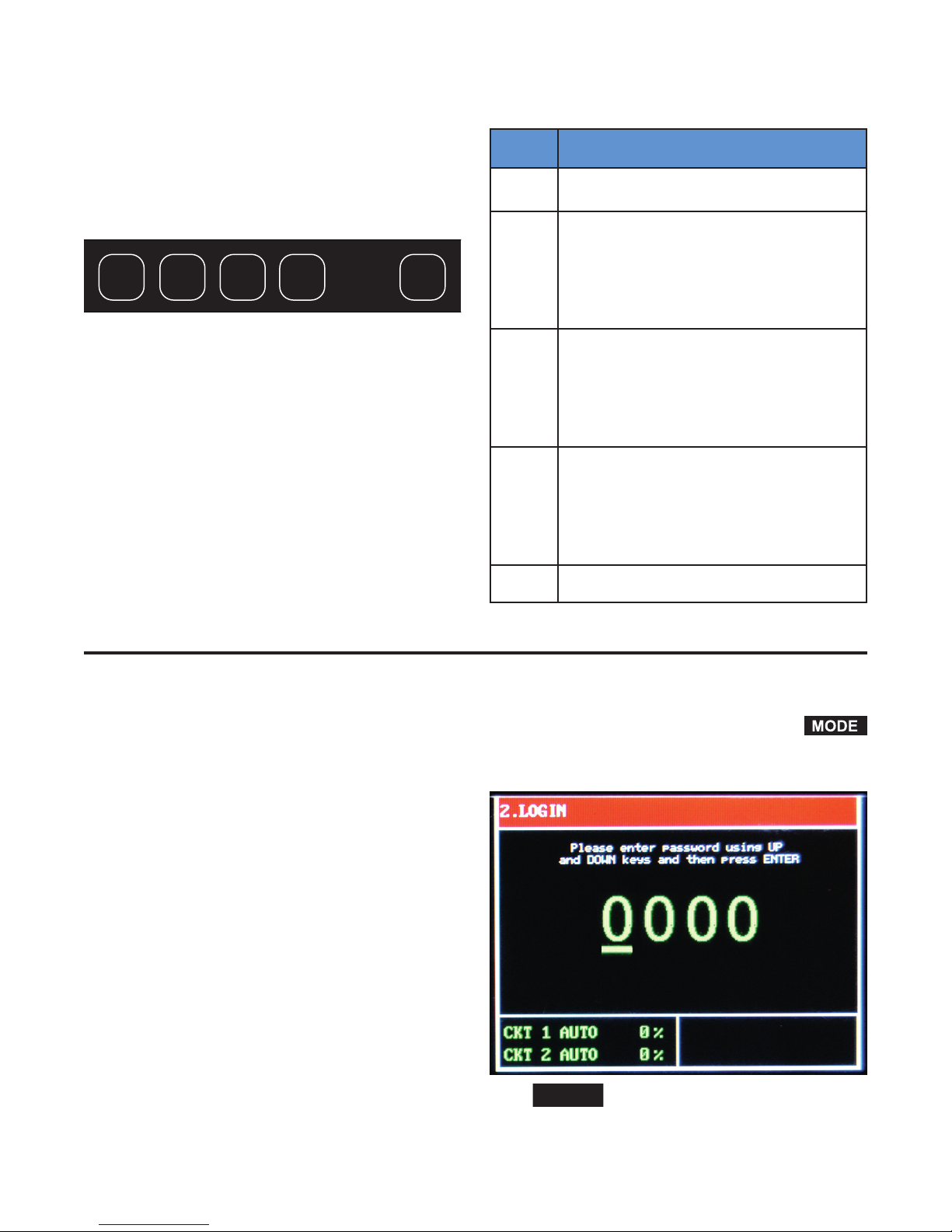
The Keypad
ENTER
RESET
There are five capacitive touch keys or buttons on the
front panel. The keypad allows the user to select or
change parameters & settings, clear alarms and navigate
throughout the ITC programming areas. See Figure 3
shown below:
MODE UP
DOWN
Figure 3
ENTER
RESET
The function of each key is as follows:
KEY FUNCTION
MODE
UP
DOWN
ENTER
Allows the user to Navigate between
Menus & Main Window
1. Within a Menu, Scroll UP to next Parameter or Setting within that Menu
2. When viewing an adjustable parameter
or setting, increments that parameter
UP to the next available value. For a
quick scroll, push and hold the key.
1. Within a Menu, Scroll DOWN to next
Parameter or Setting within that Menu
2. When viewing an adjustable parameter
or setting, increments that parameter
DOWN to the next available value. For a
quick scroll, push and hold the key.
1. To accept a parameter or setting that
has been entered or changed.
2. Press to accept the change when viewing an adjustable parameter or setting.
3. When in LOGIN Screen, press to advance to next security digit.
Programming the ITC
The ITC is pre-programmed with default parameters and
settings that allow it to function “right out of the box”.
To change any of the parameters or settings on the ITC,
you must access the appropriate menu(s): Temperature
Menu, Current Menu, Control Menu, Comms (communications) Menu or System Menu.
RESET
To access any of these menus, press the
button on the keypad. You will be presented with the
Login screen:
Resets or clears all alarms
10
Press
to advance to the next digit.
Page 11
Security Levels
You must first enter a passcode that is aligned with the
menu that you wish to access. In most cases, limited
access to certain programming areas is desired. The
most frequently used parameter settings have the lowest level of security. Invalid passcodes will not be accepted and you will be returned to the LOGIN Screen.
Initial factory set passcodes for the Security levels below are:
Security
Level Passcode
1 0011 Temperature Menu Only
2 0034
3 0063
Temperature & Current
Menus Only
Temperature, Current, Control,
Comms & System Menus
Available
Programming Menus
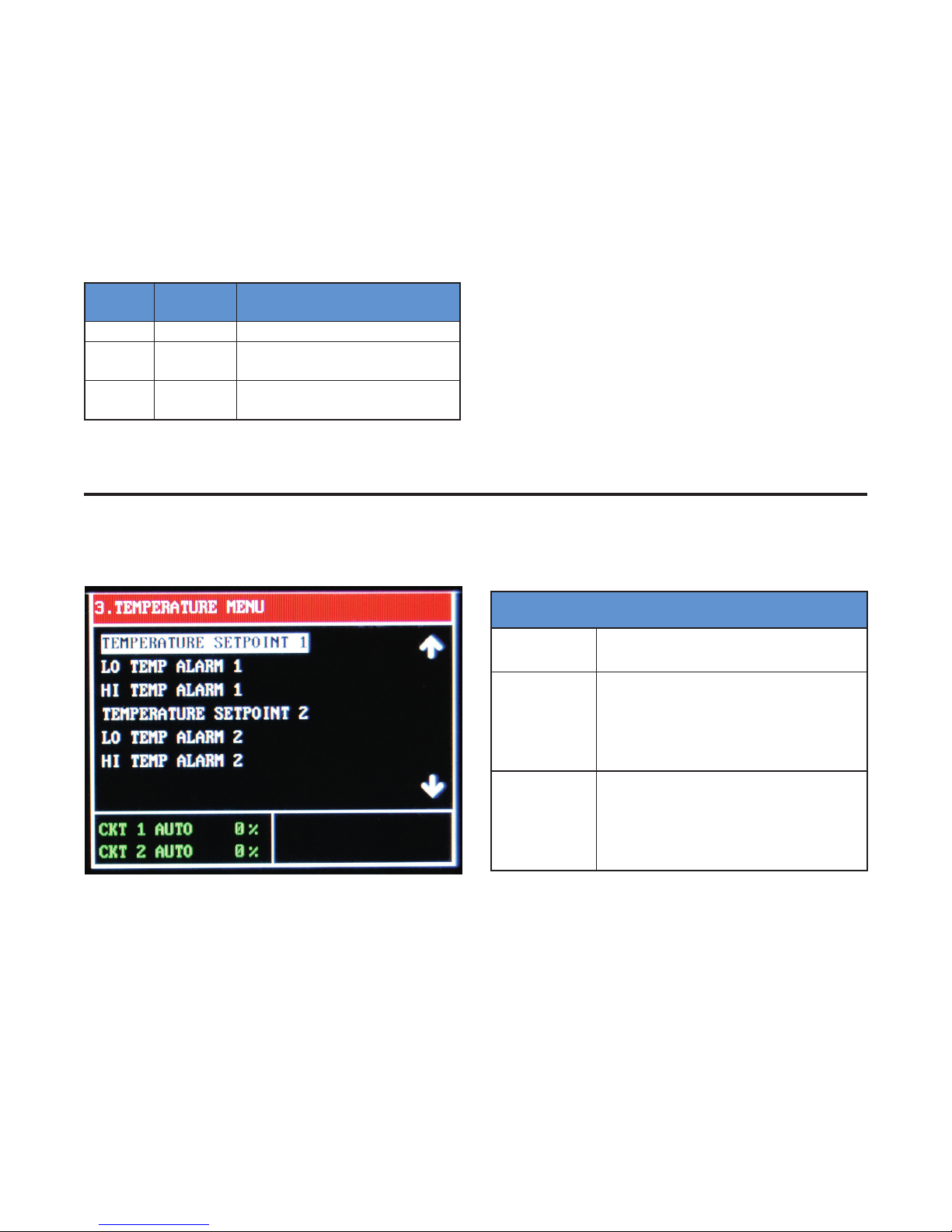
The Temperature Menu
Security Levels 1, 2 & 3
You will be returned to the main screen if no buttons
are depressed within a 30 second time frame.
Passcodes may be reprogrammed within the Systems
Menu. These codes should be kept in a secure place.
The Temperature Menu provides access to the Temperature based parameters: Temperature Setpoint,
Low Temperature Alarm & High Temperature Alarm for
Circuits 1 and 2 (when available).
3. Temperature Menu
Temperature
Setpoint
Low
Temperature
Alarm
High
Temperature
Alarm
Process Temperature Variable
Lower limit of the Process Temperature
Variable at which the system goes into
alarm state. This alarm may be turned
OFF by going one increment beyond
the Lowest setting.
Upper limit of the Process Temperature
Variable at which the system goes into
alarm state. This alarm may be turned
OFF by going one increment beyond
the Highest setting.
11
Page 12

The Current Menu
Security Levels 2 & 3
4. Current Menu
The Current Menu provides access to the current and
GFEP based parameters: Low Current Alarm, High
Current Alarm, GFEP Setpoint & GFEP Alarm/Trip for
Circuits 1 and 2 (when available).
Low
Current
Alarm
High
Current
Alarm
GFEP
Setpoint
GFEP
Alarm/Trip
Lower limit of the Load Current Variable at
which the system goes into alarm state.
This alarm may be turned OFF by going
one increment beyond the Lowest setting.
Upper limit of the Load Current Variable at
which the system goes into alarm state.
This alarm may be turned OFF by going
one increment beyond the Highest setting.
Upper limit of the Ground Fault Equipment
Protection Variable at which the system
goes into alarm state
Action taken by controller when the GFEP
Setpoint alarm condition is achieved.
The options are:
Output remains at
selected output %.
1. Alarm Only,
Non-Latching
2. Alarm & Trip,
Non-Latching
3. Alarm Only,
Latching
4. Alarm & Trip,
Latching
Alarm clears when
sensed GFEP cur
rent is 5mA < GFEP
setpoint
Output goes to 0%
(off) while in alarm
state. Alarm clears
when sensed GFEP
current is 5mA <GFEP
setpoint
Output remains at
selected output %.
Alarm condition may
only be cleared with a
manual reset.
Output goes to 0%
(Off) while in alarm
state. Alarm condition
may only be cleared
with a manual reset.
-
The Control Menu
Security Level 3
12
Page 13

The Control Menu provides access to the types of Automatic Control, Mode of Operation, the parameters which
influence the control algorithms and the Soft Start function: Auto Control Mode, Auto/Manual/Off Control, Dead-
band, Autotune, Proportional Band, Integral, Rate (Derivative), Soft Start function and Manual Offset.
5. Control Menu
Auto Control Mode
Auto/Manual/Off
(Mode of Operation)
Autotune
Deadband
When the ITC is in AUTO Mode (see AUTO/MANUAL/Off parameter), the choice of
Automatic Control is either PID or ON/OFF Mode.
Determines the type of Control Operation: Automatic, Manual or Off.
Automatic Control: Select Auto. This allows PID or On/Off control.
Manual Control: Select 1 – 100. This is the % power output.
Off: Select 0. This equates to 0% output, which turns off that circuit.
NOTE: The Soft Start function will only engage when the ITC is in AUTO Mode
The ITC Autotune function establishes the individual P, I & D (Proportional Band, Integral
& Derivative) control modes. These modes help to bring the process variable to the
setpoint temperature as quickly as possible.
In order to properly calculate the P, I & D modes, the Autotune program requires a 25
degree rise in sensed temperature after initiating the program. If within 30 minutes the
temperature will not reach its setpoint, the Autotune algorithm will be canceled and old
PID values will be used.
Once the Autotune feature is activated, you must not change the menu page until the
Autotune algorithm is completed. Changing the page will cause the Autotune algorithm
to shut down.
The Autotune function is a one-time algorithm set up of the P, I & D control modes.
Should your process variables change significantly, it is suggested to that the Autotune
feature be turned off and then reinitiated.
Active ONLY when the ITC is in Auto Mode & under On/Off Control
The temperature range equally divided above & below the temperature set point, where
the controller will not take corrective action.
Example: A setting of “10” for the deadband will result in a deadband that is 5 degrees
above and below the temperature setpoint.
Proportional Band, P
Integral, I
(Automatic Reset)
Derivative, D
(Rate)
Soft Start
Manual Offset
Active ONLY when the ITC is in Auto Mode & under PID Control
The Proportional Band (P), the Integral (I) & Derivative (D) are modes of control that work
in union to bring the process variable to setpoint as smoothly and quickly as possible.
The P, I & D will be automatically established during the Autotune procedure (see above).
Additionally, the P, I & D may all be manually established by the user. Great care should
be taken when manually establishing the P, I & D.
Proportional Band: The temperature range above and below the temperature set point.
Will only be available while the Mode of Operation is set to AUTO.
Options are On or Off.
Only available while the Mode of Operation is set to AUTO & under PID Control
The Manual Offset may be used in conjunction with the PID variables to assist in Tuning the controller. Typically, heat trace applications will not require any Manual Offset
adjustment.
Manual Offset allows the user to preprogram the approximate power output (%) requirement at the setpoint. This has been proven to reduce the time needed to align the
process temperature with the setpoint temperature. As a rule of thumb, relatively light
heating loads will require smaller Manual Offset values.
The Manual Offset is a percentage output with a range of 0 (0%) to 1000 (100%) and a
default of 500 (50%).
13
Page 14

The Soft Start Function
The Soft Start function is located within the Control
Menu page. The Soft Start function will operate independently on each circuit.
To limit inrush current on the overall system, an inherent characteristic of self-regulating/limiting heating cable, a proprietary Soft Start algorithm is applied during
system start-up. This will ONLY occur while the mode
of operation is set to AUTO and Soft Start feature is
turned ON. The Soft Start program will increment output by 1% every 1 second until the desired temperature is reached or the output % achieves 100%.
After the Soft Start program completes its cycle, the
Automatic Control Mode of the system will return to
either PID or ON/OFF control, depending on what was
selected by the user. The Soft Start Program will not
function if the control mode is set to Manual.
The Comms Menu (Communications)
Security Level 3
The Comms Menu provides access to the settings for
Serial Communications, Modbus RTU/RS-485 or the
optional TCP/Ethernet Communications. These communications settings include: Baud Rate, Parity, Modbus ID, IP Address and DHCP.
Modbus RTU requires that you know or define baud
rate, character format (Parity), and slave ID (aka slave
address, unit number, unit ID). A mismatch in any of
these will result in no communication. Likewise, an incorrect IP address will result in no communication on
an IP Network.
Note: See Modbus Communications Addendum for
detailed register addresses and other Modbus settings.
14
Page 15
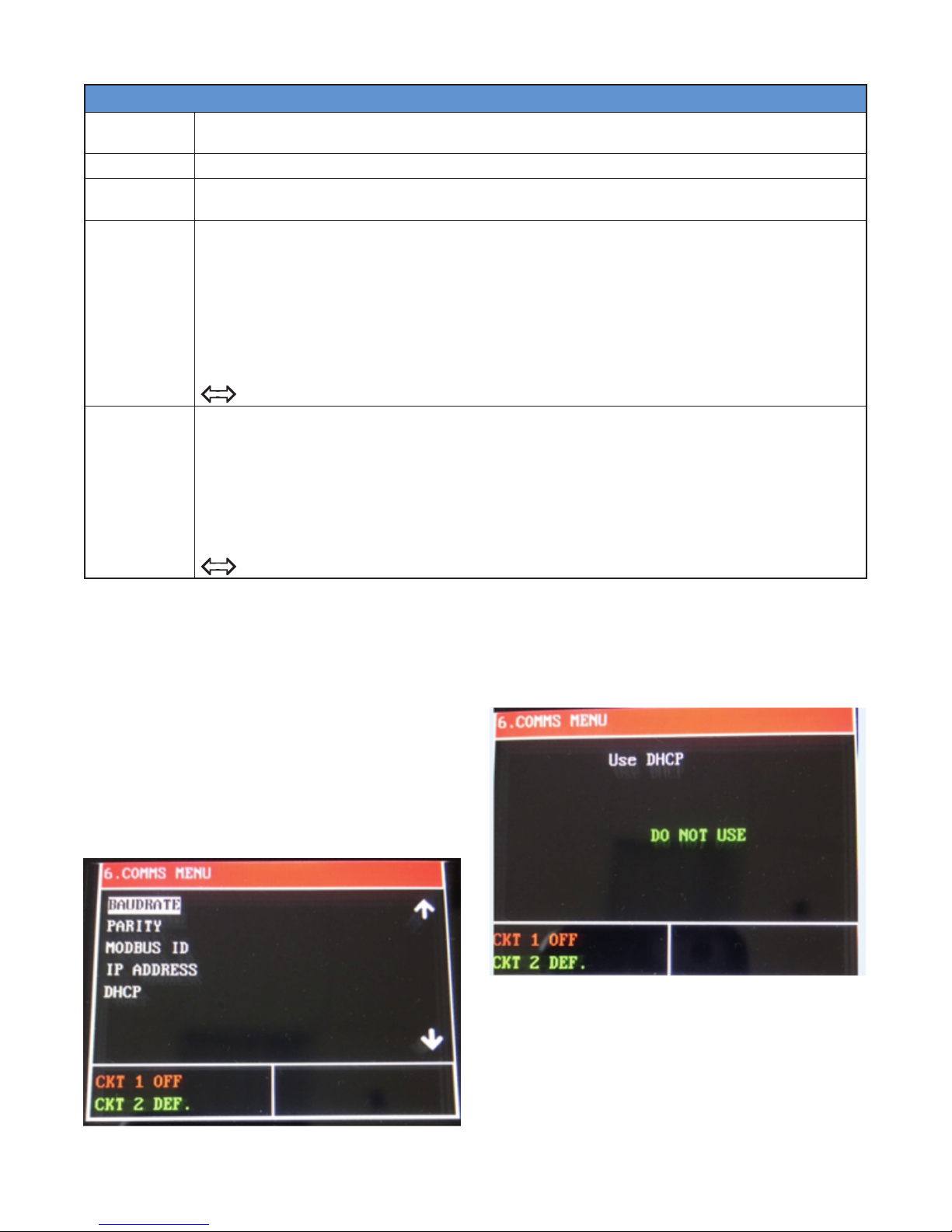
6. Comms Menu
Baud Rate
Data transmission speed in Serial Communications, in Hertz (Hz).
The range offered by the ITC is 2.4k, 4.8k, 9.6k, 19.2k, 38.4k, 56.0k
Parity The parity bit is to be set to NONE, EVEN or ODD.
ModBus ID
This is the Identification or Address of the ITC Unit on a Modbus Network. The ID shall be any
number from 1 to 255.
The Internet Protocol (IP) Address is the address or identifier of a device on a network, such as
Modbus TCP/Ethernet, which employs the internet protocol to communicate. Assignment of the
IP address may be accomplished in one of two ways:
1. Automatically assign (Default). (The DHCP Selection must be “USE”)
IP Address
The IP address will be automatically established via the customer’s DHCP.
2. Manually assign. (The DHCP Selection must be “DO NOT USE”)
Select “DO NOT USE” when in the DHCP menu, then enter the appropriate IP Address via
the UP/DOWN arrow keys & ENTER button to accept.
NOTE: One MUST cycle power to the unit AFTER changing the status of the DHCP (USE
DO NOT USE) and prior to obtaining a new IP Address.
DHCP (Dynamic Host Configuration Protocol) Status: Use or Do Not Use.
This impacts whether the IP Address is to be automatically assigned by the host DHCP Server
or manually entered by the operator. See IP Address above.
DHCP
USE – Select USE if you desire to have the IP Address automatically assigned to the unit by the
resident DHCP.
DO NOT USE – Select DO NOT USE if you desire to manually assign an IP Address to the ITC unit.
NOTE: One MUST cycle power to the unit AFTER changing the status of the DHCP (USE
DO NOT USE) and prior to obtaining a new IP Address.
Manually Assign IP Address (Static IP Address)
The factory default of the ITC is to have the IP Address
assigned automatically by the host DHCP Server. However, one may wish to manually assign or establish a
Static IP Address. Follow these instructions below to
accomplish this:
1. To manually assign the IP address (if not using
DHCP server), navigate to the COMMS menu by
logging in and then pressing the MODE key until the
COMMS menus is observed.
2. Use the DOWN or UP keys to navigate down to
DHCP within the COMMS menu, and then press
ENTER.
3. Use the DOWN or UP keys to toggle the selection
between USE and DO NOT USE. Make sure that
DO NOT USE is displayed, then press ENTER to
confirm selection.
NOTE: After pressing ENTER, power to the
controller must be cycled for the change in the
DHCP setting to take effect.
15
Page 16
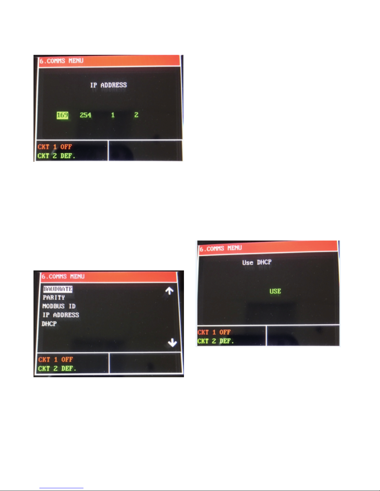
4. Use the DOWN or UP keys to highlight IP ADDRESS, then press ENTER key to edit the IP Ad-
dress:
Automatically Assign IP Address
a. The IP ADDRESS is composed of four fields,
each with a value range from 0 to 255.
b. Use the UP and DOWN keys to adjust a field val-
ue.
c. Use the RESET key to toggle between any of the
four fields being edited.
d. To complete and establish a new IP Address,
press the ENTER key to return to the COMMS
MENU.
As previously mentioned, the factory default of the ITC
is to have the IP Address assigned automatically by the
host DHCP Server. However, if the IP Address was obtained manually and now the desire is to have it established automatically from a DHCP server, the following
steps must be taken:
1. Navigate to DHCP within the COMMS menu, and
then press ENTER.
2. Use the DOWN or UP keys to toggle the selection
between USE and DO NOT USE. Make sure that
USE is displayed and then press ENTER to confirm
selection.
NOTE: After pressing ENTER, power to the
controller must be cycled for the change in the
DHCP setting to take effect.
16
Page 17
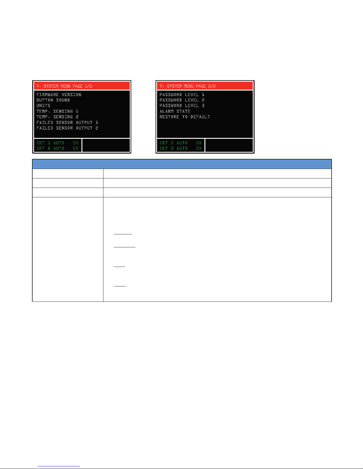
The Systems Menu
Security Level 3
The System Menu provides access to system information and system settings for the ITC. Items contained in the
System Menu include: Firmware Version of the ITC, Button Sound for Keypad interaction, Units (Temperature), Temperature Sensing Type, Failed Sensor Output, (Security) Password for Levels 1, 2 & 3, Alarm State (normally open or
normally closed) Restore to Default (Settings & Parameters).
7. SYSTEM MENU PAGE 1/2
FIRMWARE VERSION
B
UTTON SOUND
NITS
U
EMP. SENSING 1
T
EMP. SENSING 2
T
AILED SENSOR OUTPUT 1
F
F
AILED SENSOR OUTPUT 2
CKT 1 AUTO 0%
C
KT 2 AUTO 0%
7. SYSTEM MENU PAGE 2/2
PASSWORD LEVEL 1
P
ASSWORD LEVEL 2
ASSWORD LEVEL 3
P
LARM STATE
A
ESTORE TO DEFAULT
R
CKT 1 AUTO 0%
C
KT 2 AUTO 0%
7. System Menu
Firmware Version Identifies the Firmware Release of your ITC.
Button Sound The Button Sound may be kept ON or turned OFF
Units Temperature Units, Fahrenheit or Celsius
The ITC accepts up to two RTD inputs per channel. In Auto Control Mode, the output
of each circuit will function according to the Temp Sensing Setting. However, when
in Manual Mode, the Output will only consider the Output % as selected by the User.
The following settings and their respective function are available when in AUTO Mode:
• Single – Output is based on the sensed temperature of only one RTD sensor. The
2nd RTD Sensor is not recognized.
• Average – Output is based on the average sensed temperature of the two RTD Sen-
Temp Sensing 1
sors. If Average is selected and only one sensor is employed, the unit will sense
an open sensor. See Failed Sensor Operation below.
• Low – Output is based on the lowest sensed temperature of the two RTD Sensors.
If Low is selected and only one sensor is employed, the unit will sense an open
sensor. See Failed Sensor Operation below.
• High – Output is based on the highest sensed temperature of the two RTD Sensors.
If High is selected and only one sensor is employed, the unit will sense an open
sensor. See Failed Sensor Operation.
17
Page 18

Temp Sensing 2
The ITC accepts up to two RTD inputs per channel. In Auto Control Mode, the output
of each circuit will function according to the Temp Sensing Setting. However, when
in Manual Mode, the Output will only consider the Output % as selected by the User.
The following settings and their respective function are available when in AUTO Mode:
• Single – Output is based on the sensed temperature of only one RTD sensor. The
2nd RTD Sensor is not recognized.
• Average – Output is based on the average sensed temperature of the two RTD Sensors. If Average is selected and only one sensor is employed, the unit will sense
an open sensor. See Failed Sensor Operation below.
• Low – Output is based on the lowest sensed temperature of the two RTD Sensors.
If Low is selected and only one sensor is employed, the unit will sense an open
sensor. See Failed Sensor Operation below.
• High – Output is based on the highest sensed temperature of the two RTD Sensors.
If High is selected and only one sensor is employed, the unit will sense an open
sensor. See Failed Sensor Operation.
• Use RTD 1 to control both circuits - The output of circuits 1 & 2 will be governed
by the “RTD1 Input” sensor which is located on the Circuit 1 main ITC board.
Notes:
a. This option is only available on 2 circuit ITC’s
b. The RTD sensor must be connected to “RTD1 Input” on Circuit 1 Main ITC
Board. See customer wiring section.
**IMPORTANT CONSIDERATIONS**
The ITC assumes a failed sensor condition if the realized temperature is either below
-100˚F or above 1500˚F. A failed RTD sensor (shorted or open) will send a faulty sensed
temperature to the controller that exceeds these thresholds. Therefore, the user must
understand the output of the ITC when a sensor fails.
Failed Sensor Output
Passwords 1, 2 & 3
Alarm State
Restore to Default
Failed Sensor Operation
1. Single – In Failed (Open or Shorted) RTD condition, the ITC will switch to Manual
Mode. Output will be per specified % by user. Failed Sensor condition will be flashing on the LCD screen and alarm LED will illuminate.
2. Average (when using two RTDs per circuit)
a. Individual Failed RTD (Open or Shorted) – ITC Unit will operate in Auto Mode
with a Single Sensor. The temperature reading from the failed RTD sensor will be
ignored. Failed Sensor condition will be flashing on the LCD screen and alarm
LED will illuminate.
b. When both sensors fail, the ITC will switch to Manual Mode. Output will be per
specified % by user. Failed Sensor condition will be flashing on the LCD screen
and alarm LED will illuminate.
3. Low – Same as Average above.
4. High – Same as Average above.
When using a single RTD - The ITC will automatically switch into Manual Output Mode
when a Failed Sensor Condition is realized. The output % range is 0% to 100% in 1%
increments.
When using two RTDs, see Failed Sensor Operation above.
Default Security Level Passwords may be changed by the user within the System Menu.
See “Security Levels” above for more detail.
Select normal state of alarm. Choices include Normally Closed (default) or Normally
Open.
This operation allows the user to clear all custom settings and parameters and restore
the ITC to its original factory state.
18
Page 19

Current Sampling
All active loops are individually tested for 2 seconds
every 2 minutes. During the test, a current load value is
updated on the yellow bar located on the Main Window
Alarms
Any alarm condition will be displayed in the bottom
right corner of the Main Screen. Additionally, a red LED
will be illuminated on the front panel under “ALARM”.
Alarm Type Display Solution
Check if your RTD is correctly connected to the unit or damaged.
Open Sensor SENS #X ERROR
Shorted Sensor SENS #X ERROR
Low Temperature LO TEMP CKT #!
Alarm clears automatically. Output will switch to Default Mode. Replace RTD if necessary.
Check if your RTD is correctly connected to the unit or damaged.
Alarm clears automatically. Output will switch to Default Mode. Replace RTD if necessary.
Sensed temperature is below Lo Temp Alarm Setpoint. Alarm will be
cleared automatically when the sensed temperature is greater than
the Low Temperature Alarm Setpoint, + 5 deg
and a new GFEP current is automatically and continuously calculated. The Yellow Load LEDs will be illuminated during the sampling test.
The table below illustrates the different types of alarm
where “#” represents circuit number and “X” repre-
sents either sensor A or B
High Temperature HI TEMP CKT #!
High Load HI LOAD CKT #!
Low Load LO LOAD CKT #!
High GFEP HI GFEP CKT #!
Sensed temperature is above High Temp Alarm Setpoint. Alarm will
be cleared automatically when the sensed temperature is less than
the High Temperature Alarm Setpoint, - 5 deg
Sensed load current is above Hi Current Alarm Setpoint. Alarm will
be cleared automatically when the sensed current < Current Hi Setpoint – 0.5 Amp
Sensed load current is below Current Lo Setpoint. Alarm will be
cleared automatically when the sensed current > Current Hi Setpoint
+ 0.5 Amp
Sensed GFEP current is above the GFEP Hi Setpoint. Alarm will be
cleared automatically when the sensed current < Current Hi Setpoint
- 5 mA
19
Page 20
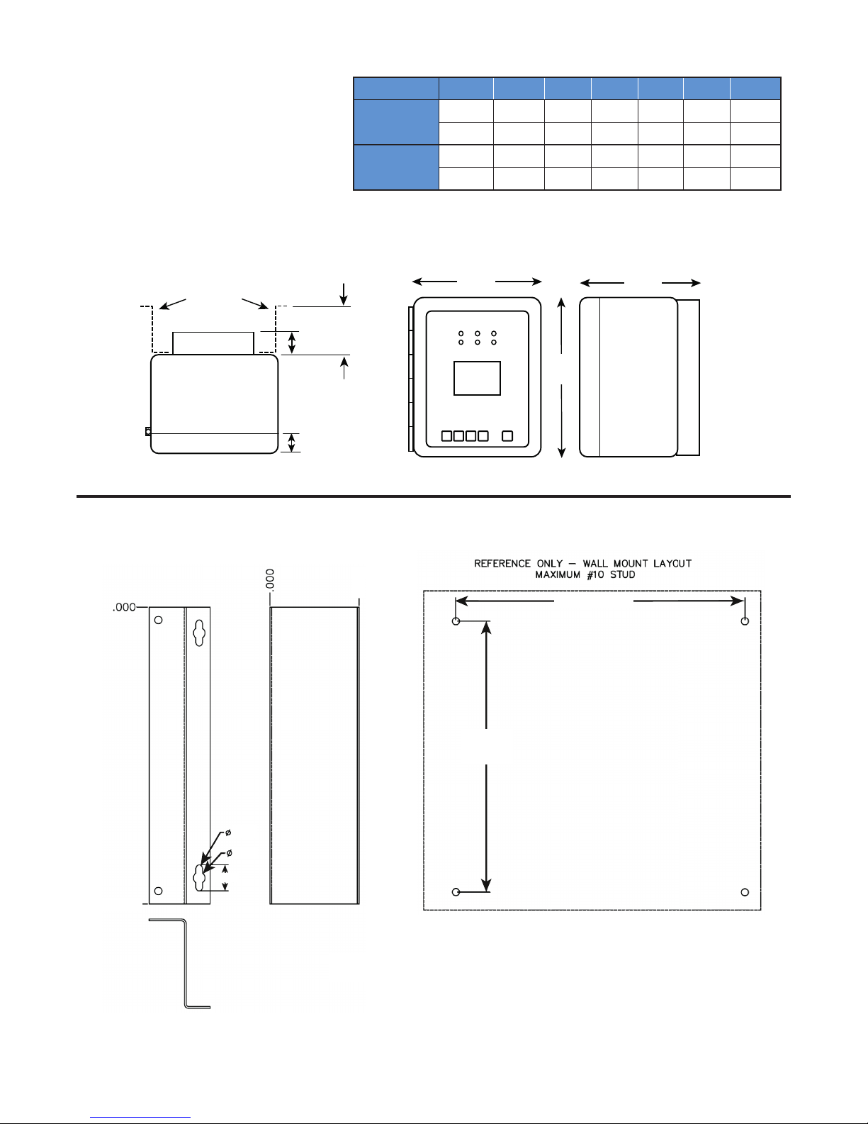
Dimensions
10
ITC Controller
316 SS
Enclosure
Fiberglass
Enclosure
H W D F B M
Inch 11.8 9.9 7.6 0.7 1.8 3.0
cm 30.2 25.1 19.4 1.7 4.4 7.6
Inch 10.3 8.5 8.0 1.2 1.8 3.0
cm 26.2 21.3 19.7 3.2 4.4 7.6
Mounting
Brackets
W
D
M
B Heat Sink
H
Heat Sink
F
Wall Mount Brackets
.000/11.813
(25.4/30.0)
.218
(0.55)
.390
(0.99)
.875 (2.2)
Dimensions are given for both enclosure types: Fiberlgas/316SS
(7.62)
3.000
8.250/10.188
(21.0/25.9)
Wall Mount Bracket Dimensions are in Inches
Wall Mount Bracket Dimensions are in Inches (cm)
8.750/10.625
(22.2/27.0)
20
Page 21

Default Settings
Below is the ITC parameter settings chart organized by Menu Screen. It includes the default, minimum, maximum
and / or the range of settings, where applicable.
The chart is for either 1 or 2 circuit units.
Parameter Defaults, Min., Max. & Range & User Settings
Screen Menu & Parameter
3. Temperature Menu Default Min. Max. Also User Settings
Temp Setpoint 1 45˚F -80˚F 1,100˚F
Lo Temp Alarm 1 40˚F -80˚F 1,050˚F Off
Hi Temp Alarm 1 180˚F -80˚F 1,150˚F Off
Temp Setpoint 2 45˚F -80˚F 1,100˚F
Lo Temp Alarm 2 40˚F -80˚F 1,050˚F Off
Hi Temp Alarm 2 180˚F -80˚F 1,150˚F Off
4. Current Menu Default Min. Max. Also User Settings
Low Current Alarm 1 0.1 A 0.1 A 50.0 A Off
Hi Current Alarm 1 40.0 A 0.1 A 50.0 A Off
GFEP Setpoint 1 30 mA 30 mA 150 mA
GFEP Alarm/Trip 1 Alarm Only Alarm Only, Alarm & Trip; Latching & Non Latching
Low Current Alarm 2 0.1 A 0.1 A 50.0 A Off
Hi Current Alarm 2 40.0 A 0.1 A 50.0 A Off
GFEP Setpoint 2 30 mA 30 mA 150 mA
GFEP Alarm/Trip 2 Alarm Only Alarm Only, Alarm & Trip; Latching & Non Latching
5. Control Menu Default Min. Max. Also User Settings
Auto Control Mode 1 PID On / Off PID
Auto / Manual / Off 1 Auto 0 100 Off
Deadband 1 10 2 100
Autotune 1 Off Off On
Proportional Band 1 20 1 100
Integral 1 500 0 9999
Rate 1 1 0 500
Soft Start 1 On Off On
Manual Offset 1 500 0 1000
Auto Control Mode 2 PID On / Off PID
Auto / Manual / Off 2 Auto 0 100 Off
Deadband 2 10 2 100
Autotune 2 Off Off On
Proportional Band 2 20 1 100
Integral 2 500 0 9999
Rate 2 1 0 500
Soft Start 2 On Off On
Manual Offset 2 500 0 1000
21
Page 22

Parameter Defaults, Min., Max. & Range & User Settings
Screen Menu & Parameter
6. Comms Menu Default Min. Max. Also User Settings
Baud Rate 9.6k 2.4k, 4.8k, 9.6k, 19.2k, 38.4k, 56.0k
Parity None Even Odd None
ModBus ID 1 1 255
IP Address Optional Feature
DHCP Use Use Do Not Use
7. Systems Menu Default Min. Max. Range User Settings
Firmware Version Current Firmware Version
Button Sound On Off On
Units Fahrenheit Fahrenheit Celsius
Temperature Sensing 1 Single Single, Average, Low, High
Temperature Sensing 2 Single
Single, Average, Low, High,
Use 1 RTD to control both circuits
Failed Sensor Output 1 50% 0% 100%
Failed Sensor Output 2 50% 0% 100%
Password Level 1
Password InputsPassword Level 2
Password Level 3
Alarm State
Normally
Closed
Normally
Open
Normally
Closed
Restore to Default Disabled Up / Down Up / Down
22
Page 23

Specifications
Input
Sensor Type 3-wire RTD, 100 W PT, 0.00385 W/W/˚C, 20 W balanced lead wire
Number of Sensor Inputs 1 or 2 per Circuit
Sensing Configuration Range: Single, Low, High, Average
Output
Power Switching SSR
Number of Circuits 1 or 2
Capacity 40 Amps per Circuit (Breaker size shall be 50 Amps maximum per
circuit or 125% of anticipated load)
Control Types
PID Control mode must be set to Auto
Autotune On or Off
Proportional Band, (˚F) Range: 1 – 100
Integral (sec/repeat) Range: 0 – 9,999
Rate or Derivative, (seconds) Range: 0 – 500
Manual Offset 0 - 1000 (0% - 100%)
On/Off Control mode must be set to Auto
Dead band, (˚F) Range: 2 – 100
Manual Range: 0 – 100%
Soft Start, Current Clamping Enable or Disable
Settings
Temperature (PV) Range: -80˚F to +1100˚F
Range: -62˚C to +593˚C
Low Temperature Alarm Range: -80˚F to +1050˚F, Off
Range: -62˚C to +566˚C, Off
High Temperature Alarm Range: -80˚F to +1150˚F, Off
Range: -62˚C to +621˚C, Off
Low Current Alarm Range: 0.1 A – 50.0 A, Off
High Current Alarm Range: 0.1 A – 50.0 A, Off
GFEP Range: 30mA – 150 mA, +/-2.5% of Span or +/- 3mA
GFEP Alarm Condition Alarm Only or Alarm & Trip
Output on Sensor Failure Mode Range: 0 – 100%, Bumpless Transfer to Manual Mode
Audible button depress Range: On, Off
Security 3 Levels of password protected security
Alarm State Normal Operation: Closed (default), Open
Display, HMI, Indication
Display 3.5” 320 x 240 RGB Full color graphic TFT module
Human Interface 5 Capacitive Touch Input Buttons
LED Indication Power (Green), Load (Amber), Alarm (Red) – Per Ckt
23
Page 24

Alarms
Alarm Types Low & High Temperature, Low & High Current, High GFEP,
Sensor Failure
Alarm Relays 1 x DC Alarm Output, 1.8 Amp, Customer Supplied 0 - 50 VDC
1 x AC Alarm Output, 1.8 Amp, Customer Supplied 12-240 VAC
Alarm Contact State
Mode Default Optional
Normal Operation Closed Open
Alarm Condition Open Closed
Power Off Open Open
Communications
ModBus RTU/RS485 (2 or 4 wire) & RTU/RS422, TCP/Ethernet
Baud Rate, Hz 2400, 4800, 9600, 19200, 38400, 56000
Parity Range: Even, Odd, None
ModBus ID Range: 1 – 255
DHCP Range: Use, Do Not Use
Ethernet IP Webserver over Ethernet
Operating & Environmental
Temperature -40˚F to 104˚F (-40˚C to 40˚C)
Humidity Relative Humidity 0% to 90%
Power Supply
100-277 Vac 50/60Hz
Protection IEC IP66
Enclosure Rating NEMA 4X FG
Approvals UL/cUL Ordinary and Class I, Division 2, Groups A,B,C,D Hazardous loca-
tions (UL file Number: E347725), CE
Temperature Rating T4
24
Page 25

Equipment Ratings
Field Wiring
Voltage Rating: ........................
Current Rating: .............................. 40 amps per Circuit
Number of Circuits .............................................. 1 or 2
Ambient Temperature Rating: ..............-40°F to +104°F
Altitude Rating: ......................Fully rated up to 6,500 Ft
VA consumption rating on electronics:............... 6.0 VA
The electronics are protected by a 0.5 Amp 350 VAC
2AG fuse.
Maximum RTD output ...............1.25 volts, 7 milliamps
Pollution Rating .............................................. Degree 2
Over Voltage ..............................................Category III*
* Overvoltage note: Category III is maintained only when a UL
Listed VZCA type 2 surge protector is employed between the
power source and the ITC unit. The surge protector must be
rated at 277 Vac (min) with a maximum surge protection rating of
2500 Vpk. Otherwise the ITC is rated at overvoltage Category II.
100-277 VAC, 50/60 Hz
(-40°C to +40°C)
(2,000 Meters)
Considerations
Torque values for line/load wiring
terminals: .................................................. 10-13 in/lbs.
(1.1-1.5 N-m)
Torque values for RTD 1 & 2 wiring
terminals: ...................................................... 6-8 in/lbs.
(.67-.90 N-m)
Torque values for shield grounding/alarm wiring
terminals: ...................................................... 3-4 in/lbs.
(.33-.45 N-m)
Terminal Block Gauge Range:
Line & Load .................................6-18 AWG, Copper
Alarm & Sensor ........................................12-24 AWG
Power Wire Rating
Max Load Min Breaker Size (AWG, 90˚C)
40A 50A 8
30A 40A 10
20A 25A 12
15A 20A 14
Modbus Wiring
Considerations
Environmental influences such as EMI/RFI can compromise the communication signal. Properly designed
cables will minimize their influences.
RS485 Max Length ............................. 2,500 ft. (800 m)
RS485 Wire Specification ......... T1/E1/DSL compatible
Example Vendor ..................L-Com (www.L-com.com)
Vendor Item ....................................................TSC9928
25
Page 26

Customer Wiring
RTD 2A RTD 2B
2-Circuit Ambient Sensing Control:
T
Sensor
Circuit 1 Main ITC Boar
d
Power, Heater, Alarms & Sensors
These connections are facilitated via the main ITC Board(s)
SENSOR
INPUTS
COM
–
RTD 1
INPUT
+
COM
–
RTD 2
INPUT
+
Only
Shield
Ground
o control both circuits with one RTD, the
MUST be wired to RTD 1A INPUT on
d
RTD 1A RTD 1B
Only
Shield
Ground
Upper board
applicable on 2
circuit units only
SENSOR
INPUTS
Circuit 2
Main ITC Board
EARTH
Max 40 Amps
HEATER
LOAD
HEATER
AC INPUT
100-277 VAC
AC HIGH
Breaker must be
rated at 125% of
max heater load,
but not to exceed
50 Amps
AC LOW
RTD Wiring
+
White
Red
Com
-
Re
COM
–
RTD 1
INPUT
+
COM
–
RTD 2
INPUT
+
LOAD
Customer Supplied
Shield
Ground
DC
0 - 42 VDC
Only
Shield
+ –
DC
ALARM
ALARM
OUTPUTS
Circuit 1
(RBF Type RTD Sensor)
Main ITC Board
AC INPUT
100-277 VAC
EARTH
Only
Ground
LOAD
AC
ALARM
AC
12 -240 VAC
Customer Supplied
HEATER
LOAD
Max 40 Amps
AC LOW
HEATER
AC HIGH
26
Breaker must be
rated at 125% of
max heater load,
but not to exceed
50 Amps
Page 27
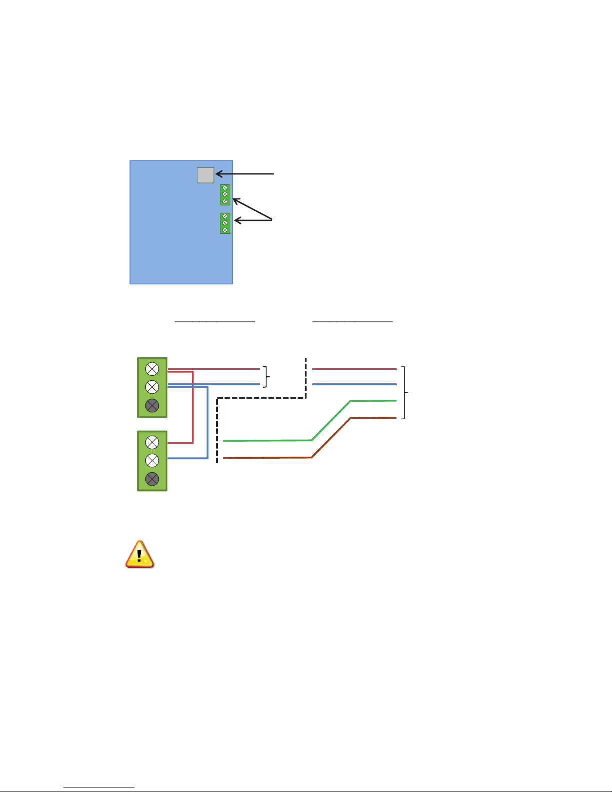
Modbus TCP/Ethernet or Web Server/Ethernet
RX+
Communications
These connections are facilitated via the Display Board.
(when ordered) uses the RJ45 connector
RX-
N/A
TX+
TX-
N/A
Display
Board
RS485 2-Wire
Must Jumper
(RX+/TX+) & (RX-/TX-)
The lowest pin on the Green terminal blocks has no use
Modbus RTU/RS485 or /RS422 use the
Green Terminal Blocks (Detail Below)
RS422 4-Wire
Use RX+, RX-, TX+ & TX-
RS485
2 Wire
RS422
4 Wire
All other Display Board connectors are for factory use
ONLY. Connection to these may damage the ITC Unit
27
Page 28

Modbus Addendum
MODBUS
Modbus Serial Communications
The ITC supports Modbus serial communications. For
a complete description of the Modbus protocol refer to
the description provided at http://www.modicon.com/
or http://www.modbus.org/
Physical Layer
The Base address, bit rate and character format are
configured via menu interface.
Physical layer configuration settings possible are:
Data rate: 2400, 4800, 9600 (default), 19200,
38400, 56000 bps
Parity: None (default), Even, Odd
Character format: Always 8 bits per character.
The transmitter must not start transmission until 3
character times have elapsed since reception of the
last character in a message, and must release the
transmission line within 3 character times of the last
character in a message.
Note: Three character times = 1.5ms at 19200, 3ms at
9600, 6ms at 4800, 12ms at 2400
Link Layer
A Query (or command) is transmitted from the Modbus
Master to the Modbus Slave. The slave instrument assembles the reply to the master. All of the instruments
covered by this manual are slave devices, and cannot
act as a Modbus Master.
SLAVE
MASTER
INSTRUMENT
QUERY
A message for either a QUERY or RESPONSE is made
up of an inter-message gap followed by a sequence of
data characters. The inter-message gap is at least 3.5
data character times.
Data is encoded for each character as binary data,
transmitted LSB first.
For a QUERY the address field contains the address
of the slave destination. The slave address is given
together with the Function and Data fields by the Application layer. The CRC is generated from the given
address, function and data characters.
For a RESPONSE the address field contains the address of the responding slave. The Function and Data
fields are generated by the slave application. The CRC
is generated from the address, function and data characters.
The standard MODBUS RTU CRC-16 calculation employing the polynomial 216+215+22+1 is used.
Intermessage
gap
Device Addressing
The instrument is assigned a unique device address
by the user in the range 1 (default) to 255. To change
Modbus address, navigate to page 6 of the ITC Menu
page and select “MODBUS ID” parameter. Use Up and
Down keys to change the value. This address is used
to recognize Modbus Queries intended for this instrument. The instrument does not respond to Modbus
Queries that do not match the address that has been
assigned to it.
The instrument will also accept global Queries using
device address 0 no matter what device address is
assigned. No responses are returned for globally addressed Queries.
Address
1 char.
Function
1 char.
Data n
char.
CRC
Check 2
char.
RESPONSE
Figure 1. Modbus Link Layer
28
Page 29

Description of Modbus Register Set
Modbus defines several function types; these instruments support the following types:
Table 1 - Modbus Function Code Set
Function Code Function Name
03 Read Holding Registers
04 Read Input Registers
06 Write Single Holding Register
16 Write Multiple Holding Registers
Input Registers
Table 2 - ITC-FS 1&2 Circuit Input Registers
Address Description Comments
30000 Sensed Temperature Ckt 1 Sensed Temperature Circuitl 1
30001 Setpoint Ckt 1 Setpoint Circuit 1
30002 Sensed ground fault current on Ckt 1 Sensed ground fault current on circuit 1
30003
Sensed load on Ckt 1 (expressed as integer
number ion tenths of Amp e.g. 154 = 15.4 Amp)
Sensed load on circuit 1 (expressed as integer
number ion tenths of Amp e.g. 154 = 15.4 Amp)
30004 Control Output Command on Ckt 1 Control Output Command on Circuit 1
30005 Sensed Temperature on Ckt 2 Sensed Temperature on Circuit 2
30006 Setpoint circuit 2 Setpoint circuit 2
30007 Sensed ground fault current on Ckt 2 Sensed ground fault current on circuit 2
30008
Sensed load on Ckt 2 (expressed as integer
number ion tenths of Amp e.g. 154 = 15.4 Amp)
Sensed load on circuit 2 (expressed as integer
number ion tenths of Amp e.g. 154 = 15.4 Amp)
30009 Control Output Command on Ckt 2 Control Output Command on Circuit 2
30010 Sensed Ambient Temperature Sensed Ambient Temperature
30011 Reserved
30012 Reserved
30013 Reserved
30014 Reserved
30015 Reserved
30016 Reserved
30017 Reserved
30018 Firmware ver CPU 1
30019 Firmware ver CPU 2
29
Page 30

Holding Registers
Table 3 - ITC-FS 1&2 Circuit Holding Registers
Address Description Range Comments
40000 Units 0-1 0-F; 1-C
40001 Setpoint Circuit 1 -80-1100 Expressed as an integer number
40002 Setpoint Circuit 2 -80-1100 Expressed as an integer number
40003 Control Mode for Circuit 1 0-1 0=PID; 1=ON/OFF
40004 Control Mode for Circuit 2 0-1 0=PID; 1=ON/OFF
40005 Deadband 1 0-10 Expressed as an integer number
40006 Deadband 2 0-10 Expressed as an integer number
40007 Commanded Power Ckt 1 0-100 & 101
40008 Commanded Power Ckt 2 0-100 & 101…
Expressed as an integer number e.g 50= 50%
(101= Circuit in AUTO mode)
Expressed as an integer number e.g 50= 50%
(101= Circuit in AUTO mode)
40009 Hi Temp Alarm for Ckt 1 -80 - 1150 Expressed as an integer number
40010 Hi Temp Alarm for Ckt 2 -80 - 1100 Expressed as an integer number
Bit state: 1 -alarm , 0 -no alarm
Bit # 1 - Sensor 1A Error
Bit #2 - Hi Temp Ckt 1 Alarm
Bit #3 - Lo Temp Ckt1 Alarm
40011 Alarm Register Ckt 1 0
Bit #4 - GFEP Ckt 1 Alarm
Bit #5 - Lo Current Ckt1 Alarm
Bit #6 - Hi Current Ckt1 Alarm
Bit #7 - Reserved
Bit #8 - Sensor 1B Error
Bit state: 1 -alarm , 0 -no alarm
Bit # 1 - Sensor 2A Error
Bit #2 - Hi Temp Ckt 2 Alarm
Bit #3 - Lo Temp Ckt2 Alarm
40012 Alarm Register Ckt 2 0
Bit #4 - GFEP Ckt 2 Alarm
Bit #5 - Lo Current Ckt2 Alarm
Bit #6 - Hi Current Ckt2 Alarm
Bit #7 - Reserved
Bit #8 - Sensor 2B Error
40013 Proportional Band Ckt 1 1-100 Expressed as an integer number
40014 Proportional Band Ckt 2 0-100 Expressed as an integer number
40015 Integral for Ckt 1 0-100 Expressed as an integer number
40016 Integral for Circuit 2 1-100 Expressed as an integer number
40017 Derivative for Ckt 1 0-500 Expressed as an integer number
40018 Derivative for Ckt 2 0-500 Expressed as an integer number
40019
40020
Low Temp Alarm Threshold for
Ckt 1
Low Temp Alarm Threshold for
Ckt 2
-80 - 1150 Expressed as an integer number
-80 - 1150 Expressed as an integer number
0 - 240
1 - 480
40021 Baudrate 0-4
2 - 9600 (default)
3 - 38400
4 - 56000"
30
Page 31

Address Description Range Comments
0 - NONE
40022 Parity 0-2
1 - EVEN
2 - ODD
40023 Modbus Slave Address 0-255 Expressed as an integer number
40024 Reserved
40025
40026
40027
GFEP Alarm Threshold for
Ckt 1
Low Current Alarm for
Ckt 1
HI Current alarm for
Ckt 1
30-150
0.0- 100.0
0.0 – 100.0
Expressed as an integer number
(in mA e.g. 75 = 75mA)
Expressed as an integer number in tenths of
Amp (e.g. 250 = 25.0 Amp)
Expressed as an integer number in tenths of
Amp (e.g. 250 = 25.0 Amp)
0 - Alarm Only, non latching
40028 GFEP Alarm behavior Ckt 1 0-3
1 - Alarm and Trip, non latching
2 - Alarm and Trip, Latching
3 - Alarm Only, Latching
40029 Reserved
40030
40031
GFEP Hi Alarm Threshold for
Circuit 2
Low Current Alarm for
Circuit 2
30-150
1.0- 100.0
40032 HI Current alarm for Circuit 2 0.0 – 100.0
40033 Soft Start Circuit 1 0-1
40034 Soft Start Circuit 2 0-1
Expressed as an integer number
(in mA e.g. 75 = 75mA)
Expressed as an integer number in tenths of
Amp (e.g. 250 = 25.0 Amp)
Expressed as an integer number in tenths of
Amp (e.g. 250 = 25.0 Amp)
0 - No
1 - Yes
0 - No
1 - Yes
0 - Alarm Only, non latching
40035 GFEP Alarm behavior Ckt 2 0-3
1 - Alarm and Trip, non latching
2 - Alarm and Trip, Latching
3 - Alarm Only, Latching
0 - Controller will take the highest reading out of
two RTDs (1A and 1B)
1 - Controller will take the lowest reading out of
two RTDs (1A and 1B)
2 - Controller will take the average reading out
of two RTDs (1A and 1B)
40036
Temperature sensing
( Circuit 1)
0-4
3 - Controller will use RTD # 1A
4- Controller will use one RTD 1A to control both
circuits
0 - Controller will take the highest reading out of
two RTDs (2A and 2B)
1 - Controller will take the lowest reading out of
40037 Temperature sensing (Circuit 2) 0-3
two RTDs (2A and 2B)
2 - Controller will take the average reading out
of two RTDs (2A and 2B)
3 - Controller will use RTD # 2A
40038 Default output 1 0-100% Expressed as an integer number (e.g. 75 = 75%)
40039 Default output 2 0-100% Expressed as an integer number (e.g. 75 = 75%)
40040 Reserved
40041 Reserved
31
Page 32

Service Contact
Information
Chromalox is a global supplier, providing the highest
level of customer support. If you should have questions
concerning your intelliTRACE™ ITC Controller or need
information, you may contact Chromalox at:
Corporate Headquarters
Chromalox, Inc.
103 Gamma Drive
Pittsburgh, PA 15238
Phone: (412) 967-3800
Customer Service Hotline: 1-800-443-2640
For application questions, you can:
1. Call one of our application engineers for personal
assistance at 1-888-996-9258.
2. Visit the technical reference section of our website
at www.chromalox.com for downloadable manuals
in PDF format.
Please refer to the Chromalox limited warranty applicable to this product at
http://www.chromalox.com/customer-service/policies/termsofsale.aspx.
© 2018 Chromalox, Inc.
Limited Warranty:
Chromalox, Inc.
1347 Heil Quaker Boulevard
Lavergne, TN 37086
(615) 793-3900
www.chromalox.com
32
 Loading...