

Page 1
(Supersedes PF443)
PF443-1
ICH
161-511739-001
OCTOBER, 2004
4
Type ICH Convection Heater
© 2010 Chromalox, Inc.
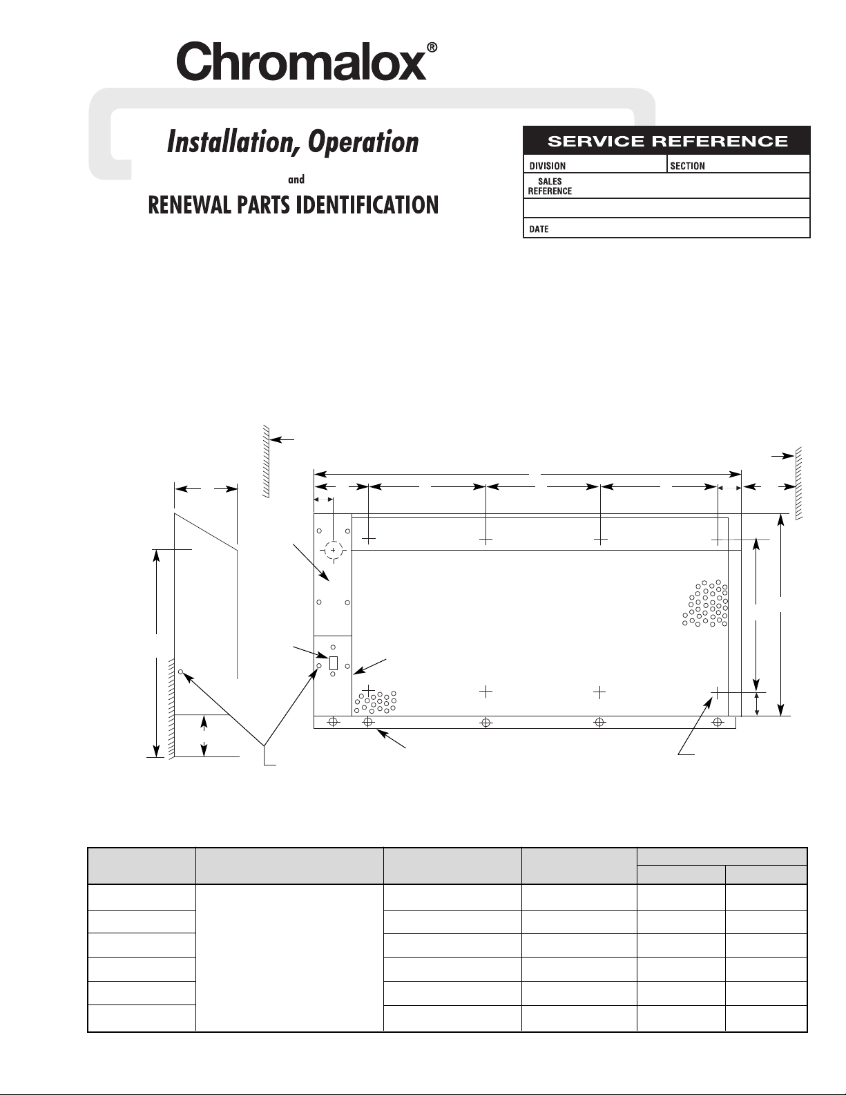
Specifications
Adjacent wall
or other obstruction
Adjacent wall or
other obstruction
Top
Access
Cover
Lower Case
Assembly
On-Off
Switch
Mounting holes 11/32" dia.
for mtg. front cover to wall
Tamper Proof
Screws 10 - 32 x 1/2"
Center line of
1-3/32" dia. hole
in rear panel
for customer
entry.
1"
min.
Mounting holes
11/32" dia. for mtg.
rear panel to wall
1 / "
3
4
NOTICE: Carefully remove heater from carton and
check for shipping damage. Any damage claims
should be entered immediately with the carrier.
DANGER: This heater is not intended for use in
hazardous atmospheres where flammable vapors,
gases, liquids or other combustible atmospheres
are present as defined in the National Electrical
Code. Failure to comply can result in explosion or
fire.
Dimensions (In.)
Model Voltage Wattage Phase A B
ICH-18025 250 1 18 12
ICH-28050 500 1 28 22
ICH-38075
120, 208, 240, 277
750 1 38 16
ICH-45100 1000 1 48 14
ICH-60125 1250 1 60 18
ICH-72100 1500 1 72 16
1
/2
19”
Min.
6” to floor min.
5”
4” B B
B
A
1”
min.
10”
16”
3”
Page 2
WARNING: Hazard of Electric Shock. Disconnect all
power before installing heater.
1. Locate on vertical wall with length of heater positioned horizontally.
2. When selecting a mounting location, the following minimum
distances must be observed to insure proper operation.
A. Six (6”) inches from bottom of heater to floor.
B. One (1”) inch from wall or other obstruction to the right or
left side of heater.
3. Do not mount heater in a recess, since such mounting interferes
with free air circulation, increases temperatures and prevents
proper thermostat operation.
4. Mount the rear panel assembly of the heater to the wall using
the
11
/32” dia. holes (bolts to be supplied by customer).
5. Install the perforated cover by hooking the top edge of the
cover over the top edge of rear panel.
6. Attach the bottom lip of the perforated cover to the wall using
the
1
/4-20x1” tamper proof screws.
7. On lower cover assembly connect wires T1-T1 and T2-T2 with
wire nuts provided. Install cover assembly with (2) 10-32x
1
/2
and (1) 1/4-20x1” tamper proof screws. Use special magnetic
bits provided. (Use standard
5
/16 socket or variable speed drill
when attaching screws.
8. Wire power lines to pigtail leads marked L1 and L2. Connect
ground wire to the green pigtail lead.
9. Adjust thermostat to the desired setting. Install top access
cover with (4) 10-32x
1
/2 tamper proof screws using spanner
tool bits provided.
MOUNTING
WARNING: Hazard of Electrical Shock. Any installa-
tion involving electric heaters must be grounded to
earth to eliminate shock hazard.
Note: Electrical wiring is to be in accordance with National
Electrical Code and local codes using at least 75°C (167°) type
RH, THW or equivalent insulated wire.
1. Electrical wiring must be brought into heater through
13
/32” dia.
hole located in the rear panel.
2. Grounding conductor with green insulation must be connected
to the green pigtail lead.
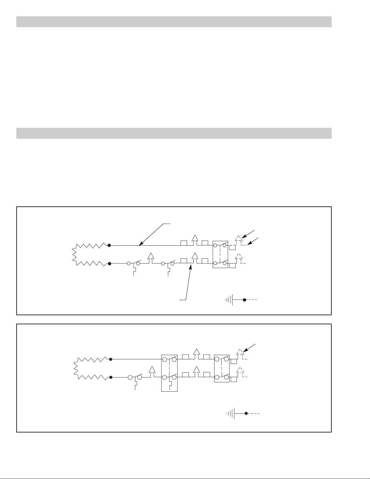
3. Make the proper connections using the appropriate wiring diagram below. Use diagram A for 120 and 277V heaters and use
diagram B for 208 and 240V heaters. These diagrams apply to
all size heaters.
WIRING
White Wire
Heating
Element
Auto
Cutout
T'Stat
Black Wire
Disconnect
Switch
Grd (Green)
Wire Nuts
Common
120 277V
1ø
Power
Circuit
T2
T2
T1
T1
L2
L1
Heating
Element
Auto
Cutout
Double
Pole
T'Stat
Disconnect
Switch
Wire Nuts
208 240V
1ø
Power
Circuit
Grd (Green)
T2
T1
T2
T1
L2
L1
Wiring Diagram A
Wiring Diagram B
Page 3

OPERATION
DANGER: Hazard of Fire. Keep combustible materi-
als and temperature sensitive fabrics at least 4”
away from front of cover or above cover.
WARNING: Users should install adequate back-up
controls and safety devices with their electric
heating equipment. Where the consequences of
failure may be severe, back-up controls are essential. Although the safety of the installation is the
responsibility of the user, Chromalox will be glad to
make equipment recommendations.
MAINTENANCE
WARNING: Hazard of Severe Shock. Disconnect all
power to heater before servicing or replacing
heaters.
1. Following long periods of idleness, heater should be vacuumed
before start-up, to remove accumulated combustible particles
which will incinerate causing smoking and consequent wall
discoloration.
2. If heater is located in areas of heavy traffic, furnish suitable
heater guard (wall mounted pipe rail in front of case, for example) to prevent damage to heater.
RENEWAL PARTS IDENTIFICATION
Model Volts Watts Heating Element Switch Thermostat Overtemp Cut-Out Front Case
120 250 118-553632-001 292-511857-001 300-049198-001 300-053610-001 080-511673-001
ICH-18025
208 250 118-553632-022 292-511857-002 300-049198-002 300-053610-001 080-511673-001
240 250 118-553632-023 292-511857-002 300-049198-002 300-053610-001 080-511673-001
277 250 118-553632-024 292-511857-001 300-049198-001 300-053610-001 080-511673-001
120 500 118-553632-002 292-511857-001 300-049198-001 300-053610-001 080-511673-002
ICH-28050
208 500 118-553632-003 292-511857-002 300-049198-002 300-053610-001 080-511673-002
240 500 118-553632-004 292-511857-002 300-049198-002 300-053610-001 080-511673-002
277 500 118-553632-005 292-511857-001 300-049198-001 300-053610-001 080-511673-002
120 750 118-553632-006 292-511857-001 300-049198-001 300-053610-001 080-511673-003
ICH-38075
208 750 118-553632-007 292-511857-002 300-049198-002 300-053610-001 080-511673-003
240 750 118-553632-008 292-511857-002 300-049198-002 300-053610-001 080-511673-003
277 750 118-553632-009 292-511857-001 300-049198-001 300-053610-001 080-511673-003
120 1000 118-553632-010 292-511857-001 300-049198-001 300-053610-002 080-511673-004
ICH-48100
208 1000 118-553632-011 292-511857-002 300-049198-002 300-053610-002 080-511673-004
240 1000 118-553632-012 292-511857-002 300-049198-002 300-053610-002 080-511673-004
277 1000 118-553632-013 292-511857-001 300-049198-001 300-053610-002 080-511673-004
120 1250 118-553632-014 292-511857-001 300-049198-001 300-053610-002 080-511673-005
ICH-60125
208 1250 118-553632-015 292-511857-002 300-049198-002 300-053610-002 080-511673-005
240 1250 118-553632-016 292-511857-002 300-049198-002 300-053610-002 080-511673-005
277 1250 118-553632-017 292-511857-001 300-049198-001 300-053610-002 080-511673-005
120 1500 118-553632-018 292-511857-001 300-049198-001 300-053610-002 080-511673-006
ICH-72150
208 1500 118-553632-019 292-511857-002 300-049198-002 300-053610-002 080-511673-006
240 1500 118-553632-020 292-511857-002 300-049198-002 300-053610-002 080-511673-006
277 1500 118-553632-021 292-511857-001 300-049198-001 300-053610-002 080-511673-006
Page 4

2150 N. RULON WHITE BLVD., OGDEN, UT 84404
Phone: 1-800-368-2493 www.chromalox.com
Limited Warranty:
Please refer to the Chromalox limited warranty applicable to this product at
http://www.chromalox.com/customer-service/policies/termsofsale.aspx.
 Loading...