

Page 1
Heating Cable
Heat Tracing Products
Application & Selection
Guidelines
Step 1 — Collect Required
General Product Summary
This section is designed to assist you in
determining the appropriate cable for use in
your application.
Step 1 — Collect Required Application Data
and Determine Heat Loss
Step 2 — Choose the cable that best meets
your specific application parameters based
on the summary. Consideration of application
temperature, exposure temperature, application requirements and environmental ratings
should be made.
Step 3 — Select Heating Cable Wattage Rating
Step 4 — Determine Total Cable Required
Step 5 — Determine Circuits and Circuit
Protection
Step 6 — Select Appropriate Accessories
Application Data & Determine
Heat Loss
Application data required can be split into two
categories. The first is the heat loss data. This
includes:
• Maintenance Temperature
• Minimum Ambient Temperature
• Pipe Size
• Insulation Type (or K factor)
• Insulation Thickness
• Indoor/Outdoor Installation
• Maximum Expected Wind Speed
• Required Safety Factor.
Refer to the Technical section of this catalog,
“Determining Heat Energy Requirements —
Pipe & Tank Tracing” for details on
performing heat loss calculations. For Commercial Freeze Protection, please see Cable
Selection Tables in this section.
The second category of data required is the
application and environmental conditions. This
includes:
• Maximum Exposure Temperature
(Power Off Condition)
• Circuit Length Considerations
• Available Voltage
• Hazardous Area Requirements
• Type of Pipe (Plastic or Metal)
• Chemical Exposure
• Fire Resistance.
Step 2 — Select the Cable
Choose the cable that best fits your specific
application parameters and wattage requirements.
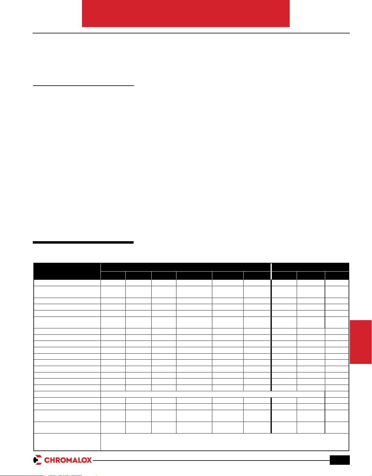
Heat Tracing Product Features
Industrial Commercial
Features
Max. Maintenance Temp. (°F) 150 225 302 320 302 900 100 50 225
Max. Exposure Temp. (°F)
Power Off
Max. W/Ft. 10 15 20 12 12 50 8 12 15
Max. Circuit Length (Ft.) 95-660 55-750 150-750 225-900 7,500 330-1,000 180-660 135-540 500-800
Buss Wire Size 16 16 16 12 16,14,12,10 N/A 16 16 16
Voltages
Hazardous Ratings Yes Ye s Yes Ye s Yes Yes No No No
Usable on Plastic Pipe Yes No No No No No Ye s Ye s Yes
Cut-to-Length in Field Ye s Yes Ye s Ye s Ye s No Ye s Ye s Ye s
Field Splicable Yes Yes Ye s Ye s Ye s No Ye s Ye s Ye s
Can be Overlapped Yes Ye s Ye s No No No Ye s Ye s Ye s
Output Varies with Temp. Ye s Ye s Yes No No No Yes Yes Ye s
Varies Output Along Length Yes Ye s Ye s No No No Ye s Ye s Ye s
Design of System Simple Simple Simple Simple Involved Involved Simple Simple Simple
Installation of System Easiest Easiest Easiest Simple Simple Involved Easiest Easiest Easiest
Fire Resistance Fair Fair Fair Fair Fair Excellent Fair Fair Fair
Chemical Resistance
Size (Max. In.) .435x.185 .435x 185 .435x.185 .435x.235 .435x.185 0.4 .435x.185 .435x.185 .435x.185
Accessories DL/EL/U D/UL DL/U DL/EL/U U DL/EL/U RG Access. DL/U
Monitor Wire Available
Applications
SRL SRP SRM/E CWM SLL Alloy 825 MI SRF SRF-RG HWM
185 275 420 400 450 1,100 185 185 275
120,
208-277
See Corrosion Guide, next page
Yes Ye s
FL,PL
FL = Freeze Protection
FH = Freeze Protection, High Exposure Temp.
PL = Process Maintenance, Low Temperature
120,
208-270
FL,FH,
PL,PH
120,
208-277
Contact
Factory
FL,FH,
PL,PH
120,
208-277, 480
Contact
Factory
FL,FH,
PL,PH
120-600 Up to 600
No No No No Yes
FL,FH,
PL,PH
PH = Process Maintenance, High Temperature
RG = Roof and Gutter De-icing
HWM = Hot Water Maintenance
FL,FH,
PL,PH
120,
208-277
FL RG HWM
120,
208-277
120,
208-270
PRODUCTS
HEAT TRACING
G-5
Page 2
Heating Cable
Heat Tracing Products
Application & Selection Guidelines (cont’d.)
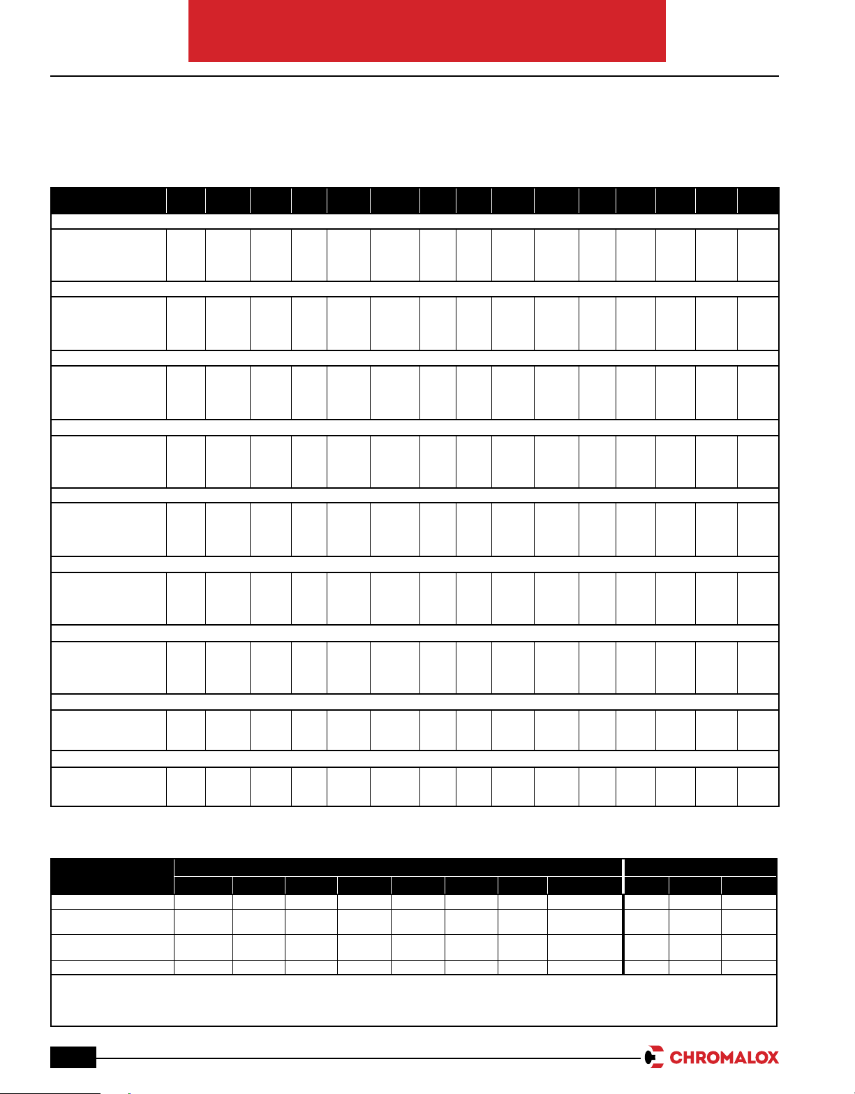
Agency Approvals
Area SRL-C SRL-CR SRL-CT HSRL SRM/E-C SRM/E-CT SRP HSRM CWM-C CWM-CT MI SRF-C SRF-CR SRF-RG HWM
Ordinary Area
UL
Factory Mutual
CSA
ATEX
Class 1 Div 2, Groups B,C,D
UL
Factory Mutual
CSA
ATEX
Class II Div 2, Groups F,G
UL
Factory Mutual
CSA
ATEX
Class III Div 2
UL
Factory Mutual
CSA
ATEX
Class 1 Div 1, Groups B,C,D*
UL
Factory Mutual
CSA
ATEX
Class II Div 1, Groups F,G
UL
Factory Mutual
CSA
ATEX
Class III Div 1
UL
Factory Mutual
CSA
ATEX
Zone 2 and Zone 22
Factory Mutual
CSA
ATEX
Zone 1 and Zone 21
Factory Mutual
CSA
ATEX
*ClassI,DivisionI,GroupsB,C&D-UL,CSA,FM-ContactyourLocalChromaloxSalesofcefordesignassistance.
✓
✓
✓
✓
✓
✓
✓
✓
✓
✓
✓
✓
✓
✓
✓
✓
✓
✓
✓
✓
✓
✓
✓
✓
✓
✓
✓
✓
✓
✓
✓
✓ ✓
✓
✓
✓
✓
✓
✓
✓
✓
✓
✓
✓
✓
✓
✓
✓
✓
✓
✓
✓
✓
✓
✓
✓
✓
✓
✓
✓
✓
✓
✓
✓
✓
✓
✓
✓
✓
✓
✓✓✓
✓ ✓
✓✓✓
✓✓✓
✓
✓
✓
✓
✓
✓
✓
✓
✓
✓
✓
✓
✓
✓
✓
✓
✓
✓
✓
✓
✓
✓
✓
✓
✓
✓
✓
✓
✓
✓
✓
✓
✓
✓
✓
✓
✓
✓
✓
✓
✓
✓
✓
✓
✓
✓
✓
✓
Corrosion Guide to Select Proper Cable Construction
Industrial Commercial
Exposure To
Moisture C, CR, CT C, CT C, CT CT CT C, CT CT Yes C, CR Yes C, CT
Aqueous Solutions of
Inorganic Compounds
Liquids Organic
Chemicals
Acids or Bases CT CT CT CT CT CT CT No No No CT
Note — This is a recommendation guide. Chromalox cannot warrant any Electric Heat Trace against failure by sheath degradation if such failure
is the result of operating conditions beyond the control of the heater manufacturer. It is the responsibility of the purchaser to make the
ultimate choice of sheath material based on knowledge of the chemical composition of the corrosive solution, character of materials
entering the solution, and controls which maintains the process.
G-6
SRL SRM/E SRP HSRL HSRM CWM SLL Alloy 825 MI SRF SRF-RG HWM
CR, CT CT CT CT CT CT CT No No No CT
CT CT CT CT CT CT CT Yes No No CT
Page 3

Heating Cable
Pipe Temperature (˚F)
Heat Output (W/Ft.)
0
4
12
16
20
24
8
30 50 70 90 110 130 150 170 190 210 230 250
20 W/Ft.
15 W/Ft.
10 W/Ft.
8 W/Ft.
5 W/Ft.
Cable Output vs.
Temperature
270 290
300
Heat Tracing Products
Application & Selection
Guidelines (cont’d.)
Required Jacket Material
Select the appropriate jacket configuration for
the desired level of mechanical and corrosive chemical protection. The CR over-jacket
option can be used when additional mechanical protection is desired. The CR over-jacket
option is required when the cable can be
exposed to aqueous inorganic chemicals. The
CT over-jacket option is required when the
cable can be exposed to organic chemicals or
strong corrosives. Use Corrosion Guide above
to determine the correct jacket material option
for the cable type selected.
Step 3 — Select Heating
Cable Wattage Rating
After calculating the heat loss
in the pipe and adjusting for any
application deviations, you may
determine which cable rating
to use. If you have selected a
self-regulating cable you must
adjust the output based on
maintenance temperatures,
using the Thermal Output
Rating Graphs shown on the individual product pages, select
the lowest cable rating that will
provide the pipe maintenance temperature. For Example: A
15 W/Ft. SRM/E cable @ 150°F
will output approximately
10 W/Ft. Multiple passes or runs
of cable may be required to
provide sufficient output per
foot calculated in Step 1. This is
accomplished with parallel runs
of cable or spiraling. Contact
your Local Chromalox Sales office.
Cable Output vs. Temperature
Step 4 — Determine Total Length of
Cable Required
The total amount of heating cable is
determined by adding the total footage of
pipe to be traced and adding for allowances
for the components such as flanges, valves,
pipe supports; then, multiply by the total
number of runs or Wrap Factor determined in
Step 3.
(Total Feet of Traced Pipe + Cable Allowance
for Components) x # of Runs = Total Cable
Length)
Step 5 — Determine Circuits &
Circuit Protection
Circuit protection depends on the breaker
size being used and the start-up temperature.
The National Electric Code (NEC 1996)
requires the use of ground fault protection
breakers for heating cable. Refer to the
specific data of the individual heat trace cable
to determine maximum circuit lengths. To
determine the number of circuits required for
each pipe, divide the total cable length found
in Step 4 by the maximum circuit length found
in the individual cable data charts. Round up
to the next higher number.
Number of Circuits = Cable Length
Maximum Circuit Length
Pipe Component Cable Allowance Estimation
Component Cable Allowance Factor (Ft.) x # Components Total Additional Cable
Flange Pair 1.5 x
Pipe Support 2.0 x
ButteryValve 2.5 x
Ball Valve 2.7 x
Globe Valve 4.0 x
Gate Valve 5.0 x
Example: Pipe: 150 feet
Valves: 1 globe valve
Pipe Supports: 2
Flanges: 2
Total Cable Length = [150 + (1 x 4) + (2 x 2) + (2 x 1.5)] x 2 runs
= 161 feet x 2 runs
= 322 feet
PRODUCTS
HEAT TRACING
G-7
Page 4

Heating Cable
Heat Tracing Products
Application & Selection Guidelines (cont’d.)
Design of Multiple Runs when Heat Requirements
Exceed Cable Output Ratings
Insulation
Sensors
Multiple Straight Runs
Heating Cable
Step 6 — Select Controls & General
Application Accessories
Chromalox provides a wide range of termination accessory and control options for your
heat tracing systems needs.
Accessory options range from ordinary area
under the insulation kits in our EL series all the
way through connections and terminations for
Division 1 hazardous areas in our HL series.
The accessories carry a full complement of
third party approvals from UL, Factory Mutual,
Canadian Standards, ATEX and IECex.
Controls range from Thermostats for both ambient air and pipe/tank sensing applications to
WeatherTrace power distribution and controls
panels through our IntelliTrace line of distribution, monitoring and control panels. Whether
your project is a few lines of freeze protection
or a few hundred lines of process piping we
have the right control option for your needs.
Spiral Run
Accessory Descriptions
U Series
• Designed for Ordinary and Hazardous Area
use in Industrial applications
• Integrated design allows for quick cable
termination
• Line carries worldwide approvals including
ATEX and IECex
• Reduced parts count results in fast installation times
• Line includes:
• Power Connection
• Multi Entry Connection (for splice, tee or
multiple power to 3 cables)
• Above Insulation End Seal
• Below Insulation End Seal
• Lighted End Seal
• Ambient Thermostat
• Line Sensing Thermostat
• Lighted End Seal
Thermostats also serve as power connection
for cable - eliminating need for extra power
connection box.
DL Series
• Designed for Ordinary and Hazardous Area
use in Industrial Applications
• Integrated design allows for fast installation
• Box design allows easy access for field wiring, maintenance and trouble shooting
• CSA, Factory Mutual and UL approved for
ordinary and Hazardous area use (Div. 2)
• Line Includes
• Power Connection
• Splice and Tee (connect up to 3 cables)
• Below Insulation End Seal
• Lighted End Seal (ordinary area use only)
• Ambient Thermostat
• Line Sensing Thermostat
• Thermostats also serve as power connection
for cable - eliminating need for extra power
connection box.
G-8
Page 5

Heating Cable
Heat Tracing Products
Application & Selection Guidelines (cont’d.)
EL Series
• Designed for use in ordinary areas for both
commercial and industrial applications
• Low profile designs allow for ease of insulation around connections
• Kits include standard electrical terminations
and heat shrink products familiar to most
installers
• Low parts count allows fast termination of
cables
• Third Party Approvals through UL, Factory
Mutual and CSA.
• Line Includes
• Junction Box
• Pipe Stand off with sealing grommets
and cable boots
• Heat shrink splice and tee kits
• Heat Shrink end caps
HL Series
• Specifically designed for use in Division 1
hazardous areas
• Corrosion Resistant housing made of high
strength cast aluminum
• Reduced parts count for fast installation
• Small profiles for ease of insulation
• Line Includes
• Power Connection
• Splice Kit
• Tee Kit
• End Seal Kit
• Add on Signal lights for End Seal and
Power Connection
Controls Descriptions
DL Controls
The DL Series temperature controls are available in four models to handle a broad range
of applications. Models include two ambient
sensing and two line sensing thermostats.
These high quality models combine On/Off
temperature control and cable power connection in one affordable, convenient easy to
install package. The line includes two 22 amp
capable models for Ordinary Area installations
and two 11 amp capable hermetically sealed
models for Division 2 hazardous area applications. Products carry UL, Factory Mutual and
CSA approvals.
EL Controls
The EL controls line contains ambient and
line sensing controllers for use in Division
1 and Division 2 areas. All products switch
22 amps and come in NEMA 4x and NEMA 7
rated enclosures. Two models are available in
dual output form. All capillaries are nontoxic
oil filled available in 8 and 10 foot lengths.
Products carry UL, Factory Mutual and CSA
approvals.
WeatherTrace Control and Distribution
Panels
The Chromalox FPAS, FPASM, FPLS, and
FPLSM series panels offer power distribution, ground fault protection, individual circuit
alarming, with options for both line sensing
and ambient sensing control. Line sensing is
accomplished in conjunction with U SERIES,
DL SERIES or EL SERIES thermostats. Ambient sensing can be accomplished with thermostats or optional Chromalox solid state 1604
series temperature controllers. The panels
are housed in NEMA 4 enclosures for indoor/
outdoor applications. NEMA 4X 304 stainless
steel enclosures may be selected as an option
for more harsh environments. The standard
models are available in 12,18,20,30 and 42
position panel boards with 100 and 225 amp
bus ratings in single and three phase configurations. Branch circuit breakers are available
in 20, 25, 30 and 40 amp single pole and two
pole configurations with 30mA ground-fault
equipment protection. Options for Z-purge
systems for hazardous area installation are
available. Sentinel monitoring system is available for alarm indication when a circuit loses
power. Common alarm available for interface
to building management systems. Panels are
built in a UL 508 certified manufacturing plant
and carry UL and cUL approvals.
DTS Digital Thermostat
The DTS-HAZ is a single circuit controller
which switches 30 Amps at 100-277 Vac
in Class I, Division 2 areas. It employs SSR
on/off control, soft start feature, programmable paramater values, AC or DC alarm and
large LED display. It comes complete with a
standard pipe stand or optional wall mount as
well as an RTD sensor. All of this is housed in
a 6" x 6" enclosure, wich facilitates all wiring
needs.
IntelliTRACE
The lTC is a 1 or 2 circuit microprocessorbased temperature controller, switching 40
Amps per circuit at 100-277 Vac, and may be
used in either freeze protection or process
temperature control applications. The ITC's
compact 10" x 8" x 6" NEMA 4X enclosure
facilitates all of the electrical connections and
it features a high resolution TFT display, PID
or On/Off SSR control, selectable soft start
program, dual RTD sensor input per circuit,
current load and GFEP monitoring. All process
variables may be monitored both locally and
remotely. The lTC is designed for line or ambient sensing heat trace applications in hazardous (Class I, Division 2) or non-hazardous
areas.
Should the lTC unit realize a failed sensor, the
controller automatically switches into a user
adjustable manual output duty cycle. This controller provides LED indication of load, power
and alarm status for each circuit, has front
panel capacitive touch user interface buttons
and comes complete with heavy gage stainless
steel mounting brackets.
IntelliTRACE Control, Monitoring and
Distribution Panels
The IntelliTRACE ITAS and ITLS Series is a
micro-processor based Control/Monitoring
and Power Management and Distribution system for Heat Trace Applications. The ITAS and
ITLS Series has models suitable for ordinary
as well as Class I, Division 2 areas and will
manage 6-72 circuits
The ITAS and ITLS Control Panel Series provides alarms for high / low temperatures, high/
low current, ground fault leakage and sensor
faults.
The 40 Amps per circuit capacity, the Integral
Circuit Panel and the Soft Start feature save
significant time, installation and maintenance
costs.
The customizable I/O (Sensor) Mapping, the
remote monitoring capability and the wireless
communication option provide desirable process management flexibility options.
®
ITC Series
SELF-REGULATING
G-9
 Loading...