

Page 1
Page 2
Insulation
Factor
Pipe Insulation TypePipe Insulation Type
Insulation
Factor
Glass fiber (ASTM C547) 1.00
Calcium silicate (ASTM C533) 1.48
Cellular glass (ASTM C552) 1.48
Rigid cellular urethane (ASTM C591) 0.64
Foamed elastomer (ASTM C534) 1.16
Mineral fiber blanket (ASTM C553) 1.16
Expanded perlite (ASTM C610) 1.90
A
Pipe Temperature (ºF)
Maintenance Temperature
0 10 20 30 50 60 70 80 90 100 110 120 130 140 150
Thermal Output (W/ft)
14
13
12
11
10
9
8
7
6
5
4
3
2
1
0
4.88
SRL10 & HSRL10
SRL8 & HSRL8
SRL5 & HSRL5
SRL3 & HSRL3
Cable Output
versus
Temperature
40
0 10 20 30 50 60 70 80 90 100 110 120 130 140 15040
Pipe Temperature (ºF)
SRL10 & HSRL10
Thermal Output (W/ft)
9
8
7
6
5
4
3
2
1
0
SRL8 &
HSRL8
SRL5 & HSRL5
SRL3 & HSRL3
Cable Output
versus
Temperature
Pipe Temperature (ºF)
Heat Output (W/ft)
21
20
19
18
17
16
15
14
13
12
11
10
9
8
7
6
5
4
3
2
1
0
15 W/ft
10 W/ft
5 W/ft
Cable Output
versus
Temperature
0 10 20 30 40 50 60 70 80 90 100 110 120 130 140 150 160 170 180 190 200 210 220 230
0 50 100 150 200 250 300
Pipe Temperature (ºF)
SRM/E20 &
HSRM20
Power Output (W/ft)
24
20
16
12
8
4
0
SRM/E15 &
HSRM15
SRM/E10 &
HSRM10
SRM/E8& HSRM8
SRM/E5& HSRM5
SRM/E3& HSRM3
Cable Output
versus
Temperature
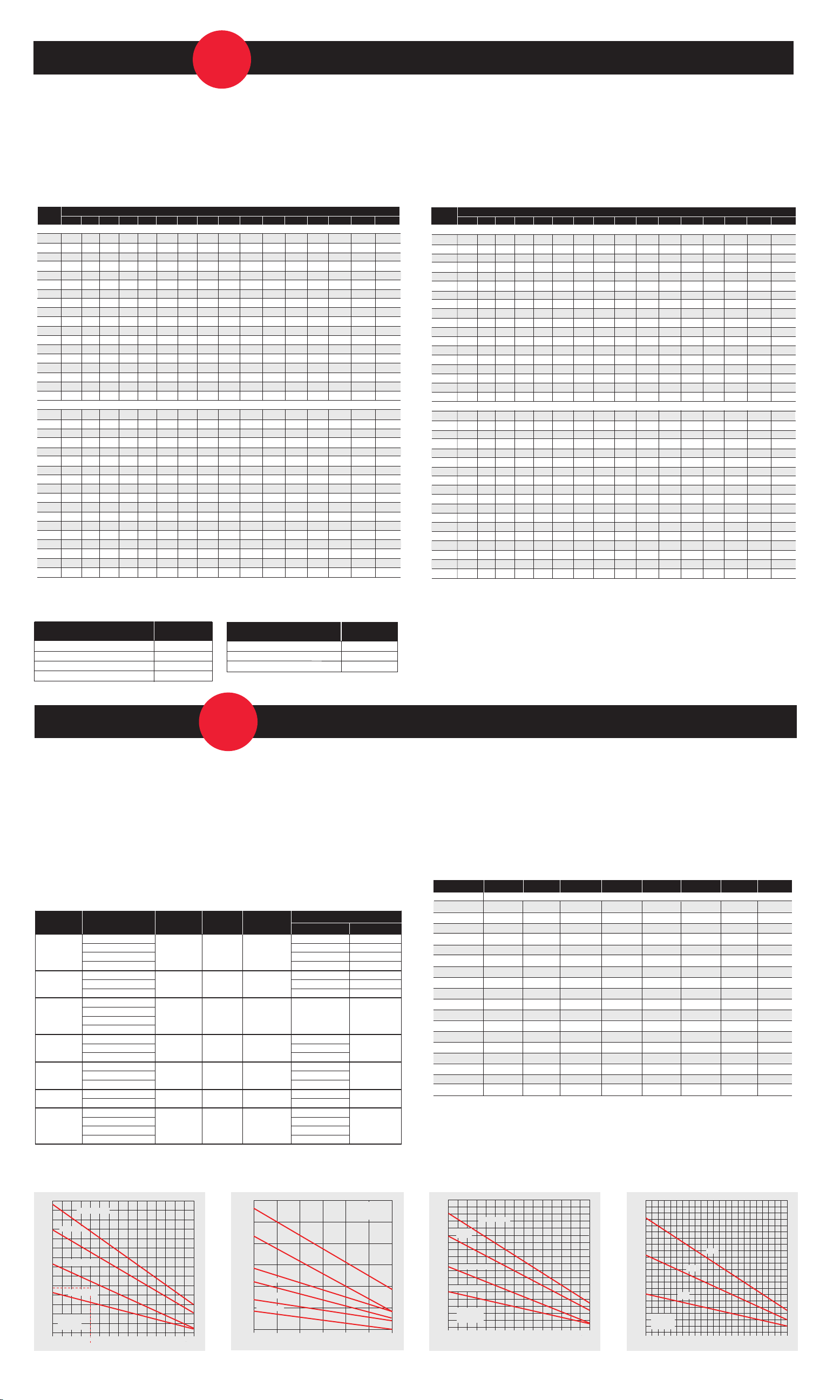
Pipe Heat Loss Calculations
1.Basic Heat Loss: After determining the difference between the ambient and desired pipe maintenance
temperature, T
, use Table 1 to figure the basic heat loss for the pipe size and insulation thickness.
m
2.Insulation Adjustment: Using Table 2, find the type of insulation being used and its insulation factor.
Table 1 Pipe Heat Loss Q
Nominal
Pipe Size,
in. (ID)
DegºF 40ºF 50ºF 60ºF 70ºF 80ºF 90ºF 100ºF 120ºF 140ºF 160ºF 180ºF 200ºF 220ºF 240ºF 260ºF
1
/2" W/ft 1.4 1.8 2.1 2.5 2.8 3.2 3.5 4.2 5.1 5.9 6.6 7.7 8.5 9.2 10.0
3
/4" W/ft 1.6 2.0 2.4 2.8 3.2 3.6 4.0 4.8 5.9 6.7 7.6 8.8 9.7 10.6 11.4
1" W/ft 1.8 2.3 2.8 3.2 3.7 4.1 4.6 5.5 6.8 7.7 8.7 10.1 11.1 12.1 13.2
11/2" W/ft 2.4 3.1 3.7 4.3 4.9 5.5 6.1 7.3 9.0 10.2 11.5 13.4 14.8 16.1 17.4
2" W/ft 2.8 3.5 4.1 4.8 5.5 6.2 6.9 8.3 10.1 11.6 13.0 15.2 16.7 18.2 19.7
21/2" W/ft 3.2 4.0 4.8 5.6 6.4 7.2 8.0 9.6 11.8 13.4 15.1 17.6 19.4 21.1 22.9
3" W/ft 3.7 4.7 5.6 6.5 7.4 8.4 9.3 11.2 13.7 15.6 17.6 20.5 22.5 24.6 26.6
4" W/ft 4.6 5.8 6.9 8.1 9.2 10.4 11.5 13.8 16.9 19.3 21.7 25.3 27.8 30.4 32.9
6" W/ft 6.4 8.0 9.6 11.2 12.8 14.4 16.0 19.2 23.5 26.9 30.2 35.2 38.7 42.2 45.8
8" W/ft 8.1 10.1 12.1 14.1 16.2 18.2 20.2 24.2 29.7 33.9 38.2 44.4 48.9 53.3 57.8
10" W/ft 9.9 12.4 14.8 17.3 19.8 22.2 24.7 29.6 36.3 41.5 46.7 54.3 59.8 65.2 70.6
12" W/ft 11.6 14.5 17.4 20.3 23.2 26.1 29.0 34.8 42.6 48.7 54.8 63.8 70.2 76.6 82.9
14" W/ft 12.6 15.8 19.0 22.1 25.3 28.4 31.6 37.9 46.5 53.1 59.7 69.5 76.5 83.4 90.4
16" W/ft 14.3 17.9 21.5 25.1 28.7 32.3 35.9 43.0 52.7 60.2 67.8 78.9 86.8 94.6 102.5
18" W/ft 16.0 20.1 24.1 28.1 32.1 36.1 40.1 48.1 58.9 67.4 75.8 88.2 97.0 105.9 114.7
20" W/ft 17.7 22.2 26.6 31.0 35.4 39.9 44.3 53.2 65.1 74.4 83.7 97.5 107.2 117.0 126.7
22" W/ft 19.4 24.3 29.1 34.0 38.8 43.7 48.5 58.2 71.3 81.5 91.7 106.7 117.4 128.0 138.7
24" W/ft 21.1 26.4 31.6 36.9 42.2 47.4 52.7 63.2 77.5 88.5 99.6 115.9 127.5 139.1 150.7
1
/2" W/ft 1.1 1.4 1.7 2.0 2.2 2.5 2.8 3.5 4.1 4.7 5.5 6.2 6.8 7.4 8.0
3
/4" W/ft 1.2 1.6 1.9 2.2 2.5 2.8 3.1 3.9 4.6 5.2 6.1 6.8 7.5 8.2 8.9
1" W/ft 1.4 1.8 2.2 2.5 2.9 3.2 3.6 4.5 5.3 6.0 7.1 7.9 8.7 9.5 10.3
11/2" W/ft 1.8 2.3 2.8 3.2 3.7 4.1 4.6 5.8 6.8 7.7 9.1 10.1 11.1 12.1 13.2
2" W/ft 2.1 2.6 3.1 3.6 4.2 4.7 5.2 6.6 7.6 8.7 10.3 11.4 12.6 13.7 14.9
21/2" W/ft 2.4 3.0 3.5 4.1 4.7 5.3 5.9 7.4 8.7 9.9 11.7 13.0 14.3 15.6 16.9
3" W/ft 2.7 3.4 4.1 4.8 5.4 6.1 6.8 8.6 10.0 11.4 13.5 15.0 16.5 18.0 19.4
4" W/ft 3.3 4.2 5.0 5.8 6.6 7.5 8.3 10.5 12.2 13.9 16.4 18.3 20.1 21.9 23.7
6" W/ft 4.5 5.7 6.8 7.9 9.0 10.2 11.3 14.2 16.6 19.0 22.4 24.9 27.3 29.8 32.3
8" W/ft 5.6 7.1 8.5 9.9 11.3 12.7 14.1 17.8 20.7 23.7 27.9 31.0 34.1 37.2 40.3
10" W/ft 6.8 8.0 10.3 12.0 13.7 15.4 17.1 21.5 25.1 28.7 33.9 37.6 41.4 45.1 48.9
12" W/ft 8.0 10.0 12.0 14.0 16.0 18.0 20.0 25.2 29.4 33.6 39.6 44.0 48.4 52.8 57.2
14" W/ft 8.7 10.9 13.0 15.2 17.4 19.5 21.7 27.3 31.9 36.5 43.0 47.7 52.5 57.3 62.1
16" W/ft 9.8 12.3 14.8 17.2 19.7 22.1 24.6 31.0 36.2 41.3 48.7 54.1 59.5 64.9 70.4
18" W/ft 11.0 13.7 16.4 19.2 21.9 24.7 27.4 34.5 40.3 46.0 54.3 60.3 66.3 72.3 78.4
20" W/ft 12.1 15.1 18.1 21.1 24.2 27.2 30.2 38.1 44.4 50.7 59.8 66.4 73.1 79.7 86.4
22" W/ft 13.2 16.5 19.8 23.1 26.4 29.7 33.0 41.6 48.5 55.4 65.3 72.6 79.9 87.1 94.4
24" W/ft 14.3 17.9 21.5 25.1 28.6 32.2 35.8 45.1 52.6 60.1 70.9 78.8 86.6 94.5 102.4
in W/ft Based on Temperature Differential and Insulation Thickness
P
Temperature DifferenceBetween Pipe and Ambient
1" Insulation Thickness
1.5" Insulation Thickness
3.Calculate Q
calculate the estimated heat loss, Q
4.Correct for Indoor Location/ Wind Speed: If location is indoors, multiply Q
: Multiply the basic heat loss figure from Table 1 by the adjustment factor from Table 2 to
F
, in watts per foot of pipe length.
F
by 0.9. Table 1 is based on
F
10% safety factor and 20 mph wind speed; add 5% margin for each 5 mph over 20 mph wind speed.
Nominal
Pipe Size,
in. (ID)
DegºF 40ºF 50ºF 60ºF 70ºF 80ºF 90ºF 100ºF 120ºF 140ºF 160ºF 180ºF 200ºF 220ºF 240ºF 260ºF
1
/2" W/ft 1.0 1.2 1.4 1.7 1.9 2.2 2.4 3.0 3.5 4.0 4.8 5.3 5.8 6.3 7.2
3
/4" W/ft 1.1 1.4 1.6 1.9 2.2 2.4 2.7 3.4 4.0 4.5 5.3 5.9 6.5 7.1 8.1
1" W/ft 1.2 1.5 1.8 2.1 2.4 2.7 3.0 3.8 4.4 5.0 5.9 6.6 7.3 7.9 9.0
11/2" W/ft 1.5 1.9 2.3 2.7 3.0 3.4 3.8 4.8 5.6 6.4 7.5 8.4 9.2 10.0 11.4
2" W/ft 1.7 2.2 2.6 3.0 3.4 3.9 4.3 5.4 6.3 7.2 8.5 9.5 10.4 11.4 12.9
21/2" W/ft 1.9 2.4 2.9 3.4 3.8 4.3 4.8 6.0 7.1 8.1 9.5 10.6 11.6 12.7 14.4
3" W/ft 2.2 2.8 3.3 3.9 4.4 5.0 5.5 6.9 8.1 9.2 10.9 12.1 13.3 14.5 16.4
4" W/ft 2.6 3.3 4.0 4.6 5.3 5.9 6.6 8.3 9.7 11.1 13.1 14.5 16.0 17.4 19.7
6" W/ft 3.6 4.5 5.3 6.2 7.1 8.0 8.9 11.2 13.1 15.0 17.6 19.6 21.5 23.5 26.6
8" W/ft 4.4 5.6 6.7 7.8 8.9 10.0 11.1 14.0 16.3 18.6 22.0 24.4 26.9 29.3 33.2
10" W/ft 5.3 6.7 8.0 9.3 10.6 12.0 13.3 16.8 19.6 22.3 26.3 29.3 32.2 35.1 39.8
12" W/ft 6.2 7.8 9.3 10.9 12.4 14.0 15.5 19.5 22.8 26.0 30.7 34.1 37.5 40.9 46.3
14" W/ft 6.7 8.4 10.1 11.8 13.4 15.1 16.8 21.2 24.7 28.2 33.3 37.0 40.7 44.4 50.2
16" W/ft 7.6 9.5 11.3 13.2 15.1 17.0 18.9 23.8 27.8 31.8 37.4 41.6 45.7 49.9 56.5
18" W/ft 8.4 10.5 12.6 14.7 16.8 18.9 21.0 26.5 30.9 35.3 41.6 46.2 50.8 55.4 62.8
20" W/ft 9.2 11.6 13.9 16.2 18.5 20.8 23.1 29.1 34.0 38.8 45.7 50.8 55.9 61.0 69.1
22" W/ft 10.1 12.6 15.2 17.7 20.2 22.7 25.3 31.8 37.1 42.4 50.0 55.6 61.1 66.7 75.5
24" W/ft 11.0 13.7 16.4 19.2 21.9 24.7 27.4 34.5 40.3 46.0 54.3 60.3 66.3 72.3 81.9
609.6 mm W/m 36.1 44.9 53.8 63.0 71.9
1
/2" W/ft 0.8 1.0 1.2 1.4 1.6 1.8 2.0 2.5 2.9 3.4 4.0 4.4 4.8 5.5 6.0
3
/4" W/ft 0.9 1.1 1.3 1.5 1.8 2.0 2.2 2.8 3.2 3.7 4.4 4.8 5.3 6.1 6.67
1" W/ft 1.0 1.3 1.5 1.8 2.0 2.3 2.5 3.2 3.7 4.2 5.0 5.5 6.1 6.9 7.5
11/2" W/ft 1.2 1.5 1.8 2.1 2.4 2.7 3.0 3.8 4.4 5.0 5.9 6.6 7.3 8.3 9.0
2" W/ft 1.3 1.7 2.0 2.3 2.6 3.0 3.3 4.2 4.9 5.5 6.5 7.3 8.0 9.1 9.9
21/2" W/ft 1.5 1.9 2.2 2.6 3.0 3.3 3.7 4.7 5.4 6.2 7.3 8.1 9.0 10.2 11.1
3" W/ft 1.7 2.1 2.5 2.9 3.4 3.8 4.2 5.3 6.2 7.1 8.3 9.2 10.2 11.6 12.6
4" W/ft 2.0 2.5 3.0 3.5 4.0 4.5 5.0 6.3 7.4 8.4 9.9 11.0 12.1 13.8 15.0
6" W/ft 2.6 3.3 3.9 4.6 5.2 5.9 6.5 8.2 9.6 10.9 12.9 14.3 15.7 17.9 19.4
8" W/ft 3.2 4.0 4.8 5.6 6.4 7.2 8.0 10.1 11.8 13.4 15.8 17.6 19.4 22.1 23.9
10" W/ft 3.8 4.8 5.7 6.7 7.6 8.6 9.5 12.0 14.0 16.0 18.8 20.9 23.0 26.2 28.4
12" W/ft 4.4 5.5 6.5 7.6 8.7 9.8 10.9 13.7 16.0 18.3 21.6 24.0 26.4 30.1 32.6
14" W/ft 4.7 5.9 7.1 8.3 9.4 10.6 11.8 14.9 17.3 19.8 23.4 26.0 28.6 32.6 35.3
16" W/ft 5.3 6.7 8.0 9.3 10.6 12.0 13.3 16.8 19.6 22.3 26.3 29.3 32.2 36.7 39.8
18” W/ft 5.9 7.4 8.8 10.3 11.8 13.2 14.7 18.5 21.6 24.7 29.1 32.3 35.6 40.6 44.0
20" W/ft 6.4 8.1 9.7 11.3 12.9 14.5 16.1 20.3 23.7 27.0 31.9 35.4 39.0 44.4 48.1
22" W/ft 7.0 8.8 10.5 12.3 14.0 15.8 17.5 22.1 25.7 29.4 34.7 38.5 42.4 48.3 52.3
24" W/ft 7.6 9.5 11.3 13.2 15.1 17.0 18.9 23.8 27.8 31.8 37.4 41.6 45.7 52.2 56.5
Temperature Difference Between Pipe and Ambient
2" Insulation Thickness
3" (76.2 mm) Insulation Thickness
3” Insulation Thickness
Table 2
Insulation Adjustment Factors
B
Chromalox Cable Selection
1.Select Heating Cable Family: Based on the maximum maintenance temperature rating, maximum
exposure temperature rating, and area classification, select the heating cable family from Table 3. (See
Chromalox Heat Trace Cable Product Information Sheets for cable construction options, voltage ratings,
and wattage outputs available.)
2.Select Thermal Output Rating:
(a) For Metal Pipes – Use Figures 1, 2 or 4
(b) For Plastic Pipes – Use Figure 3 by finding the intersection of the calculated heat loss, Q
maintenance temperature, Tm. Select the cable with a thermal output that equals or exceeds QFat Tm.
Table 3
Heating Cable
Family
SRL
(Self-Regulating
Low Temperature)
SRM/E
(Self-Regulating
Medium
Temperature)
SRP
(Self-Regulating
Medium
Temperature)
HSRL
(H-Self-Regulating
Low Temperature)
HSRM
(H-Self-Regulating
Medium
Temperature)
CWM
(ConstantWattage)
MI (Mineral
Insulated)
NOTE: It is the responsibility of the facility manager or engineer to determine the classification of an area where heat trace will be installed. The factory can help determine a suitable
cable based on the information provided.
Figure 1
Heating Cable Families
Area
Classification
Ordinary
Class I, Div.2, Gr. B, C, D CSA, FM, (Gr.A, CSA Only) GOST, Cenelec,CE, ATEX
Class II, Div.2, Gr. E, F,G CSA, FM, (Gr. E, CSA Only) GOST, Cenelec,CE
Class III, Div.2 FM Only GOST,Cenelec,CE, ATEX
Ordinary
Class I Div.2, Gr. A, B, C, D CSA, FM, (Gr.A, CSA Only) GOST, Cenelec,CE, ATEX
Class II, Div.2, Gr. F, G CSA Only GOST,Cenelec,CE, ATEX
Ordinary
Class I, Div.2, Gr. B, C, D
Class II, Div.2, Gr. F, G
Class III
Class I, Div.1, Gr. B, C, D
Class II, Div.1, Gr. E, F,G CSA, FM
Class III, Div.1 CSA, FM
Class I, Div.1, Gr. B, C, D
Class II, Div.1, Gr. E, F,G CSA, FM
Class III, Div.1 CSA, FM
Ordinary
HazardousArea, Consult Factory
Ordinary
Class I, Div.2, Gr. B, C, D CSA, FM
Class II, Div.2, Gr. E, F,G CSA, FM
Class III CSA, FM
Pipe
Material
Plastic/Metal 150ºF / 65ºC 185ºF / 85ºC
Metal Only 302ºF / 150ºC 420ºF / 215ºC
Metal Only 225ºF / 110ºC 275ºF / 135ºC
Plastic/Metal 150ºF / 65ºC 185ºF / 85ºC
Metal Only 302ºF / 150ºC 420ºF / 215ºC
Metal Only Consult Factory 392ºF / 200ºC
Metal Only Consult Factory 1,100ºF / 595ºC
Maximum
Maintenance
Temperature
SRL & HSRL – Thermal Output
Ratings on Insulated Metal Pipe
Maximum Exposure
Temperature
(Power Off)
Figure 2
U.S. Other
UL, CSA, FM GOST, Cenelec,CE, ATEX
UL, CSA, FM GOST, Cenelec,CE, ATEX
UL, CSA, FM
Pending
CSA, FM
CSA, FM
UL, CSA
CSA, FM
SRM/E & HSRM – Thermal Output
Ratings on Insulated Metal Pipe
, and pipe
F
Approvals
GOST,Cenelec,CE, ATEX
Pending
3.Determine Total Cable Length: In addition to pipe length, in-line components such as valves, flanges,
and pipe supports require additional heat tracing to maintain T
cable length required by combining the pipe length with the additional lengths needed for all the
other components.
Additional Cable Lengths Required for In-Line Components
Globe Valve
on Pipe Size)
Ball Valve
Butterfly Valve
ft
Table 4
Piping Size
1
in. 1.00 1.00 1.00 1.00 1.00 1.00 1.00 0.30
2
/
3
in. 1.50 1.00 1.00 1.00 1.50 1.00 1.00 0.30
4
/
1 in. 2.00 1.00 1.00 1.00 1.50 1.00 1.00 0.30
1
1
in. 2.50 1.50 1.50 1.50 2.00 2.00 2.00 0.30
2
/
2 in. 2.50 2.00 2.00 2.00 2.00 2.00 2.00 0.30
1
2
in. 2.50 2.00 2.00 2.00 2.00 2.00 2.00 0.30
2
/
3 in. 3.00 2.50 2.50 2.50 2.00 2.00 2.00 0.50
4 in. 4.00 3.00 3.00 3.00 2.50 2.50 2.50 0.50
6 in. 5.00 3.50 3.50 3.50 2.50 2.50 2.50 0.80
8 in. 7.00 4.00 4.00 4.00 2.50 2.50 2.50 0.80
10 in. 8.00 4.50 4.50 4.50 3.00 3.00 3.00 0.80
12 in. 9.00 5.00 5.00 5.00 3.00 3.00 3.00 0.80
14 in. 10.00 5.50 5.50 5.50 3.00 3.00 3.00 1.00
16 in. 11.00 6.00 6.00 6.00 3.50 3.50 3.50 1.00
18 in. 12.00 7.00 7.00 7.00 3.50 3.50 3.50 1.00
20 in. 13.00 7.50 7.50 7.50 3.50 3.50 3.50 1.00
22 in. 13.00 7.50 7.50 7.50 3.50 3.50 3.50 1.00
24 in. 15.00 8.00 8.00 8.00 4.00 4.00 4.00 1.00
Figure 3
Based on Pipe IPS (Ir
Gate Valve
SRL & HSRL – Thermal Output Ratings
on Plastic Pipe with Aluminum Tape
. See Table 4. Calculate the total
m
Shoe Support
Figure 4
Hanger Support
SRP – Thermal Output Ratings
on Insulated Metal Pipe
Sleeper Support
Flange Pair
Page 3

Metallic Pipe
Fiberglass Tape
FT-3
Self Regulating
Heating Cable
• Low Temperature
SRL, HSRL, SRF
• Medium Temperature
SRM/E, SRP, HSRM
Self Regulating
Heating Cable
• Low Temperature
SRL, HSRL, SRF
• Medium Temperature
SRM/E, SRP, HSRM
Fiberglass Tape
FT-3
For multiple heaters place
control sensor 90˚ from nearest
heater or centered between
equally spaced heaters.
Control
Sensor
45˚
Thermal
Insulation
Top
Weatherproof
Jacket
Cable located at nominal
45˚ below horizontal
centerline.
Cable located at nominal
45˚ below horizontal
centerline on either side.
45˚
Top
90˚
Top
45˚
Heating Cable/Sensor Location
Self Regulating
Heating Cable
• Low Temperature
SRL, HSRL, SRF
• Medium Temperature
SRM/E, SRP, HSRM
Pipe Support
3 in. / 75 mm Typical
Metal Pipe
Support Shoe
Fiberglass Tape
FT-3
Step 1
Step 2
Self Regulating Heating Cable
• Low Temperature SRL, HSRL, SRF
• Medium Temperature SRM/E, SRP, HSRM
Metallic Pipe
Weatherproof Jacket
Thermal Insulation
Fiberglass Tape
FT-3
Self Regulating
Heating Cable
• Low Temperature
SRL, HSRL, SRF
• Medium Temperature
SRM/E, SRP, HSRM
Step 1
Start tracing at the end of the pipe and work your way back to spool.
Step 3
Metal Pipe
Spool
Metal Pipe
Self Regulating Heating Cable
• Low Temperature
SRL, HSRL, SRF
• Medium Temperature
SRM/E, SRP, HSRM
Fiberglass Tape
FT-3
Fiberglass Tape
FT-3
Step 2
Leave a loop of cable at heat sinks such as
valves, pipe supports and flange sets. use
FT-3 fiberglass tape to secure cable to pipe
at 18 in. / 455 mm intervals.
Plastic
Pipe
Self Regulating
Heating Cable
• Use Low Temperature
SRL, HSRL, SRF Cable
Aluminum Tape
AL-1
Plastic Pipe Installation
Note: Aluminum tape must be used under or
over heating cable to spread heat transfer.
Fiberglass Tape
FT-3
Fiberglass Tape
FT-3
Heating Cable
Insulation
Pipe Strap
Caution
Labels
Ask about Chromalox Class 1 Div.1
Cables & Accessories as well as a full
line of High-Temperature Cables.
Copyright © 2002-2005, 2009-2012, Chromalox, Inc. All rights reserved.
Electric Heat Trace
Quick Install
Guide
Quick Install Guide is a specification
tool only. Always refer to proper
installation instructions when
installing heat trace cable.
CONTROL SYSTEMS
DTS-HAZ
Digital ThermoStat / Power Connection
Line- or Ambient-Sensing
UAS
Ambient-Sensing
UBC
Line-Sensing
• 0˚-225˚F / 0˚-107˚C
temperature rating
• 120-480 VAC, 22A
switching capability
• Freeze protection
applications
• 0˚-400˚F / 0˚-205˚C
set points
• 120-480 VAC, 22A
switching capability
• Freeze protection
applications
• Ordinary or hazardous areas
(Class 1, Division 2)
• -45˚-485˚F/-43˚-252˚C programmable
• 100-277 VAC, 30A SSR, soft start,
large LED display
• Freeze protection & process temperature
maintenance applications
Combination Single Point Temperature Controls &
Power Connection Boxes
• 1 to 4, 6 to 72 loops
• Fully wired. GFI, current, temperature,
and sensor alarm/monitoring
• Owner sensor mapping, soft start,
user-friendly touchscreen HMI
• Up to 40 loops
• Pre-wired and assembled
monitoring and distribution (saves
time on installation)
• Includes the Sentinel monitoring
system
Installation Tips
• Temporarily position cable on
pipe and equipment to ensure
proper distribution.
• Leave a loop of cable at heat
sinks such as valves, pipe
supports and flange sets. Use
FT-3 fiberglass tape to secure
cable to pipe at 18 in. / 455 mm
(nom) intervals using recommended method.
• Always observe minimum
bend radius.
Power Connection Box
(UPC)
Above Insulation
Cable End Seal
(UES)
Below Insulation
Cable End Seal
(RTES)
Multiple Entry
Connection
(UMC)
and sensor alarm/monitoring
t
s
Now suitable for
Class1,Division2areas!
 Loading...