

Page 1
Installation & Operation Manual
3400 1/32 DIN
Automatic Tuning Smarter
Logic Temperature Controller
PK545
0037-75576
April 2018
i
Page 2

Safety and Warranty Information
Warning Symbol
This Symbol calls attention to an operating procedure
or practice which if not correctly performed or adhered
to, could result in severe personal injury or damage to
the product or system.
Do not proceed beyond a warning symbol until the indicated conditions are fully understood and met.
FM approved high limit controllers should always be
used in heated systems.
Manual Use
Installers ................................................... Chapter 1, 2
Basic Function User ............................. Chapter 1, 3, 5
Enhanced Function User .................. Chapter 1, 3, 4, 5
System Designer .......................................All Chapters
Expert User ......................................................Page 11
Warranty and Returns Statement
These products are sold by Chromalox under the warranties set forth in the following paragraphs. Such warranties are extended only with respect to a purchase
of these products, as new merchandise, directly from
Chromalox or from a Chromalox distributor, representative or reseller and are extended only to the first
buyer thereof who purchases them other than for the
purpose of resale.
Warranty
These products are warranted to be free from functional defects in material and workmanship at the time the
products leave Chromalox factory and to conform at
that time to the specifications set forth in the relevant C
instruction manuals sheet or sheets, for such products
for a period of three years.
THERE ARE NO EXPRESSED OR IMPLIED WARRANTIES, WHICH EXTEND BEYOND THE WARRANTIES HEREIN AND ABOVE SET FORTH.
CHROMALOX MAKES NO WARRANTY OF MERCHANTABILITY OR FITNESS FOR A PARTICULAR
PURPOSE WITH RESPECT TO THE PRODUCTS.
Limitations
Chromalox shall not be liable for any incidental damages, consequential damages, special damages, or any
other damages, costs or expenses excepting only the
cost or expense of repair or replacement as described
above. Products must be installed and maintained in
accordance with Chromalox instructions. There is no
warranty against damage to the product resulting from
corrosion. Users are responsible for the suitability of
the products to their application.
For a valid warranty claim, the product must be returned carriage paid to the supplier within the warranty period. The product must be properly packaged
to avoid damage from electrostatic discharge or other
forms of harm during transit.
ii
Page 3

Table of Contents
Contents Page Number
Safety & Warranty ................................................................................................................................................... ii
Chapter 1 Overview ................................................................................................................................................ 1
1-1 Features ....................................................................................................................................................... 1
1-2 Ordering Code ............................................................................................................................................. 3
1-3 ProgrammingPort andDIP Switch ............................................................................................................... 4
1-4 Keys and Displays ....................................................................................................................................... 5
1-5 Menu Overview ............................................................................................................................................ 7
1-6 System Modes ............................................................................................................................................. 8
1-7 Parameter Descriptions ............................................................................................................................... 9
Chapter 2 Installation ........................................................................................................................................... 17
2-1 Unpacking ................................................................................................................................................. 17
2-2 Mounting ................................................................................................................................................... 17
2-3 Wiring Precautions .................................................................................................................................... 18
2-4 Power Wiring ............................................................................................................................................. 18
2-5 Sensor Installation Guidelines ................................................................................................................... 19
2-6 Thermocouple Input Wiring ....................................................................................................................... 19
2-7 RTD Input Wiring ....................................................................................................................................... 20
2-8 Linear DC Input Wiring .............................................................................................................................. 20
2-9 CT / Heater Current Input Wiring ............................................................................................................... 21
2-10 Event Input wiring .................................................................................................................................... 22
2-11 Output 1 Wiring ....................................................................................................................................... 22
2-12 Output 2 Wiring ....................................................................................................................................... 24
2-13 Alarm 1 Wiring ......................................................................................................................................... 25
2-14 Alarm 2 Wiring ......................................................................................................................................... 26
2-15 RS-485 .................................................................................................................................................... 27
2-16 RS-232 .................................................................................................................................................... 28
2-17 Analog Retransmission ............................................................................................................................ 29
2-18 Programming Port ................................................................................................................................... 30
Chapter 3 Programming the Basic Function ..................................................................................................... 31
3-1 Input 1 ....................................................................................................................................................... 32
3-2 OUT1 & OUT2 Types ................................................................................................................................. 33
3-3 Rearrange User Menu ............................................................................................................................... 33
3-4 Display SV Instead of PV ........................................................................................................................... 34
3-5 Heat Only Control ...................................................................................................................................... 34
3-6 Cool Only Control ...................................................................................................................................... 35
3-7 Heat - Cool Control ................................................................................................................................... 36
3-8 Dwell Timer ................................................................................................................................................ 37
3-9 Process Alarms .......................................................................................................................................... 38
3-10 Deviation Alarms ...................................................................................................................................... 40
3-11 Deviation Band Alarms ............................................................................................................................ 41
3-12 Heater Break Alarm ................................................................................................................................. 42
3-13 Loop Break Alarm .................................................................................................................................... 43
3-14 Sensor Break Alarm ................................................................................................................................. 44
3-15 SP1 Range ............................................................................................................................................... 44
3-16 PV1 Shift .................................................................................................................................................. 45
3-17 Failure Transfer ........................................................................................................................................ 46
3-18 Bumpless Transfer ................................................................................................................................... 47
3-19 Self-tuning ............................................................................................................................................... 48
3-20 Auto-tuning .............................................................................................................................................. 49
3-21 Manual Tuning ......................................................................................................................................... 51
3-22 Signal Conditioner DC Power Supply ..................................................................................................... 54
3-23 Manual Control ........................................................................................................................................ 55
iii
Page 4

Contents Page Number
3-24 Display Mode ........................................................................................................................................... 55
3-25 Heater Current Monitoring ....................................................................................................................... 56
3-26 Reload Default Values .............................................................................................................................56
Chapter 4 Programming the Full Function ......................................................................................................... 57
4-1 Event Input ................................................................................................................................................ 57
4-2 Second Set Point ....................................................................................................................................... 58
4-3 Second PID Set ......................................................................................................................................... 58
4-4 Ramp & Dwell ............................................................................................................................................ 59
4-5 Remote Set Point ...................................................................................................................................... 60
4-6 Differential Control ..................................................................................................................................... 61
4-7 Output Power Limits .................................................................................................................................. 62
4-8 Data Communication ................................................................................................................................. 63
4-9 Analog Retransmission .............................................................................................................................. 64
4-10 Digital Filter .............................................................................................................................................. 65
4-11 Sleep Mode ............................................................................................................................................. 65
4-12 Pump Control .......................................................................................................................................... 66
4-13 Remote Lockout ...................................................................................................................................... 67
Chapter 5 Applications ........................................................................................................................................ 68
5-1 Pump / Pressure Control ........................................................................................................................... 68
5-2 Variable Period Full Wave SSR ( VPFW SSR ) ........................................................................................... 69
5-3 Heat Only Control ...................................................................................................................................... 71
5-4 Cool Only Control ...................................................................................................................................... 72
5-5 Heat - Cool Control ................................................................................................................................... 73
5-6 Ramp & Dwell ............................................................................................................................................ 74
5-7 Remote Set Point ...................................................................................................................................... 77
5-8 Differential Control ..................................................................................................................................... 78
5-9 Dual Set Point / PID ................................................................................................................................... 79
5-10 RS-485 .................................................................................................................................................... 81
5-11 RS-232 .................................................................................................................................................... 82
5-12 Retransmit ............................................................................................................................................... 82
Chapter 6 Calibration ........................................................................................................................................... 84
Chapter 7 Error Codes & Troubleshooting ......................................................................................................... 87
Chapter 8 Specifications ..................................................................................................................................... 90
Appendix ............................................................................................................................................................... 94
A-1 Menu Existence Conditions ...................................................................................................................... 94
A-2 Factory Menu Description ......................................................................................................................... 96
A-3 Glossary .................................................................................................................................................... 98
A-4 Memo ...................................................................................................................................................... 104
iv
Page 5

Chapter 1
1-1 Features (**Unique, *Valuable)
**High accuracy 18-bit input A D
**High accuracy 15-bit output D A
**Fast input sample rate (5 times / second)
**Two function complexity levels
**User menu configurable
**Adaptive heat-cool dead band
**Pump control
*Fuzzy + PID microprocessor-based control
*Automatic programming
*Differential control
*Auto-tune function
*Self-tune function
*Sleep mode function
*“Soft-start” ramp and dwell timer
*Programmable inputs (thermocouple, RTD, mA, VDC)
ETR-3400 Fuzzy Logic plus PID microprocessor-based controller, incorporates a bright, easy to read 4-digit LED
display, indicating the process or set value. FUZZY LOGIC technology enables a process to reach a predetermined set point in the shortest time, with the minimum of overshoot during power-up or external load disturbance.
The units are housed in a 1/32 DIN case, measuring 24 mm x 48 mm with 98 mm behind panel depth. The units
feature three touch keys to select the various control and input parameters. Using a unique function, you can put
at most 5 parameters in front of the user menu by using SEL1 to SEL5 contained in the setup menu. This is particularly useful for quick access to commonly used settings.
ETR-3400 is powered by 11-26 V DC / AC or 90 - 264 V AC supply, incorporating a 3 amp. control relay output, 5V
logic alarm output and a 3 amp. alarm relay output. The second alarm can be configured into second output for
cooling purposes or a dwell timer. Alternative output options include SSR drive, triac, 4 - 20 mA and 0 - 10 volts.
ETR- 3400 is fully programmable for PT100, thermocouple types J, K, T, E, B, R, S, N, L, 0 - 20 mA, 4 -20 mA and
voltage signal input, with no need to modify the unit. The input signals are digitized by using a 18-bit A to D converter. Its fast sampling rate allows the ETR-3400 to control fast processes such as pressure and flow. The selftune feature can be used to optimize the control parameters as soon as undesired control result is observed. Unlike auto-tuning, Self-tune will produce less disturbance to the process Digital communications, RS-485, RS-232
or 4 - 20 mA retransmission are available as an additional option. These options allow ETR-3400 to be integrated
with supervisory Three different methods can be used to program the ETR-3400. 1) Use the keys on the front panel
to program the unit manually, 2) Use a PC and setup software to program the unit via RS-485 or RS-232 COMM
port. 3) Use P10A, a hand-held programmer specifically designed for the ETR series controllers.
Although PID control has been used and proved to be an efficient controlling method by many industries, PID tuning is difficult to deal wit, some sophisticated systems such as second and higher order systems, long time-lag
systems, during set point change and/or load disturbance. The PID principle is based on a mathematic modeling
which is obtained by tuning the process. Unfortunately, many systems are too complex to describe in numerical
terms precisely. In addition, these systems may vary from time to time. In order to overcome the imperfections of
PID control, Smarter Logic Technology is introduced. Smarter Logic is a linguistic control which controls the system by experience and does not need to simulate the system precisely as PID. Smarter Logic is the OGDEN trade
mark for Fuzzy Logic . An ETR with Smarter Logic continues decision making and will prevent initial overshoot and
set point differentials due to process disturbances. Control results are virtually perfect. Not only is control performance improved, software and design innovations have made available other improvements over conventional
controllers.
*Analog input for remote set point and CT
*Event input for changing function & set point
*Programmable digital filter
*Hardware lockout + remote lockout protection
*Loop break alarm
*Heater break alarm
*Sensor break alarm + Bumpless transfer
*RS-485, RS-232 communication
*Analog retransmission
*Signal conditioner DC power supply
*A wide variety of output modules available
*Safety UL / CSA / IEC1010 1
*EMC / CE EN61326
*Front panel sealed to NEMA 4X & IP65
11
Page 6
information
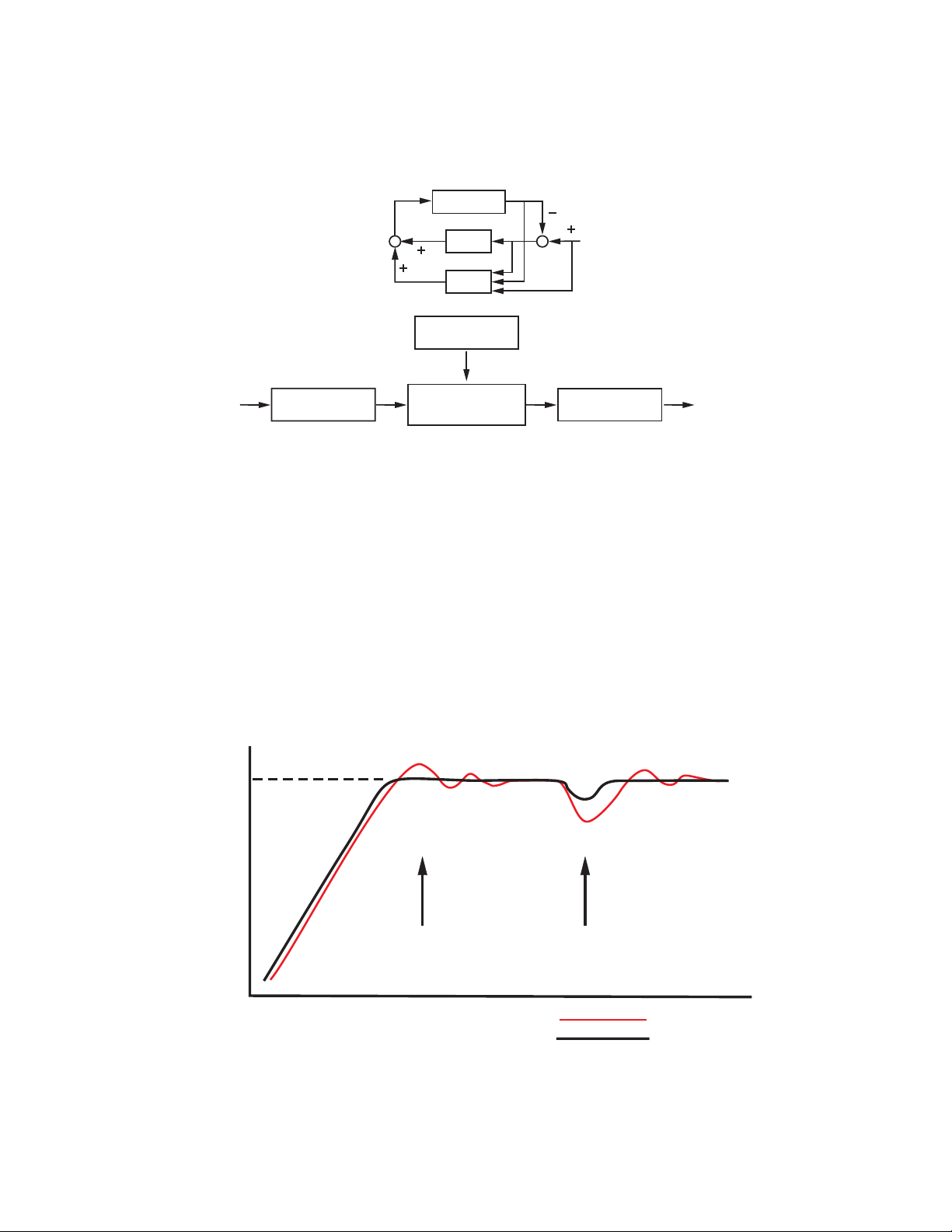
Figure 1.1 Fuzzy PID System Block
PID + FUZZY CONTROL
Set
MV PV
PROCESS
PID
+
+
Digital
information
FUZZY
Fuzzy Rule
Language
information
Fuzzy Inference
Engine
The function of Fuzzy Logic is to adjust PID parameters internally in order to make
PID + FUZZY CONTROL
Smarter Logic causes the following:
If temperature difference is large and temperature rate is large, then delta MV is large.
If temperature difference is large and temperature rate is small, then delta MV is small.
_
+
SV
DefuzzifierFuzzifier
Digital
Figure 1.2 Fuzzy PID Enhances Control Stability
Temperature
point
Warm Up
PID tuned controller
PID+Fuzzy control
Load Disturbance
Time
2
Page 7
1-2 Ordering Code
A
CT94-1 = 0 - 50 Amp. AC Current T
OM95-3 = Isolated 4 - 20 mA / 0 - 20 mA Analog Output Module
OM95-4 = Isolated 1 - 5V / 0 - 5V Analog Output Module
OM95-5 = Isolated 0 - 10V Analog Output Module
OM94-6 = Isolated 1A / 240V
DC94-1 = Isolated 20V / 25mA DC Output P
DC94-2 = Isolated 12V / 40mA DC Output P
DC94-3 = Isolated 5V / 80mA DC Output P
CM94-1 = Isolated RS
CM94-2 = Isolated RS
CM94-3 = Isolated 4 - 20 mA / 0 - 20 mA R
CM94-4 = Isolated 1 - 5V / 0 - 5V R
CM94-5 = Isolated 0 - 10V R
CC94-1 = RS
UM34001A = ETR-3400 User's Manual
Standard Model:
ETR
Standard Model:
ETR
-Net
-Net
ETR-3400
1 2
4: 90 - 264 VAC, 50/60 HZ
4: 90 - 264 VAC, 50/60 HZ
5: 11 - 26 VAC or VDC
5: 11 - 26 VAC or VDC
1: Standard Input
1: Standard Input
Input 1 - Universal Input
Input 1 - Universal Input
Thermocouple: J, K, T, E, B,
Thermocouple: J, K, T, E, B,
R, S, N, L
R, S, N, L
RTD: PT100 DIN, PT100 JIS
RTD: PT100 DIN, PT100 JIS
Current: 4 - 20mA, 0 - 20 mA.
Current: 4 - 20mA, 0 - 20 mA.
Voltage: 0 - 1V, 0 - 5V, 1 - 5V,
Voltage: 0 - 1V, 0 - 5V, 1 - 5V,
0 - 10V
0 - 10V
Input 2 -
Example
90 - 264 operating voltage
90 - 264 operating voltage
Input: Standard Input
Input: Standard Input
Output 1: Relay
Output 1: Relay
Output 2: Relay
Output 2: Relay
Alarm 1: 5V Logic Output
Alarm 1: 5V Logic Output
RS- 485 Communication Interface
RS- 485 Communication Interface
ccessories
Input 2 -
-3400-411111
-3400-411111
****
CT: 0 - 50 Amp. AC Current
CT: 0 - 50 Amp. AC Current
Transformer
Transformer
Voltage Input: 0 - 1V, 0 - 5V,
Voltage Input: 0 - 1V, 0 - 5V,
1 - 5V, 0 - 10V.
1 - 5V, 0 - 10V.
Event Input ( EI )
Event Input ( EI )
******
ransformer
ransformer
AC Triac Output Module ( SSR )
AC Triac Output Module ( SSR )
-485 Interface Module
-232 Interface Cable (2M)
-232 Interface Cable (2M)
-485 Interface Module
-232 Interface Module
-232 Interface Module
etransmission Module
etransmission Module
etransmission Module
etransmission Module
3 4
1: Relay rated 2A/240VAC
1: Relay rated 2A/240VAC
2: Pulsed voltage to
2: Pulsed voltage to
drive SSR, 5V/30mA
drive SSR, 5V/30mA
3: Isolated
3: Isolated
4 - 20mA / 0 - 20mA
4 - 20mA / 0 - 20mA
4: Isolated 1 - 5V / 0 - 5V
4: Isolated 1 - 5V / 0 - 5V
5: Isolated 0 - 10V
5: Isolated 0 - 10V
6: Triac Output
6: Triac Output
1A / 240VAC,SSR
1A / 240VAC,SSR
C: SSR Drive 14V/30mA
C: SSR Drive 14V/30mA
ower Supply
ower Supply
ower Supply
ower Supply
ower Supply
ower Supply
etransmission Module
etransmission Module
3
5
1: 5V Logic
1: 5V Logic
Output
Output
0: None
0: None
1: Form A Relay 2A/240VAC
1: Form A Relay 2A/240VAC
2: Pulsed voltage to
2: Pulsed voltage to
*
3: Isolated 4 - 20mA / 0 - 20mA
3: Isolated 4 - 20mA / 0 - 20mA
4: Isolated 1 - 5V / 0 - 5V
4: Isolated 1 - 5V / 0 - 5V
5: Isolated 0 - 10V
5: Isolated 0 - 10V
6: Triac Output, 1A / 240VAC, SSR
6: Triac Output, 1A / 240VAC, SSR
7: Isolated 20V / 25mA DC
7: Isolated 20V / 25mA DC
8: Isolated 12V / 40 mA DC
8: Isolated 12V / 40 mA DC
9: Isolated 5V / 80mA DC
9: Isolated 5V / 80mA DC
C: SSR Drive 14V/30mA
C: SSR Drive 14V/30mA
Range set by front keyboard
Range set by front keyboard
**
Alternative between RS-232 and Input 2
Alternative between RS-232 and Input 2
****
Need to order an accessory CT94-1 if
Need to order an accessory CT94-1 if
******
Heater Break detection is required.
Heater Break detection is required.
Related Products
SNA10A = Smart Network Adaptor for Third
SNA10A = Smart Network Adaptor for Third
SNA10B = Smart Network Adaptor for ETR
SNA10B = Smart Network Adaptor for ETR
6
0: None
0: None
1: RS-485
1: RS-485
2: RS-232
2: RS-232
3: Retransmit 4-20mA/0-20mA
3: Retransmit 4-20mA/0-20mA
4: Retransmit 1 - 5V / 0 - 5V
4: Retransmit 1 - 5V / 0 - 5V
5: Retransmit 0 - 10V
5: Retransmit 0 - 10V
drive SSR, 5V / 30mA
drive SSR, 5V / 30mA
****
**
**
**
**
**
Output Power Supply
Output Power Supply
Output Power Supply
Output Power Supply
Output Power Supply
Output Power Supply
P10A = Hand-held Programmer for ETR
P10A = Hand-held Programmer for ETR
Series Controller
Series Controller
Party Software, Converts 247
Party Software, Converts 247
channels of RS-485 or RS-422 to
channels of RS-485 or RS-422 to
RS-232 Network
RS-232 Network
Software, Converts 247 channels
Software, Converts 247 channels
of RS-485 or RS-422 to RS-232
of RS-485 or RS-422 to RS-232
Network
Network
**
Page 8
1-3 Programming Port and DIP Switch
Front
Panel
erminal
Table 1.1 DIP Switch Configuration
34
Figure 1.3 Access Hole Overview
Access Hole
432
PIDNO
1
The programming port connects to the
P11A hand-held programmer for automatic
programming, this also connects to an ATE
system for automatic calibration and testing.
Rear
T
DIP Switch
:ON :OFF
12
TC, RTD, mV
Input 1
Select
0-1V, 0-5V, 1-5V, 0-10V
0-20 mA, 4-20 mA
All parameters are Unlocked
Only SP1, SEL1 SEL5 are unlocked
*
Lockout
Only SP1is unlocked
Factory Default Setting
The mini jumper ( programming port ) is used for off-line automatic setup and testing procedures only. Don’t attempt to make any connection to these jumpers when the unit is powered on.
When the unit leaves the factory, the DIP switch is set so that TC & RTD are selected. Lockout function is used to
disable the adjustment of parameters as well as operation of the unit prior to setup being performe
*SEL1- SEL5 represent those parameters which are selected by using SEL1, SEL2,...SEL5 parameters contained
in Setup menu. Parameters that were selected are then allocated to the chosen SEL position.
All Parameters are locked
4
Page 9
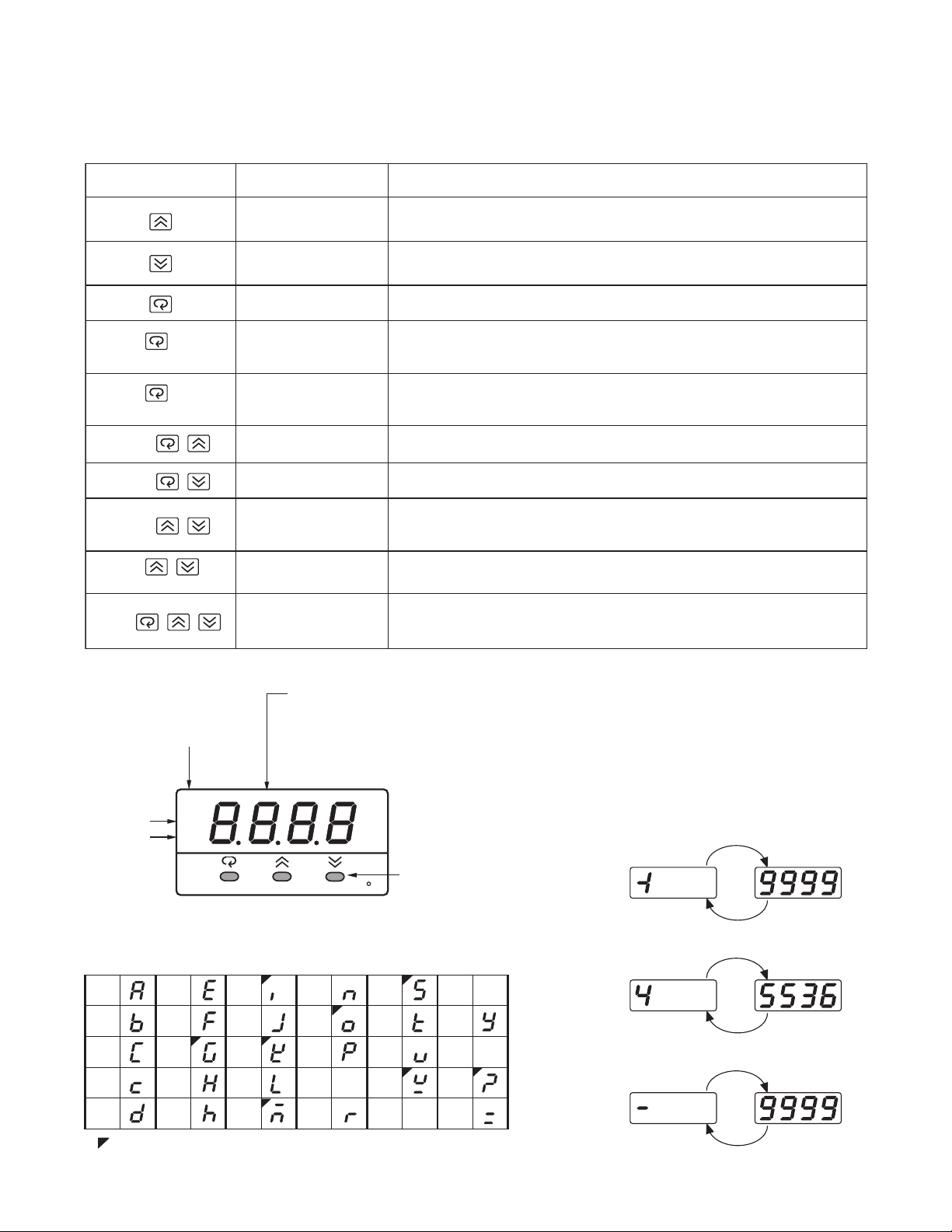
1-4 Keys and Displays
Pressand releasequickly to increase thevalue of parameter.
Pressand holdtoaccelerateincrementspeed.
Pressand releasequickly to decreasethe value of parameter.
Pressand holdtoaccelerate decrement speed.
Select the parameter in adirect sequence.
Allow access to more parametersonuser menu, also used to Enter manual
mode, auto-tune mode,defaultsetting modeand to save calibrationdata
duringcalibrationprocedure.
Select the parameter in a reverse sequenceduring menu scrolling.
Select the operation Mode in sequence.
Reset the frontdisplay to anormal display mode from anywhere within the
parameterbank. This also exits theauto-tuneand manual control
operation while quitting thesleep mode.
The controllerentersthe sleep modeifthe sleep function ( SLEP)is enabled
( selectYES ).
By entering correct security codeto allow execution of engineering programs.
This function is used onlyatthe factory to manage thediagnostic reports.
The user should never attempt to operate this function.
Press
for at least3seconds
Press
for at least6seconds
Press
Press
Press
Press
Press
for at least3seconds
Up Key
Down Key
Scroll Key
EnterKey
Start Record Key
Reverse Scroll Key
ModeKey
Reset Key
Sleep Key
Factory Key
NOITPIRCSEDNOITCNUFSYEKHCUOT
Reset historicalvaluesofPVHI and PVLO andstart to recordthe peak process
value.
Table 1.2 Keypad Operation
Output
Indicator
3 Silicone Rubber Buttons
4-digit Display
How to display a 5-digit number?
The unit is programmed by using three keys on the front panel. The available key functions are listed in following table.
Alarm 1
Indicator
Output 1
Indicator
2
O1
O2
A1
ETR-3400
Figure 1.4 Front Panel Layout
Table 1.3 Character Legend
A
B
C
c
Dh
: These characters are displayed with symbols
E
F
G
H
I
J
K
L
M
For a number with decimal point the
to display process value,
set point value, menu symbol,
parameter value, control output
value and error code etc.
N
O
P
Q
R
F
for ease of control setup
and set point adjustment.
S
T
U
V
W
X
Y
Z
?
=
5
display will be shifted one digit right:
-199.99 will be displayed by -199.9
4553.6 will be displayed by 4553
For a number without decimal point
the display will be divided into two
alternating phases:
-19999 will be displa ye d by:
45536 will be displayed by:
-9999 will be displaye d by:
Page 10
Power On
f
F
ETR-3400
O1
O2
A1
ETR-3400
O1
O2
A1
ETR-3400
O1
O2
A1
ETR-3400
All segments of display and
indicators are left off for 0.5
second.
Figure 1.5 Display Sequence o
Initial Power-up
F
All segments of display and
indicators are lit for 2 seconds.
F
Display program code of the
product for 2.5 seconds.
F
Each display stays for 1.25 seconds
The left diagram shows program
no. 0 ( for ETR-3400 ) with version
35.
F
Program Code
Program version
Program No.
O1
O2
A1
ETR-3400
O1
O2
A1
ETR-3400
O1
O2
A1
ETR-3400
O1
O2
A1
ETR-3400
Display Date Code and Serial
number for 2.5 seconds.
Each display stays for 1.25 seconds
Date Code
The left diagram shows Year 1998,
F
F
Month July ( 7 ), Date 31'st and
Serial number 192. This means that
the product is the 192'nd unit
produced on July 31'st, 1998.
Note that the month code stands for
October, BNovember C
stands for.
stands for and
December
A
Date (31st)
Month (December)
Year (1999)
Display used hours for 2.5
seconds.
The 6-digit number of hour is indicated
F
by two successive displays and each
one stays on for 1.25 seconds.
The left diagram shows that the
unit has been used for 23456.2
hours since production.
6
Page 11
g
*3
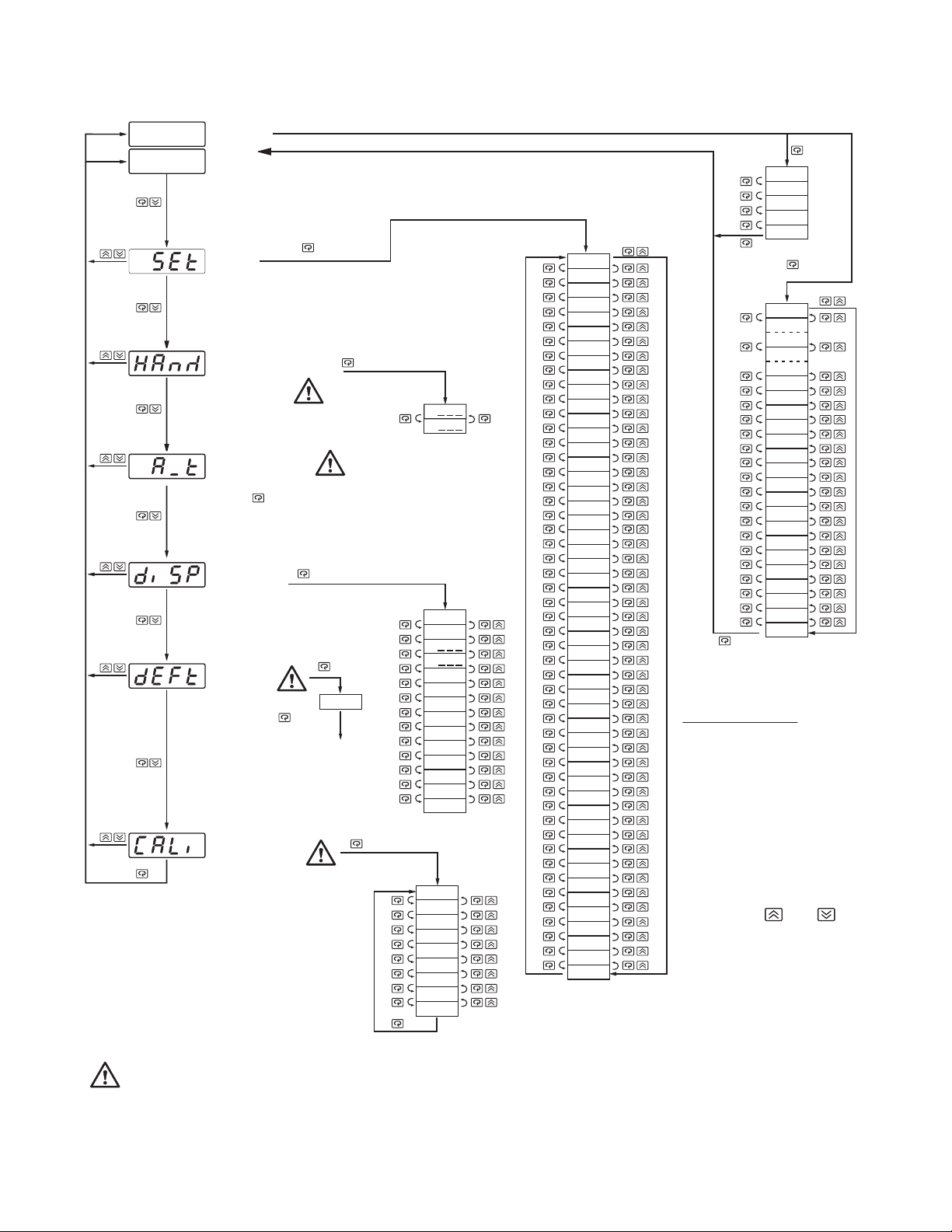
1-5 Menu Overview
User
Menu
or
PV Value
SV Value
Setup
Menu
Hand (Manual)
Control
Mode
Auto-tuning
Mode
Pressfor 3 secondsto enter
the auto-tuning mode
Display
Mode
Default
Setting
Mode
3 seconds
FILE
for
To execute the
default setting
program
Calibration
Mode
Entering these modes will break the control loop and
change some of the previous setting data. Make sure that
settings are properly backed up prior to initiating if they
are to be used again.
for3seconds
H
C
PVHI
PVLO
H
C
DV
PV1
PV2
PB
TI
TD
CJCT
PVR
PVRH
PVRL
AD0
ADG
V1G
CJTL
CJG
REF1
SR1
MA1G
V2G
*2
SEL1
SEL2
SEL3
SEL4
*1
FUNC
COMM
PROT
ADDR
BAUD
DATA
PARI
STOP
AOFN
AOLO
AOHI
IN1
IN1U
DP1
IN1L
IN1H
IN2
IN2U
DP2
IN2L
IN2H
OUT1
O1TY
CYC1
O1FT
OUT2
O2TY
CYC2
O2FT
A1FN
A1MD
A1FT
A2FN
A2MD
A2FT
EIFN
PVMD
FILT
SELF
SLEP
SPMD
SP1L
SP1H
SP2F
DISF
SEL1
SEL2
SEL3
SEL4
SEL5
*1:
The flow chart shows a complete listing of all parameters.
For actual application the number of available parameters
depends on setup conditions, and should be less
than that shown in the flow chart. See Appendix A for the
existence conditions of each parameter.
You can select at most 5 parameters to put in front of the
*2:
user menu by using SEL1 to SEL5 located at the end of
the setup process
*3:
Set DISF (display format) value in the setup menu to
chan
e between PV (Process Value) and SV (Setpoint Value)
Display Return
The menu will return to
displaying the selected
PV or SV after 2 min.
if no entry is made
except, when in the
Display Mode or in the
Manual Mode.
However, the menu can
return to the selected PV
or SV display at any time
by pressing and .
SEL5
*1
TIME
A1SP
A1DV
A2SP
A2DV
RAMP
OFST
REFC
SHIF
PB1
TI1
TD1
CPB
DB
SP2
PB2
TI2
TD2
O1HY
A1HY
A2HY
PL1
PL2
for 3
seconds
7
Page 12

1-6 System Modes
Priority
The controller performs a closed loop control mode under its normal control mode operation. The controller will
maintain its normal control mode when you are operating the user menu, setup menu or display mode, reloading
default values or applying an event input signal. Under certain conditions the normal control mode will transfer
to an Exception Mode. The exception modes include : Sleep Mode, Manual Mode, Failure Mode, Calibration
Mode and Auto Tuning Mode. All these modes perform in an open loop control except the auto-tuning mode
which performs ON-OFF plus PID close loop control. The mode transfer is governed by the priority as shown in
Figure 1.6.
Figure 1.6 System Mode Priority
High
Low
? Mode
Sleep Mode?
Yes
No
Manual Mode?
Yes
System Modes
Sleep Mode: See Section 4-11
Manual Mode: See Section 3-23
Failure Mode: See Section 3-17
Calibration Mode: See Chapter 6
Auto-tuning Mode: See Section 3-20
Normal Control Mode: See Section 3-24, 3-26, 4-1
No
Failure Mode?
Yes
No
Request
Calibration
Mode
Request
Auto-tuning
Mode
Request
Normal
Control
Mode
The calibration mode, auto-tuning mode and normal control mode are in the same priority level.
8
Page 13
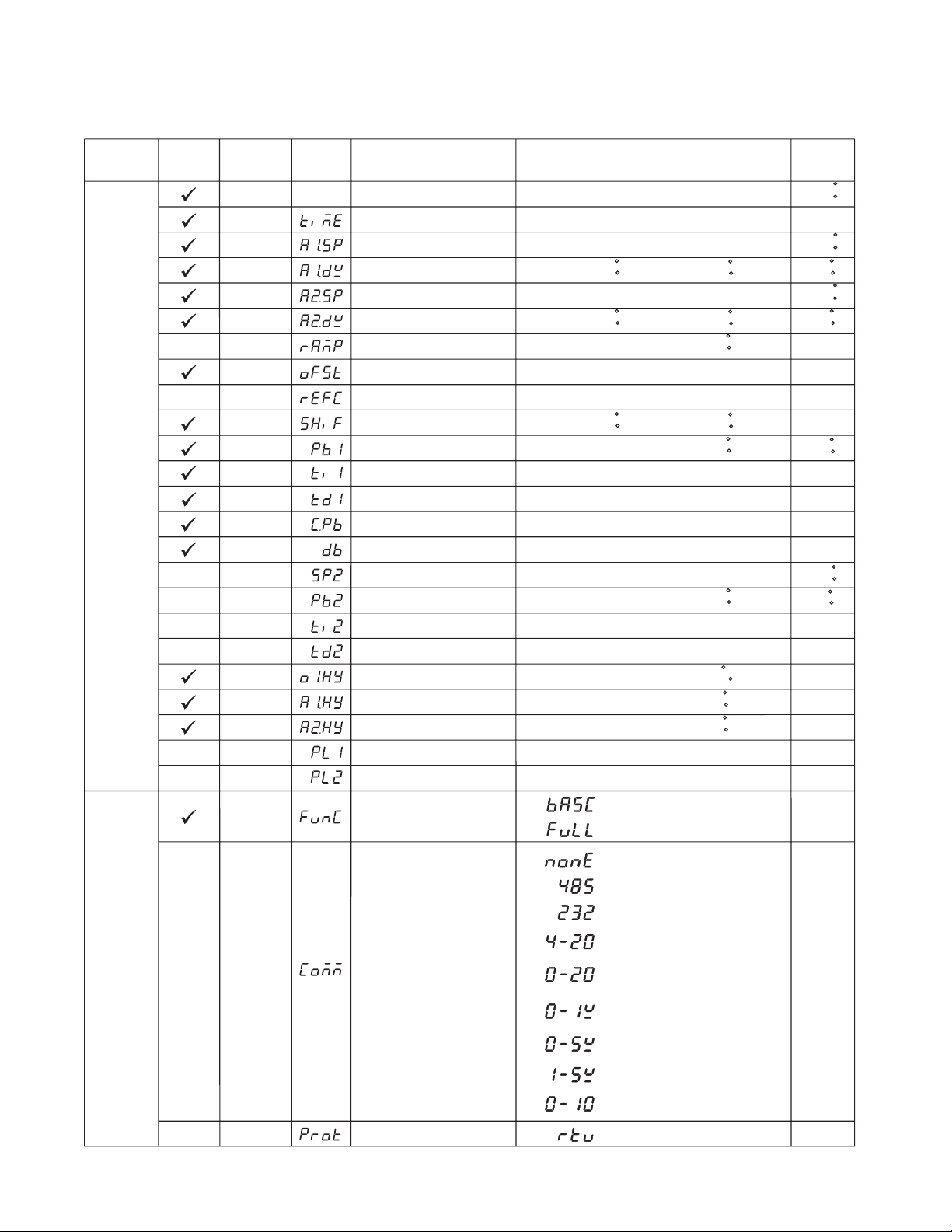
1-7 Parameter Descriptions
Table 1.4 Parameter Description (1 of 7)
Contained
in
Basic
Function
Menu
Parameter
Notation
SP1
TIME
A1SP
A1DV
A2SP
A2DV
RAMP
OFST
REFC
SHIF
PB1
TI1User
TD1
CPB
DB
SP2
PB2
TI2
TD2
O1HY
A1HY
A2HY
PL1
PL2
FUNC
Display
Format
Parameter
Description
Set point1
DwellTime
Alarm 1Set point
Alarm 1 DeviationValue
Alarm 2Set point
Alarm 2 DeviationValue
Ramp Rate
Offset Value forPcontrol
Reference Constantfor
Specific Function
PV1 Shift (offset) Value
Proportional Band 1Value
IntegralTime 1Value
DerivativeTime 1Value
Cooling Proportional Band
Value
Heating-CoolingDead Band
NegativeValue= Overlap
Set point2
Proportional Band 2Value
IntegralTime 2Value
DerivativeTime 2Value
Output1ON-OFFControl
Hysteresis
Hysteresis ControlofAlarm 1
Hysteresis ControlofAlarm 2
Output1Power Limit
Output2Power Limit
Function Complexity Level
Low:
Low:
SeeTable 1.5, 1.6
Low:
SeeTable 1.5, 1.7
Low:
Low:
Low:
Low:
Low:
Low:
Low:
Low:
Low:
Low:
SeeTable 1.5, 1.8
Low:
Low:
Low:
Low:
Low:
Low:
Low:
Low:
0
1
SP1L SP1H
0 6553.5 minutes 0.0
-200.0 C
(-360.0 F)
-200.0 C
(-360.0 F)
0
0
-200.0 C
(-360.0 F)
0
0
0
1
-36.0
0
0
0
0.1
0.1
0.1
0
0
:
Basic Function Mode
Full Function Mode
:
Range
High:
High:
High:
High:
High:
High:
High:
High:
High:
High:
High:
High:
High:
High:
High:
High:
High:
High:
High:
High:
High:
200.0 C
( 360.0F)
200.0 C
( 360.0F)
500.0C
(900.0 F)
100.0 %
60
200.0 C
( 360.0F)
500.0C
(900.0 F)
1000 sec
360.0 sec
255 %
36.0%
500.0C
(900.0 F)
1000 sec
360.0 sec
55.6C
( 100.0F)
10.0C
(18.0F)
10.0C
(18.0F)
100%
100%
Default
Value
100.0C
(212.0 F)
100.0C
(212.0 F)
10.0C
(18.0 F)
100.0C
(212.0 F)
10.0C
(18.0 F)
0.00
25.0
2
0.0
10.0C
(18.0 F)
100
25.0
100
0
37.8 C
(100.0 F)
10.0C
(18.0F)
100
25.0
0.1
0.1
0.1
100
100
1
Setup
Menu
COMM
PROT
Communication Interface
Type
COMM Protocol Selection
9
:
0
1
2
3
4
5
6
7
8
0
No communication function
:
RS-485 interface
:
RS-232 interface
:
4-20 mA analog retransmission
output
:
0-20 mA analog retransmission
output
:
0-1V analog retransmission
output
:
0-5V analog retransmission
output
:
1-5V analog retransmission
output
:
0-10V analog retransmission
output
Modbus protocol RTU mode
:
1
0
Page 14
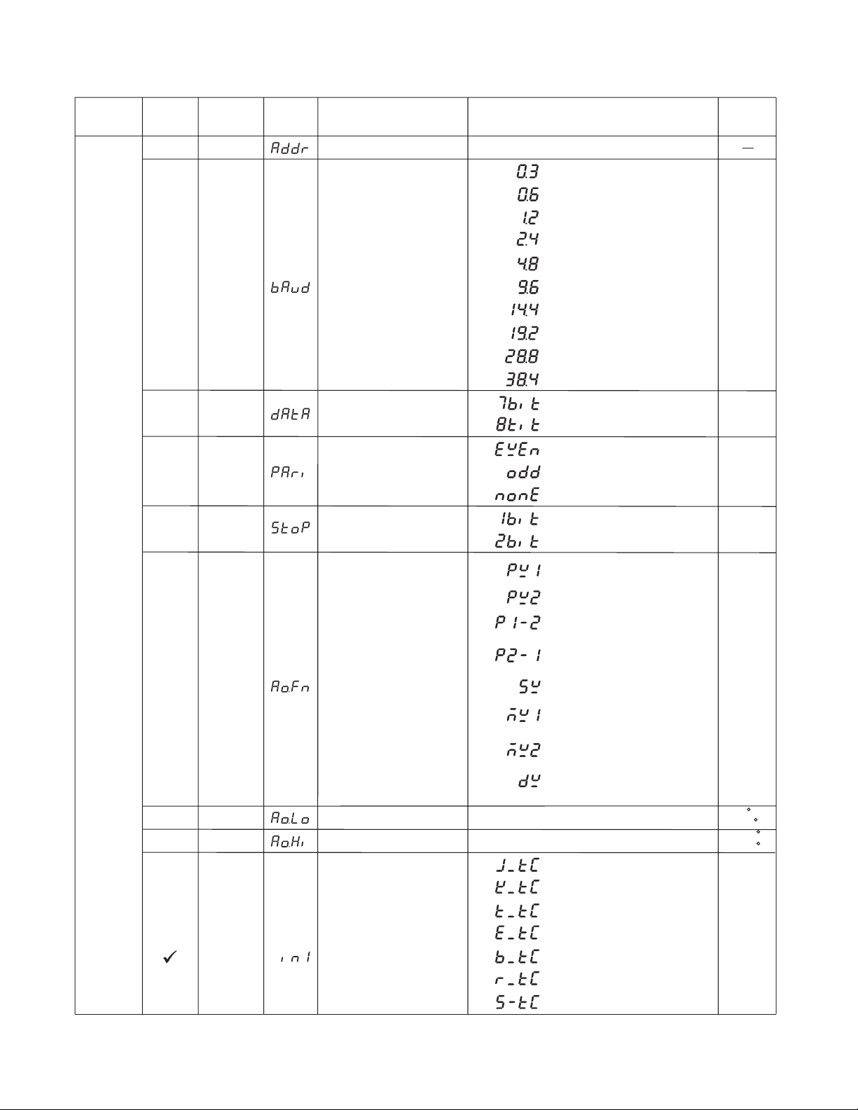
Table 1.4 Parameter Description (continued 2 of 7)
Contained
in
Basic
Function
Parameter
Notation
ADDR
Display
Format
Address Assignmentof Digital
COMM
BAUD
DATA
PARI
Baud Rateof Digital COMM
DataBit countof Digital
COMM
ParityBit of Digital COMM
Parameter
Description
Range
Low:
:
0
1
2
3
4
5
6
7
8
9
0
18data bits
0
1
2
0.3Kbits/s baudrate
:
0.6Kbits/s baudrate
:
1.2Kbits/s baudrate
:
2.4Kbits/s baudrate
:
4.8Kbits/s baudrate
:
9.6Kbits/s baudrate
:
14.4Kbits/s baudrate
:
19.2Kbits/s baudrate
:
28.8Kbits/s baudrate
:
38.4Kbits/s baudrate
:
7 data bits
:
Even parity
:
Odd parity
:
No parity bit
:
High:
Default
Value
5521
5
1
0
Setup
Menu
STOP
AOFN
AOLO
AOHI
IN1
Stop Bit Countof Digital
COMM
Analog Output Function
Analog OutputLow Scale
Value
Analog Output High Scale
Value
IN1 SensorType Selection
0
1
0
1
2
3
4
5
6
7
Low:
Low:
0
1
2
3
4
5
6
:
One stop bit
:
Two stop bits
:
RetransmitIN1 process value
:
RetransmitIN2 process value
:
RetransmitIN1 IN2 difference
process value
:
RetransmitIN2 IN1 difference
process value
:
Retransmitset point value
:
Retransmit output1manipulation
value
:
Retransmit output2manipulation
value
:
Retransmit deviation(PV-SV)
Value
-19999
-19999
:
:
:
:
:
:
:
Jtypethermocouple
Ktypethermocouple
Ttypethermocouple
Etypethermocouple
Btypethermocouple
Rtypethermocouple
Stypethermocouple
High:
High:
45536
45536
0
0
0C
(32.0F)
100.0C
(212.0F)
1
(0)
10
Page 15
Table 1.4 Parameter Description (continued 3 of 7)
Contained
in
Basic
Function
Parameter
Notation
Display
Format
Setup
Menu
IN1
IN1U
DP1
IN1L
IN1H
IN1 Sensor Type Selection
IN1 Unit Selection
IN1 Decimal Point Selection
IN1 Low Scale Value
IN1 High Scale Value
Parameter
Description
7
8
9
10
11
12
13
14
15
16
17
0
1
2
0
1
2
3
Low:
Low:
Range
:
N type thermocouple
:
L type thermocouple
:
PT 100 ohms DIN curve
:
PT 100 ohms JIS curve
:
4-20 mA linear current input
:
0-20 mA linear current input
:
0-1V linear Voltage input
:
0-5V linear Voltage input
:
1-5V linear Voltage input
:
0-10V linear Voltage input
:
Special defined sensor curve
:
Degree C unit
:
Degree F unit
:
Process unit
:
No decimal point
:
1 decimal digit
:
2 decimal digits
:
3 decimal digits
-19999
-19999
High:
High:
45536
45536
Default
Value
1
(0)
0
(1)
1
0
1000
IN2
IN2U
DP2
IN2L
IN2H
OUT1
O1TY
IN2 Signal Type Selection
IN2 Unit Selection
IN2 Decimal Point Selection
IN2 Low Scale Value
IN2 High Scale Value
Output 1 Function
Output 1 Signal Type
0
1
4
5
6
7
20
SameasIN1U
Sameas DP1
-19999
Low:
-19999
Low:
0
1
0
1
2
3
:
IN2 no function
:
Current transformer input
:
0-1V linear voltage input
:
0-5V linear voltage input
:
1-5V linear voltage input
:
0-10V linear voltage input
Perform Event input function
:
High:
45536
High:
45536
:
Reverse (heating ) control action
:
Direct (cooling) control action
Relay output
:
Solid state relay drive output
:
Solid state relay output
:
:
4-20 mA current module
1
2
1
0
1000
0
0
11
Page 16
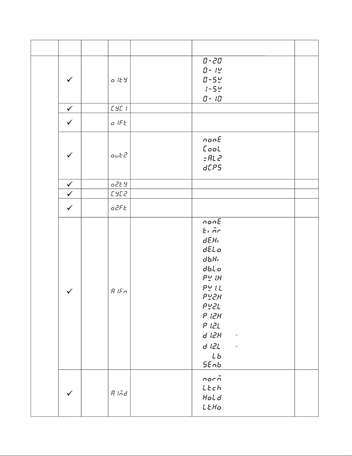
Table 1-4 Parameter Description (continued 4 of 7)
Contained
in
Basic
Function
Parameter
Notation
Display
Format
O1TY
CYC1
O1FT
Output 1 Signal Type
Output 1 CycleTime
Output 1 Failure Transfer
Mode
Parameter
Description
Range
4
5
6
7
8
Low:
SelectBPLS(bumpless transfer)or 0.0 ~ 100.0
%to continue output1control function as the unit
fails, power starts or manual mode starts.
:
0-20 mA current module
0-1V voltage module
:
0-5V voltage module
:
1-5V voltage module
:
0-10V voltage module
:
0.1
High:
100.0 sec 18.0
Default
Value
0
BPLS
Setup
Menu
OUT2
O2TY
CYC2
O2FT
A1FN
Output 2 Function
Output 2 Signal Type
Output 2 Cycle Time
Output 2 Failure Transfer
Mode
Alarm1Function
0
1
2
3
: Output2no function
:PID cooling control
:Perform alarm2function
:DC power supply module
installed
Sameas O1TY
High:
0.1
Low:
SelectBPLS(bumpless transfer)or 0.0 ~ 100.0
%to continue output2control function as the unit
fails, power starts or manual mode starts.
0
1
2
3
4
5
6
7IN1 process value low alarm
8 IN2 process value high alarm
9
10
11
12
13
14 Loop break alarm
15 Sensor break or A-D fails
:
No alarm function
:
Dwell timer action
:
Deviation high alarm
:
Deviation low alarm
:
Deviation band outof band alarm
:
Deviation band in band alarm
:
IN1 process value high alarm
:
:
:
IN2 process value low alarm
IN1or IN2 process value high
:
alarm
:
IN1or IN2 process value low
alarm
:
IN1 IN2 difference process value
high alarm
:
IN1 IN2 difference process value
low alarm
:
:
100.0 sec
2
0
18.0
BPLS
2
A1MD
Alarm1Operation Mode
12
0
1
2
3
:
Normal alarm action
Latching alarm action
:
:
Hold alarm action
Latching & actionHold
:
0
Page 17

Table 1-4 Parameter Description (continued 5 of 7)
Contained
in
Basic
Function
Parameter
Notation
A1FT
Display
Format
Alarm 1 FailureTransfer
Mode
A2FN
A2MD
A2FT
Alarm 2 Function
Alarm 2 Operation Mode
Alarm 2 FailureTransfer
Mode
Parameter
Description
Range
:
0
1
Same as A1FN
Same as A1MD
Same as A1FT
0
1SP2 activated to replace SP1
2
3
4
Alarm output OFF as unit fails
:
Alarm outputONas unit fails
Event input no function
:
:
PB2, TI2, TD2 activatedtoreplace
:
PB1, TI1, TD1
:
SP2,PB2,TI2, TD2 activated to
replace SP1,PB1, TI1, TD1
Reset alarm 1 output
:
Default
Value
1
2
0
1
Setup
Menu
EIFN
Event Input Function
PVMD PV Mode Selection
FILT
Filter DampingTime
ConstantofPV
10
:
5
6
7
8
9
0
1
2
3
0
1
2
3
4
5
6
7
8
9
Reset alarm 2 output
:
Reset alarm1&alarm 2
Disable Output1
:
Disable Output2
:
Disable Output1&Output2
:
:
LockAll Parameters
:
Use PV1 as process value
:
Use PV2 as process value
:
Use PV1 PV2 (difference) as
process value
:
Use PV2 PV1 (difference) as
process value
:
0 second time constant
:
0.2 second time constant
:
0.5 second time constant
:
1 second time constant
:
2 seconds time constant
:
5 seconds time constant
:
10 seconds time constant
:
20 seconds time constant
:
30 seconds time constant
:
60 seconds time constant
1
0
2
SELF
SLEP
SelfTuning Function
Selection
Sleep mode Function
Selection
13
0
1
0
1
:
Self tune function disabled
:
Self tune function enabled
:
Sleep mode function disabled
:
Sleep mode function enabled
0
0
Page 18
:
:
SP2F
DISF
Formatof set point2Value
Display Format
0
1
set point 2(SP2) is an actual value
set point 2(SP2) isadeviation
value
0
:
:
:
:
:
:
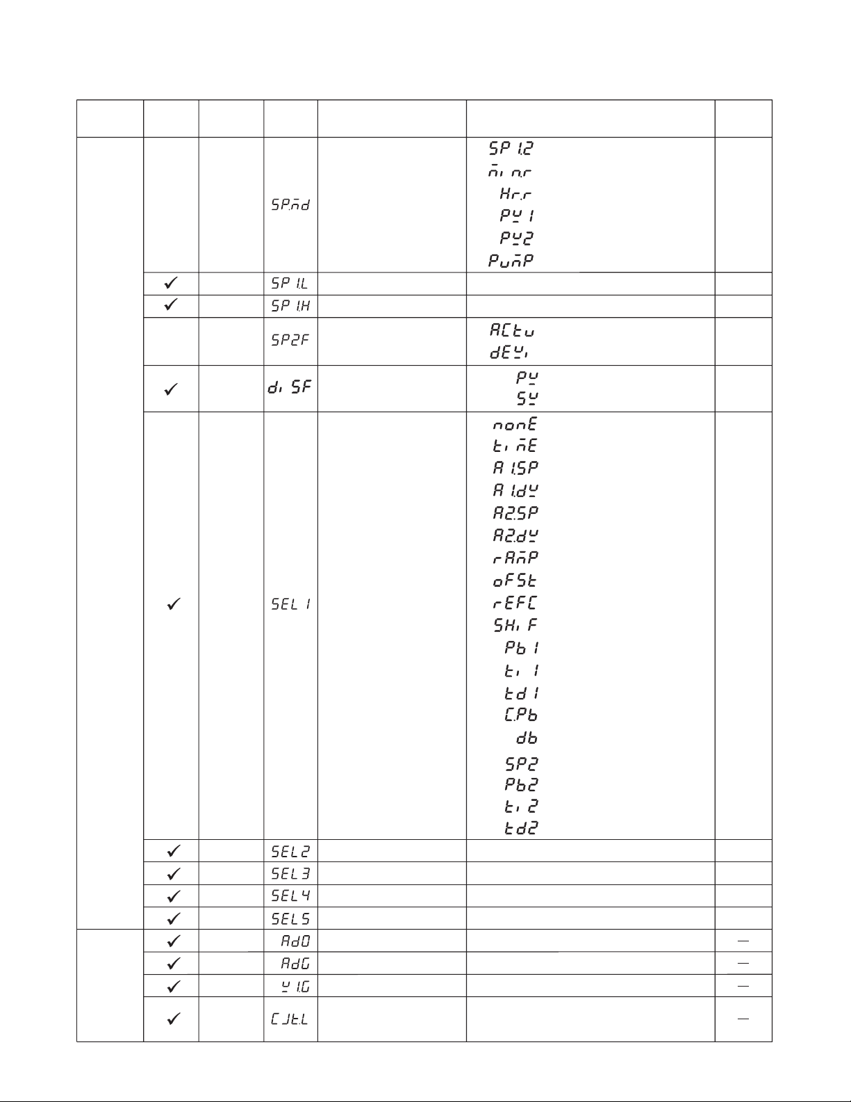
SPMD Set point Mode Selection
0
1
2
3
4
5
Use SP1 or SP2 (depends on EIFN)
as setpoint
Use minute ramp rate as set point
Use hour ramp rateas set point
Use IN1 processvalueas set point
Use IN2 processvalueas set point
Selected for pump control
SEL1 Select 1'st Parameter
0
:
:
:
:
:
:
:
:
:
:
:
:
:
:
:
:
:
:
:
:
16
17
18
ParameterPB2 put ahead
Parameter TI2 put ahead
ParameterTD2 put ahead
0
0
1
1
2
3
4
5
6
No parameter put ahead
Display PV value
Display SV value
Parameter TIME put ahead
ParameterA1SP put ahead
ParameterA1DV put ahead
ParameterA2SP put ahead
ParameterA2DV put ahead
ParameterRAMP put ahead
ParameterOFST put ahead
ParameterREFC put ahead
ParameterSHIF put ahead
ParameterPB1 put ahead
Parameter TI1 put ahead
ParameterTD1 put ahead
ParameterCPB put ahead
ParameterSP2 put ahead
7
8
9
10
11
12
13
14
15
ParameterDB put ahead
0
SEL2
SEL3
SEL4
Same as SEL1
Same as SEL1
Same as SEL1
0
0
0
Low:
Low:
High:
High:
SP1L
SP1H
SP1Low Scale Value
SP1High Scale Value
-19999
-19999
45536
45536
0C
(32.0F)
1000.0 C
(1832.0 F)
Table 1-4 Parameter Description (continued 6 of 7)
Select 2'ndParameter
Select 3'rd Parameter
Select 4'th Parameter
Select 5'th Parameter
SEL5
Same as SEL1
0
AD0
ADG
V1G
AtoDZero Calibration
Coefficient
AtoDGain Calibration
Coefficient
Voltage Input1Gain
Calibration Coefficient
-360 360
-199.9 199.9
-199.9 199.9
Low:
Low:
Low:
High:
High:
High:
Low:
High:
CJTL
ColdJunction Low
Temperature Calibration
Coefficient
-5.00C 40.00 C
Calibration
Mode
Menu
Setup
Menu
:
Parameter
Description
Range
Default
Value
Contained
in
Basic
Function
Parameter
Notation
Display
Format
14
Page 19

Table 1.4 Parameter Description (continued 7 of 7)
Contained
in
Calibration
Mode
Menu
Display
Mode
Menu
Basic
Function
Parameter
Notation
CJG
REF1
SR1
MA1G
V2G
PVHI
PVLO
MV1
MV2
DV
PV1
PV2
PB
TD
CJCT
PVR
PVRH
PVRL
Display
Format
Cold Junction Gain
Calibration Coefficient
Reference Voltage 1
Calibration Coefficientfor
RTD1
Serial Resistance 1
Calibration Coefficientfor
RTD1
mA Input1Gain Calibration
Coefficient
Voltage Input2Gain
Calibration Coefficient
Historical Maximum Valueof
PV
Historical Minimum Valueof
PV
Current Output 1Value
Current Output 2Value
Current Deviation(PV-SV)
Value
IN1 Process Value
IN2 Process Value
Current Proportional Band
Value
TI
Current Integral Time Value
Current Derivative Time
Value
ColdJunction Compensation
Temperature
Current Process Rate Value
Maximum Process Rate Value
Minimum Process Rate Value
Parameter
Description
Range
-199.9
Low:
-199.9
Low:
-199.9
Low:
-199.9
Low:
-199.9 199.9
Low:
-19999
Low:
-19999
Low:
Low:
Low:
Low:
Low:
Low:
Low:
Low:
Low:
Low:
Low:
Low:
Low:
0
0
-12600
-19999
-19999
0
0
0
-40.00C
-16383
-16383
-16383
High:
High:
High:
High:
High:
High:
High:
High:
High:
High:
High:
High:
High:
High:
High:
High:
High:
High:
High:
199.9
199.9
199.9
199.9
45536
45536
100.00 %
100.00 %
12600
45536
45536
500.0 C
(900.0 F)
4000 sec
1440 sec
90.00C
16383
16383
16383
Default
Value
15
Page 20

Table 1.5 Input (IN1 of IN2) Range
Range
Range
InputType
, A2SP or SP2 is configured with respect to
CT input, its adjustment range is unlimited.
Range Low
Range High
J_TC
-120C
(-184 F)
1000 C
(1832 F)
K_TC
-200C
(-328 F)
1370C
(2498 F)
T_TC
-250 C
(-418 F)
400 C
(752 F)
E_TC
-100 C
(-148 F)
900 C
(1652F)
B_TCCTR_TC
0C
(32 F)
1820 C
(3308F)
0C
(32 F)
1767.8C
(3214F)
S_TC
0C
(32F)
1767.8 C
(3214F)
Input Type
Range Low
Range High
N_TC
-250 C
(-418 F)
1300 C
(2372 F)
L_TC
-200 C
(-328 F)
900 C
(1652 F)
Table 1.6 Range Determination for A1SP
If A1FN =
of A1SP
same as range of
PV1.H, PV1.L
Table 1.7 Range Determination for A2SP
If A2FN=
Range of A2SP
sameas range of
PV1.H, PV1.L
Table 1.8 Range Determination for SP2
If PVMD =
of SP2
same as range of
IN1
IN1
PV1
IN1
PT.DN
-210 C
(-346 F)
700C
(1292 F)
PT.JS
-200 C
(-328 F)
600C
(1112F)
PV2.H,PV2.L
PV2.H,PV2.L
0 Amp
90 Amp
IN2
IN2
PV2
IN2
Linear (V, mA)
or SPEC
-19999
45536
P1.2.H, P1.2.L
D1.2.H, D1.2.L
IN1, IN2
P1.2.H, P1.2.L
D1.2.H, D1.2.L
IN1,IN2
P1 2, P2 1
IN1, IN2
Exception:If any of A1SP
16
Page 21
Chapter 2
22.2
Dangerous voltages capable of causing death are sometimes present in this instrument. Before
installation or beginning any troubleshooting procedures the power to all equipment must be
switched off and isolated. Units suspected of being faulty must be disconnected and removed to
a safe location.
To minimize the possibility of fire or shock hazards, do not expose this instrument to rain or excessive moisture. This control is not to be used in hazardous locations.
Do not use this instrument in areas under hazardous conditions such as excessive shock, vibration, dirt, moisture, corrosive gases or oil. The controller is only intended for installation in safe
areas, or inside properly rated enclosures.
2-1 Unpacking
Upon receipt of the shipment remove the unit from the carton and inspect the unit for shipping damage.
If any damage due to transit is noticed, report and file a claim with the carrier. Record the model number, serial
number, and date code for future reference when corresponding with our service center. The serial number (S/N)
and date code (D/C) are labeled on the box and the housing of the control.
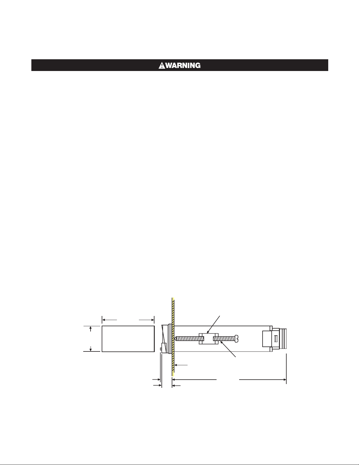
2-2 Mounting
Make panel cutout to dimension shown in Figure 2.1. Take both mounting clamps away and insert the controller
into panel cutout.
Install the mounting clamps back. Gently tighten the screws in the clamp till the
controller front panels is fitted snugly in the cutout.
MOUNTING
CLAMP
SCREW
98.0mm
+0.3
_
+0.5
_
45
0
0
Panel
12.5mm
10.0mm
Figure 2.1 Mounting Dimensions
17
Page 22
2-3 Wiring Precautions
C
Fuse
Before wiring, verify the label for correct model number and options. Switch off the power while checking.
Care must be taken to ensure that maximum voltage rating specified on the label is not exceeded.
It is recommended that power of these units to be protected by fuses or circuit breakers rated at the minimum
value possible.
All units should be installed inside a suitably grounded metal enclosure to prevent live parts being accessible from
human hands and metal tools.
All wiring must conform to appropriate standards of good practice and local codes and regulations. Wiring must
be suitable for voltage, current, and temperature rating of the system.
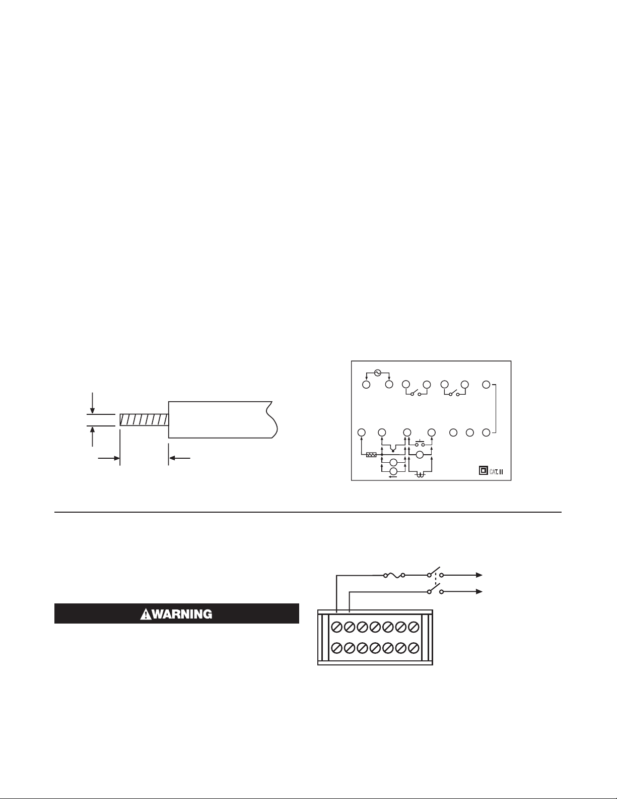
The “ stripped “ leads as specified in Figure 2.2 below are used for power and sensor connections.
Beware not to over-tighten the terminal screws.
Unused control terminals should not be used as jumper points as they may be internally connected, causing damage to the unit.
Verify that the ratings of the output devices and the inputs as specified in Chapter 8 are not exceeded.
Electric power in industrial environments contain a certain amount of noise in the form of transient voltage and
spikes. This electrical noise can enter and adversely affect the operation of microprocessor-based controls. For
this reason we strongly recommend the use of shielded thermocouple extension wire which connects the sensor
to the controller. This wire is a twisted-pair construction with foil wrap and drain wire. The drain wire is to be attached to ground at one end only.
Figure 2.2 Lead Termination
2.0mm
0.08" max.
4.57.0 mm
~
0.18" 0.27"
~
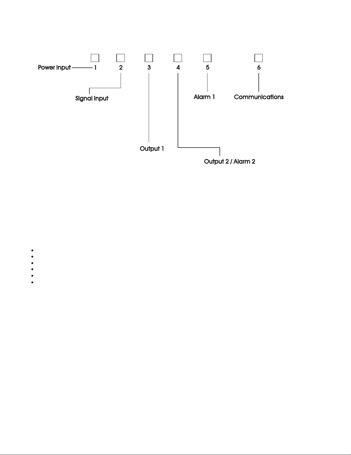
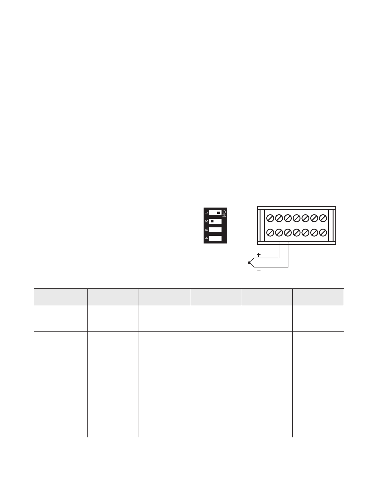
2-4 Power Wiring
The controller can operate at 11-26 VAC / VDC or
90-264VAC. Check that the installation voltage corresponds with the power rating indicated on the product
label before connecting power to the controller.
This equipment is designed for installation in
an enclosure that will provide adequate protection against electric shock. The enclosure
must be connected to earth ground.
Local requirements regarding electrical installation should be rigidly observed. Consideration should be given to prevent unauthorized
persons access to the power terminals.
Figure 2.3 Rear Terminal Connection Diagram
OUT2
ALM2
+
3
2
1
N
L
PTA
A
12
8910
90-264VAC
47-63 Hz,15VA
8 9
RTD
34
TC+
PTB PTB
+
B
+
V
I
5
11
121314
V,CT
EI ,TC
_
B
_
67
2A/240VAC 2A/240VAC
__
__
10
_
CT
_
Figure 2.4 Power Supply Connections
_
4
V+ ,CT+
EI+,COM
11
++
V
OUT1
_
+
5
6
AO
AO+
TX1 TX2
12 13 14
ALM1
+
)TUPTUOCIGOL(1MLA
7
_
_
ALM1
CAT. II
~
90 264 VA Cor
11 26 VAC/VD
~
18
Page 23
2-5 Sensor Installation Guidelines
Figure 2.5 Thermocouple Input Wiring
DIP Switch
Thermocouple
Type
Cable
Material
British
BS
American
ASTM
German
DIN
French
NFE
T
J
Copper ( Cu )
Constantan
( Cu-Ni )
+ blue
red
* blue
+ red
brown
* brown
+ yellow
blue
* blue
Iron ( Fe )
Constantan
( Cu- Ni )
+ white
red
* black
+ red
blue
* blue
+ yellow
black
* black
K
Nickel-Chromium
( Ni-Cr )
Nickel-Aluminum
( Ni-Al )
+ brown
blue
* red
+ yellow
red
* yellow
+ red
green
* green
+ yellow
purple
* yellow
R
S
Pt-13%Rh,Pt
Pt-10%Rh,Pt
+ white
blue
* green
+ black
red
* green
+ red
white
* white
+ yellow
green
* green
B
Pt-30%Rh
Pt-6%Rh
+grey
red
* grey
Table 2.1 Thermocouple Cable Color Codes
*Color of overall sheath
+ white
blue
* blue
+ yellow
blue
* black
Use
Copper Wire
Use
Copper Wire
+red
grey
* grey
Proper sensor installation can eliminate many problems in a control system. The probe should be placed so that it
can detect any temperature change with minimal thermal lag. In a process that requires fairly constant heat output,
the probe should be placed close to the heater. In a process where the heat demand is variable, the probe should
be close to the work area. Some experiments with probe location are often required to find this optimum position.
In a liquid process, addition of a stirrer will help to eliminate thermal lag. Since the thermocouple is basically a point
measuring device, placing more than one thermocouple in parallel can provide an average temperature readout
and produce better results in most air heated processes.
Proper sensor type is also a very important factor to obtain precise measurements. The sensor must have the
correct temperature range to meet the process requirements. In special processes the sensor might need to have
different requirements such as leak-proof, anti-vibration, antiseptic, etc.
Standard sensor limit s of error are 4˚F (2˚C) or 0.75% of sensed temperature (half that for special) plus drift caused
by improper protection or interference.
2-6 Thermocouple Input Wiring
Proper sensor installation can eliminate many problems. Thermocouple input connections are shown in
Figure 2.5. The correct type of thermocouple extension
lead-wire or compensating cable must be used for the
distance between the controller and the thermocouple,
ensuring that the correct polarity is observed throughout. Joints in the cable should be avoided, if possible.
If the length of thermocouple plus the extension wire is
too long, it may affect the temperature measurement.
A 400 ohms K type or a 500 ohms J type thermocouple
should be used.
O
1
N
2
3
4
12
8910
34
11
5
67
121314
+
19
Page 24
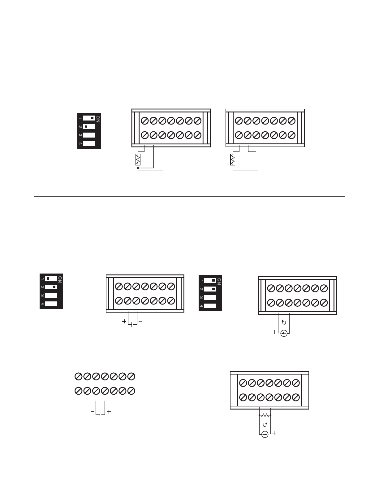
2-7 RTD Input Wiring
Figure 2.6 RTD Input Wiring
DIP Switch
DIP Switch
DIP Switch
Figure 2.10 Input 2 Linear Current Wiring
IN2 = 0-5 V or 1-5 V
Figure 2.9 Input 2 Linear Voltage Wiring
1~5V, 0~10V
RTD connections are shown in Figure 2.6, with the compensating lead connected to terminal 9. For two-wire RTD
inputs, terminals 9 and 10 should be linked. The three-wire RTD offers the capability of lead resistance compensation provided that the third wire is installed into PIN 9 as shown in Figure 2.6.
Two-wire RTD should be avoided, if possible, for the purpose of accuracy. A 0.4 ohm lead resistance of a two-wire
RTD will produce a 1° C temperature variance every 50ft of lead length.
O
1
N
2
3
4
12
8910
34
11
5
67
121314
12
8910
34
11
5
67
121314
RTD RTD
Three-Wire RTD
Two-Wire RTD
2-8 Linear DC Input Wiring
DC linear voltage and linear current connections for input 1 are shown in Figure 2.7 and Figure 2.8 .
DC linear voltage and linear current connections for input 2 are shown in Figure 2.9 and Figure 2.10 .
Figure 2.7 Input 1 Linear Voltage Wiring
O
1
N
2
3
4
12
8910
34
11
5
121314
67
Figure 2.8 Input 1 Linear Current Wiring
O
1
N
2
3
4
12
8910
34
11
5
121314
67
0~1V, 0~5V
1~5V, 0~10V
5
34
12
8910
11
0~1V, 0~5V
67
121314
+
+
20
0~20 mA or
4~20 mA
12
8910
0~20 mA or
4~20 mA
+
5
34
11
121314
R = 250 Ohms
+
67
Page 25
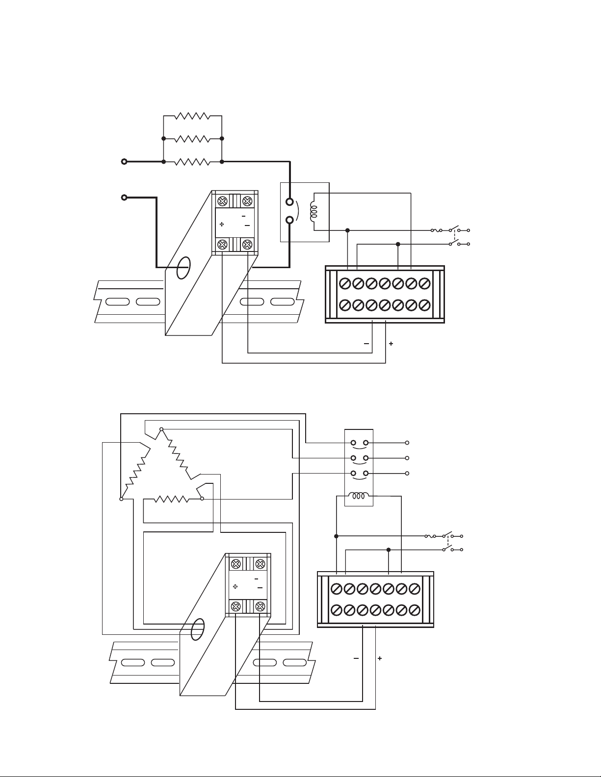
2-9 CT/Heater Current Input Wiring
Figure 2.11 CT Input Wiring for Single Phase Heater
Supply
Figure 2.12 CT Input Wiring for Three Phase Heater
Make sure the total current through CT94-1 does not exceed 50A rms
Supply
Heater 1
Heater 2
Heater Supply
DIN Rail
Heater 3
Current Transformer
CT94 1
+
1
2
Contactor
34
12
8910
Contactor
Fuse
5
67
11
121314
+
CT Signal Input
Main
Current Transformer
CT941
+
1
2
DIN Rail
12
8910
5
34
11
121314
+
CT Signal Input
Three Phase
Heater Power
Fuse
Main
67
21
Page 26
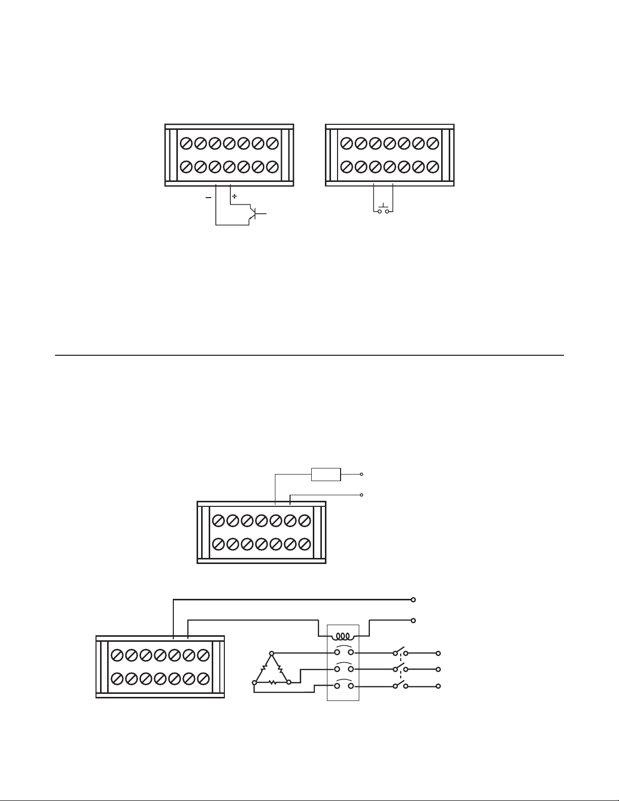
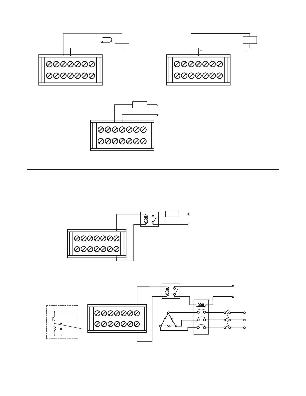
2-10 Event Input Wiring
Open Collector Input
Figure 2.13 Event Input Wiring
12
8910
34
11
121314
+
67
5
The event input can accept a switch signal as well
as an open collector signal. The event input function
(EIFN) is activated as the switch is closed or an open
collector signal is initiated.
Also refer to Section 4-1 for event input function.
2-11 Output 1 Wiring
Figure 2.14 Output 1 Wiring
34
12
8910
Switch Input
5
11
121314
67
12
8910
5
12
34
67
8910
11
121314
Relay or Triac (SSR) Output to Drive Contactor
Max. 2A
Resistive
Load
5
34
11
121314
67
Relay Output Direct Drive
Three Phase Delta
Heater Load
Contactor
120V/240V
Main Supply
120V /240V
Main Supply
Three
Phase
Heater
Power
No Fuse
Breaker
22
Page 27
120V/240V
Main Supply
Max. 2A
Resistive
Load
Relay Output Direct Drive
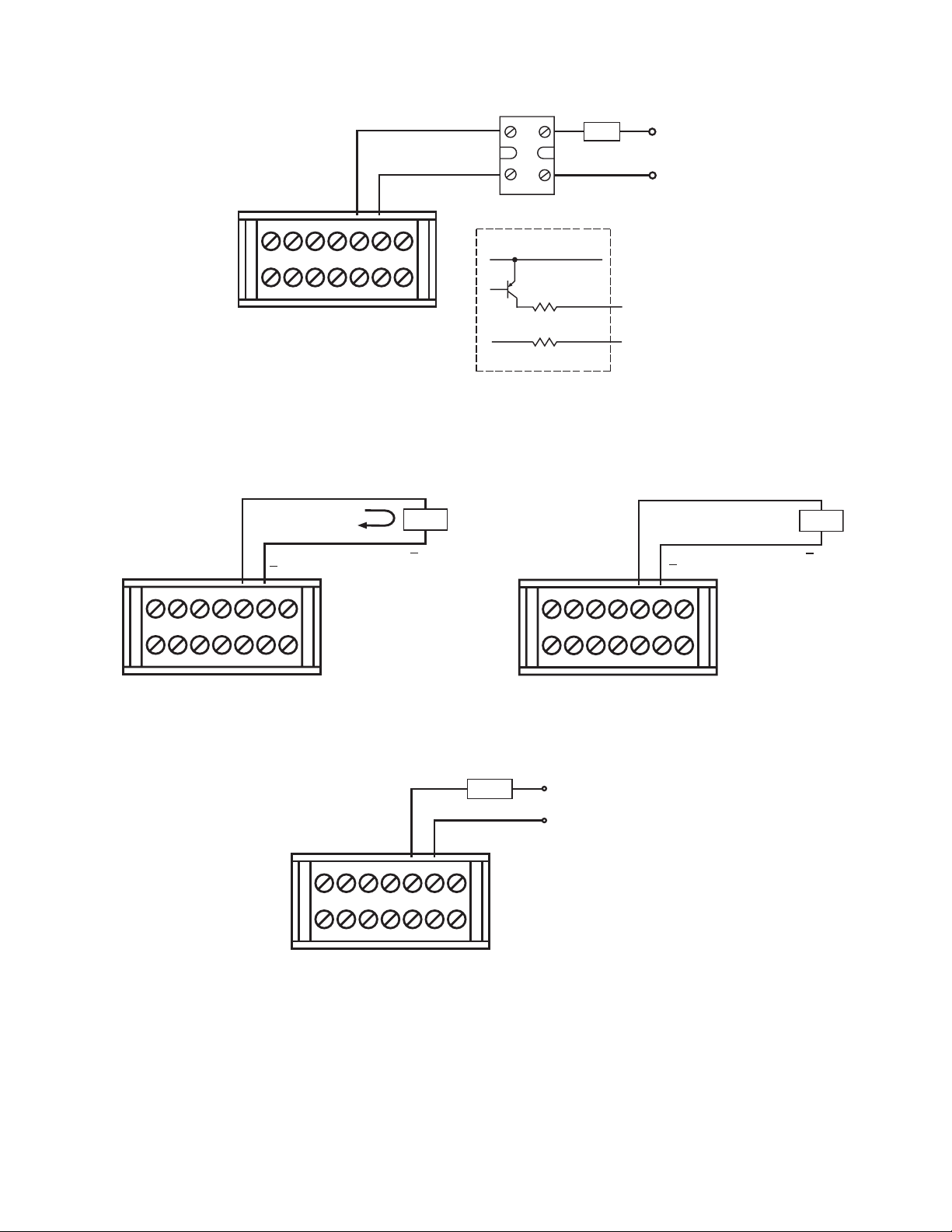
Figure 2.14 Output 1 Wiring
12
34
5
8910
11
67
121314
Relay or Triac (SSR) Output to Drive Contactor
120V /240V
Main Supply
No Fuse
Breaker
Three
Phase
Heater
Power
Three Phase Delta
Heater Load
12
34
5
8910
11
67
121314
Contactor
30 mA/5V
+
+
Pulsed Voltage
_
+
5
12
34
67
SSR
+
_
Internal circuit
5V
Load
120V /240V
Main Supply
12
8910
8910
11
121314
33
33
0V
Pulsed Voltage to Drive SSR
0 - 20mA,
4 - 20mA
Load
+
5
34
67
Maximum Load
500 ohms
12
11
121314
Linear Current
8910
+
5
6
0 - 1V, 0 - 5V
1 - 5V, 0 - 10V
+
5
34
11
12
67
13
Linear Voltage
Load
Minimum Load
10K ohms
14
Max. 1A/240V
Load
Triac
12
8910
34
11
67
121314
5
Triac (SSR) Output Direct Drive
23
120V /240V
Main Supply
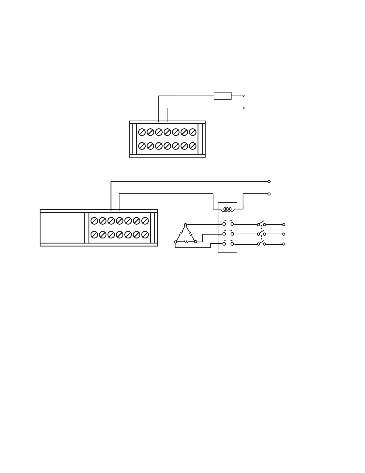
Page 28
2-12 Output 2 Wiring
Figure 2.15 Output 2 Wiring
12
34
Max. 2A
Resistive
Load
5
67
120V/240V
Main Supply
12
8910
30 mA/5 V
34
11
Pulsed
Voltage
12
5
67
121314
+
34
8910
11
121314
Relay Output Direct Drive
120V /240V
Main Supply
Three Phase Delta
Heater Load
Contactor
No Fuse
Breaker
Relay or Triac (SSR) Output to Drive Contactor
SSR
+
_
_
Internal Circuit
5
67
5V
Load
120V /240V
Main Supply
Three
Phase
Heater
Power
8910
13
11
12
14
33
33
+
3
4
0V
Pulsed Voltage to Drive SSR
24
Page 29
+
+
Minimum Load
Figure 2.16 Alarm Wiring
r
0 - 20mA,
4 - 20mA
+
12
8910
34
11
121314
67
5
Linear Current
2-13 Alarm 1 Wiring
Load
Maximum Load
500 ohms
Max. 1A /240 V
Triac
34
12
8910
11
Triac (SSR) Output Direct Drive
Load
5
67
121314
12
8910
120V /240V
Main Supply
0 - 1V, 0 - 5V
1 - 5V, 0 - 10V
+
5
34
67
13
11
12
14
Linear Voltage
Load
10 K ohms
1K
5V
0V
12
8910
7
14
5
34
+
67
11
121314
34
12
8910
11
Internal Circuit
5
67
121314
5V DC
Relay
Max. 2A
Resistive
Load
Single Phase Load
5V DC Relay
Three Phase
Delta
Heater
Load
120V/240V
Main Supply
Contactor
120V /240V
Mains Supply
Three
Phase
Heate
Power
No Fuse
Breaker
Three Phase Load
25
Page 30
2-14 Alarm 2 Wiring
Figure 2.17 Alarm 2 Wiring
r
12
8910
34
11
5
67
121314
Max. 2A
Resistive
Load
Relay Output
Direct Drive
120V/240V
MainSupply
120V/240V
MainsSupply
5
34
12
8910
11
121314
67
Three Phase
Delta
Heater
Load
Relay Output to DriveContactor
Contactor
Three
Phase
Heate
Power
No Fuse
Breaker
26
Page 31

Figure 2.18 RS-485 Wiring
2-15 RS-485
12
8910
12
8910
5
34
67
13
11
12
14
TX1
Twisted-PairWire
34
11
TX1
5
12
TX2
67
13
14
TX2
RS-485
RS-485 to RS-232
network adaptor
SNA10A or
SNA10B
RS-232
TX1
PC
TX2
12
8910
Max. 247 units can be linked
5
34
TX1
67
13
11
12
14
TX2
Terminator
220 ohms/0.5W
27
Page 32

2-16 RS-232
Figure 2.19 RS-232 Wiring
Figure 2.20 Location of Jumper J51/J52
ort
Figure 2.21 Configuration of RS-232 Cable
12
8910
34
11
5
67
121314
PC
COM
TX1TX2
9-pin
RS-232 port
CC94-1
NOTE: If the ETR-3400 is configured for RS-232 communication, the input 2 and EI (Event Input)ar
disconnected internally. The unit can no longer perform event input function (EIFN) and input 2 function.
When you insertaRS-232 module (CM94-2) to the connectorson CPU board (C250), the jumper
J51 and J5 must be modified as following: J52 must be shorted and J51 mustbecut and left open.
Location of jumper is shown in the following diagram.
Jumper
25J
15J
25U
1
15WS
PIDNO
432
55NC
45NC
1
If you use a conventional 9-pin RS-232 cable instead of CC94-1, the cable
must be modified according to the following circuit diagram.
ETR-3400
TX1
TX2
COM
9
10
14
TX1RD
TX2TD
COMGND
28
To DTE(PC)RS-232 P
1DCD
1
6
2
7
3
8
4
9
5
2RD
3TD
4DTR
5 GND
6DSR
7 RTS
8 CTS
Female DB-9
9RI
Display
Page 33

2-17 Analog Retransmission
Figure 2.22 Analog Retransmission Wiring
5
12
8910
34
11
67
121314
The total effectiveresistanceofserial
loads can't exceed500 ohms.
12
8910
34
11
+
Load
0-20mA,
4-20mA
Retransmit Current
5
67
121314
+
Load
1-5V,0-5V
0-10V
Retransmit Voltage
Load
++
Load
+
Indicators
PLC's
Recorders
Data loggers
Invertors etc.
The total effective resistance of parallel
loads should be greater than 10K Ohms.
Indicators
Load
+++
Load
PLC's
Recorders
Data loggers
Invertors etc.
29
Page 34

2-18 Programming Port
Don't attempt to make any connectionto these jumpers while the unitisoperating.
Figure 2.23 Programming Port Wiring
520A
See Figure 1.3 in Section 1-3 to find the programming port location.
Programmer
connector and
ATEconnector
inserted here
1
PIDNO
432
Programmer
P11A
Access hole
on the
bottom view
INPT1
Switch Unit
DMM
SW6400
HP 34401A
Calibrator
NOTE
The programming port is usedfor off-line automatic setup andtestingprocedures only.
30
Fluke5
Page 35

Chapter 3 Programming the Basic Function
This unit provides a useful function parameter “FUNC”, this is used to select the Function Complexity Level before
setup. If the Basic Mode (FUNC = BASC) is selected for a simple application, then the following functions are ignored and deleted from the full function menu:
RAMP, SP2, PB2, TI2, TD2, PL1, PL2, COMM, PROT, ADDR, BAUD, DATA, PARI, STOP, AOFN, AOLO, AOHI, IN2,
IN2U, DP2, IN2L, IN2H, EIFN, PVMD, FILT, SLEP, SPMD and SP2F.
Basic Mode Capabilities:
(1) Input 1: Thermocouple, RTD, Volt, mA
(2) Input 2: CT for heater break detection
(3) Output 1: Heating or Cooling ( Relay, SSR,
SSRD, Volt, mA )
(4) Output 2: Cooling ( Relay, SSR, SSRD, Volt, mA ),
DC Power supply.
(5) Alarm 1: Relay for Deviation, Deviation Band,
Process, Heater Break, Loop Break, Sensor
Break, Latch, Hold or Normal Alarm.
(6) Alarm 2: Relay for Deviation, Deviation Band,
Process, Heater Break, Loop Break, Sensor
Break, Latch, Hold or Normal Alarm.
(7) Dwell Timer
(8) Heater Break Alarm
(9) Loop Break Alarm
(10) Sensor Break Alarm
(11) Failure Transfer
(12) Bumpless Transfer
(13) PV1 Shift
(14) Programmable SP1 Range
(15) Heat-Cool control
(16) Hardware Lockout
(17) Self-Tune
(18) Auto-Tune
(19) ON-OFF, P, PD, PI, PID Control
(20) User Defined Menu (SEL)
(21) Manual Control
(22) Display Mode
(23) Reload Default Values
(24) Isolated DC Power Supply
(25) PV or SV Selection
If You don’t need:
(1) Second set point
(2) Second PID
(3) Event input
(4) Soft start (RAMP)
(5) Remote set point
(6) Complex process value
(7) Output power limit
(8) Digital communication
(9) Analog retransmission
(10) Power shut off (Sleep Mode)
(11) Digital filter
(12) Pump control
(13) Remote lockout
Then you can use Basic Mode
31
Page 36

3-1 Input 1
Figure 3.1 Conversion Curve for Linear Type Process Value
Press to enter Setup Mode. Press to select parameter. The upper display indicates the parameter
symbol, and the lower display indicates the selection or the value of parameter.
IN1: Selects the sensor type and signal type for Input 1.
Range: Thermocouple: J-TC, K-TC, T-TC, E-TC, B-TC, R-TC, S-TC, N-TC, L-TC
RTD: PT.DN, PT.JS
Linear: 4-20, 0-20, 0-1V, 0-5V, 1-5V, 0-10
Default: J-TC if F is selected, K-TC if C is selected.
IN1u: Selects the process unit for Input 1.
Range: C, F, PU ( process unit ) If the unit is neither C nor F, then selects PU.
Default: C or F.
DP1: Selects the location of the decimal point for most (not all) process related parameters.
Range: (For T/C and RTD) NO.DP, 1-DP
(For Linear) NO.DP, 1-DP, 2-DP, 3-DP
Default: 1-DP
IN1L: Selects the low scale value for the Linear type input 1.
T/C Hidden if: or RTD type is selected for IN1.
IN1H: Selects the high scale value for the Linear type input 1.
T/C Hidden if: or RTD type is selected for IN1.
How to use IN1L and IN1H :
If 4 - 20mA is selected for IN1,let SL specifies the input signal low (i.e. 4mA), SH specifies the input signal high (i.e.
20mA), S specifies the current input signal value, the conversion curve of the process value is shown as follows:
process value
IN1H
PV1
IN1L
SL SHS
S - SL
Formula: PV1 = IN1L + ( IN1H IN1L )
SH - SL
Example: A 4-20mA current loop pressure transducer with range 0 - 15 kg/cm2 is connected to input 1,
then perform the following setup :
IN1 = 4 - 20 IN1L = 0.0
IN1U = PU IN1H = 15.0
DP1 = 1-DP
Of course, you may select another value for DP1 to alter the resolution.
input signal
32
Page 37

3-2 Out1 & Out2 Types
o1ty: Selects the signal type for Output 1.
The selection should be consistent with the output 1 module installed.
The available output 1 signal types are :
RELY : Mechanical relay
SSRD : Pulsed voltage output to drive SSR
SSR : Isolated zero-switching solid state relay
4 - 20 : 4 - 20mA linear current output
0 - 20 : 0 - 20mA linear current output
0 - 1V : 0 - 1V linear voltage output
0 - 5V : 0 - 5V linear voltage output
1 - 5V : 1 - 5V linear voltage output
0 - 10V : 0 - 10V linear voltage output
o2ty: Selects the signal type for Output 2
The selection should be consistent with the output 2 module installed.
The available output 2 signal types are the same as for O1TY
The range for linear current or voltage may not be very accurate. For 0% output, the value for 4 - 20mA may be
3.8mA to 4mA; while for 100% output, the value for 4 - 20mA may be 20mA to 21mA. However, this deviation will
not degrade the control performance at all.
3-3 Rearrange User Menu
The ETR-3400 has the flexibility to provide selection of User Parameters which are most significant to your process. These parameters are placed in front of the display sequence.
sel1: Selects the most significant parameter for view and change.
sel2: Selects the 2nd significant parameter for view and change.
sel3: Selects the 3rd significant parameter for view and change.
sel4: Selects the 4th significant parameter for view and change.
sel5: Selects the 5th significant parameter for view and change.
Range: NONE, TIME, A1.SP, A1.DV, A2.SP, A2.DV, RAMP, OFST, REFC, SHIF, PB1, TI1, TD1, C.PB, SP2, PB2, TI2, TD2
When using the up-down key to select the parameters, you may not obtain all of the above parameters. The number of visible parameters is dependent on the setup condition. The hidden parameters for the specific application
are also deleted from the SEL selection.
Example:
A1FN selects TIMR
A2FN selects DE.HI
PB1 = 10
TI1 = 0
SEL1 selects TIME
SEL2 selects A2.DV
SEL3 selects OFST
SEL4 selects PB1
SEL5 selects NONE
Now, the upper display scrolling becomes:
PV
33
Page 38

3-4 Display SV Instead of PV
SP1+O1HY/2
SP1
O1HY
Figure 3.2 Heat Only ON-OFF Control
In certain applications where set point value (SV) is more important than process value (PV) for the user, the parameter disf (display format) then can be used to achieve this purpose.
Press keys to enter setup menu set, then press several times until disf appears on the display. If
you need the process value to be displayed, then select by using or key for DISF, If you need set point
value instead of process value to be displayed, then select S for DISF. Also refer to the flow chart in Section 1-5
to see the location of DISF.
3-5 Heat Only Control
Heat Only ON-OFF Control: Select REVR for OUT1, Set PB1 to 0, SP1 is used to adjust set point value, O1HY is
used to adjust dead band for ON-OFF control, TIME is used to adjust the dwell timer (enabled by selecting TIMR
for A1FN or A2FN). The output 1 hysteresis (O1HY) is enabled in case of PB1 = 0. The heat only on-off control
function is shown in the following diagram:
PV
SP1
O1HY/2
OUT1 Action
ON
OFF
The ON-OFF control may still introduce excessive process oscillation if hysteresis achieve a is minimized to the
smallest. If ON-OFF control is set (i.e. PB1 = 0), TI1, TD1, CYC1, OFST, CPB and PL1 will be hidden and have no
function to the system. The manual mode, auto-tuning, self-tuning and bumpless transfer will be disabled too.
Heat only P (or PD) Control: Select REVR for OUT1, set TI1 to 0, SP1
is used to adjust set point value, TIME is used to adjust the dwell timer
(enabled by selecting TIMR for A1FN or A2FN). OFST been enabled in
case of TI1 = 0 is used to adjust the control offset (manual reset). Adjust
CYC1 according to the output 1 type (O1TY).Generally, CYC1= 0.5 ~ 2
sec for SSRD and SSR, CYC1=10 ~ 20 sec for relay output .CYC1 is
ignored if linear output is selected for O1TY. O1HY is hidden if PB1 is
not equal to 0.
OFDT Function: OFST is measured by % with range 0 - 100.0%. In the steady state (i.e. process has been stabilized) if the process value is lower than the set point by a definite value, say 5˚C, while 20˚C is used for PB1, that is
lower 25%, then increase OFST 25%, and vice versa. After adjusting OFST value, the process value will be varied
and eventually, coincide with set point. Using the P control (TI1 set to 0), the auto-tuning and self-tuning are disabled. Refer to section 3-21 “ manual tuning “ for the adjustment of PB1 and TD1. Manual reset (adjust OFST) is
not practical because the load may change from time to time and often need to adjust OFST repeatedly. The PID
control can avoid this situation.
Dead band=
Time
Time
Setup ON-OFF:
OUT1 = reyr
PB1 = 0
Adjust: SP1, O1HY, TIME (if enabled)
Setup P:
OUT1 = reyr
Tl1 = 0
CYC1 (if RELAY, SSRD or SSR is
selected for O1TY
Adjust: SP1, OFST, TIME (if enabled)
PB1 (≠0), TD1
34
Page 39

Heat Only PID Control: Selecting REVR for OUT1, SP1 is used to ad-
SP1+O1HY/
SP1
O1HY
Time
Figure 3.3 Cool Only ON-OFF Control
just set point value. TIME is used to adjust the dwell timer (enabled by
selecting TIMR for A1FN or A2FN). PB1 and TI1 should not be zero.
Adjust CYC1 according to the output 1 type (O1TY). Generally, CYC1
= 0.5 ~ 2 sec for SSRD and SSR, CYC1 = 10 ~ 20 sec for relay output.
CYC1 is ignored if linear output is selected for O1TY.
In most cases the self-tuning can be used to substitute the autotuning. See section 3-19.
Section 3-19: If self-tuning is not used (select NONE for SELF), then
use auto-tuning for the new process, or set PB1, TI1 and TD1 with
historical values. See section 3-20 for auto-tuning operation. If the
control result is still unsatisfactory, then use manual tuning to improve
the control . See section 3-21 for manual tuning. ETR-3400 contains
a very clever PID and Fuzzy algorithm to acheive a very small over-
Setup PID:
OUT1 = reyr
O1TY
CYC1 (if RELAY, SSRD or SSR is selected for O1TY)
SELF = NONE or YES
Adjust: SP1, TIME ( if enabled ),
PB1 (= 0), TI1 (= 0), Td1.
Auto Tuning: Used for new process.
during initial tuning
Self Tuning: Used for a process any
time
Manual Tuning: May be used if selftuning and auto-tuning are inadequate.
shoot and very quick response to the process if it is properly tuned.
3-6 Cool Only Control
ON-OFF control, P (PD) control and PID control can be used for cool control. Set OUT1 to DIRT (direct action). The
other functions for cool only ON-OFF control, cool only P (PD) control and cool only PID control are same as
descriptions in section 3-5 for heat only control except that the output variable (and action) for the cool control is
inverse to the heat control, such as the following diagram shows:
PV
2
SP1
O1HY/2
OUT1 Action
ON
OFF
Setup ON-OFF:
OUT1 = dirt
Dead band =
Time
35
Page 40

3-7 Heat Cool Control
: Has no influence
: Adjust to meet process requirements
Table 3.1 Heat-Cool Control Setup
Control Modes
Heat
Uses
Cool
Uses
Setup Values
OUT1 OUT2 O1HY OFST
PB1 TI1 TD1
CPB
A2FN A2MD A2HY
Heat :ON-OFF
Cool : ON-OFF
Heat :ON-OFF
Cool :P(PD)
Heat :ON-OFF
Cool : PID
Heat :P(PD)
Cool : ON-OFF
Heat : PID
Cool : ON-OFF
Heat : PID
Cool : PID
OUT1
OUT2
OUT2
OUT1
OUT1
OUT1
OUT2
OUT1
OUT1
OUT2
OUT2
OUT2
REVR
DIRT
DIRT
REVR
REVR
REVR
=AL2
=AL2
=AL2
=AL2
=AL2
COOL
DE.HI
or
PV1.H
DE.LO
or
PV1.L
DE.LO
or
PV1.L
DE.HI
or
PV1.H
DE.HI
or
PV1.H
NORM
NORM
NORM
NORM
NORM
=0
DB
=0
=0
=0
=0
=0
=0
=0
=0
=0
=0
The Heat-Cool Control can use one of 6 combinations of control modes. Setup of parameters for each control
mode are shown in the following table.
NOTE: The ON-OFF control may result in excessive overshoot and undershoot problems in the process. The P (or
PD) control will result in a deviation process value from the set point. It is recommended to use PID control for the
Heat-Cool control to produce a stable and zero offset process value.
Other Setup Required: O1TY, CYC1, O2TY, CYC2, A2SP, A2DV
O1TY & O2TY are set in accordance with the types of OUT1 & OUT2 installed. CYC1 & CYC2 are selected according to the output 1 type (O1TY) & output 2 type (O2TY).
Generally, selects 0.5 ~ 2 sec. for CYC1, if SSRD or SSR is used for O1TY; 10 ~ 20 sec. if relay is used for O1TY,
and CYC1 is ignored if linear output is used. Similar condition is applied for CYC2 selection.
If OUT2 is configured for ON-OFF control (by selecting = AL2), the OUT2 acts as alarm output, and the process
alarm as well as deviation alarm (see section 3-9 & 3-10) can be used. Adjust A2SP to change set point if process
alarm is used, and adjust SP1 (with preset A2DV) to change set point if deviation alarm is used.
Examples:
Heat PID+Cool ON-OFF: Set OUT1= REVR, OUT2 = AL2, A2FN= PV1.H, A2MD=NORM, A2HY=0.1, PB1=0,
TI1=0,TD1=0, and set appropriate values for O1TY and CYC1.
Heat PID+Cool PID: Set OUT1=REVR, OUT2=COOL, CPB=100, DB=-4.0, PB1=0, TI1=0, TD1=0 and set appropriate values for O1TY, CYC1, O2TY, CYC2.
If you have no idea about a new process, then use self-tuning program to optimize the PID values by selecting
YES for SELF to enable the self-tuning program. See section 3-19 for self-tuning description. You can use the
auto-tuning program for the new process or directly set the appropriate values for PB1, TI1 & TD1 according to
the historical records for the repeated systems. If the control behavior is still inadequate, then use manual tuning
to improve the control. See section 3-21 for manual tuning.
36
Page 41

CPB Programming: The cooling proportional band is measured by % of PB with range 1~255. Initially set 100% for
ON
OF
A1
Timer starts
Figure 3.4 Dwell Timer Function
CPB and examine the cooling effect. If cooling action should be enhanced then decrease CPB, if cooling action
is too strong then increase CPB. The value of CPB is related to PB and its value remains unchanged throughout
the self-tuning and auto-tuning procedures.
Adjustment of CPB is related to the cooling media used. For air used as cooling media, adjust CPB at 100(%). For
oil used as cooling media, adjust CPB at 125(%). For water used as cooling media, adjust CPB at 250(%).
DB Programming: Adjustment of DB is dependent on the system requirements. If more positive value of DB
(greater dead band) is used, an unwanted cooling action can be avoided but an excessive overshoot over the set
point will occur. If more negative value of DB (greater overlap) is used, an excessive overshoot over the set point
can be minimized but an unwanted cooling action will occur. It is adjustable in the range -36.0% to 36.0 % of PB1
(or PB2 if PB2 is selected). A negative DB value shows an overlap area over which both outputs are active. A positive DB value shows a dead band area over which neither output is active.
3-8 Dwell Timer
Alarm 1 or alarm 2 can be configured as dwell timers by selecting TIMR for A1FN or A2FN, but not both, otherwise
Er07 will appear. As the dwell timer is configured, the parameter TIME is used for dwell time adjustment. The dwell
time is measured in minutes ranging from 0 to 6553.5 minutes. Once the process reaches the set point, the dwell
timer starts to count from zero until time out. The timer relay will remain unchanged until time out.
Same case is for alarm 2.
Example:
Set A1FN=TIMR or A2FN=TIMR but not both.
Adjust TIME in minutes
A1MD ( if A1FN=TIMR ) or A2MD ( if A2FN=TIMR ) is ignored in this case.
If alarm 1 is selected for dwell timer, an external 5V DC relay is required to drive AC load.
If alarm 1 is configured as dwell timer, A1SP, A1DV, A1HY and A1MD are hidden.
SP1
or A2
F
PV
TIME
Time
Time
Time
37
Page 42

3-9 Process Alarms
5
195
Figure 3.5 Normal Process Alarm
A
A1MD = NORM A1FN=PV1.H
There are at most two independent alarms available by adjusting OUT2. If AL2 is selected for OUT2, then OUT2 will
perform alarm 2 function. Now A2FN can’t be selected with NONE, otherwise Er06 will be displayed. A process
alarm sets an absolute trigger level (or temperature). When the process (could be PV1, PV 2 or PV1-PV2) exceeds
that absolute trigger level an alarm occurs. A process alarm is independent from set point. Adjust A1FN (Alarm 1
function) in setup menu. One of 8 functions can be selected for process alarm. These are: PV1.H, PV1.L, PV2.H,
PV2.L, P1.2.H, P1.2.L, D1.2.H, D1.2.L. When the PV1.H or PV1.L is selected the alarm examines the PV1 value.
When the PV2.H or PV2.L is selected the alarm examines the PV2 value. When the P1.2.H or P1.2.L is selected
the alarm occurs if the PV1 or PV2 value exceed the trigger level. When the D1.2.H or D1.2.L is selected the alarm
occurs if the PV1-PV2 (difference) value exceeds the trigger level. The trigger level is determined by A1SP (Alarm
1 set point) and A1HY ( Alarm 1 hysteresis value ) in User Menu for alarm 1. The hysteresis value is introduced to
avoid interference action of alarm in a noisy environment. Normally A1HY can be set with a minimum (0.1) value.
A1DV and/or A2DV are hidden if alarm 1 and/or alarm 2 are set with process alarm.
Normal Alarm: A1MD = NORM
When a normal alarm is selected, the alarm output is de-energized in the non-alarm condition and energized in an
alarm condition.
Latching Alarm: A1MD = LTCH
If a latching alarm is selected, once the alarm output is energized, it will remain unchanged even if the alarm condition is cleared. The latching alarms are disabled when the power is shut off or if event input is applied with proper
selection of EIFN.
Holding Alarm: A1MD = HOLD
A holding alarm prevents an alarm from power up. The alarm is enabled only when the process reaches the set
point value (may be SP1or SP2, See section 4-1 event input). Afterwards, the alarm performs same function as
normal alarm.
Latching / Holding Alarm: A1MD = LT.HO
A latching / holding alarm performs both holding and latching function.
Examples:
A1SP = 200 A1HY = 10.0
A1MD = NORM A1FN = PV1.H
8 Types of Process Alarms:
PV1.H, PV1.L, PV2.H, PV2.L, P1.2.H, P1.2.L, D1.2.H, D1.2.L
Process Alarm 1 Process Alarm 2
Setup: A1FN, A1MD Setup: OUT2, A2FN, A2MD
Adjust: A1SP, A1HY Adjust: A2SP, A2HY
Trigger level = A1SPA1/2 A1HY Trigger level = A2SPA1/2 A2HY
Reset Latching Alarm
1. Power off
2. Apply Event input in accordance with proper selection of EIFN
Process proceeds
205
195
1SP = 200 A1HY=10.0
205
195
ON
205 205 20
195 195
OFF
38
Page 43

Figure 3.6 Latching Process Alarm
A1MD=LTCH A1FN=PV1.H
Process proceeds
210
5
195
Figure 3.7 Holding Process Alarm
A1MD=HOLD A1FN=PV1.L
0
5
Figure 3.8 Latching/Holding Process Alarm
A1MD=LT.HO A1FN=PV1.L
205
195
205
195
ON
205
195
A1SP=200 A1HY=10.0
Process proceeds
205
195
205
195
210210 210
205
195 195 195
205 205
A1SP=200 A1HY = 10.0 SP1 = 210
ON
205
195
205
195
OFF
20
Process proceeds
205
195
205
195
210 210 210 21
205
195 195 195 195
205 205 20
ON
A1SP=200 A1HY=10.0 SP1 = 210
Although the above descriptions are based on alarm 1, the same conditions can be applied to alarm 2.
39
Page 44

3-10 Deviation Alarm
Process proceeds
OUT2 can be configured as alarm 2 by selecting=AL2. If OUT2 selects=AL2, then output 2 will perform alarm 2
function. Now A2FN can’t be selected with NONE, otherwise Er06 will appear.
A deviation alarm alerts the user when the process deviates too far from set point. The user can enter a positive
or negative deviation value (A1DV, A2DV) for alarm 1 and alarm 2. A hysteresis value (A1HY or A2HY) can be selected to avoid interference problem of alarm in a noisy environment. Normally, A1HY and A2HY can be set with a
minimum (0.1) value.
Trigger levels of alarm are moving with set point.
For alarm 1, Trigger levels=SP1+A1DV 1/2 A1HY.
For alarm 2, Trigger levels=SP1+A2DV 1/2 A2HY.
A1SP and/or A2SP are hidden if alarm 1 and/or alarm 2 are set with deviation alarm. One of 4 kinds of alarm modes
can be selected for alarm 1 and alarm 2. These are: Normal alarm, Latching alarm, Holding alarm and Latching/
Holding alarm. See Section 3-9 for descriptions of these alarm modes.
2 Types of Deviation Alarms: DE.HI, DE.LO
Deviation Alarm 1 Deviation Alarm 2:
Setup: A1FN, A1MD Setup: OUT2, A2FN, A2MD
Adjust: SP1, A1DV, A1HY Adjust: SP1, A2DV, A2HY
Trigger levels = SP1+A1DV 1/2A1HY Trigger levels = SP1+A2DV 1/2A2HY
Figure 3.9
Normal Deviation
Alarm
Figure 3.10
Latching Deviation
Alarm
Figure 3.11
Holding Deviation
Alarm
112
108
100
A1FN=DE.HI, A1MD=NORM, SP1=100, A1DV=10,A1HY=4
Process proceeds
112
108
100
A1FN=DE.HI, A1MD=LTCH, SP1 = 100, A1DV=10, A1HY=4
Process proceeds
100
92
88
A1HY=DE.LO, A1MD = HOLD, SP1 = 100, A1DV= -10, A1HY=4
100
92
88
112
108
100
112
108
100
ON
ON
100
92
88
112
108
100
112
108
100
100
92
88
ON
112
108
100
112
108
100
OFF
100
92
88
100
92
88
OFF
112
108
100
112
108
100
100
92
88
Figure 3.12
Latching/Holding
Deviation Alarm
Process proceeds
100
92
88
A1HY= DE.LO, A1MD=LT. HO, SP1 = 100, A1DV= -10, A1HY=4
100
92
88
40
100
92
88
100
92
88
ON
92
88
100100
92
88
100
92
88
Page 45

3-11 Deviation Band Alarm
A deviation band alarm presets two reference levels relative to set point. Two types of deviation band alarm can be
configured for alarm 1 and alarm 2. These are deviation band high alarm (A1FN or A2FN select DB.HI) and deviation band low alarm (A1FN or A2FN select DB.LO). If alarm 2 is required, then select =AL2 for OUT2. Now A2FN
can’t be selected with NONE, otherwise er06 will appear. A1SP and A1HY are hidden if alarm 1 is selected with
deviation band alarm. Similarly, A2SP and A2HY are hidden if alarm 2 is selected with deviation band alarm.
Trigger levels of the deviation band alarms will move with the set point.
For alarm 1, the trigger level=SP1 A1DV.
For alarm 2, the trigger level=SP1 A2DV.
One of 4 kinds of alarm modes can be selected for alarm 1 and alarm 2. These are: Normal alarm, Latching alarm,
Holding alarm and Latching/Holding alarm.
See Section 3-9 for descriptions of these alarm modes.
Process proceeds
Figure 3.13
Normal Deviation
Band Alarm
Figure 3.14
Latching Deviation
Band Alarm
Figure 3.15
Holding Deviation
Band Alarm
105
100
ON
A1FN=DB.HI, A1MD=NORM, SP1=100, A1DV=5
A1FN=DB.LO, A1MD=LTCH, SP1 = 100, A1DV=5
105
100
95
105
100
95
95
OFF
ON
105
100
95
Process proceeds
105
100
95
Process proceeds
105
100
95
105
100
95
105
100
95
105
100
95
ON
ON
105
100
95
105
100
95
105
100
95
OFF
OFF
105
100
95
105
100
95
ON
105
100
95
105
100
95
105
100
95
Figure 3.16
Latching/Holding
Deviation Band Alarm
A1FN=DB.HI, A1MD=HOLD,SP1 = 100, A1DV=5
Process proceeds
105105 105 105105 105
100100 100 100 100 100
95 95 95 95 95 95
A1FN=DB.HI, A1MD=LT.HO, SP1 = 100, A1DV=5
41
ON
Page 46

3-12 Heater Break Alarm
10
40
Figure 3.17 Heater Break Alarm
A current transformer (part No. CT94-1) should be installed to detect the heater current if a heater break alarm is
required. The CT signal is sent to input 2, and the PV2 will indicate the heater current in 0.1 Amp. resolution.
The range of the current transformer is 0 to 50.0 Amp.
For more detailed descriptions about heater current monitoring, please see Section 3-25.
Example:
A furnace uses two 2KW heaters connected in parallel to warm up the process.
The line voltage is 220V and the rating current for each heater is 9.09A. If we want to detect any one heater break,
set A1SP=13.0A, A1HY=0.1 A1FN=PV2.L, A1MD=NORM, then
Heater Break Alarm 1 Heater Break Alarm 2
Setup: IN2 = CT Setup: IN2 = CT
A1FN = PV2.L A2FN = PV2.L
A1MD = NORM A2MD = NORM
A1HY = 0.1 A2HY = 0.1
Adjust: A1SP Adjust: A2SP
Trigger levels: A1SP 1/2 A1HY Trigger levels: A2SP 1/2 A2HY
Limitations:
1. Linear output can’t use heater break alarm.
2. CYC1 should use 1 second or longer to detect heater current reliably.
No heater breaks 1 heater breaks 2 heaters break
20 30
0
Alarm !
20 30
40
A
50
10
A
0
50
40
10
20 30
0
Alarm!
A
50
42
Page 47

3-13 Loop Break Alarm
A1FN selects LB if alarm 1 is required to act as a loop break alarm. Similarly, if alarm 2 is required to act as a loop
break alarm, then set OUT2 withAL2 and A2FN with LB.
TIME, A1SP, A1DV and A1HY are hidden if alarm 1 is configured as a loop break alarm. Similarly, TIME, A2SP, A2DV
and A2HY are hidden if alarm 2 is configured as a loop break alarm.
One of 4 kinds of alarm modes can be selected for alarm 1 and alarm 2. These are : Normal alarm, Latching alarm,
Holding alarm and Latching/Holding alarm. However, the Holding mode and Latching/Holding mode are not recommended to be chosen for loop break alarm since loop break alarm will not perform holding function even if it is
set with holding or latching/holding mode. See Section 3-9 for the descriptions of these alarm modes.
Loop Break Conditions are detected during a time interval of 2TI1 (double of integral time, but 120 seconds maximum). Hence the loop break alarm doesn’t respond quickly as it occurs. If the process value doesn’t increase (or
decrease) while the control variable MV1 has reached to its maximum (or minimum) value within the detecting time
interval, a loop break alarm ( f configured) will be actuated.
Loop Break Alarm 1 Loop Break Alarm 2
Setup: A1FN = LB Setup: OUT2 = =AL2
A1MD = NORM, LTCH A2FN = LB
A2MD = NORM, LTCH
Figure 3.18 Loop Break Sources
Heater
Process
Switching
Device
Controller
Loop Break Sources: Sensor, Controller, Heater, Switching Device
Loop Break Alarm (if configured) occurs when any following condition happens:
1. Input sensor is disconnected (or broken).
2. Input sensor is shorted.
3. Input sensor is defective.
4. Input sensor is installed outside (isolated from) the process.
5. Controller fails (A-D converter damaged).
6. Heater (or generally, chiller, valve, pump, motor etc.) breaks or fails or uninstalled.
7. Switching device (used to drive heater) is open or shorted.
Sensor
43
Page 48

3-14 Sensor Break Alarm
SP
IN1H (or sensor range high)
IN1L (or sensor range low)
Figure 3.19 SP1 Range
Alarm 1 or alarm 2 can be configured as sensor break alarm by selecting SENB for A1FN or A2FN. If alarm 2 is
required for sensor break alarm, then OUT2 should be selected with = AL2.
The sensor break alarm is activated as soon as failure mode occurs. Refer to Section 3-17 for failure mode conditions. Note that A-D Failure also creates a sensor break alarm. TIME,A1SP, A1DV, and A1HY are hidden if alarm 1
is configured as a sensor break alarm. Similarly, TIME, A2SP, A2DV and A2HY are hidden if alarm 2 is configured
as a sensor break alarm.
One of 4 kinds of alarm modes can be selected for sensor break alarm. These are: Normal alarm, Latching alarm,
Holding alarm and Latching/Holding alarm. However, the Holding alarm and Latching/Holding alarm are not recommended to be chosen for sensor break alarm since sensor break alarm will not perform holding function even if
it is set with holding or latching/holding mode. See Section 3-9 for the descriptions of these alarm modes.
Sensor Break Alarm 1 Sensor Break Alarm 2
Setup: A1FN=SENB Setup: OUT2= =AL2
A1MD=NORM, LTCH A2FN=SENB
Hidden: TIME, A1SP, A1DV A1HY A2MD=NORM, LTCH
Hidden: TIME , A2SP, A2DV, A2HY
3-15 SP1 Range
SP1L ( SP1 low limit value ) and SP1H ( SP1 high limit value ) in setup menu are used to confine the adjustment
range of SP1.
Setup: SP1L, SP1H
Example: A freezer is working in its normal temperature range -10˚F to -15˚F.
In order to avoid an abnormal set point, SP1L and SP1H are set with the following values:
SP1L = -15˚F SP1H = -10˚F
Now SP1 can only be adjusted within the range from -10˚F to -15˚F.
SP1H
1
SP1L
44
Page 49

3-16 PV Shift
r
35
dif
SHIF
Supply more heat
Figure 3.20 PV1 Shift Application
In certain applications it is desirable to shift the controller display value from its actual value. This can be easily
accomplished by using the PV1 shift.
Press the “scroll” key until the control reaches the parameter SHIF. The value you adjust here, either positive or
negative, will be added to the actual value. The SHIF function will PV1 only.
Here is an example. A process is equipped with a heater, a sensor and a subject to be warmed up. Due to the
design and position of the components in the system, the sensor could not be placed any closer to the part. Thermal gradient (different temperature) is common and necessary to an extent in any thermal system for heat to be
transferred from one point to another. If the difference between the sensor and the subject is 35˚F, and the desired
temperature at the subject to be heated is 200˚F, the controlling value or the temperature at the sensor should be
235˚F. You should input -35˚F as to subtract 35 F from the actual process display. This in turn will cause the controller to energize the load and bring the process display up to the set point
Heat
Transfer
165 F 165F 200F
F F F
°
F temperature
ferenceis observed
=0
Adjust SHIF
SHIF= -35
Heat
Transfer
° F
Displayis stable
SHIF=-35 F
PV=SV
tcejbuStcejbuStcejbuS
etaeHretaeHretaeH
Heat
Transfer
F532F002F002
rosneSrosneSrosneS
°
45
Page 50

3-17 Failure Transfer
The controller will enter failure mode as one of the following conditions occurs:
1. SB1E occurs (due to the input 1 sensor break or input 1 current below 1mA if 4-20 mA is selected or input 1
voltage below 0.25V if 1-5 V is selected) if PV1, P1-2 or P2-1 is selected for PVMD or PV1 is selected for SPMD.
2. SB2E occurs (due to the input 2 sensor break or input 2 current below 1mA if 4-20 mA is selected or input 2
voltage below 0.25V if 1-5 V is selected) if PV2, P1-2 or P2-1 is selected for PVMD or PV2 is selected for SPMD.
3. ADER occurs due to the A-D converter of the controller fails.
Failure Mode Occurs as:
1. SB1E
2. SB2E
3. ADER
Failure Transfer of outout 1 and output 2 occurs as: Failure Transfer Setup:
1. Power start (within 2.5 seconds) 1. O1FT
2. Failure mode is activated 2. O2FT
3. Manual mode is activated 3. A1FT
4. Calibration mode is activated 4. A2FT
Failure Transfer of alarm 1 and alarm 2 occurs as:
1. Failure mode is activated
The output 1 and output 2 will perform the failure transfer function as one of the following conditions occurs:
1. During power starts (within 2.5 seconds).
2. The controller enters the failure mode.
3. The controller enters the manual mode.
4. The controller enters the calibration mode.
Output 1 Failure Transfer, if activated, will perform:
1. If output 1 is configured as proportional control (PB1 = 0), and BPLS is selected for O1FT, then output 1 will
perform bumpless transfer. Thereafter the previous averaging value of MV1 will be used for controlling output 1.
2. If output 1 is configured as proportional control (PB1 = 0), and a value of 0 to 100.0% is set for O1FT, then output 1 will perform failure transfer. Thereafter the value of O1FT will be used for controlling output 1.
3. If output 1 is configured as ON-OFF control (PB1 = 0), then output 1 will be driven OFF if O1FN selects REVR
and be driven ON if O1FN selects DIRT.
Output 2 Failure Transfer, if activated, will perform:
1. If OUT2 selects COOL, and BPLS is selected for O2FT, then output 2 will perform bumpless transfer. Thereafter
the previous averaging value of MV2 will be used for controlling output 2.
2. If OUT2 selects COOL, and a value of 0 to 100.0 % is set for O2FT, then output 2 will perform failure transfer.
Thereafter the value of O1FT will be used for controlling output 2.
Alarm 1 Failure Transfer is activated as the controller enters failure mode. Thereafter the alarm 1 will transfer to
the ON or OFF state preset by A1FT.
Exception: If Loop Break (LB) alarm or sensor Break (SENB) alarm is configured for A1FN, the alarm 1 will be
switched to ON state independent of the setting of A1FT. If Dwell Timer (TIMR) is configured for A1FN, the alarm
1 will not perform failure transfer.
Alarm 2 Failure Transfer is activated as the controller enters failure mode. Thereafter the alarm 2 will transfer to
the ON or OFF state preset by A2FT.
Exception: If Loop Break (LB) alarm or sensor Break (SENB) alarm is configured for A2FN, the alarm 2 will be
switched to ON state independent of the setting of A2FT. If Dwell Timer (TIMR) is configured for A2FN, the alarm
2 will not perform failure transfer.
46
Page 51

3-18 Bumpless Transfer
Figure 3.21 Benefits of Bumpless Transfer
The bumpless transfer function is available for output 1 and output 2 (provided that OUT2 is configured as COOL).
Bumpless Transfer is enabled by selecting BPLS for O1FT and/or O2FT and activated as one of the following
cases occurs:
1. Power starts (within 2.5 seconds).
2. The controller enters the failure mode. See section 3-17 for failure mode descriptions.
3. The controller enters the manual mode. See section 3-23 for manual mode descriptions.
4. The controller enters the calibration mode. See chapter 6 for calibration mode descriptions.
As the bumpless transfer is activated, the controller will transfer to open-loop control and uses the previous averaging value of MV1 and MV2 to continue control.
Bumpless Transfer Setup:
1. O1FT = BPLS
2. O2FT = BPLS
Bumpless Transfer Occurs as:
1. Power Starts (within2.5 seconds)
2. Failure mode is activated
3. Manual mode is activated
4. Calibration mode is activated
Without
Bumpless
Transfer
Set point
PV
Power interrupted
Sensorbreak
Set point
Large
deviation
Time
With
Bumpless
Transfer
PV
Power interrupted
Sensor break
Load varies
Small
deviation
Time
Since the hardware and software need time to be initialized, the control is abnormal as the power is recovered and
results in a large disturbance to the process. During the sensor breaks, the process loses power.
After bumpless transfer is configured, the correct control variable is applied immediately as the power is recovered, the disturbance is small. During the sensor breaks, the controller continues to control by using its previous
value. If the load doesn’t change, the process will remain stable. Thereafter, once the load changes, the process
may run away. Therefore, Therefore, you should not rely on a bumpless transfer for a longer time. For fail safe
reason, an additional alarm should be used to announce the operator when the system fails. For example, a Sensor Break Alarm, if configured, will switch to failure state and announces the operator to use manual control or take
a proper security action when the system enters failure mode.
47
Page 52

3-19 Self Tuning
Self-tune Menu
-tuning
Default
SELF=NONE
The Self-tuning which is designed by using an innovative algorithm provides an
alternative option for tuning the controller. It is activated as soon as SELF is selected
with YES. When Self-tuning is working, the controller will change its working PID
values and compares the process behavior with previous cycle. If the new PID values
achieve a better control, then changing the next PID values in the same direction, otherwise, changing the next PID values in reverse direction. When an optimal condition
is obtained, the optimal PID values will be stored in PB1, TI1, TD1 or PB2, TI2, TD2
which is determined by Event Input conditions. See Section 4-1. When Self-tuning is
completed, the value of SELF returns to NONE.
When the Self-tuning is enabled, the control variables are tuned slowly so that the
disturbance to the process is less than auto-tuning. Usually, the Self-tuning algorithm
has a longer run time until ideal conditions are achieved compared to auto-tuning.
Exceptions: The Self-tuning will be disabled as soon as one of the following conditions occurs:
1. SELF is selected with NONE.
2. The controller is used for on-off control, that is PB=0.
3. The controller is used for manual reset, that is TI=0.
4. The controller is under loop break condition.
5. The controller is under failure mode (e.g. sensor break).
6. The controller is under manual control mode.
7. The controller is under sleep mode.
If the self-tuning is enabled, the auto-tuning can still be used any time. The self-tuning algorithm will otherwise run
until complete.
Selects
Disable Self
o
r
Enable Self-tuning
Benefits of Self-Tuning:
1. Unlike auto-tuning, Self-tuning will produce less disturbance to the process.
2.
3. Changing set point during Self-tuning is allowable. Hence, Self-tuning can be used for ramping set point control
Benefits of Self-Tune:
1. Less disturbance to the process.
2. Perform PID control during tuning period.
3. Available for ramping set point control and remote set point control.
Operation:
The parameter SELF is contained in setup menu. Refer to Section 1-5 to obtain SELF for initiating a self-tuning.
Unlike auto-tuning, Self-tuning doesn’t change control mode during tuning period. It always performs PID control.
as well as remote set point control.
48
Page 53

3-20 Auto Tuning
The auto-tuning process is performed at set point.
The process will oscillate around the set point during tuning process.
Set a set point to a lower value if overshooting beyond the normal setpoint is undesired.
The auto-tuning is applied in cases of :
• Initial setup for a new process
• The set point is changed substantially from the previous auto-tuning
Operation
1. The system has been installed normally.
2. Use the default values for PID before tuning.
The default values are : PB1=PB2=18.0 F TI1=TI2=100 sec, TD1=TD2=25.0 sec, Of course, you can use other
reasonable values for PID before tuning according to your previous experiences. But don’t use a zero value for
PB1 and TI1 or PB2 and TI2, otherwise, the auto-tuning program will be disabled.
3. Set the set point to a normal operating value or a lower value if overshooting beyond the normal process value
is likely to cause damage.
4. Press until A_t appears on the display.
5. Press
ning.
Applicable Conditions:
PB1=0, TI1=0 if PB1,TI1,TD1 assigned
PB2=0, TI2=0, if PB2, TI2, TD2 assigned
for at least 3 seconds. The upper display will begin to flash and the auto-tuning procedure is begin-
NOTE:
Any ramp function, remote set point or pump function, if used, will be disabled once auto-tuning is activated.
Procedures:
The auto-tuning can be applied either as the process is warming up (Cold Start) or as the process has been in
steady state (Warm Start). See Figure 3.22.
If the auto-tuning begins apart from the set point (Cold Start), the unit enters Warm-Up Cycle. As the process
reaches the set point value, the unit enters Waiting Cycle. The waiting cycle elapses a double integral time (Ti1
or TI2, dependent on the selection, see Section 4.1) then it enters a Learning Cycle. The double integral time is
introduced to allow the process to reach a stable state. Before learning cycle, the unit performs Pre-Tune function
with a PID control. While in learning cycle the unit performs Post-Tune function with an ON-OFF control. Learning
cycle is used to test the characteristics of the process. The data are measured and used to determine the optimal
PID values. At the end of the two successive ON-OFF cycles the PID values are obtained and automatically stored
in the nonvolatile memory.
After the auto-tuning procedures are completed, the process display will cease to flash and the unit revert to PID
control by using its new PID values.
During pre-tune stage the PID values will be modified if any unstable phenomenon which is caused by incorrect
PID values is detected. Without pre-tune stage, like other conventional controllers, the tuning result will be strongly
related to the time when the auto-tuning is applied. Hence different values will be obtained every time as autotuning is completed without pre-tune.
Pre-tune Function Advantage: Consistent tuning results can be obtained
49
Page 54

Auto-tuning
Set
Set
Figure 3.22 Auto-tuning Procedure
Begins
Auto-tuning
Complete
PV
Warm-up
Cycle
Waiting
Cycle
=2 Integral
Time
Point
Pre-tune Stage
PID Control
Auto-tuning
Begins
PV
Pre-tune Stage
Waiting
Cycle
=2 Integral
Time
Point
Pre-tune
Stage
Learning Cycle
Post-tune Stage
ON-OFF Control
Cold Start
Learning Cycle
Post-tune Stage
New PID Cycle
PID Control
Time
Auto-tuning
Complete
New PID Cycle
PID Control
ON-OFF Control
Warm Start
PID Control
Time
If the auto-tuning begins near the set point (warm start), the unit passes the warm-up cycle and enters the waiting
cycle. Afterward the procedures are the same and a new PID cycle begins.
ATer Auto Tuning Error
If auto-tuning fails an ATER message will appear on the upper display in cases of:
• If PB exceeds 9000 (9000˚PU, 900.0˚F or 500.0˚C).
• or if TI exceeds 1000 seconds.
• or if set point is changed during auto-tuning procedure.
• or if event input state is changed so that set point value is changed.
Solutions to ATer
1. Try auto-tuning once again.
2. Don’t change set point value during auto-tuning procedure.
3. Don’t change event input state during auto-tuning procedure.
4. Use manual tuning instead of auto-tuning. (See section 3-21).
5. Touch any key to reset ater message
50
Page 55

3-21 Manual Tuning
zero.
In certain applications (very few) using both self-tuning and auto-tuning to tune a process may be inadequate for
the control requirement, then you can try manual tuning.
Connect the controller to the process and perform the procedures according to Figure 3.23.
Figure 3.23 Manual Tuning Procedure
Use initial PID values
to control the process
No
Wait and Examine
the Process
Is
steady state
reached?
Yes
Does
the process
oscillate?
Yes
1 Flag
2PB1 PB1
Wait and Examine
the Process
No
steady state
reached ?
No
0 Flag
0.5PB1 PB1
Is
Wait and Examine
theProcess
No
No
steady state
reached?
the process
oscillate?
PB1 PBu
Oscillating period Tu
Load newPID values
1.7PBu PB1
0.3Tu TD1
Is
Yes
Does
Yes
Tu TI1
END
Yes
Does
the process
oscillate?
No
NOTE:
The finalPID valuescan't be
If PBu=0 then set PB1=1.
If Tu <1sec, then set TI1=1 sec.
No
Yes
Flag=0 ? Flag=1 ?
Yes
1.6PB1 PB1 0.8PB1 PB1
Yes
No
The above procedure may take a long time before reaching a new steady state since the P band was changed.
This is particularly true for a slow process. So the above manual tuning procedures will take from minutes to hours
to obtain optimal PID values.
51
Page 56

The PBu is called the Ultimate P Band and the period of oscillation Tu is called Ultimate Period the in the flow
Set
Time
Figure 3.24 Critical Steady
Ta ble 3.2PID Adjustment Guide
Figure 3.25 Effects of PID Adjustment
Time
Set
chart of Figure 3.23. When this occurs, the process is called in a critical steady state. Figure 3.24 shows a critical
steady state scenario.
PV
point
If the control performance by using above tuning is still unsatisfactory, the following troubleshooting techniques
can be attempted.
ADJUSTMENT SEQUENCE
(1) Proportional Band(P)
PB1 and/or PB2
(2) Integral Time(I)
TI1 and/or TI2
(3) Derivative Time(D)
TD1 and/or TD2
If PB=PBu
the process sustains to oscillate
Tu
SYMPTOMSOLUTION
Slow Response
High overshoot or
Oscillations
Slow Response
Instabilityor
Oscillations
Slow Response or
Oscillations
High Overshoot
Decrease PB1 or PB2
Increase PB1 or PB2
Decrease TI1 or TI2
Increase TI1 or TI2
Decrease TD1 or TD2
Increase TD1 or TD2
Figure 3.25 shows the effects of PID adjustment on process response
P action
PV
Perfect
point
PB too high
52
PB too low
Page 57

PV
Time
Set
Figure 3.25 (Continued) Effects of PID Adjustment
Set point
I action
TI too high
Perfect
TI too low
Time
D action
PV
point
TD too low
Perfect
TD too high
53
Page 58

3-22 Signal Conditioner DC Power Supply
e
Figure 3.26 DC Power Supply Applications
Three types of isolated DC power supply are available to supply an external transmitter or sensor. These are 20V
rated at 25mA, 12V rated at 40 mA and 5V rated at 80 mA. The DC power supply applications are shown in Figure
3.26.
Two-line Transmitter
+
+
12
34
67
5
8910
+
4-20mA
11
121314
Three-line
Transmitter
OUTCOM
IN
or sensor
+
Set
OUT2=
(DC Power Supply)
Bridge Typ
Sensor
+
12
8910
34
11
5
12
67
13
14
12
8910
34
11
5
67
121314
+ +
VormA
Caution: Don’t use the DC power supply beyond its rating current to avoid damage. Purchase a
correct voltage to suit your external devices. See ordering code in section 1-2.
54
Page 59

3-23 Manual Control
The manual control may be used for the following purposes:
1. To test the process characteristics in obtaining a step response as well as an impulse response for data needed
in tuning a controller.
2. To use manual control instead of a close loop control as the sensor fails or the controller’s A-D converter fails.
NOTE that a bumpless transfer can not be used for a long time. See section 3-18.
3. In certain applications it is desirable to supply a process with a constant demand.
Operation
Press until Hand (Hand Control) appears on the display. Press for 3 seconds then the upper display will
begin to flash and the lower display will show H___. The controller now enters the manual control mode. Pressing
the lower display will show C___ and H___ alternately where H___ indicates output 1 (or heating) control
variable value MV1 and C___ indicates output 2 (or cooling) control variable value MV2. Now you can use updown key to adjust the percentage values for H or C.
The controller performs open loop control as long as it stays in manual control mode. The H value is exported to
output 1 (OUT1) and C value is exported to output 2 provided that OUT2 is performing cooling function (i.e. OUT2
selects COOL).
Exception
If OUT1 is configured as ON-OFF control (i.e. PB1=0 if PB1 is assigned or PB2=0 if PB2 is assigned by event input), the controller will never perform manual control mode.
Exit Manual Control
Pressing the keys the controller will revert to its previous operating mode (may be a failure mode or normal control
mode).
H384 Means
MV1=38.4 % for OUT1 (or Heating)
C763 Means
MV2=7.63 % for OUT2 (or Cooling)
3-24 Display Mode
Operation
Press several times until disp (Display) appears on the display. Then press to enter the display mode.
You can select more parameters to view by pressing or pressing in reverse sequence. The system
mode of the controller and its operation will remain unchanged.
Entering the Display Mode, the upper display will show the parameter value and the lower display will show the
parameter symbol except H___ and C___. H___ shows the percentage value for output 1 and C___ shows
the percentage value for output 2 on the lower display while the upper display shows the current process value.
PVHI/PVLO
show the historical extreme (maximum or minimum) values of the process on the upper display. The historical extreme values are saved in a nonvolatile memory even if it is unpowered. Press for at least 6 seconds to reset
both the historical values PVHI and PVLO and begin to record new peak process values.
MV1/MV2
show the process value on the upper display and H___ shows the percentage control value for the output 1,
C___ shows the percentage control value for the output 2.
55
Page 60

D shows the difference value between process and set point (i.e. PV-SV). This value is used to control
the output 1 and output 2.
P 1 shows the process value of input 1 on the upper display.
P 2 shows the process value of input 2 on the upper display.
PB shows the current proportional band value used for control.
TI shows the current integral time used for control.
TD shows the current derivative time used for control.
CJCT shows the temperature at the cold junction, measured in C independent of the unit used.
P R shows the changing rate of the process in C ( F or PU) per minute. It may be negative if the process
is going down.
P RH/ P RL The maximum and minimum changing rate of the process since power up, are measured in C (F or
PU) per minute. PVRH is a positive value while PVRL is a negative value.
NOTE: The controller will never revert to its PV/SV display from Display Mode unless you press the keys.
3-25 Heater Current Monitoring
A current transformer, CT94-1, should be installed to measure the heater current. Select CT for IN2. The input 2
signal conditioner measures the heater current while the heater is powered and the current value will remain unchanged during the heater’s off-state. The PV2 will indicate the heater process variable against which the CT is
measured.
NOTES
If the heater to be measured is controlled by output 1, then CYC1 should select 1 second or longer and O1TY
should use RELY, SSRD or SSR . Similarly, if the heater to be measured is controlled by output 2, then CYC2
should select 1 second or longer and O2TY should use RELY, SSRD or SSR to provide an adequate time for A to
D converter to measure the signal. Since CT94-1 can detect a full-wave AC current only, a DC or half-wave AC
current should not be used.
Accessory Installed: CT94-1
Setup: IN2=CT, O1TY or O2TY=RELY, SSRD or SSR CYC1 or CYC2 >1 sec
Limitations:
1. Linear output type can’t be used.
2. CYC1 (or CYC2) should select 1second or longer to detect heater current reliably.
3. Only full-wave AC current can be detected.
3-26 Reload Default Values
The default values listed in Table 1.4 are stored in the memory as the controller leaves the factory. During certain
circumstances, it may be helpful to retrieve these values after the parameter values have been changed. Here is
an overview of that procedure.
Operation
Press several times until deft. Then press . The upper display will show File use up-down key to
select 0 to 1. If C is required select FILE 0 and for F select FILE 1. Then Press for at least 3 seconds. The
display will flash a moment and the default values are reloaded.
CAUTION
The procedures mentioned above will change all previous setup data to the factory settings. Before reloading the
default values, record the parameters in the controller incase they need to be referenced again.
56
Page 61

Chapter 4 Programming the Full Function
4-1 Event Input
Refer to Section 2-10 for wiring an event input.
The Event input accepts a digital type signal. TWO types of signal: (1) relay or switch contacts and open collector
pull low, can be used to switch the event state.
One of ten functions can be chosen by using Eifn (EIFN) contained in
NONE: Event input no function
If chosen, the event input function is disabled. The controller will use PB1, TI1 and TD1 for PID control and SP1 (or
other values determined by SPMD) for the control logic.
PID2: If chosen, the second PID set PB2, TI2 and TD2 will be used to replace PID1.
SP.P2: If chosen, the SP2, PB2, TI2 and TD2 will replace SP1, PB1, TI1 and TD1 for control.
NOTE: If the second PID set is chosen during Auto-tuning and/or Self-tuning
RS.A1: Reset Alarm 1 as the event input is activated. However, if alarm 1 condition is still existent, the alarm 1 will
be retriggered again while the event input is activated.
RS.A2: Reset Alarm 2 as the event input is activated. However, if alarm 2 condition is still existent, the alarm 2 will
be retriggered again while the event input is activated.
R.A1.2: Reset both Alarm 1 and Alarm 2 as the event input is activated. However, if the alarm 1 and/or alarm 2 are
still existent, the alarm 1 and/or The RS.A1, RS.A2 and R.A1.2 are particularly suitable to be used for all events.
D.O1: Disable Output 1 as the event input is activated. The output 1 control variable MV1 is cleared to zero.
D.O2: Disable Output 2 as the event input is activated. The output 2 control variable MV2 is cleared to zero.
D.O1.2: Disable both Output 1 and Output 2 by clearing MV1 and MV2 values as soon as the event input is acti-
vated activated.
When any of D.O1, D.O2 or D.O1.2 is selected for EIFN, the output 1 and/or output 2 will revert to their normal
conditions as soon as the event input is released.
LOCK: All parameters are locked to prevent from being changed.
SP2F = Format of SP2 Value
ACTU: SP2 is an actual value
DEVI: SP2 is a deviation value
SP2F Function: Define format of SP2 value . If SP2F in the setup menu is selected with ACTU, the event input
function will use SP2 value for its second set point. If SP2F is selected with DEVI, the SP1 value will be added to
SP2. The sum of SP1 and SP2 (SP1+SP2) will be used by the event input function for the second set point value.
In certain applications it is desirable to move second set point value with respect to set point 1 value. The DEVI
function for SP2 provides a convenient way in this case.
Modification from RS-232 to Event input:
Because of limitation on terminals, pin 11 is used for both Event input and RS-232. If you want to change function
of ETR-3400 from RS-232 to event input, you must modify jumper J51 and J52 on CPU board by opening jumper
J52 and shorting jumper J51. Refer to for Section 2-16 the location of jumper J51/J52.
57
Page 62

4-2 Second Set Point
In certain applications it is desirable to change the set point automatically without the need to adjust the set point.
You can apply a signal to event input terminals (pin 10 and pin 11).The signal applied to event input may come
from a Timer, a PLC, an Alarm Relay, a Manual Switch or other devices. Select SP2 for EIFN which is contained
in setup menu.
This is available only in the case that SP1.2, MIN.R or HR.R is used for SPMD, where MIN.R and HR.R are used
for the ramping function.
Application 1: A process is required to be heated at a higher temperature as soon as its pressure exceeds a
certain limit. Set SPMD=SP1.2, EIFN=SP2 (or SP.P2 if the second PID is required for the higher temperature too).
The pressure gauge is switched ON as it senses a higher pressure. Connect the output contacts of the pressure
gauge to the event input. SP1 is set with a normal temperature and SP2 is set with a higher temperature. Choose
ACTU for SP2. Once the higher temperature is exceeded, the output is closed.
Setup: EIFN choose SP2 or SP.P2
Availability: SPMD Choose SP1.2 or inr or Hr.r
Application 2: An oven is required to be heated at 300 C from eight o’clock AM to six o’clock PM. After six o’clock
PM it is desirable to be maintained at 80˚C. Use a programmable 24 hours cycle timer for this purpose. The timer
output is used to control event input. Set SPMD=SP1.2, and EIFN=SP2 (or SP.P2 if the second PID is required for
the higher temperature too).
SP1 is set with 300˚C and SP2 is set with 80˚C. Choose ACTU for SP2F. After six o’clock PM the timer output is
closed. The event input function will select SP2 (=80˚C) to control the process.
Format of SP2 Value
SP2F choose Actu (Actual Value) or de . (Deviation Value)
Refer to Section 4-1 for more descriptions about SP2F function.
4-3 Second PID Set
In certain applications the process characteristics are strongly related to the process value. The ETR-3400 provides two sets of PID values. When the process is changed to different set point, the PID values can be switched
to match the new values.
Auto-tuning Second PID:
The optimal PID values for a process may vary with its process value and set point. Hence if a process is used for
a wide range of set point, dual PID values are necessary to optimize the control performance. If the first PID set is
selected (event input is not applied) during auto-tuning procedure, the PID values will be stored in PB1, TI1 and
TD1. Similarly, if the second PID set is selected (event input is applied while PID2 or SP.P2 is selected for EIFN)
during auto-tuning, the PID values will be stored in PB2, TI2 and TD2 as soon as auto-tuning is complete.
Application 1: Programmed by Set Point (EIFN = SP.P2)
Choose for then both set point and PID values will be switched to another set simultaneously. The signal applied
to event input may come from
Application 2: Programmed by Process Value (EIFN = PID2)
If the process value exceeds a certain limit, 500˚F for example, it is desirable to use another PID values to optimize
the control performance. You can use a process high alarm to detect the limit of the process value. Choose PV1H
for A1FN, A1MD selects NORM, adjust A1SP to be equal to 500˚F, and choose PID2 for EIFN. If the temperature is
higher than 500˚F, then alarm 1 is activated. The alarm 1 output is connected to event input, the PID2 for EIFN so
that a lower temperature is achieved.
Refer to Section 5-9 for more details.
58
Page 63

4-4 Ramp & Dwell
200
100
(minutes)
Figure 4.1 RAMP Function
Time (minutes)
minutes
Figure 4.2 Dwell Timer
Ramp
The ramping function is performed during power up as well as any time the set point is changed. Choose MINR
or HRR for SPMD, the unit will perform the ramping function. The ramp rate is programmed by using RAMP which
is shown as degrees per minute.
Example without Dwell Timer
Select MINR for SPMD, IN1U selects F, DP1 selects 1-DP, Set RAMP=10.0. SP1 is set to 200˚F initially, and
changed to 100˚F after 30 minutes since power up. The starting temperature is 30˚F. After power up the process is
running like the curve shown below:
PV
F
F
30
F
0
Note: When the ramp function is used, the lower display will show the current ramping as the up value. However
it will revert to show the set point value as soon as the down key is touched for adjustment. The ramping value is
initiated to process value either power up or RAMP and /or set point are changed.
17
30 40
Time
Dwell
The Dwell timer can be used separately or accompanied with a Ramp. If A1FN selects TIMR, the alarm 1 will act
as a dwell timer. Similarly, alarm 2 will act as a dwell timer if A2FN selects TIMR. The timer is programmed by using
TIME which is contained in user menu. The Timer starts to count as soon as the process reaches its set point, and
triggers an alarm as time out. Here is an example:
Example without Ramp
Select TIMR for A1FN, IN1U selects F, DP1 selects NODP, Set TIME=30.0 SP1 is set to 400˚F initially, and corrected
to 200˚F before the process reaches 200˚F. As the process reaches set point (ie. 200˚F) the timer starts to count.
The TIME value can still be corrected without disturbing the Timer before time out. The TIME is changed to 40.0 after 28 minutes since the process reached its set point. The behavior of process value and alarm 1 are shown below.
SP1 changed to 200˚F
PV reaches set point
TIME changed to 40.0
28
minutes
200˚F
PV
Alarm 1 ON
Alarm 1 OFF
40
59
Page 64

Once the timer output was energized it will remain unchanged until power reaches setpoint.
(minutes)
40.
30.
Figure 4.3 Ramp Accompanied with a Dwell Timer
Note: The TIMR can’t be chosen for both A1FN and A2FN simultaneously (Er07 Error Code).
Ramp & Dwell
A ramp may be accompanied with a dwell timer to control the process. Here is an example.
Example with Ramp & Dwell
Select HRR for SPMD, IN1U selects PU, DP1 select 2-DP, Set RAMP=60.00 A2FN selects TIMR, Set TIME=20.0
As power is applied the process value starts from 0.00 and set SP1=30.00, SP2=40.00. The timer output is used
to switch between dwell and ramp functions.
PV
00
00
PV
0
Alarm2OFF
30
50 60
Alarm 2ON
Time
4-5 Remote Set Point
SPMD selecting PV1 or PV2 will enable the ETR-3400 to accept a remote set point signal. If PV1 is selected for
SPMD, the remote set point signal is sent to Input 1, and Input 2 is used for process signal input. If PV2 is selected
for SPMD, the remote set point signal is sent to Input 2, and Input 1 is used for process signal. To achieve this, set
the following parameters in the Setup: FUNC = FULL SPMD = PV2, PVMD = PV1 or SPMD = PV1, PVMD = PV2.
Case 1: Use Input 2 to accept remote set point
FUNC=FULL
IN2, IN2U, DP2, IN2L, IN2H, are set according to remote signal.
PVMD=PV1
IN1, IN1U, DP1, are set according to the process signal
IN1L, IN1H if available, are set according to the process signal SPMD= PV2
Case 2: Use Input 1 to accept remote set point
FUNC=FULL
IN1, IN1U, DP1, IN1L, IN1H, are set according to remote signal.
PVMD=PV2
IN2, IN2U, DP2, are set according to the process signal
IN2L, IN2H if available, are set according to the process signal SPMD= PV1
NOTE: If PV1 are chosen for both SPMD and PVMD, an Er01 Error Code will appear. If PV2 are chosen for both
SPMD and PVMD, an Er02 Error Code will appear. You should not use these cases, otherwise, the ETR-3400 will
not function.
60
Page 65

4-6 Differential Control
PV
Figure 4.4
In certain applications it is desirable to control a second process such that its process value always deviates from
the first process with a constant value. To set up differential control, see below.
Setup: PVMD = P1-2 or PVMD = P2-1, SPMD=SP1.2
FUNC=FULL
IN1,IN1L,IN1H are set according to input 1 signal
IN2,IN2L,IN2H are set according to input 2 signal
IN1U, DP1, IN2U, DP2, are set according to input 1 and input 2 signal
PVMD=P1-2 or P2-1
SPMD=SP1.2
Relation between PV1 and PV2 for a Differential Control
PV1
PV2
PV=PV1 PV2
or PV2 PV1
=Set point
Set point=SP1or SP2
Time
The PV display will indicate PV1-PV2 value if P1-2 is chosen for PVMD, or PV2-PV1 value if P2-1 is chosen for
PVMD. If you need PV1 or PV2 to be displayed instead of PV, you can use the Display Mode to select PV1 or PV2
to have either value shown.
Error Messages
If PVMD selects P1-2 or P2-1, while SPMD selects PV1 or PV2, an Er03 will appear.
In this case the signals used for input 1 and input 2 should be the same unit and same decimal point, that is,
IN1U=IN2U, DP1=DP2, otherwise Er05 Error Code will appear.
61
Page 66

4-7 Output Power Limits
100%
100%
Figure 4.5 Power Limit Function
In certain systems the heater (or cooler) is over-designed such that the process is too heavily heated or cooled. To
avoid an excessive overshoot and/or undershoot you can use the Power Limit function.
Output 1 power limit PL1 is contained in User Menu. If output 2 is not used for cooling (that is COOL is not selected
for OUT2), then PL2 is hidden. If the output power limit feature is required for cooling, set OUT2 to COOL. See
below example.
Operation:
Press for 3 seconds, then press several times to reach PL1 and PL2.
Example:
OUT2=COOL, PB1=10.0 F, CPB=50, PL1=50, PL2=80
The output 1 and output 2 will act as following curves:
MV1
50%
Note: Adjusting the range of MV1 (H) and MV2 (C) for manual control and/or failure transfer are not limited by
PL1 and PL2.
PV
10 F
OUT1
MV2
80%
PV
5F
OUT2
62
Page 67

4-8 Data Communication
Two types of interface are available for Data Communication. These are RS-485 and RS-232 interface. Since RS485 uses a differential architecture to drive and sense signal instead of a single ended architecture which is used
for RS-232, RS-485 is less sensitive to the noise and suitable for a longer distance communication. RS-485 can
communicate without error over 1 km distance while RS-232 is not recommended for a distance over 20 meters.
Using a PC for data communication is the most economic way. The signal is transmitted and received through the
PC communication Port (generally RS- 232). Since a standard PC can’t support RS-485 port, a network adaptor
(such as SNA10A, SNA10B) has to be used to convert RS-485 to RS-232 for a PC if RS-485 is required for the data
communication. Many RS-485 units (up to 247 units) can be connected to one RS-232 port; therefore a PC with 4
comm ports can communicate with 988 units. It can make for a very economic and powerful package.
RS-485 Benefits: Long Distance, Multi-Units. (Order ETR-3400-XXXXX1 for RS-485)
RS-232 Benefits: Direct Connect to a PC. (Order ETR-3400-XXXXX2 for RS-232)
Setup
Enters the setup menu.
Select FULL (Full function) for FUNC.
Select 485 for COMM if RS-485 is required, or 232 if RS-232 is required. Select RTU (i.e. Modbus protocol RTU
mode) for PROT. Set individual address as for those units which are connected to the same port. Set the Baud Rate
(BAUD), Data Bit (DATA), Parity Bit (PARI) and Stop Bit.
RS-485 Setup: FUNC=FULL, COMM=485, PROT=RTU, ADDR=Address, BAUD=Baud Rate, DATA=Data Bit
Count, PARI=Parity Bit, STOP=Stop Bit Count
RS-232 Setup: FUNC=FULL, COMM=232, PROT=RTU, ADDR=Address, BAUD=Baud Rate, DATA=Data Bit
Count, PARI=Parity Bit, STOP=Stop Bit Count
Note: If the ETR-3400 is configured for RS-232 communication, the EI (Event Input) and input 2 are disconnected
internally. The unit can no longer perform until an RS-232 module is connected.
When you insert an RS-232 module (CM94-2) to the connectors on the CPU board (C250), you also need to modify
the jumper J51 and J52 according to Section 2-16.
If you use a conventional 9-pin RS-232 cable instead of CC94-1, the cable should be modified for proper operation
of RS-232 communication according to Section 2-16.
63
Page 68

4-9 Analog Retransmission
AOLO AOVAOHI
Figure 4.6 Conversion Curve for Retransmission
LO
The Analog Retransmission is available for model number ETR-3400-XXXXXN
Setup
Select FULL for FUNC in the setup menu.
COMM selects a correct output signal which should be accordant with the retransmission option used. Five types
of retransmission outputs are available. These are : 4-20 mA, 0-20mA, 0-5V, 1-5V and 0-10V. There are 8 types of
parameters that can be retransmitted according to the Analog Function (AOFN) selected. These are : PV1, PV2,
PV1 PV2, PV2 PV1, SV, MV1, MV2 and PV SV. Refer to Table 1.4 for a complete description. AOLO selects a value
corresponding to output zero and AOHI selects a value corresponding to output signal High.
Setup Menu:
Func = FUNC Comm = COMM AoFn = AOFN
Aolo = AOLO Aohi = AOHI
How to Determine Output Signal
AOLO and AOHI are set to map to output signal LOW SL (e.g. 4mA) and output signal High SH (e.g. 20mA) respectively. The analog output signal AOS corresponding to an arbitrary value of parameter AOV is determined by
the following curve.
Output
Signal
SH
AOS
SL
Formula:
AOS=SL(AOV AOLO)+
AOV=AOLO(AOSSL)+
SH SL
AOHI AOLO
AOHI AO
SH SL
Notes: The setup values used for AOHI and AOLO must not be equal, otherwise, an incorrect value will be achieved.
However, AOHI can be set either higher or lower than AOLO. If AOHI is set higher than AOLO it could result in a
direct conversion. If AOHI is set lower than AOLO it could result in a reverse conversion.
Example: A control uses 4-20 mA analog output to retransmit difference value between input 1 and input 2 (Pv1
Pv2). It is required that if the difference value is -100, 4mA will be exported, and if the difference value is 100, 20mA
will be exported. Make the following Setup for ETR-3400: IN1U PU, DP1 NODP, IN2U PU, DP2 NODP, FUNC FULL,
COMM 4-20, AOFN P1-2, AOLO -100, AOHI 100.
Parameter Value
64
Page 69

4-10 Digital Filter
me
PV
Figure 4.7 Filter Characteristics
In certain applications the process value is too unstable to be read. To improve this, a programmable low pass filter
incorporated in the ETR-3400 can be used. This is a first order filter with a time constant specified by the FILT parameter which is contained in the setup menu. The default value of FILT is 0.5 sec. before shipping. Adjust FILT
to change the time constant from 0 to 60 seconds. 0 second represents no filter is applied to the input signal. The
filter is characterized by the following diagram.
1
FILT=0
1 sec
FILT=1
FILT=30
Note: The Filter is available only for PV1, and is performed for the displayed value only. The controller is designed
to use unfiltered signal for control even if Filter is applied. A lagged (filtered) signal, if used for control, may produce
an unstable process.
1 sec
Ti
4-11 Sleep Mode
To enter Sleep Mode:
FUNC selects FULL to provide full function.
SLEP selects YES to enable the sleep mode.
Press for 3 seconds, the unit will enter its sleep mode.
During sleep mode:
(1) Shut off all display except a decimal point which is lit periodically.
(2) Shut off all outputs and alarms.
To Exit Sleep Mode:
(1) Press to leave the sleep mode.
(2) Disconnect the power.
Sleep Function can be used to replace a power switch to reduce the system cost.
Default: SLEP=NONE, Sleep mode is disabled.
Note: If the Sleep mode is not required by your system, the SLEP should select NONE to disable sleep mode
against undesirable occurrence.
Sleep Mode Features: Setup Menu, Shut off display, Shut off outputs, Green Power, Replace Power Switch
Set Up Menu: FUNC = FULL, SLEP = YES
65
Page 70

4-12 Pump Control
Pump Control function is one of the unique features of the ETR-3400. Using this function, the pressure in a process
can be controlled precisely. The pressure in a process is commonly generated by a pump driven by a variable
speed motor. The complete system has the following characteristics which affects the control behavior:
1. The system is very noisy
2. The pressure is changed very rapidly.
3. The pump characteristics is ultra nonlinear with respect to its speed
4. The pump can’t generate any more pressure as its speed is lower than half of its rating speed
5. An ordinary pump may slowly vibrate or show movement.
Obviously a conventional controller can’t fulfill the conditions mentioned above. Only the superior noise rejection
capability in addition to the fast sampling rate owned by ETR-3400 can realize such application. To achieve full
functionality, see below.
FUNC = FULL SELF = NONE
EIFN = NONE SPMD = PUMP
PVMD = PV1 SP2F = DEVI
FILT = 0.5
and program the following parameters in the user menu:
REFC= Reference constant
SP2= A negative value is added to SP1 to obtain the set point for idle state
Since the pump can’t produce any more pressure at lower speed, the pump may not stop running even if the pressure has reached the set point. If this happens, the pump will get worn out and waste additional power. To avoid
this, the ETR-3400 provides a Reference Constant REFC in the user menu. If PUMP is selected for SPMD, the
controller will periodically test the process by using this reference constant after the pressure has reached its set
point. If the test shows that the pressure is still consumed by the process, the controller will continue to supply appropriate power to the pump. If the test shows that the pressure is not consumed by the process, the controller will
gradually decrease the power to the pump until the pump stops running. As this happens, the controller enters idle
state. The idle state will use a lower set point which is obtained by adding SP2 to SP1 until the pressure falls below
this set point. The idle state is provided for the purpose of preventing the pump from completely stopping and
restarting too frequently.
Pump Control Features:
1. Minimum oscillation of pressure
2. Rapidly stabilized
3. Guaranteed pump stop
4. Programmable pump stopping interval
The pump functions are summarized as follows:
1. If the process is demanding material (i.e. lose pressure), the controller will precisely control the pressure at set
point.
2. If the process no longer consumes material, the controller will shut off the pump as long as possible.
3. The controller will restart the pump to control the pressure at set point as soon as the material is demanded
again while the pressure falls below a predetermined value (i.e. SP1+SP2).
66
Page 71

Programming Guide:
1. Perform auto-tuning to the system under such a condition that the material (i.e. pressure) is exhausted at typical
rate. A typical value for PB1 is about 10 Kg/cm2, TI1 is about 1 second, TD1 is about 0.2 second.
2. If the process oscillates around the set point after auto-tuning, then increase PB1 until the process can be stabilized at set point. The typical value of PB1 is about half to two times of the range of pressure sensor.
3. Increasing FILT (Filter) can further reduce oscillation amplitude. But a value of FILT higher than 5 (seconds) is
not recommended. A typical value for FILT is 0.5 or 1 .
4. Close the valves and determine if the controller will shut off the pump each time. The value of REFC is adjusted
as small as possible so that the controller can shut off the pump each time when all the valves are closed. A
typical value for REFC is between 3 and 5.
5. An ordinary pump may slowly lose the pressure even if the valves are completely closed. Adjust SP2 according
to the rule that a more negative value of SP2 will allow the pump to be shut off for a longer time as the valves
are closed. A typical value for SP2 is about -0.50 Kg/cm2.
An Example is given in section 5-1 for pump control.
4-13 Remote Lockout
The parameters can be locked out to prevent any changes by using either Hardware Lockout (see Section 1-3)
or Remote Lockout or both. If you need the parameters to be locked by using an external switch (remote lockout
function), then connect a switch to terminals 10 and 11 (see Section 2-10), and choose LOCK for EFIN (see Sec-
tion 4-1).
If remote lockout is configured, all parameters will be locked as the external switch is closed. When the switch is
left open, the lockout condition is determined by internal DIP switch (hardware lockout, see Section 1-3).
Hardware Lockout: Can be used only during initial setup
Remote Lockout: Can be used any time
67
Page 72

Chapter 5 Applications
Figure 5.1 A water Supply System
A
Water
r
5-1 Pump / Pressure Control
A regulated water supply system is widely used in residence, water plant, chemical plant, electrical plant, semiconductor plant ... etc. Taking the advantage of PUMP function, the ETR-3400 can be used for these types of
applications.
ETR-3400-4137XX
O1
O2
A1
Kg/cm
2
Pressure
Reservoir
Pressure
Sensor
ETR-3400
OUT1
4-20
mA
IN1
Speed
Control
4-20mA
F
OUT2
Motor
D
C20V
Wate
Pump
3
C
AC
Inverter
The water pressure is required to be controlled at 10 Kg/cm
2
, to achieve this, the following devices are used for
this example:
Inverter: To supply a variable frequency AC voltage to the motor.
Motor: A 3-Ø induction motor.
Pump: An economical type
Presser Sensor: A three-wire or two-wire type pressure transducer with 0-20 Kg/cm cm2 range
Pressure Reservior: Providing a smoother pressure for the system.
ETR-3400-4237XX: Order a ETR-3400 with standard input, 4-20 mA output 1, 20V DC output 2 for sensor power.
68
Page 73

Set the following parameters in the setup menu:
Control Input
Figure 5.2 Block Diagram of VPFW SSR
FUNC=FULL OUT1=REVR FILT=1
COMM: optional O1TY=4-20 SELF=NONE
IN1=4-20 O1FT=0 SLEP=NONE
IN1U=PU OUT2=DCPS SPMD=PUMP
DP1=2-DP A1FN: optional SP1L=5.00
IN1L=0 EIFN=NONE SP1H=15.00
IN1H=20.00 PVMD=PV1 SP2F=DEVI
IN2=NONE
Adjust the following parameters in the user menu:
A1SP: optional Key menu:
REFC= 3 SPMD
PB1=10.00 SP2F
TI1=1 REFC
TD1=0.2 SP2
SP2= -0.50
PL1=100
Also refer to Section 4-12 for more details.
5-2 Variable Period Full Wave SSR (VPFW SSR)
VPFW SSR is a variable period full wave solid-state relay. It can provide a zero cross output with superior controllability compared to a conventional SSR with cycle time adjustment.
AC
Input
AC
Output
+
Pulsed Voltage
69
Page 74

Unlike a conventional SSR, the VPFW SSR always give the output an even number of half cycles (full wave) as
P
Control
P
Figure 5.3 VPFW SSR vs. Conventional SSR
sY
Ta ble 5.1 Function Comparison between Conventional SSRand VPFW SSR
shown in the following diagram.
VPFW SSR Conventional SSR
Input
ower Input
ower Output
The VPFW switches the load without DC current, hence minimizing the harmonic current and stress on the load.
The load life is prolonged.
As the duty cycle (i.e. output power level) of the control input is small, the off period will be extended to keep
the output resolution so that the conversion error is minimized. As low as 0.1% of timing error can be achieved.
Hence, VPFW SSR is particularly suitable for a smoother control.
NOTES:
1. The VPFW SSR can be used to drive resistant load and some types of inductance load such as relay, contactor,
magnetic switch, solenoid valve etc. However, it can not drive Motor and Capacitance Load.
2. Only AC power can supply VPFW SSR, otherwise, it will not operate properly.
The advantages of VPFW SSR over conventional SSR are summarized as following table:
Functions
Zero Cross Switching
Time Base Va riable Fixed
Proportional Timing Error
Control Achievement
Half on Cycles
DC Load Current
Harmonic Current
Stress on the Load
Load ( Heater ) Life
VPFW SSRConventionalSSR
Ye
0.1%
Excellent
Even
Zero
Low
Low
Longer
The output 1 and output 2 of ETR-3400 can be connected to VPFW SSR directly provided that a pulsed voltage
drive output (ETR-3400-XX2XXX or ETR-3400-XXX2XX) is ordered.
es
1% ( for 1 sec.
cycle time )
Good
Even and Odd
Nonzero
Higher
Higher
Shorter
70
Page 75

Here is an example:
Figure 5.4 VPFW SSR Application Example
ETR-3400-XX22XX
O1
O2
A1
ETR-3400
OUT1=REVR
O1TY=SSRD
CYC1=1.0 (sec)
OUT2=COOL
O2TY=SSRD
F
CYC2=1.0 (SEC)
_ _
+
+
VPFW SSR
AC Power
Three phase VPFW SSR’s are also available upon request.
5-3 Heat Only Control
An oven is designed to dry the product at 150˚F for 30 minutes and then stay unpowered for another batch. An
ETR-3400 equipped with dwell timer is used for this purpose. The system diagram is shown as follows:
Figure 5.5 Heat Control Example
Set
SP1=150.0
TIME=30.0
O1
O2
A1
ETR-3400
F
F
Oven
T/C
Heater
34
6
OUT1
Timer ( ALM2)
5
Mains
Supply
ON
OFF
71
Page 76

To achieve this function set the following parameters in the setup menu.
Figure 5.6 Cooling Control Example
Supply
SetupSummary:
UserMenu:
FUNC = BASC (Basic function)
IN1 = K_TC
IN1U = F
DP1 = 1_DP
OUT1 = REVR
O1TY = RELY
CYC1 = 18.0
O1FT = BPLS
A2FN = TIMR
A2FT = ON
SELF = NONE
Auto-Tuning is performed at 150˚F for a new oven.
5-4 Cool Only Control
An ETR-3400 is used to control a refrigerator at temperature below 32˚F. To avoid the set point adjustment beyond
the desired range, SP1L is set at 14˚F and SP1H is set at 32˚F. The temperature is lower than the ambient, a cooling action is required. Hence select DIRT for OUT1. Since output 1 is used to drive a magnetic contactor, O1TY
selects RELY. A small temperature oscillation is tolerable, hence use ON-OFF control to reduce the over-all cost.
To achieve ON-OFF control, PB1 is set with zero and O1HY is set at 0.1˚F.
FUNC = BASC
IN1 = PT.DN
IN1U = F
DP1 = 1-DP
OUT = DIRT
O1TY = RELY
SP1L = 14F
SP1H = 32F
PB1 = 0(F)
O1HY = 0.1(F)
Refrigerator
RTD
89
O1
O2
A1
ETR-3400
10
5
6
F
Mains
72
Page 77

5-5 Heat-Cool Control
Figure 5.7 Heat-Cool Control Example
An injection mold needs to be controlled at 120˚F to ensure a consistent quality for the parts. An oil pipe is buried
in the mold. Since plastics are injected at a higher temperature (e.g. 250˚F), the circulation oil needs to be cooled
as its temperature rises. Here is an example:
Plastics
Freezer
4-20 mA
OUT2
Injection Mold
120 F
Oil
Pump
OilTank
RTD
Heater
Supply
OUT1
O1
O2
A1
ETR-3400
IN1
F
73
Page 78

The PID Heat-Cool is used for the preceeding example.
FUNC = BASC
IN1 = PT.DN
IN1U = ˚F
DP1 = 1-DP
OUT1 = REVR
O1TY = RELY
CYC1 = 18.0 (sec)
O1FT = BPLS
OUT2 = COOL
O2TY = 4-20
O2FT = BPLS
SELF = STAR
Adjust SP1 at 120.0 F and CPB at 100 (%).
Apply Auto-Tuning at 120˚F for a new system to get an optimal PID values. See Section 3-20.
The ETR-3400 is designed without heating-cooling dead band. The dead band, however, is implicitly contained in
a very clever program such that if the process value increases (not necessarily exceeds the set point), the cooling
control will provide an optimal amount of cool to the process. If the process value decreases, the controller will
adjust its adaptive dead band to increase the heating action and decrease the cooling action immediately. While
in the steady state the heating and cooling will not operate simultaneously. This is because the controller has been
designed to minimize energy consumption. Also refer to Section 3-7 for more details.
5-6 Ramp & Dwell
Example 1: Temperature cycling Chamber
EIFN = SP.P2
A1FN = TIMR
OUT1 = REVR, Relay Output
OUT2 = COOL, 4-20mA Output
SPMD = MINR
IN1U = ˚F
DP1 = 1-DP
A chamber is used to test the temperature cycling effect on personal computers. An external cycle timer is used to
control the event input for switching the set point. The products under test are required to stay at 60˚F for 1 hour
and -10 F for 30 minutes. The transition interval between high-low temperature is required to be 5 minutes. Make
the following setup:
74
Page 79

The circuit diagram and its temperature profile are shown below:
TIME = 60.0 (minutes)
SP1 = 60.0˚F
SP2 = -10.0˚F
CPB = 100(%)
RAMP = 14.0 (F/minute)
Figure 5.8 Temperature Cycling Chamber
F6
Figure 5.9 Temperature Profile of Chamber
Chamber
Freezer
Heater
3AC
1
Mains
Inverter
+
RTD
5V DC
Relay
60 minutes 60 minutes
60
12
8910
34
11
5
67
121314
ON
65
OFF
35
Cycle Timer
0F
5 minutes
-10 F -10 F
30
minutes
65 minutes
75
35
minutes
Page 80

ETR-3400 provides 4-20 mA signal to control the speed of the Inverter SP.P2 being chosen for EIFN is for the
Figure 5.10 A Bread Baking Oven
C
180
down
y
Figure 5.11 Temperature Profile of Baking Oven
purpose of accomplishing a dual PID control. You can perform auto-tuning twice at SP1 and SP2 for initial setup
to the dual values.
Bread is baked in batches. A ramp is incorporated to control the thermal gradient to suit for making the bread. A
dwell timer is used to shut off the oven power and signal the baker. The system is configured as shown in the following diagram.
AC Relay
Heater
220VA
Main
Baking
Oven
+
Heater
12
8910
34
11
5
67
121314
OFF
ON
5V DC
Relay
+
Push ON switch to start a batch. The temperature will rise with a ramp rate determined by RAMP value. Bread is
baked with the set point temperature for a definite time which is programmed by TIME value, and then the power
is shut off. The temperature profile is shown in the following Figure.
40
PV
F
30 F
minutes
180 F
5
45
40
minutes
30 F/min
Restart a
new batch
Cooling
76
A1FN = TIMR
SPMD = MINR
Time = 40.0 (minutes)
RAMP = 30.0 (˚F/min)
Alarm1: Form B Rela
Time
( minutes )
Page 81

5-7 Remote Set Point
Master
Figure 5.12 Remote Set Point Application
An on-line multiple zone oven is used to dry paint. Since heat demand is various at different positions in the production line, multiple zones with individual controls should be used to ensure a consistent temperature profile.
If you order a ETR-3400 with a retransmission unit for the master controller, and retransmit its set point to the input
2 of the rest of slave controllers, each zone will be synchronized with the same temperature. Here is an example:
To Control
Zone 1 Heater
To Control
Zone 2 Heater
OUT1 OUT1 OUT1 OUT1
O1
O2
A1
ETR-3400 ETR-3400 ETR-3400ETR-3400
13 12 10 10 1011 11 11
+
O1
O2
A1
F
+ + +
SlaveSlave Slave
Set the following parameters in the setup menu:
For Master Unit: For Slave Units
FUNC= FULL FUNC= FULL
COMM= 1-5 V IN2= 1-5 V
AOLO= 0˚F IN2L= 0˚F
AOHI = 300˚F IN2H= 300˚F
PVMD= PV1 PVMD= PV1
SPMD= SP1.2 SPMD= PV2
To Control
Zone 3Heater
O1
O2
A1
F
F
To Control
Zone 4Heater
O1
O2
A1
F
NOTE: AOHI and IN2H should be set with values higher than the set point range used.
77
Page 82

5-8 Differential Control
Figure 5.13 Differential Control Example
In certain applications controlling a second process such that its process value always deviates from the first process with a constant value may be required. Water tank 1 is 5.12 meters height and water tank 2 level is desirable
to be maintained at 1 meter lower than tank 1 level.
Set the following parameters in the setup menu:
FUNC= FULL
IN1, IN1L, IN1H : According to Sensor 1 signal
IN1U= PU
DP1= 2-DP
IN2, IN2L, IN2H: According to Sensor 2 signal (Current signal has to be converted to a voltage signal through a
shunt resistor before sending to the controller input)
IN2U= PU
DP2= 2-DP
OUT1= REVR
O1TY= 4-20
PVMD= P1-2
SPMD=SP1.2
From Controller Output
SV=1.00
PV=1.00
PV1=5.12
PV2=4.12
O1
O2
A1
ETR-3400
4-20 mA Valve Control Output
OUT1
F
Water Tank 1
Level Sensor 1
5.12MHeight
Outlet
WaterTank 2
Level Sensor 2
4.12 MHeight
Outlet
IN1IN2
Adjust SP1(here it is 1.00) to control the difference between PV1 and PV2. Choosing P1-2 for PVMD, the PV display will show the difference value (PV1-PV2) between PV1 and PV2, and this value will be stabilized to the set
point If you need PV1 or PV2 instead of PV, you can use the Display Mode to select PV1 or PV2 to be displayed.
See Section 3-24. The above diagram indicates PV2 instead of PV.
78
Page 83

5-9 Dual Set Point / PID
r
Figure 5.14 Dual PID Furnace
1
2
800
Figure 5.15 Dual PID Crossover
The ETR-3400 will switch between the two PID sets based on the process value, the set point or either of the event
input. As the control ramps up to the higher process value, the process characteristics change. As this happens, the
original PID values are no longer valid. To achieve optimal control over the entire range, a second PID set is used.
Example 1: Single Set Point / Dual PID
A heat treating furnace is used over the range of 400˚F to 1200˚F
1. Set the following parameters in the Setup menu:
FUNC= FULL
A1FN= PV1H
A1MD= NORM
EIFN= PID2
PVMD= PV1
SPMD= MINR
2. Adjust the following parameters in the User menu:
A1SP= 800˚F
A1HY= 1.0˚F
PL1= 100 (%)
RAMP: According to the process requirement
SP1: According to the process requirement
3. Tune first PID set at SP1= 500˚F and tune second PID set at SP1=1100˚F, or set the proper values for PB1, TI1,
TD1, PB2, TI2 and TD2 directly according to the previous records to eliminate auto-tuning sequence.
The circuit diagram and its temperature profile are shown as follows:
5
34
12
8910
11
121314
F
67
To
Furnace
Heater
Alarm 1controls Event input
Process Value
AC powe
Power
Input
UsePID
PID CrossoverValue
79
UsePID
Time
Page 84

Example 2: Dual Set Point / PID
Figure 5.16 Dual Set Point /PID Profile
1000
Time(Minutes )
A heat treating furnace is required to harden the mold at a high temperature (1000˚F) for 30 minutes, then the mold
is cooled down with a programmable ramp (20˚F/minute) toward a lower set point (200˚F). Use the dual set point /
PID and ramp / dwell functions for this application.
1. Set the following parameters in the Setup menu:
FUNC= FULL
A1FN= TIMR
EIFN= SP.P2
PVMD= PV1
SPMD= MINR
2. Adjust the following parameters in the User menu:
TIME= 30.0 (Minutes)
RAMP= 20.0 (˚F/Minute)
SP1= 1000˚F
SP2= 200˚F
PL1= 100 (%)
3. Set the proper values for PB1, TI1, TD1,PB2, TI2 and TD2 directly according to the previous records. For a new
system tune first PID set at SP1=800˚F and tune second PID set at SP2=400˚F.
The circuit diagram is same as shown in Figure 5.14. The temperature profile is shown as below:
F
200
Use SP1,PID1 Use SP2,PID2
30
minutes
40
minutes
80
Page 85

5-10 RS-485
Figure 5.17 RS-485 Applications
A file making plant has 5 production lines. Each production line is equipped with 16 units of ETR-3400 to control
the temperature for the kiln. The company wishes to program the controllers and monitor the process in the control
room for the purpose of improving the quality and productivity. A cost effective solution for the above application
is to use 80 units of ETR-3400 plus a SNA 10B Smart Network Adaptor and PC based software for this purpose.
The system is installed as shown in the following diagram.
The system is installed as shown in the following diagram.
Kiln1
1
O1
O2
A1
ETR-3400
TX1
F
TX2
Terminator, 220 ohms/0.5W
TX1
TX2
65
O1
O2
A1
2
O1
O2
A1
ETR-3400
TX1TX1
TX2TX2
66
O1
O2
A1
F
Kiln 2
Kiln 3
Kiln 4
Kiln 5
O1
O2
A1
ETR-3400
TX1
O1
O2
A1
16
F
TX2
ControlRoom
PC
(ETR-Net )
RS-232
SNA10B
80
TX1TX2
ETR-3400 ETR-3400
TX1
F
TX2
F
TX1TX1
TX2TX2
81
ETR-3400
TX1
F
TX2
Tw isted-pair wire, max. distance 1Km
Page 86

Setup
Enter the setup mode to configure each ETR-3400. Choose FULL for FUNC, 485 for COMM, RTU for PROT and
select an unequal address (ADDR) for each unit. Use the same values of BAUD, DATA, PARI and STOP for each
ETR-3400, SNA10B and ETR-Net. Also refer to Section 2-15 and Section 4-8.
Taking advantage of ETR-Net software, the operator can monitor the process on the PC screen, program the set
point as well as other control parameters such as PID values, down load the ramp and soak profile to the control-
lers, execute the manual control or trigger an auto-tuning.....etc., and print out a report as required. The historical
data can be saved on floppy disc, hard disc or a CD for permanent storage purpose.
5-11 RS-232
Suppose a chemical experiment is performed in a laboratory. An engineer desires to find the relation between a
chemical reaction and temperature. He uses an ETR-3400 to control the temperature of the solution under test. A
test report containing the relation between the concentration and temperature can then be recorded and analyzed
in detail.
For a single unit application it is adequate to order a ETR-3400-xxxxx2 with RS-232 communication and a ETR-
Net software. By using the ETR-Net software, the temperature data can be viewed and stored in a file. The user
can program the temperature as well as other control parameters such as PID values. He can setup the controller,
down load a ramp and soak profile, also execute the manual control or auto-tuning procedure..... etc. The results
can be easily be read and reviewed as well as adjusted.
5-12 Retransmit
An air-conditioned room uses two units of an ETR-3400 to control its temperature and humidity. The temperature
and humidity need to be recorded on a chart recorder. The required ranges for these two quantities are: 20˚F to
30˚F and 40% RH to 60% RH. The recorder inputs accept 0 - 5 V signal. To achieve this, set the following parameters in the Setup menu.
Unit 1 Unit 2
FUNC = FULL FUNC = FULL
COMM = 0-5 V COMM = 0-5 V
AOFN = PV1 AOFN = PV1
AOLO = 20.0(˚F) AOLO = 40.0 (%)
AOHI = 30.0(˚F) AOHI = 60.0 (%)
IN1= PTDN IN1 = 0 - 1 V (According to humidity sensor )
IN1U = ˚F IN1U = PU
DP1= 1-DP DP1 = 1-DP
82
Page 87

SP1=
25.0
SP1L=
SP1H=
Figure 5.18 Retransmission Application
SP1L and SP1H are usedto limit the adjustment range of set point.
20.0
30.0
SP1= 50.0
SP1L= 40.0
F
SP1H= 60.0
%R H
O1
O2
A1
ETR-3400 ETR-3400
12 13 13
0-5V 0-5V
F
Retransmission Output
+
1. 20-30F 2. 40-50%
+
O1
O2
A1
F
12
Chart Recorder
83
Page 88

Chapter 6 Calibration
Do not proceed through this section unless there is a definite need to re-calibrate the controller.
Otherwise, all previous calibration data will be lost. Do not attempt recalibration unless you have
appropriate calibration equipment. If calibration data is lost, you will need to return the controller
to your supplier who may charge you a service fee to re-calibrate the controller.
Entering calibration mode will break the control loop. Make sure that the system is in a safe position to enter calibration mode.
Equipment needed before calibration:
1. A high accuracy calibrator (Fluke 5520A Calibrator recommended) with A test chamber providing 25˚C - 50˚C
temperature range
2. A switching network (SW6400, optional for automatic calibration)
3. A following functions:
0 - 100 mV millivolt source with 0.005% accuracy
0 - 10 V voltage source with 0.005% accuracy
0 - 20 mA current source with 0.005% accuracy
0 - 300 ohm resistant source with 0.005% accuracy
4. A calibration fixture equipped with programming units (optional for automatic calibration)
5. A PC installed with calibration software ETR-Net and Smart Network Adaptor SNA10B (optional for automatic
calibration)
The calibration procedures described in the following section are step by step manual procedures.
Since it needs 30 minutes to warm up a unit before calibration, calibrating the units one by one is quite inefficient.
An automatic calibration system for small batches is recommended.
Manual Calibration Procedures
Perform Step 1 to enter Calibration Mode.
1. Set the lockout DIP switch to the unlocked condition ( both switches 3 and 4 are off ).
Press both scroll and down keys and release them quickly. The operation mode menu will appear on the dis-
play. Repeat the operation several times until CALi appear on the display.
Press Scroll key for at least 3 secdonds. The display will show Ad0 and the unit enters calibration mode. The
output 1 and output 2 use their failure transfer values to control.
*Perfrom step 2 ro calibrate Zero of the A to D converter and step 3 to calibrate gain of the A to D converter.
The DIP switch is set for T/C input.
2. Short terminals 10 and 11 , press the scroll key for at least 3 seconds. The display will blink a moment and a
new value is obtained. Otherwise, if the display didn’t blink or if the obtained value is equal to -360 or 360, then
the calibration fails.
3. Press scroll key until the display shows adg. Send a 60 mV signal to terminals 10 and 11 in correct polarity .
Press the scroll key for at least 3 seconds. The display will blink a moment and a new value is obtained. Otherwise, if the display didn’t blink or if the obtained value is equal to -199.9 or 199.9, then the calibration fails.
*Perform step 4 to calibrate voltage function (if required) for input 1.
4. Change the DIP switch for the Voltage input. Press scroll key until the display shows. Send a 10 V signal to
terminals 10 and 11 in correct polarity. Press scroll key for at least 3 seconds. The display will blink a moment
and a new value is obtained. Otherwise, if the display didn’t blink or if the obtained value is equal to -199.9 or
199.9, then the calibration fails.
*Perform both steps 5 and 6 to calibrate RTD function (if required) for input 1.
84
Page 89

5. Change the DIP switch for the RTD input . Press scroll key until the display shows ref.1. Send a 100 ohms
Figure 6.1 RTD Calibration
Figure 6.2 Cold Junction Calibration Setup
signal to terminals 8, 9 and 10 according to the connection shown below:
100 ohms
9
ETR-3400
10
8
DIP Switch Position
ON
T/C input
1 2 3 4
DIPSwitch Position
ON
010V input
1 2 3 4
DIP SwitchPosition
ON
RTD input
1 2 3 4
Press scroll key for at least 3 seconds . The display will blink a moment, otherwise the calibration fails.
6. Press the scroll key and the display will show Sr.1. Change the ohm’s value to 300 ohms .Press scroll key for
at least 3 seconds. The display will blink a moment and two values are obtained for SR1 and REF1 (last step).
Otherwise, if the display didn’t blink or if any value obtained for SR1 and REF1 is equal to -199.9 or 199.9, then
the calibration fails.
Perform step 7 to calibrate mA function (if required) for input 1.
7. Change the DIP switch for mA input. Press the scroll key until the display shows a1.g. Send a 20 mA signal
to terminals 9 and 10 in correct polarity. Press scroll key for at least 3 seconds. The display will blink a moment
and a new value is obtained. Otherwise, if the display didn’t blink or if the obtained value is equal to -199.9 or
199.9, then the calibration fails.
Perform step 8 to calibrate voltage as well as the CT function (if required) for input 2.
8. Press scroll key until the display shows 2.G. Send a 10 V signal to terminals 10 and 11 in correct polarity.
Press scroll key for at least 3 seconds. The display will blink a moment and a new value is obtained. Otherwise,
if the display didn’t blink or if the obtained value is equal to -199.9 or 199.9, then the calibration fails.
Perform step 9 to calibrate offset of cold junction compensation if required. The DIP switch is set for T/C input.
9. Setup the equipment according to the following diagram for calibrating the cold junction compensation. Note
that a K type thermocouple must be used.
DIP Switch Position
ON
mA input
1 2 3 4
DIP Switch Position
ON
TC input
1 2 3 4
5520A
Calibrator
K-TC
K+
K
9
ETR-3400
10
Must remain at least 20 minutes in still-air room with a temperature of 253˚C
The 5520A calibrator is configured as K type thermocouple output with internal compensation. Send a 0.00˚C
signal to the unit under supervision.
85
Page 90

The unit under calibration is powered in a still-air room with temperature 25˚ ±3˚C. Leave at least 20 minutes for
warming up. The DIP Switch is located at TC input.
Perform step 1 stated above, then press scroll key until the display shows Cjt.l. Apply up/down key until value
0.00 is obtained. Press scroll key at least 3 seconds. The display will blink a moment and a new value is obtained . Otherwise, if the display didn’t blink or if the obtained value is equal to -5.00 or 40.00, then the calibration fails.
Perform step 10 to calibrate gain of cold junction compensation if required, junction test otherwise, perform
step 10N to use a nominal value for the cold junction gain if a test chamber for calibration is not available.
10. Setup the equipment same as step 9. The unit under calibration is powered in a still-air room with temperature
50˚ ±3˚C. Stay at least 20 minutes for warming up. The calibrator source is set at 0.00˚C with internal compensation mode.
Perform step 1 stated above , then press the scroll key until the display shows CJ.G. Apply up/down key until
value 0.0 is obtained. Press scroll key for at least 3 seconds. The display will blink a moment and a new value
is obtained. Otherwise, if the display didn’t blink or if the obtained value is equal to -199.9 or 199.9, then the
calibration fails.
This setup is performed in a high temperature chamber, hence it is recommended to use a computer to perform
the procedures.
Perform step 1 stated above, then press scroll key until the display shows CJ.G. Apply up/down key until value
0.1 is obtained. Press scroll key for at least 3 seconds. The display will blink a moment and the new value 0.0
is obtained. Otherwise, the calibration fails.
CAUTION: it is not recommended to use this step 10N, since the cold junction will prevent accurate readings.
11. Set the DIP switch to your desired position (refer to section 1-3)
Automatic Calibration Procedures
The programming port (see Section 2-18) of ETR-3400 can be used for automatic calibration.
86
Page 91

Chapter 7 Error Codes & Troubleshooting
Figure 7.1 Dismantling the Controller
This procedure requires access to the circuitry of a live power unit. Dangerous accidental contact
with line voltage is possible. Take proper precautions before proceeding.
Troubleshooting Procedures:
1. If an error message is displayed, refer to Table 7.1 to see what cause it is and apply a corrective action to the
failed unit.
2. Check each point listed below. Most Temperature control problems are not related directly to the control itself.
• Line wires are improperly connected
• No voltage between line terminals
• Incorrect voltage between line terminals
• Connections to terminals are open, missing or loose
• Thermocouple is open at tip
• Thermocouple lead is broken
• Shorted thermocouple leads
• Short across terminals
• Open or shorted heater circuit
• Open coil in external contactor
• Burned out line fuses
• Burned out relay inside control
• Defective solid-state relays
• Defective line switches
• Burned out contactor
• Defective circuit breakers
3. If the points listed on the above chart have been checked and the controller does not function properly, it is
recommended that the instrument be returned to the factory for inspection.
Do not attempt to make repairs without qualified engineer and proper technical information. This may create
costly damage. Also, it is advisable to use adequate packing materials to prevent damage in transportation.
4. Dismantle the controller according to Figure 7.1
Refer to Table 7.2 for some probable causes and actions
Press both sides of the latch located on rear
terminal block. Hold tightly and remove the
terminal block from the housing.
Expand the rear edge of the housing by
using a tool. Pull out the PCB from the housing
O1
O2
A1
ETR-3400
F
87
Page 92

Table 7.1 Error Codes
Display
Error
Code
1
2
3
4
5
6
7
10
11
12
Symbol
Error Description
Illegal setup values been used: PV1 is usedfor both PVMD
and SPMD.Itis meaninglessfor control.
Illegal setup values been used: PV2 is usedfor both PVMD
and SPMD.Itis meaninglessfor control
Illegal setup values been used: P1-2or P2-1is used for
PVMD while PV1 or PV2 is usedfor SPMD. Dependent
values usedfor PV andSV will create incorrect result
of control
Illegal setup values been used: Before COOLisused for
OUT2, DIRT ( cooling action)has already been used for
OUT1, or PID modeisnot usedfor OUT1(thatisPB1 or
PB2 =0, and TI1or TI2 =0)
Illegal setup values been used: unequal IN1U and IN2Uor
unequalDP1 andDP2 while P1-2or P2-1is usedfor PVMD
or, PV1 or PV2 is usedfor SPMD or, P1.2.H, P1.2.L, D1.2.H
or D1.2.Lare usedfor A1FN or A2FN.
Illegal setup values been used: OUT2 select =AL2 but
A2FN select NONE
Illegal setup values been used: Dwell timer (TIMR)is
selectedfor both A1FN and A2FN.
Communication error:bad function code
Communication error: register address out of range
Communication error: accessanon-existent parameter
Corrective Action
Check and correct setup valuesof PVMD and SPMD.PV
andSV can'tuse the same valuefor normal control
Sameas error code1
Check and correct setup valuesof PVMD and SPMD.
Differenceof PV1 and PV2 can'tbe usedfor PV while PV1
or PV2 is usedfor SV
Check and correct setup valuesof OUT2, PB1, PB2, TI1,
TI2 and OUT1. IF OUT2is requiredfor cooling control, the
control shoulduse PID mode(PB =0,TI=0)and OUT1
shoulduse reverse mode (heating action), otherwise, don't
use OUT2for cooling control
Check and correct setup valuesof IN1U, IN2U, DP1, DP2,
PVMD, SPMD, A1FN or A2FN. Same unit and decimal point
shouldbe usedif both PV1 and PV2 are usedfor PV,SV,
alarm1or alarm2.
Check and correct setup valuesof OUT2and A2FN. OUT2
willnot perform alarm functionif A2FN select NONE.
Check and correct setup valuesof A1FN and A2FN. Dwell
timercan onlybe properly usedfor single alarm output.
Correctthe communication softwareto meetthe protocol
requirements.
Don't issuean over-range addresstothe slave.register
Don't issueanon-existent parametertothe slave.
14
15
38
39
26
29
40
Communication error: attemptto writearead-only data
Communication error: writeavalue whichis out of rangeto
a register
Failto perform auto-tuning function
EEPROM can'tbe written correctly
Input 2(IN2)sensor break,or input2current below1mA
if 4-20mAis selected,or input2voltage below 0.25Vif
1-5V is selected
Input 1(IN1)sensor break,or input1current below1mA
if 4-20mAis selected,or input1voltage below 0.25Vif
1-5V is selected
AtoDconverteror related component(s) malfunction
Don't writearead-only dataoraprotected datatothe slave.
Don't writean over-range datatothe slave register.
1.The PID values obtained after auto-tuning procedure are
outof range. Retry auto-tuning.
2.Don't changeset point value during auto-tuning
procedure.
3. Don't change Event input state during auto-tuning
procedure.
4.Use manual tuning insteadof auto-tuning.
Returnto factory for repair.
Replace input2sensor.
Replace input1sensor.
Returnto factory for repair.
88
Page 93

Table 7.2 Common Failure Causes and Corrective Actions
Symptom
1) Keypad does not function
2) LED's will not light
3) Somesegmentsofthe display or
LEDlamps not lit or lit erroneously.
4) Display Unstable
5) Considerable errorin temperature
indication
6) Display goesinreverse direction
( counts down scale as processwarms )
7) No heator output
8) Heatoroutput staysonbut indicator
reads normal
9) Control abnormalor operation incorrect
10) Display blinks; entered values change
by themselves
-Badconnection betweenPCB &keypads
-Nopower to instrument
- Power supplydefective
-LED displayor LED lamp defective
- RelatedLED driver defective
-Analog portion or A-D converter defective
- Thermocouple,RTD or sensor defective
- Intermittent connection of sensor wiring
-Wrong sensoror thermocouple type, wrong
input mode selected.
-Analog portionof A-D converter defective
- Reversedinput wiringof sensor
-Noheaterpower(output), incorrect output
deviceused
- Output device defective
- Open fuse outsideofthe instrument
- Output deviceshorted, or power service
shorted
-CPU or EEPROM ( non-volatile memory )
defective. Keyswitch defective
- Incorrect setup values
- Electromagnetic interference(EMI ), or
Radio Frequency interference(RFI)
- EEPROM defective
snoitcAevitcerroCsesuaCelbaborP
- Cleancontact areaonPCB
- Replace keypads
- Checkpower line connections
- Replace power supply board
- Replace LED displayorLED lamp
- Replace the relatedtransistororIC chip
- Replace related componentsor board
- Check thermocouple,RTD or sensor
- Check sensor wiring connections
- Check sensoror thermocouple type andif
proper input mode was selected
- Replace related componentsor board
- Checkand correct
- Checkoutput wiringand output device
- Replace output device
- Replace output fuse
- Checkand replace
- Checkand replace
- Readthe setup procedure carefully
- Suppress arcing contactsin system to
eliminate high voltage spike sources.
Separate sensorand controller wiring from
" dirty"powerlines, groundheaters
- Replace EEPROM
89
Page 94

Chapter 8 Specifications
Power
90 264 VAC, 47 63 Hz, 15VA, 7W maximum
11 26 VAC / VDC, 15VA, 7W maximum
Input 1
Resolution: .......................................................... 18 bits
Sampling Rate ..................................................... 5 times/second
Maximum rating: .................................................. -2 VDC minimum, 12 VDC maximum (1 minute for mA input)
Temperature Effect: ............................................. 1.5 uV/ C for all inputs except mA input
3.0 uV/ C for mA input
Sensor Lead Resistance Effect: .......................... T/C: 0.2uV/ohm
3-wire RTD: 2.6 C/ohm of resistance difference of two leads
2-wire RTD: 2.6 C/ohm of resistance sum of two leads
Burn-Out Current: ................................................ 200 nA
Common Mode Rejection Ratio (CMRR): ........... 120dB
Normal Mode Rejection Ratio (NMRR): ............... 55dB
Sensor Break Detection: ..................................... Sensor open for TC, RTD & mV inputs, below 1 mA for 4-20 mA
Input, below 0.25V for 1 - 5 V input, unavailable for other inputs.
Sensor Break Responding Time: ......................... Within 4 sec. for TC, RTD & mV inputs, 0.1 sec. for 4-20 mA
and 1 - 5 V inputs.
Characteristics:
Type Range Accuracy @ 25˚C Input Impedance
J -120˚C to 1000˚C (-184˚F to 1832˚F) 2˚C 2.2 MΩ
K -200˚C to 1370˚C (-328˚F to 2498˚F) 2˚C 2.2 MΩ
T -250˚C to 400˚C (-418˚F to 752˚F) 2˚C 2.2 MΩ
E -100˚C to 900˚C (-148˚F to 1652˚F) 2˚C 2.2 MΩ
B 0˚C to 1820˚C (- 32˚F to 3308˚F) 2˚C (200˚C to 1820˚) 2.2 MΩ
R 0˚C to 1767.8˚C (-32˚F to 3214˚F) 2˚C 2.2 MΩ
S 0˚C to 1767.8˚C (-32˚F to 3214˚F) 2˚C 2.2 MΩ
N -250˚C to 1300˚C (-418˚F to 2372˚F) 2˚C 2.2 MΩ
L -200˚C to 900˚C (-328˚F to 1652˚F) 2˚C 2.2 MΩ
PT100 (DIN) -210˚C to 700˚C (-346˚F to 1292˚F) 0.4˚C 1.3 KΩ
PT100 (JIS) -200˚C to 600˚C (-328˚F to 1112˚F) 0.4˚C 1.3 KΩ
mV -8 mV to 70 mV 0.05% 2.2 MΩ
mA -3 mA to 27 mA 0.05% 70.5Ω
V -1.3 V to 11.5 V 0.05% 302 KΩ
Input 2
Resolution: .......................................................... 18 bits
Sampling Rate: .................................................... 1.66 times / second
Maximum Rating: -2 VDC minimum, 12 VDC maximum
Temperature Effect: 1.5 uV/˚C
Common Mode Rejection Ratio (CMRR): ........... 120dB
Normal Mode Rejection Ratio (NMRR): 55dB
Sensor Break Detection: ..................................... below 0.25 V for 1-5 V input, unavailable for other inputs.
Sensor Break Responding Time: ......................... 0.5 second
90
Page 95

Characteristics:
Type Range Accuracy @ 25˚C Input Impedance
CT94-1 0 to 50.0 A 2% of Reading 0.2 A 265 KΩ
V -1.3 to 11.5 V 0.05% 265 K
Input 3 (Event Input)
Logic Low: ........................................................... -10V minimum, 0.28V maximum.
Logic High: .......................................................... Open or 0.32V minimum, 10V maximum
External pull-down Resistance: ........................... 200 KΩ maximum
External pull-up Resistance: ............................... not necessary
Functions: ............................................................
disable output 1 and/or output 2, remote lockout.
Select second set point and/or PID, reset alarm 1 and/or alarm 2,
Output 1 / Output 2
Relay Rating: ....................................................... 2A/240 VAC, life cycles 200,000 for resistive load
Pulsed Voltage: .................................................... Source Voltage 5V, current limiting resistance 66.
Linear Output Characteristics:
Type Zero Tolerance Span Tolerance Load Capacity
4-20 mA 3.8 to 4 mA 20 to 21 mA 500 Ω max.
0-20 mA 0 mA 20 to 21 mA 500 Ω max.
0-5 V 0 V 5 to 5.25 V 10 KΩ min.
1-5 V 0.95 to 1 V 5 to 5.25 V 10 KΩ min.
0-10 V 0 V 10 to 10.5 V 10 KΩ min.
Linear Output
Resolution: .......................................................... 15 bits
Output Regulation: .............................................. 0.01 % for full load change
Output SPAN / Settling Time: .............................. 0.1 sec. (stable to 99.9 %)
Isolation Breakdown Voltage: .............................. 1000 VAC
Temperature Effect: 0.0025% of SPAN/˚C
Triac (SSR) Output
Rating: ................................................................. 1A / 240 VAC
Inrush Current: ..................................................... 20A for 1 cycle
Min. Load Current: .............................................. 50 mA rms
Max. Off-state Leakage: ...................................... 3 mA rms
Max. On-state Voltage: ........................................ 1.5 V rms
Insulation Resistance: ......................................... 1000 Mohms min. at 500 VDC
Dielectric Strength: .............................................. 2500 VAC for 1 minute
DC Voltage Supply Characteristics (Installed at Output 2)
Type Tolerance Max Output Current Ripple Voltage Isolation Barrier
20 V 0.5 V 25 mA
12 V 0.3 V 40 mA
5 V 0.15 V 80 mA
0.2 Vp-p
0.1 Vp-p
0.05 Vp-p
500 Vac.
500 Vac.
500 Vac.
91
Page 96

Alarm 1 / Alarm 2
Alarm 1: ............................................................... 5V DC logic output, max. source current 100mA, short circuit
unprotected.
Alarm 2 Relay: .....................................................
Alarm Functions: .................................................
Deviation Band High/Low Alarm, PV1 High/Low Alarm
PV2 High/Low Alarm, PV1 or PV2 Hig /Low Alarm
PV1-PV2 High/Low Alarm, Loop Break Alarm, Sensor Break Alarm.
Alarm Mode: ....................................................... Normal, Latching, Hold, Latching/Hold.
Dwell Timer: ......................................................... 0 - 6553.5 minutes
Form A, Max. rating 2A/240VAC, life cycles 200,000 for resistive load.
Dwell timer, Deviation High / Low Alarm
Data communication
Interface: ............................................................. RS-232 (1 unit), RS-485 (up to 247 units)
Protocol: .............................................................. Modbus Protocol RTU mode
Address: .............................................................. 1 - 247
Baud Rate: ........................................................... 0.3 ~ 38.4 Kbits/sec
Data Bits: ............................................................. 7 or 8 bits
Parity Bit: ............................................................. None, Even or Odd
Stop Bit: .............................................................. 1 or 2 bits
Communication Buffer: ....................................... 50 bytes
Analog Retransmission
Functions: ............................................................ PV1, PV2, PV1-PV2, PV2-PV1, Set Point, MV1, MV2,
PV-SV deviation value
Output Signal: ..................................................... 4-20 mA, 0-20 mA, 0 - 1V, 0 - 5V, 1 - 5V, 0 - 10V
Resolution: .......................................................... 15 bits
Accuracy: ............................................................ 0.05 % of span 0.0025%/˚C
Load Resistance: ................................................. 0 - 500 ohms ( for current output)
10 K ohms minimum (for voltage output)
Output Regulation: .............................................. 0.01% for full load change
Output Settling Time: .......................................... 0.1 sec. (stable to 99.9%)
Isolation Breakdown Voltage: .............................. 1000 VAC min.
Integral Linearity Error: ........................................ 0.005% of span
Temperature Effect: ............................................. 0.0025 % of span/˚C
Saturation Low: ................................................... 0 mA (or 0V)
Saturation High: ................................................... 22.2 mA (or 5.55V, 11.1V min.)
Linear Output Range: .......................................... 0-22.2mA(0-20mA or 4-20mA), 0-5.55V (0 - 5V, 1 - 5V)
0 - 11.1 V (0 - 10V)
User Interface
Dual 4-digit LED Displays: ................................... Upper 0.4” (10 mm), Lower Port (8mm)
Keypad: ............................................................... 3 keys
Programming Port: .............................................. For automatic setup, calibration and testing
Communication Port: .......................................... Connection to PC for supervisory control
Control Mode
Output 1: ............................................................. Reverse (heating) or direct (cooling) action
Output 2: ............................................................. PID cooling control, cooling P band 1~255% of PB
ON-OFF: .............................................................. 0.1 - 100.0(˚F) hysteresis control (P band = 0)
P or PD: ............................................................... 0 - 100.0 % offset adjustment
PID: ...................................................................... Fuzzy logic modified, Proportional band 0.1 ~ 900.0˚F.,
Integral time 0-1000 seconds, Derivative time 0-360.0 seconds
Cycle Time: .......................................................... 0.1 - 100.0 seconds
Manual 100.0 (˚F) Control: ................................... Heat (MV1) and Cool (MV2)
Auto-tuning: ......................................................... Cold start and warm start
Self-tuning: .......................................................... Select None and YES
Failure Mode: ....................................................... Auto-transfer to manual mode while sensor break or
A-D converter damage
Sleep Mode: ........................................................ Enable or Disable
Ramping Control: ................................................ 0 - 900.0 F/minute or 0 - 900.0 F/hour ramp rate
92
Page 97

Power Limit: ........................................................ 0 - 100 % output 1 and output 2
Pump / Pressure Control: .................................... Sophisticated functions provided
Remote Set Point: ............................................... Programmable range for voltage or current input
Differential Control: .............................................. Control PV1-PV2 at set point
Digital Filter
Function: .............................................................. First Order
Time Constant: .................................................... 0.2, 0.5, 1, 2, 5, 10, 20, 30, 60 seconds programmable
Environmental & Physical
Operating Temperature: ....................................... -10 C to 50˚C
Storage Temperature: .......................................... -40 C to 60˚C
Humidity: ............................................................. 0 to 90 % RH (non-condensing)
Insulation Resistance: ......................................... 20M ohms min. (at 500 VDC)
Dielectric Strength: .............................................. 2000 VAC, 50/60 Hz for 1 minute
Vibration Resistance: ........................................... 10 - 55 Hz, 10 m/s for 2 hours
Shock Resistance: ............................................... 200 m/s2 (20 g)
Moldings: ............................................................. Flame retardant polycarbonate
Dimensions: .........................................................
Weight: ................................................................ 120 grams
50mm(W) x 26.5mm(H) x 110.5mm(D), 98.0 mm depth behind panel
Approval Standards
Safety: ................................................................. UL873 (11th edition, 1994), CSA C22.2 No. 24-93,
EN61010-1 (IEC1010-1)
Protective Class: .................................................
EMC: .................................................................... EN61326
NEMA 4X (IP65) front panel, indoor use, IP 20 housing & terminals
93
Page 98

A-1 Menu Existence Conditions
Menu Existence Conditions Table
Parameter
Menu
User
Menu
Setup
Menu
Notation Existence Condition
SP1 Exists unconditionally
TIME Exists if A1FN selects TIMR or A2FN selects TIMR
A1SP Exists if A1FN selects PV1H, PV1L, PV2H, PV2L, P12H, P12L, D12H or D12L
A1DV Exists if A2FN selects PV1H, PV1L, PV2H, PV2L, P12H, P12L, D12H or D12L
A2SP Exists if A1FN selects DEHI, DELO, DBHI, or DBLO
A2DV Exists if A2FN selects DEHI, DELO, DBHI, or DBLO
RAMP Exists if SPMD selects MINR or HRR
OFST Exists if TI1 is used for control (depends on Event input and EIFN selection) but TI1= 0
and PB1=0 or if TI2 is used for control (depends on Event input and EIFN selection) but
TI2= 0 and PB2=0
REFC Exists if SPMD selects PUMP
SHIF
PB1
TI1
TD1
CPB, DB Exists if OUT2 select COOL
SP2 Exists if EIFN selects SP2 or SPP2, or if SPMD selects PUMP
PB2 Exists if EIFN selects PID2 or SPP2
TI2
TD2
O1HY If PID2 or SPP2 is selected for EIFN, then O1HY exists if PB1= 0 or PB2 = 0. If PID2 or
A1HY Exists if A1FN selects DEHI, DELO, PV1H, PV1L, PV2H, PV2L, P12H, P12L, D12H, or
A2HY Exists if A2FN selects DEHI, DELO, PV1H, PV1L, PV2H, PV2L, P12H, P12L, D12H, or
PL1 If PID2 or SPP2 is selected for EIFN, then PL1 exists if PB1= 0 or PB2 = 0. If PID2 or
PL2 Exists if OUT2 selects COOL
FUNC Exists unconditionally
COMM Exists if FUNC selects FULL
PROT
ADDR
BAUD
DATA
PARI
STOP
AOFN Exists if COMM selects 4-20, 0-20, 0-1V, 0-5V, 1-5V, or 0-10
AOLO
AOHI
Exists unconditionally
Exists if PB1= 0
Exists if EIFN selects PID2 or SPP2 provided that PB2= 0
SPP2 is not selected for EIFN, then O1HY exists if PB1= 0
D12L
D12L
SPP2 is not selected for EIFN, then PL1 exists if PB1= 0
Exists if COMM selects 485 or 232
Exists if COMM selects 4-20, 0-20, 0-1V, 0-5V, 1-5V, or 0-10 and AOFN is not MV1 and
MV2
94
Page 99

Menu
Setup
Menu
(cont’d.)
Parameter
Notation Existence Condition
IN1
Exists unconditionallyIN1U
DP
IN1L
IN1H
Exists if IN1selects 4-20, 0-20, 0-1V, 0-5V, 1-5V, or 0-10
IN2 Exists if FUNC selects FULL
IN2U
DP2
IN2L
Exists if IN2 selects 4-20, 0-20, 0-1V, 0-5V, 1-5V, or 0-10
IN2H
OUT1
O1TY
CYC1
Exists unconditionally
O1FT
OUT2
O2TY
Exists if OUT2 selects COOLCYC2
O2FT
A1FN Exists unconditionally
A1MD
Exists if A1FN selects DEHI, DELO, DBHI, DBLO, PV1H, PV1L, PV2H, PV2L, P12H,
P12L, D12H, D12L, LB or SENB
A1FT Exists if A1FN is not NONE
A2FN Exists unconditionally
A2MD Exists if A2FN selects DEHI, DELO, DBHI, DBLO, PV1H, PV1L, PV2H, PV2L, P12H,
P12L, D12H, D12L, LB or SENB
A2FT Exists if A2FN is not NONE
EIFN
Exists if FUNC selects FULLPVMD
FILT
SELF Exists unconditionally
SLEP
SPMD
SP1L
SP1H
Exists if FUNC selects FULL
Exists unconditionally
SP2F Exists if EIFN selects SP2 or SPP2, or if SPMD selects PUMP
SEL1
SEL2
SEL3
Exists unconditionally
SEL4
SEL5
95
Page 100

A-2 Factory Menu Description
Parameter
Notation
EROR
PROG
MODE
CMND
JOB
DRIF
AD0
ADG
V1G
CJTL
CJG
REF1
SR1
MA1G
V2G
SIG1*
IND1*
SIG2*
IND2*
SIG3*
IND3*
SIG4*
IND4*
SIG5*
IND5*
SIG6*
IND6*
SIG7*
IND7*
SIG8*
IND8*
SIG9*
IND9*
TYPE*
DATE
NO
HOUR
Display
Format Parameter Description Range
Eror
Prog
C
D___
CJtL
ref1
sig1
ind1
sig2
ind2
sig3
ind3
sig4
ind4
sig5
ind5
sig6
ind6
sig7
ind7
sig8
ind8
sig9
ind9
type
date
Hour
Current Error Code Low: 0 High: 40 —
Program Identification Code Contains
Program Number and Version Number
Contains Lockout Status Code and Current
ode
System Mode
Command Password Low: 0 High: 65535 —
nd
Job Password Low: 0 High: 65535 —
Job
Warm-up Drift Calibration Factor Low: -5˚C High: 5.0˚C —
A to D Zero Calibration Coefficient Low: -360 High: 360 —
Ad0
A to D Gain Calibration Coefficient Low: -199.9 High: 199.9 —
Adg
Voltage Input 1 Gain Calibration Coefficient Low: -199.9 High: 199.9 —
1g
Cold Junction Low Temperature Calibration
Coefficient
Cold Junction Gain Calibration Coefficient Low: -199.9 High: 199.9 —
Cjg
Reference Voltage 1 Calibration Coefficient for
RTD 1
Serial Resistance 1 Calibration Coefficient for
sr1
RTD 1
mA Input 1 Gain Calibration Coefficient Low: -199.9 High: 199.9 —
A1g
Voltage Input 2 Gain Calibration Coefficient Low: -199.9 High: 199.9 —
2g
Point 1 Signal Value of Special Sensor Low: -19999 High: 45536 —
Point 1 Indication Value of Special Sensor Low: -19999 High: 45536 —
Point 2 Signal Value of Special Sensor Low: -19999 High: 45536 —
Point 2 Indication Value of Special Sensor Low: -19999 High: 45536 —
Point 3 Signal Value of Special Sensor Low: -19999 High: 45536 —
Point 3 Indication Value of Special Sensor Low: -19999 High: 45536 —
Point 4 Signal Value of Special Sensor Low: -19999 High: 45536 —
Point 4 Indication Value of Special Sensor Low: -19999 High: 45536 —
Point 5 Signal Value of Special Sensor Low: -19999 High: 45536 —
Point 5 Indication Value of Special Sensor Low: -19999 High: 45536 —
Point 6 Signal Value of Special Sensor Low: -19999 High: 45536 —
Point 6 Indication Value of Special Sensor Low: -19999 High: 45536 —
Point 7 Signal Value of Special Sensor Low: -19999 High: 45536 —
Point 7 Indication Value of Special Sensor Low: -19999 High: 45536 —
Point 8 Signal Value of Special Sensor Low: -19999 High: 45536 —
Point 8 Indication Value of Special Sensor Low: -19999 High: 45536 —
Point 9 Signal Value of Special Sensor Low: -19999 High: 45536 —
Point 9 Indication Value of Special Sensor Low: -19999 High: 45536 —
Signal Type of Special Sensor Low: 0 High: 3 —
Manufacturing Date of Product Low: 0 High: 3719 —
Serial Number of Product Low: 1 High: 999 —
no
Working Hour Value Low: 0 High: 65535 —
Low: 0 High: 15.99 —
Low: 0 High: 3.5 —
Low: -5.00 High: 40.0˚C —
Low: -199.9 High: 199.9 —
Low: -199.9 High: 199.9 —
Default
Value
96
 Loading...