

Page 1
(Supersedes PG423)
PG423-1
DU-RAD
161-057863-001
MARCH, 2004
4
and
Installation, Operation
RENEWAL PARTS IDENTIFICATION
Type DU-RAD Electric Radiant Heater
© 2010 Chromalox, Inc.
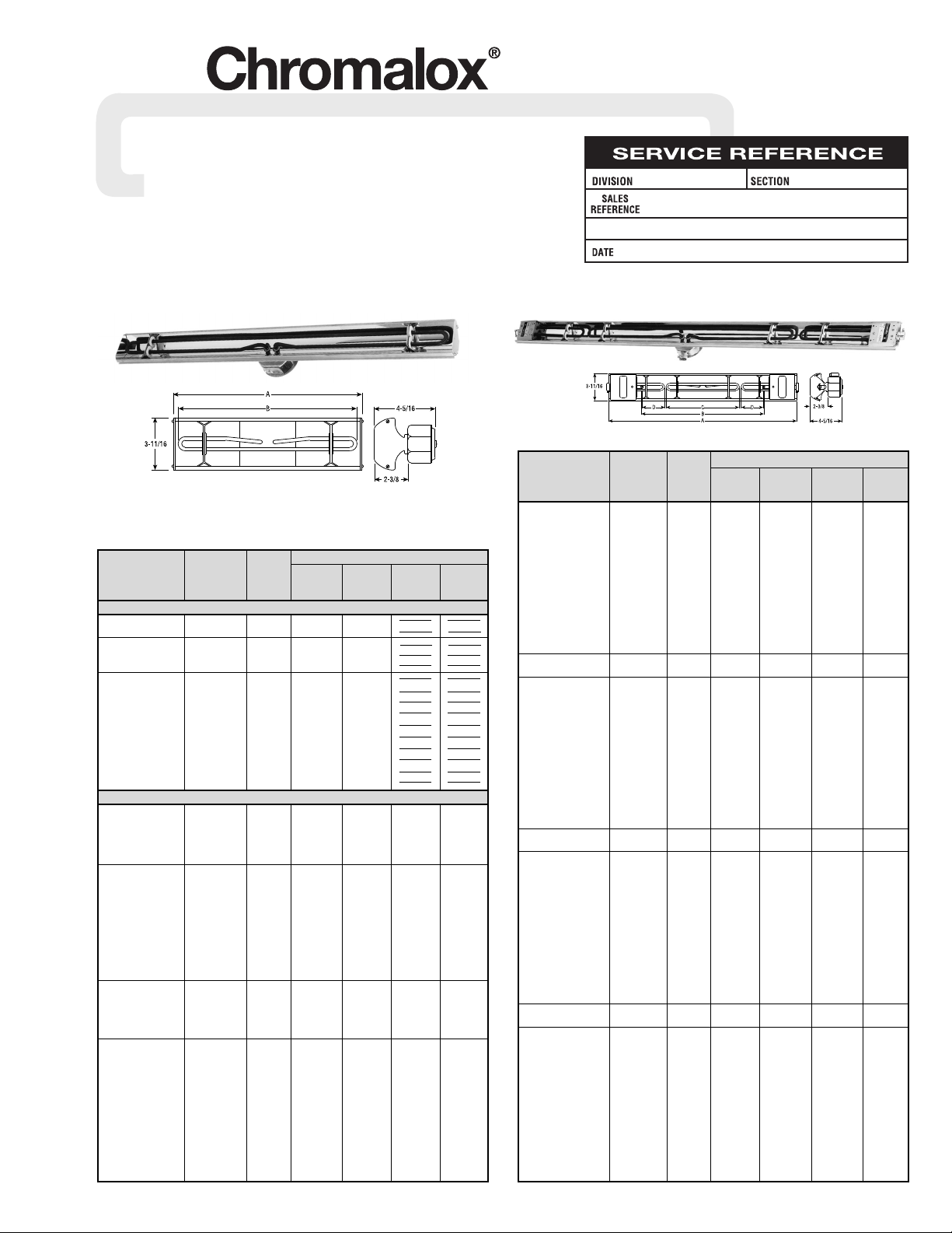
Specifications – Table A
Dimensions (In.)
BCD
A Total Center End
Model Volts kW Overall Heated Heated Heated
DU-RAD-458 6.04 75
7
/8 67 233/8 195/16
DU-RAD-466 6.42 797/8 71 323/8 195/16
DU-RAD-474 6.79 84 751/8 361/2 195/16
DU-RAD-482 7.17 881/16 791/8 409/16 195/16
DU-RAD-490 7.55 923/16 835/16 4411/16 195/16
DU-RAD-4102 208, 240, 8.12 983/16 895/16 5011/16 195/16
DU-RAD-4112 275 or 480 8.59 1035/16 947/16 5513/16 195/16
DU-RAD-4124 9.16 1091/2 1005/8 62 195/16
DU-RAD-4136 9.73 1151/2 1065/8 68 195/16
DU-RAD-4148 10.30 1215/8 1123/4 741/8 195/16
DU-RAD-4156 10.70 12511/16 11613/16 783/16 195/16
DU-RAD-4164 11.05 12913/16 12015/16 825/16 195/16
DU-RAD-4172 11.43 134 1251/8 861/2 195/16
DU-RAD-540 208, 240 6.60 815/8 723/4 191/4 263/4
DU-RAD-548 or 275 6.97 855/8 763/4 231/4 263/4
DU-RAD-558 7.44 903/4 817/8 283/8 263/4
DU-RAD-566 7.82 943/4 857/8 323/8 263/4
DU-RAD-574 8.19 987/8 90 361/2 263/4
DU-RAD-582 8.57 10215/16 941/16 409/16 263/4
DU-RAD-590 8.95 1071/16 983/16 4411/16 263/4
DU-RAD-5102 208, 240, 9.52 1131/16 1043/16 5011/16 263/4
DU-RAD-5112 275 or 480 9.99 1183/16 1095/16 5513/16 263/4
DU-RAD-5124 10.56 1243/8 1151/2 62 263/4
DU-RAD-5136 11.13 1303/8 1211/2 68 263/4
DU-RAD-5148 11.70 1361/2 1275/8 741/8 263/4
DU-RAD-5156 12.10 1409/16 13111/16 783/16 263/4
DU-RAD-5164 12.45 14411/16 13513/16 825/16 263/4
DU-RAD-5172 12.83 1487/8 140 861/2 263/4
DU-RAD-640 208, 240 7.60 933/4 847/8 191/4 3213/16
DU-RAD-648 or 275 7.97 973/4 887/8 231/4 3213/16
DU-RAD-658 8.44 1027/8 94 283/8 3213/16
DU-RAD-666 8.82 1067/8 98 323/8 3213/16
DU-RAD-674 9.19 111 1021/8 361/2 3213/16
DU-RAD-682 9.57 1151/16 1063/16 409/16 3213/16
DU-RAD-690 9.95 1193/16 1105/16 4411/16 3213/16
DU-RAD-6102 208, 240, 10.52 1253/16 1165/16 5011/16 3213/16
DU-RAD-6112 275 or 480 10.99 1305/16 1217/16 5513/16 3213/16
DU-RAD-6124 11.56 1361/2 1275/8 62 3213/16
DU-RAD-6136 12.13 1421/2 1335/8 68 3213/16
DU-RAD-6148 12.70 1485/8 1393/4 741/8 3213/16
DU-RAD-6156 13.10 15211/16 14313/16 783/16 3213/16
DU-RAD-6164 13.45 15613/16 14715/16 825/16 3213/16
DU-RAD-6172 13.83 161 1521/8 861/2 3213/16
DU-RAD-740 208, 240 8.80 106 971/8 191/4 3815/16
DU-RAD-748 or 275 9.17 110 1011/8 231/4 3815/16
DU-RAD-758 9.64 1151/8 1061/4 283/8 3815/16
DU-RAD-766 10.02 1191/8 1101/4 323/8 3815/16
DU-RAD-774 10.39 1231/4 1143/8 361/2 3815/16
DU-RAD-782 10.77 1275/16 1187/16 409/16 3815/16
DU-RAD-790 11.15 1317/16 1229/16 4411/16 3815/16
DU-RAD-7102 208, 240, 11.72 1377/16 1289/16 5011/16 3815/16
DU-RAD-7112 275 or 480 12.19 1429/16 13311/16 5513/16 3815/16
DU-RAD-7124 12.76 1483/4 1397/8 62 3815/16
DU-RAD-7136 13.33 1543/4 1457/8 68 3815/16
DU-RAD-7148 13.90 1607/8 152 741/8 3815/16
DU-RAD-7156 14.30 16415/16 1561/16 783/16 3815/16
DU-RAD-7164 14.65 1691/16 1603/16 825/16 3815/16
DU-RAD-7172 15.03 1731/4 1643/8 861/2 3815/16
Dimensions (In.)
BCD
A Total Center End
Model Volts kW Overall Heated Heated Heated
One Double-Hairpin Element Models
DU-RAD-040 120, 208 1.60 20
3
/8 1815/16
DU-RAD-048 240 or 275 1.97 2325/32 2225/32
DU-RAD-058 120, 208 2.44 287/8 2725/32
DU-RAD-066 240, 275 2.82 331/4 3125/32
DU-RAD-074 or 480 3.19 371/4 3525/32
DU-RAD-082 3.57 411/8 397/8
DU-RAD-090
208,
3.95 453/16 437/8
DU-RAD-0102 4.52 517/8 497/8
DU-RAD-0112
240,
4.99 563/16 547/8
DU-RAD-0124 5.56 621/2 6015/16
DU-RAD-0136
275
6.13 689/16 6615/16
DU-RAD-0148 6.70 751/2 7215/16
DU-RAD-0156
or
7.10 7813/16 77
DU-RAD-0164 7.45 82
11
/16 81
DU-RAD-0172
480
7.83 87 85
1
/16
Three Hairpin Element Models
DU-RAD-240 3.20 44
3
/4 357/8 191/4 85/16
DU-RAD-248
120, 208
3.57 483/4 397/8 231/4 85/16
DU-RAD-258
240 or 275
4.04 537/8 45 283/8 85/16
DU-RAD-266 4.42 577/8 49 323/8 85/16
DU-RAD-274 4.79 62 531/8 361/2 85/16
DU-RAD-282 5.17 661/16 573/16 409/16 85/16
DU-RAD-290 5.55 703/16 615/16 4411/16 85/16
DU-RAD-2102 6.12 769/16 675/16 5011/16 85/16
DU-RAD-2112 6.59 815/16 727/16 5513/16 85/16
DU-RAD-2124 208, 240 7.16 871/2 785/8 62 85/16
DU-RAD-2136 or 275 7.73 931/2 845/8 68 85/16
DU-RAD-2148 8.30 995/8 903/4 741/8 85/16
DU-RAD-2156 8.70 10311/16 9413/16 783/16 85/16
DU-RAD-2164 9.05 10713/16 9815/16 825/16 85/16
DU-RAD-2172 9.43 112 1031/8 861/2 85/16
DU-RAD-340 3.80 51 421/8 191/4 117/16
DU-RAD-348
120, 208
4.17 55 461/8 231/4 117/16
DU-RAD-358
240 or 275
4.64 601/8 511/4 283/8 117/16
DU-RAD-366 5.02 641/8 551/4 323/8 117/16
DU-RAD-374 5.39 681/4 593/8 361/2 117/16
DU-RAD-382 5.77 725/16 637/16 409/16 117/16
DU-RAD-390 6.15 767/16 679/16 4411/16 117/16
DU-RAD-3102 6.72 827/16 739/16 5011/16 117/16
DU-RAD-3112 7.19 879/16 7811/16 5513/16 117/16
DU-RAD-3124 7.76 933/4 847/8 62 117/16
DU-RAD-3136 208, 240 8.33 993/4 907/8 68 117/16
DU-RAD-3148 or 275 8.90 1057/8 97 741/8 117/16
DU-RAD-3156 9.30 10915/16 1013/16 783/16 117/16
DU-RAD-3164 9.65 1141/16 1053/16 825/16 117/16
DU-RAD-3172 10.03 1181/4 1093/8 861/2 117/16
DU-RAD-440 5.20 663/4 577/8 191/4 195/16
DU-RAD-448 5.57 703/4 617/8 231/4 195/16
Single Element
Three Elements
Page 2
2
INSTALLATION
MOUNTING
The system designer is responsible for the safety
of this equipment and should install adequate
back-up controls and safety devices with their
electric heating equipment. Where the consequences of failure could result in personal injury or
property damage, back-up controls are essential.
Before Installing
1. Open carton and remove heater at the place of installation.
Mounting clamps are in parts bag in carton.
2. Check nameplate volt and watt rating against your power supply
voltage and heating requirements of your installation. This nameplate of the complete assembly is located on the back of the heater
housing. Note: Single element heaters have one nameplate. Three
element heaters have four nameplates (one for each element and
one for the complete assembly).
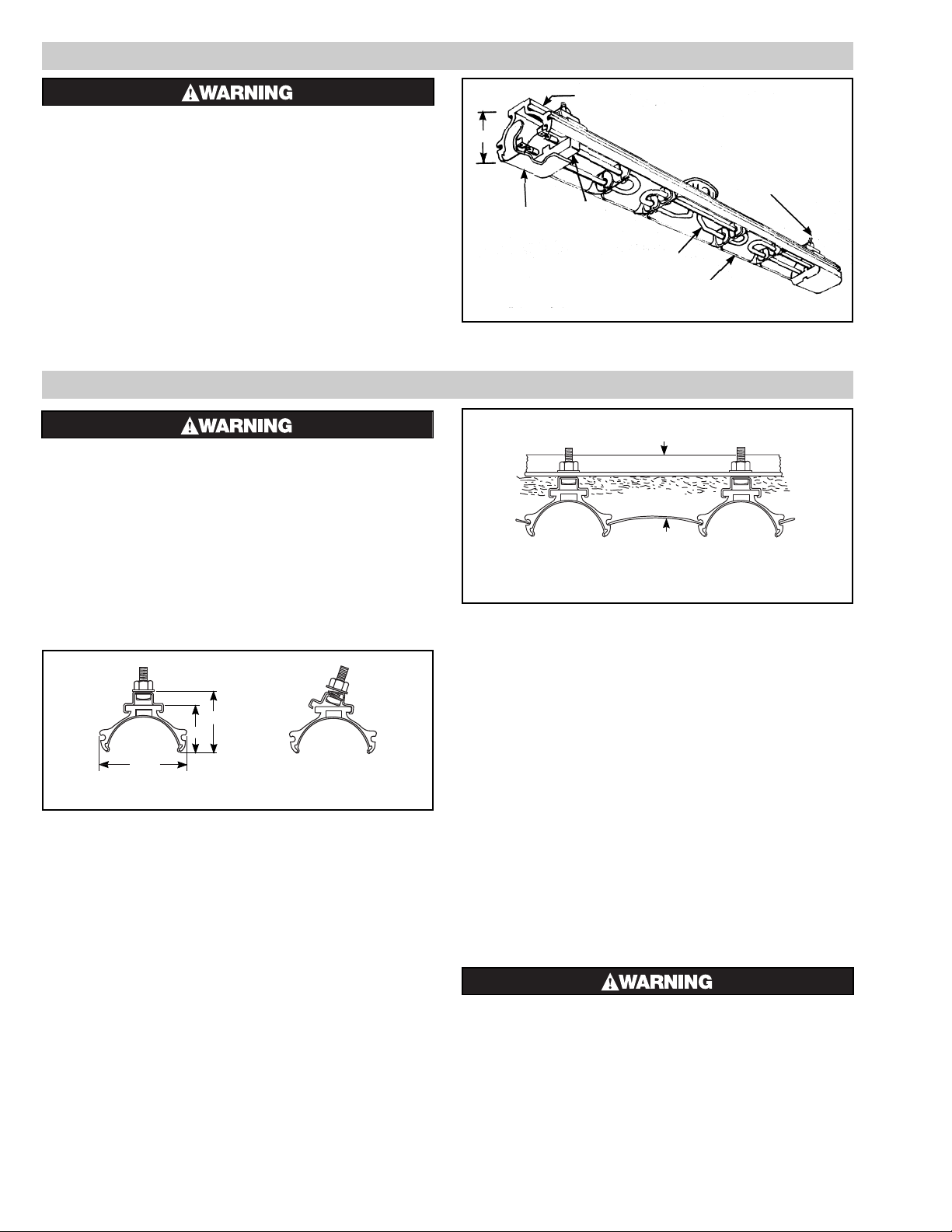
Housing
1 / "
7
8
Mounting Clamp
Assembly
Terminal
Cover
Terminal
Blocks
Polished Aluminum
Reflector
Element
Figure 1 — Heater Parts
and Dimensions
FIRE HAZARD. Since heaters are capable of developing high temperatures, extreme care should be
taken to maintain adequate spacing between heater
and combustible materials. Failure to comply can
result in personal injury or property damage.
Mounting
1. Clamps — Heaters are mounted by means of the mounting clamp
and 3/8” bolt assembly which is used as shown in Fig. 2. Clamp
assembly may be attached to heater by sliding over end or by snapping over top of extruded frame section at any point along its
length. (see Fig. 3) For proper heater support, the maximum distance between clamps must not exceed 48”. On extra-long heaters,
more than two clamps are furnished.
2. Mounting Holes — When heaters are mounted adjacent to each
other in the same plane, the minimum distance will depend on
whether the wiring to the center element enters the terminal box
through the connector furnished or through a right angle connector
(not furnished).
3. Framing — Where an extensive installation is being made, the use
of continuous slot metal framing manufactured by several concerns will be of assistance in saving time and money. The framing
is reusable.
4. Reflector Spacer Sheets — Where heaters are not mounted side
by side (see Fig. 4), reflector spacer sheets can be used between
heaters. These reflector spacer sheets and companion reflectors
consisting of an extruded aluminum housing with reflector sheet
and mounting clamps are available. Check factory or local
Chromalox Sales and Application Engineers.
5. Insulation — Where unusually high work temperatures are
encountered, it may be desirable to insulate with high temperature
insulation. Note: An air space should be left between backs of
heaters and insulation. (see Figure 4)
6. Ventilation — Where solvents, water, etc. are being evaporated
from work in process, it is necessary to provide substantial quantities of ventilation air to carry away the resulting vapors.
IMPORTANT –
In the case of solvents of an explosive nature, ventilation air must
be in sufficient volume to dilute the solvent vapor so that explosive
mixtures cannot occur. In order to comply with the standards of
safety required by the insurance companies, ventilation protection
and other facilities must be in accordance with NFPA Bulletin No.
86, entitled “Standard for Ovens and Furnaces”. This Bulletin
may be obtained from the Association at 470 Atlantic Avenue,
Boston Mass., 02110
FIRE/EXPLOSION HAZARD. This heater is not
intended for use in hazardous atmospheres where
flammable vapors, gases, liquids or other combustible atmospheres are present as defined in the
National Electrical Code. Failure to comply can
result in personal injury or property damage.
2 / "
15
16
2 / "
3
8
3 / "
11
16
Figure 2 Figure 3
Mounting Frame
Reflector
Spacer Sheet
Insulation
Figure 4
Page 3
ELECTRIC SHOCK HAZARD. Disconnect all power
before installing or servicing heater. Failure to do
so could result in personal injury or property damage. Heater must be installed by a qualified person
in accordance with the National Electrical Code,
NFPA 70.
ELECTRIC SHOCK HAZARD. Any installation involving electric heaters must be performed by a qualified person and must be effectively grounded in
accordance with the National Electrical Code to
eliminate shock hazard.
1. The power supply voltage should be the voltage as specified on the
heater nameplate located on the heater housing.
2. Wiring should be run in flexible or rigid metal conduit and must be
installed in accordance with the requirements of the National
Electrical Code and such other local requirements as may be
applicable. Note: High temperatures will oxidize copper. Do not
use copper wire in connecting this heater. Nickel-plated copper
wire, insulated in accordance with requirements for temperature
and voltage is recommended.
3. A sufficient length of this wire (not less than 12”) should be used
to extend from each heater terminal into a connection box location
where the temperature does not exceed 300˚F.
4. ELECTRICAL CONNECTIONS —
A. End Elements
Electrical connection to the heater end elements is made
through the 7/8” dia. opening in the end of the terminal cover
of the element assembly. A 1/2” flexible conduit connector is
provided with each element assembly for this purpose.
B. Center Elements
Electrical connection to the heater center element is made
through the 7/8” dia. opening in the 4” octagon conduit box for
the element assembly. A 1/2” flexible conduit connector is provided with each element assembly for this purpose.
5. ACCESS TO TERMINALS
A. End Elements
Access to the end element terminals is obtained by removing
the mounting bolt, nut and spacer (see Figure 9, items 9, 16 and
18) and sliding the terminal end of the element assembly out of
the housing.
B. Center Elements
Access to the center mounted element terminals is obtained by
removing the terminal box cover.
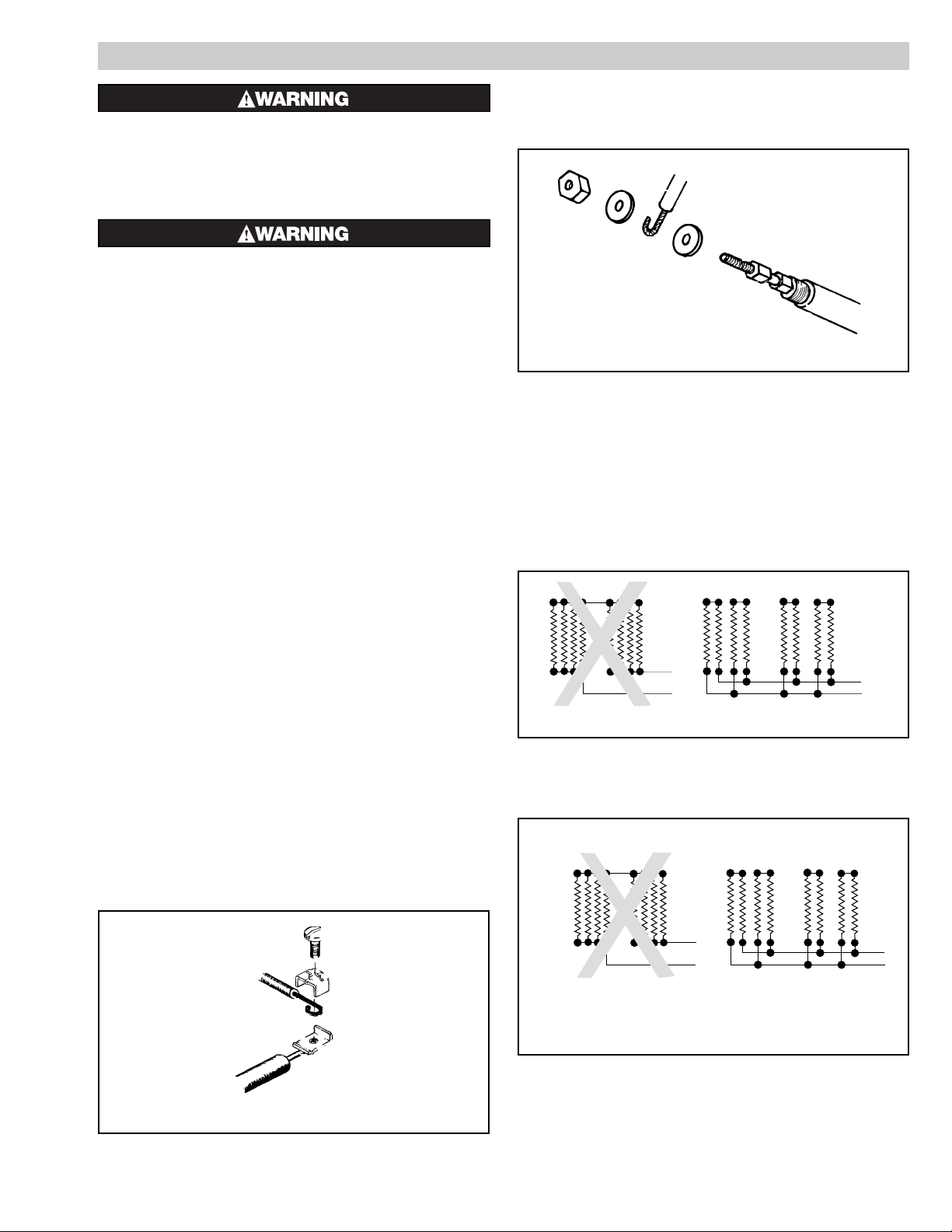
6. END ELEMENT TERMINAL ASSEMBLY
Assemble end terminal, screw and wire as shown in Figure 5. Hold
terminal with pliers and tighten the terminal screw securely with a
screwdriver.
7. CENTER ELEMENT TERMINAL ASSEMBLY
Assemble center terminal, washers, nut and wire as shown in
Figure 6. Hold terminal with pliers and tighten the terminal nut
securely with a wrench.
CAUTION: Terminal clip is spot-welded to element terminal pin
and over-tightening terminal screw may break the weld or shear
off terminal pin. However, either the screw or nut should be sufficiently tightened to eliminate arcing.
8. SERIES CONNECTION of Radiant Heaters of equal volt and
watt rating is permitted in all line voltages up to 600 volts. In making such series connections it is necessary to observe the “right”
(series-parallel) connection rather than the “wrong” (parallelseries) connection both shown in Figure 7. If heaters are connected according to the “wrong” illustration, failure of any heater will
cause progressive failure of other heaters still operating.
9. DELTA CONNECTIONS — When heaters occur in multiples of
three, they may be connected to, and balanced across, three-phase
lines. The most commonly used connection is the delta connection
illustrated in Figure 8.
Three phase Delta connections to minimize inductive effect in
conduits are made per this diagram. The rule: run all 3 three-phase
conductors in the same conduit as far as possible. For single-phase,
run only two conductors and follow the same rule.
3
WIRING
Wrong
Right
L1
L2
L2
L1
Radiant
Heaters
Wrong
Right
L1
L2
L2
L1
Radiant
Heaters
Figure 5 — End Element Terminal Assembly
Figure 7
Figure 8
Figure 6 — Center Element Terminal Assembly
Page 4

OPERATION
CAUTION: For your own safety —
Before energizing this heater:
1. Be sure all electrical connections are tightly made.
2. Be sure that all conductors are properly insulated.
3. Be sure that terminal box cover has been properly replaced, and
that secondary insulation bushings have not been omitted.
Controlling Radiant Intensity —
Standard Radiant Heaters are built to operate at 40 watts per
sq. inch on the element sheath. When it is desired to reduce radiant intensity, one or more of the following methods may be used.
1. INPUT CONTROLLERS. These motor-driven cycling devices
can be used to vary heater output capacity from 4 to 100%. They
are usually connected in holding coil circuit of magnetic contactors. See Chromalox Radiant Heater Manual for further information regarding Input Controllers and Contactors.
2. SOLID STATE THYRISTOR POWER CONTROLLERS.
For best non-contact control of radiant heat, a Series #6 Chromalox
Thyristor Power Controller with manual potentiometer setting is
recommended. Truly proportional output of from 0 – 100% can be
easily dialed-in to suit the particular product or process requirements. The Series #6 panels are pre-engineered, pre-packaged
assemblies in an enclosure with circuit disconnect provided and
ready for installation.
Maximum Ambient Temperatures —
Chromalox Radiant Heaters are not recommended for applications in ambient temperatures exceeding 450°F. Higher ambient
temperatures mean shorter heater life.
Maximum work temperature in a given time depends on several factors: Reflectivity of work, specific heat of work, mass of
work, kW input and losses from oven, and time of exposure. As
work temperature increases, the work loses heat by radiation and
by convection to the surrounding ambient. Although it is a general principle of a Radiant Heater application that work temperature
conventionally exceeds ambient temperature, in cases where
extremely high work temperatures are desired, it is necessary to
enclose the heaters in order to increase the ambient. If evaporation
of a liquid is desired as a result of increasing work temperature, it
is necessary to provide ventilation air in order to carry away the
evaporated liquid. Under carefully engineered circumstances, a
maximum work temperature of 600°F may be attained.
Low Megohm Condition — The refractory material used in
electric heaters may absorb moisture during transit, storage or
when subject to humid environments that will reduce the cold
insulation resistance (low megohm). Low megohm may result in a
high leakage current to ground and nuisance trips of ground fault
protection equipment. Normally, the megohm value increases after
heat-up. Typical insulation values are 5 megohm or greater on
complete assemblies or 20 megohm on individual unsealed elements. It is recommended that heaters with 1 megohm or less be
dried out before applying full power. If dried properly, low
megohm will not effect heater life or efficiency.
To correct a low megohm condition, remove terminal enclosure cover, gaskets, and terminal hardware. Bake heaters in an
oven at 300 to 350˚F for several hours or preferably overnight.
An alternate procedure is to cycle the heater in 10 to 15
minute periods at low voltage until megohm values are normal.
Sheath temperatures should not exceed 350˚F.
Note: Low megohm on heating elements with epoxy or hermetic seals cannot be serviced in the field. Typical resistance values when sealed are 200 megohm or greater. Contact Chromalox
service center at number listed.
FIRE OR SHOCK HAZARD. Moisture accumulation
in the element refractory material, element overtemperature or sheath corrosion can cause ground
fault to the element sheath, generating arcing and
molten metal. Install Ground Fault Protection to
prevent property damage.
ELECTRIC SHOCK HAZARD. Disconnect all power
before installing or servicing heater. Failure to do
so could result in personal injury or property damage. Heater must be installed by a qualified person
in accordance with the National Electrical Code,
NFPA 70.
To Remove Heating Element —
1. End Elements
A. Remove element assembly mounting nut and bolt 18 and 16
and element support clips (see Figure 9) and slide element
assembly out of housing.
B. Disconnect heating element from electrical leads at both ends.
C. Remove screws from porcelain terminal blocks.
D. Remove element support clips and secondary insulating bush-
ings.
E. Lift out element.
2. Center Elements
A. Remove terminal box cover.
B. Disconnect heating element from electrical leads and remove
all hardware from terminals.
C. Remove screws
24 from secondary insulator retaining brack-
et and remove bracket
22 .
D. Remove secondary insulation bushings
23 .
E. Unclip element support clips
12 from housing. (See Fig. 10)
F. Lift out element.
G. Remove element support clips
12 , bushing retaining clip 14
and insulating bushings 13 from element.
To Install Element —
Observe instructions for removing element and proceed in
reverse order. Be sure to replace secondary insulating bushings.
Care of Reflectors —
Reflectors should be cleaned periodically. A mild soap and
water solution or fine cleaning powder is best although more drastic means may be required if reflectors are badly soiled by chemical or other deposits. The reflector is aluminum. DO NOT use
alkali cleaners since alkalies will dull reflector. Mild non-alkaline
cleaners, such as used for scouring kitchen sinks, may be used.
Reflectors are replaceable and may be purchased from Chromalox.
MAINTENANCE
4
Page 5

RENEWAL PARTS IDENTIFICATION
PARTS COMMON TO ALL DU-RAD HEATERS
4 Reflector (center) . . . . . . . . . . . . . . . . . . . . . . . . . . . . . . . . . .234-114406-001
20 #10-32 Nut (4) . . . . . . . . . . . . . . . . . . . . . . . . . . . . . . . . . . . .200-075520-067
21 Cup Washer . . . . . . . . . . . . . . . . . . . . . . . . . . . . . . . . . . . . . . .328-075560-002
22 Bushing retaining bracket . . . . . . . . . . . . . . . . . . . . . . . . . . . .027-018140-001
23 Insulating bushing (2) . . . . . . . . . . . . . . . . . . . . . . . . . . . . . . .162-017459-001
24 #10-32 x
3
/8 lg. Screw (2) . . . . . . . . . . . . . . . . . . . . . . . . . . . .248-075414-093
25 #10 Flat Washer (2) . . . . . . . . . . . . . . . . . . . . . . . . . . . . . . . . .328-075528-036
PARTS COMMON TO ALL DU-RAD HEATERS
5 Terminal Block . . . . . . . . . . . . . . . . . . . . . . . . . . . . . . . . . . . .303-014316-001
6 Terminal Block . . . . . . . . . . . . . . . . . . . . . . . . . . . . . . . . . . . .303-014317-001
7 Terminal Cover . . . . . . . . . . . . . . . . . . . . . . . . . . . . . . . . . . .080-016868-001
8 Bracket . . . . . . . . . . . . . . . . . . . . . . . . . . . . . . . . . . . . . . . . .027-016372-001
9 Spacer . . . . . . . . . . . . . . . . . . . . . . . . . . . . . . . . . . . . . . . . . .032-075525-012
10
1
/2” Flexible Conduit Connector and Locknut . . . . . . . . . . . . .119-075454-005
& 200-075482-002
11 Terminal Screw . . . . . . . . . . . . . . . . . . . . . . . . . . . . . . . . . . .248-046044-002 (4)
12 Element Support Clip . . . . . . . . . . . . . . . . . . . . . . . . . . . . . .059-014304-002
13 Insulating Bushing . . . . . . . . . . . . . . . . . . . . . . . . . . . . . . . .032-013454-001
14 Bushing Retaining Clip . . . . . . . . . . . . . . . . . . . . . . . . . . . . .059-017175-001
15 Mounting Clamp Parts Bag - For mounting heaters with overall length less
than 74
1
/2”, use Parts Bag 162-013071-001. For heaters with 741/2” or larger
overall length, use two Parts Bags 168-013071-001.
MISCELLANEOUS HARDWARE
16 #8-32 Nut . . . . . . . . . . . . . . . . . . . . . . . . . . . . . . . . . . . . . . .200-075520-064
17 #8-32 x 1
3
/4” Screws . . . . . . . . . . . . . . . . . . . . . . . . . . . . . . .248-075512-194
18 #8-32 x 1” Screws . . . . . . . . . . . . . . . . . . . . . . . . . . . . . . . .248-075512-185
19 #8 Washer . . . . . . . . . . . . . . . . . . . . . . . . . . . . . . . . . . . . . . .328-075528-020
29 Saddle Clamp . . . . . . . . . . . . . . . . . . . . . . . . . . . . . . . . . . . .238-026539-001 (4)
Element
Support
Clip
Assembly
Terminal Box
Cover
Note: To order specify quantity, Model Number, Volts, kW.
Figure 9 — End Element
Figure 10 — Center Element
5
Page 6

12
Center End
Only Only 28
Total Element Element 3 Aluminum
Model kW Model* Model* Reflector Housing
Three Element Models
DU-RAD-240 3.20 UTU-40 UTU-2 234-016383-013 (2) 152-017463-001
DU-RAD-248 3.57 UTU-48 UTU-2 234-016383-014 (2) 152-017463-002
DU-RAD-258 4.04 UTU-58 UTU-2 234-016383-016 (2) 152-017463-004
DU-RAD-266 4.42 UTU-66 UTU-2 234-016383-018 (2) 152-017463-006
DU-RAD-274 4.79 UTU-74 UTU-2 234-016383-020 (2) 152-017463-008
DU-RAD-282 5.17 UTU-82 UTU-2 234-016383-022 (2) 152-017463-010
DU-RAD-290 5.55 UTU-90 UTU-2 234-016383-025 (2) 152-017463-013
DU-RAD-2102 6.12 UTU-102 UTU-2 234-016383-029 (2) 152-017463-017
DU-RAD-2112 6.59 UTU-112 UTU-2 234-016383-032 (2) 152-017463-019
DU-RAD-2124 7.16 UTU-124 UTU-2 234-016383-036 (2) 152-017463-023
DU-RAD-2136 7.73 UTU-136 UTU-2 234-016383-042 (2) 152-017463-027
DU-RAD-2148 8.30 UTU-148 UTU-2 234-016383-047 (2) 152-017463-032
DU-RAD-2156 8.70 UTU-156 UTU-2 234-016383-041 (2) 152-017463-035
DU-RAD-2164 9.05 UTU-164 UTU-2 234-016383-056 (2) 152-017463-038
DU-RAD-2172 9.43 UTU-172 UTU-2 234-016383-061 (2) 152-017463-042
12
Center End
Only Only 28
Total Element Element 3 Aluminum
Model kW Model* Model* Reflector Housing
Three Element Models
DU-RAD-340 3.80 UTU-40 UTU-3 234-016383-015 (2) 152-017463-003
DU-RAD-348 4.17 UTU-48 UTU-3 234-016383-017 (2) 152-017463-005
DU-RAD-358 4.64 UTU-58 UTU-3 234-016383-019 (2) 152-017463-007
DU-RAD-366 5.02 UTU-66 UTU-3 234-016383-021 (2) 152-017463-009
DU-RAD-374 5.39 UTU-74 UTU-3 234-016383-024 (2) 152-017463-012
DU-RAD-382 5.77 UTU-82 UTU-3 234-016383-027 (2) 152-017463-015
DU-RAD-390 6.15 UTU-90 UTU-3 234-016383-030 (2) 152-017463-017
DU-RAD-3102 6.72 UTU-102 UTU-3 234-016383-005 (2) 152-017463-020
DU-RAD-3112 7.19 UTU-112 UTU-3 234-016383-036 (2) 152-017463-023
DU-RAD-3124 7.76 UTU-124 UTU-3 234-016383-042 (2) 152-017463-027
DU-RAD-3136 8.33 UTU-136 UTU-3 234-016383-048 (2) 152-017463-032
DU-RAD-3148 8.90 UTU-148 UTU-3 234-016383-052 (2) 152-017463-036
DU-RAD-3156 9.30 UTU-156 UTU-3 234-016383-058 (2) 152-017463-040
DU-RAD-3164 9.65 UTU-164 UTU-3 234-016383-063 (2) 152-017463-044
DU-RAD-3172 10.03 UTU-172 UTU-3 234-016383-067 (2) 152-017463-047
*This is basic Model Number. See Table B or Table C for variation in element catalog number
depending upon voltage.
WIRING
Welded Retaining Rings
Type UTU – Single Hairpin Elements
Volts kW Model
120 or 240 0.8 UTU-2
208 or 275 0.8 UTU-2V
120 or 240 1.1 UTU-3
208 or 275 1.1 UTU-3V
208 or 275 1.8 UTU-4V
240 or 480 1.8 UTU-4
208 or 275 2.5 UTU-5V
240 or 480 2.5 UTU-5
208 or 275 3.0 UTU-6V
240 or 480 3.0 UTU-6
208 or 275 3.6 UTU-7V
240 or 480 3.6 UTU-7
Type UTU – Double Hairpin Elements
Volts kW Model
120 or 240 1.6 UTU-40
208 or 275 1.6 UTU-40V
120 or 240 1.97 UTU-48
208 or 275 1.97 UTU-48V
120, 240 or 480 2.44 UTU-58
208 or 275 2.44 UTU-58V
120, 240 or 480 2.82 UTU-66
208 or 275 2.82 UTU-66V
120, 240 or 480 3.19 UTU-74
208 or 275 3.19 UTU-74V
208 or 275 3.57 UTU-82V
240 or 480 3.57 UTU-82
208 or 275 3.95 UTU-90V
240 or 480 3.95 UTU-90
208 or 275 4.52 UTU-102V
240 or 480 4.52 UTU-102
208 or 275 4.99 UTU-112V
240 or 480 4.99 UTU-112
208 or 275 5.56 UTU-124V
240 or 480 5.56 UTU-124
208 or 275 6.13 UTU-136V
240 or 480 6.13 UTU-136
208 or 275 6.7 UTU-148V
240 or 480 6.7 UTU-148
208 or 275 7.1 UTU-156V
240 or 480 7.1 UTU-156
208 or 275 7.45 UTU-164V
240 or 480 7.45 UTU-164
208 or 275 7.83 UTU-172V
240 or 480 7.83 UTU-172
1
Basic 28
Element 3 Aluminum
Model kW Model* Reflector Housing
Single Element Models
DU-RAD-040 1.60 UTU-40 234-013411-067 (2) 152-114962-001
DU-RAD-048 1.97 UTU-48 234-013411-068 (2) 152-114962-002
DU-RAD-058 2.44 UTU-58 234-013411-069 (2) 152-114962-003
DU-RAD-066 2.82 UTU-66 234-013411-070 (2) 152-114962-004
DU-RAD-074 3.19 UTU-74 234-013411-071 (2) 152-114962-005
DU-RAD-082 3.57 UTU-82 234-013411-072 (2) 152-114962-006
DU-RAD-090 3.95 UTU-90 234-013411-073 (2) 152-114962-007
DU-RAD-0102 4.52 UTU-102 234-013411-074 (2) 152-114962-008
DU-RAD-0112 4.99 UTU-112 234-013411-075 (2) 152-114962-009
DU-RAD-0124 5.56 UTU-124 234-013411-076 (2) 152-114962-010
DU-RAD-0136 6.13 UTU-136 234-013411-077 (2) 152-114962-011
DU-RAD-0148 6.70 UTU-148 234-013411-078 (2) 152-114962-012
DU-RAD-0156 7.10 UTU-156 234-013411-079 (2) 152-114962-013
DU-RAD-0164 7.45 UTU-164 234-013411-080 (2) 152-114962-014
DU-RAD-0172 7.83 UTU-172 234-013411-081 (2) 152-114962-015
Figure 11 — Type UTU Single Hairpin Figure 12 — Type UTU Double Hairpin
Table B – Table C –
*This is basic Model Number. See Table B or Table C for variation in element model number
depending upon voltage.
6
Page 7

TESTING AND OPERATION
12
Center End
Only Only 28
Total Element Element 3 Aluminum
Model kW Model* Model* Reflector Housing
Three Element Models
DU-RAD-440 5.20 UTU-40 UTU-4 234-016383-023 (2) 152-017463-011
DU-RAD-448 5.57 UTU-48 UTU-4 234-016383-026 (2) 152-017463-014
DU-RAD-458 6.04 UTU-58 UTU-4 234-016383-028 (2) 152-017463-016
DU-RAD-466 6.42 UTU-66 UTU-4 234-016383-031 (2) 152-017463-018
DU-RAD-474 6.79 UTU-74 UTU-4 234-016383-034 (2) 152-017463-021
DU-RAD-482 7.17 UTU-82 UTU-4 234-016383-038 (2) 152-017463-024
DU-RAD-490 7.55 UTU-90 UTU-4 234-016383-040 (2) 152-017463-026
DU-RAD-4102 8.12 UTU-102 UTU-4 234-016383-045 (2) 152-017463-030
DU-RAD-4112 8.59 UTU-112 UTU-4 234-016383-051 (2) 152-017463-034
DU-RAD-4124 9.16 UTU-124 UTU-4 234-016383-057 (2) 152-017463-039
DU-RAD-4136 9.73 UTU-136 UTU-4 234-016383-066 (2) 152-017463-046
DU-RAD-4148 10.30 UTU-148 UTU-4 234-016383-071 (2) 152-017463-049
DU-RAD-4156 10.70 UTU-156 UTU-4 234-016383-075 (2) 152-017463-052
DU-RAD-4164 11.05 UTU-164 UTU-4 234-016383-077 (2) 152-017463-054
DU-RAD-4172 11.43 UTU-172 UTU-4 234-016383-080 (2) 152-017463-057
DU-RAD-540 6.60 UTU-40 UTU-5 234-016383-033 (2) 152-017463-019
DU-RAD-548 6.97 UTU-48 UTU-5 234-016383-035 (2) 152-017463-022
DU-RAD-558 7.44 UTU-58 UTU-5 234-016383-039 (2) 152-017463-025
DU-RAD-566 7.82 UTU-66 UTU-5 234-016383-043 (2) 152-017463-028
DU-RAD-574 8.19 UTU-74 UTU-5 234-016383-046 (2) 152-017463-031
DU-RAD-582 8.57 UTU-82 UTU-5 234-016383-050 (2) 152-017463-033
DU-RAD-590 8.95 UTU-90 UTU-5 234-016383-055 (2) 152-017463-037
DU-RAD-5102 9.52 UTU-102 UTU-5 234-016383-062 (2) 152-017463-043
DU-RAD-5112 9.99 UTU-112 UTU-5 234-016383-067 (2) 152-017463-047
DU-RAD-5124 10.56 UTU-124 UTU-5 234-016383-073 (2) 152-017463-050
DU-RAD-5136 11.13 UTU-136 UTU-5 234-016383-078 (2) 152-017463-055
DU-RAD-5148 11.70 UTU-148 UTU-5 234-016383-082 (2) 152-017463-058
DU-RAD-5156 12.10 UTU-156 UTU-5 234-016383-084 (2) 152-017463-060
DU-RAD-5164 12.45 UTU-164 UTU-5 234-016383-087 (2) 152-017463-062
DU-RAD-5172 12.83 UTU-172 UTU-5 234-016383-089 (2) 152-017463-063
*This is basic Model Number. See Table B and C for variation in model number depending upon voltage.
Note: Part Numbers suffixed by a number in ( ) indicates the number of parts of same part number used or supplied if more than one.
12
Center End
Only Only 28
Total Element Element 3 Aluminum
Model kW Model* Model* Reflector Housing
Three Element Models
DU-RAD-640 7.60 UTU-40 UTU-6 234-016383-042 (2) 152-017463-027
DU-RAD-648 7.97 UTU-48 UTU-6 234-016383-044 (2) 152-017463-029
DU-RAD-658 8.44 UTU-58 UTU-6 234-016383-049 (2) 152-017463-033
DU-RAD-666 8.82 UTU-66 UTU-6 234-016383-054 (2) 152-017463-037
DU-RAD-674 9.19 UTU-74 UTU-6 234-016383-060 (2) 152-017463-041
DU-RAD-682 9.57 UTU-82 UTU-6 234-016383-064 (2) 152-017463-072
DU-RAD-690 9.95 UTU-90 UTU-6 234-016383-070 (2) 152-017463-073
DU-RAD-6102 10.52 UTU-102 UTU-6 234-016383-074 (2) 152-017463-051
DU-RAD-6112 10.99 UTU-112 UTU-6 234-016383-078 (2) 152-017463-055
DU-RAD-6124 11.56 UTU-124 UTU-6 234-016383-081 (2) 152-017463-058
DU-RAD-6136 12.13 UTU-136 UTU-6 234-016383-085 (2) 152-017463-061
DU-RAD-6148 12.70 UTU-148 UTU-6 234-016383-088 (2) 152-017463-063
DU-RAD-6156 13.10 UTU-156 UTU-6 234-016383-091 (2) 152-017463-064
DU-RAD-6164 13.45 UTU-164 UTU-6 234-016383-093 (2) 152-017463-066
DU-RAD-6172 13.83 UTU-172 UTU-6 234-016383-095 (2) 152-017463-067
DU-RAD-740 8.80 UTU-40 UTU-7 234-016383-053 (2) 152-017463-036
DU-RAD-748 9.17 UTU-48 UTU-7 234-016383-059 (2) 152-017463-040
DU-RAD-758 9.64 UTU-58 UTU-7 234-016383-065 (2) 152-017463-045
DU-RAD-766 10.02 UTU-66 UTU-7 234-016383-069 (2) 152-017463-048
DU-RAD-774 10.39 UTU-74 UTU-7 234-016383-072 (2) 152-017463-071
DU-RAD-782 10.77 UTU-82 UTU-7 234-016383-076 (2) 152-017463-053
DU-RAD-790 11.15 UTU-90 UTU-7 234-016383-079 (2) 152-017463-056
DU-RAD-7102 11.72 UTU-102 UTU-7 234-016383-083 (2) 152-017463-059
DU-RAD-7112 12.19 UTU-112 UTU-7 234-016383-085 (2) 152-017463-061
DU-RAD-7124 12.76 UTU-124 UTU-7 234-016383-089 (2) 152-017463-063
DU-RAD-7136 13.33 UTU-136 UTU-7 234-016383-092 (2) 152-017463-065
DU-RAD-7148 13.90 UTU-148 UTU-7 234-016383-094 (2) 152-017463-067
DU-RAD-7156 14.30 UTU-156 UTU-7 234-016383-096 (2) 152-017463-068
DU-RAD-7164 14.65 UTU-164 UTU-7 234-016383-097 (2) 152-017463-069
DU-RAD-7172 15.03 UTU-172 UTU-7 234-016383-098 (2) 152-017463-070
7
Page 8

2150 N. RULON WHITE BLVD., OGDEN, UT 84404
Phone: 1-800-368-2493 www.chromalox.com
Limited Warranty:
Please refer to the Chromalox limited warranty applicable to this product at
http://www.chromalox.com/customer-service/policies/termsofsale.aspx.
 Loading...