

Page 1
(Supersedes PG436-1)
PG436-2
VTS
161-304901-004
JUNE, 2010
4
DATE
SALES
REFERENCE
DIVISION SECTION
Chromalox
®
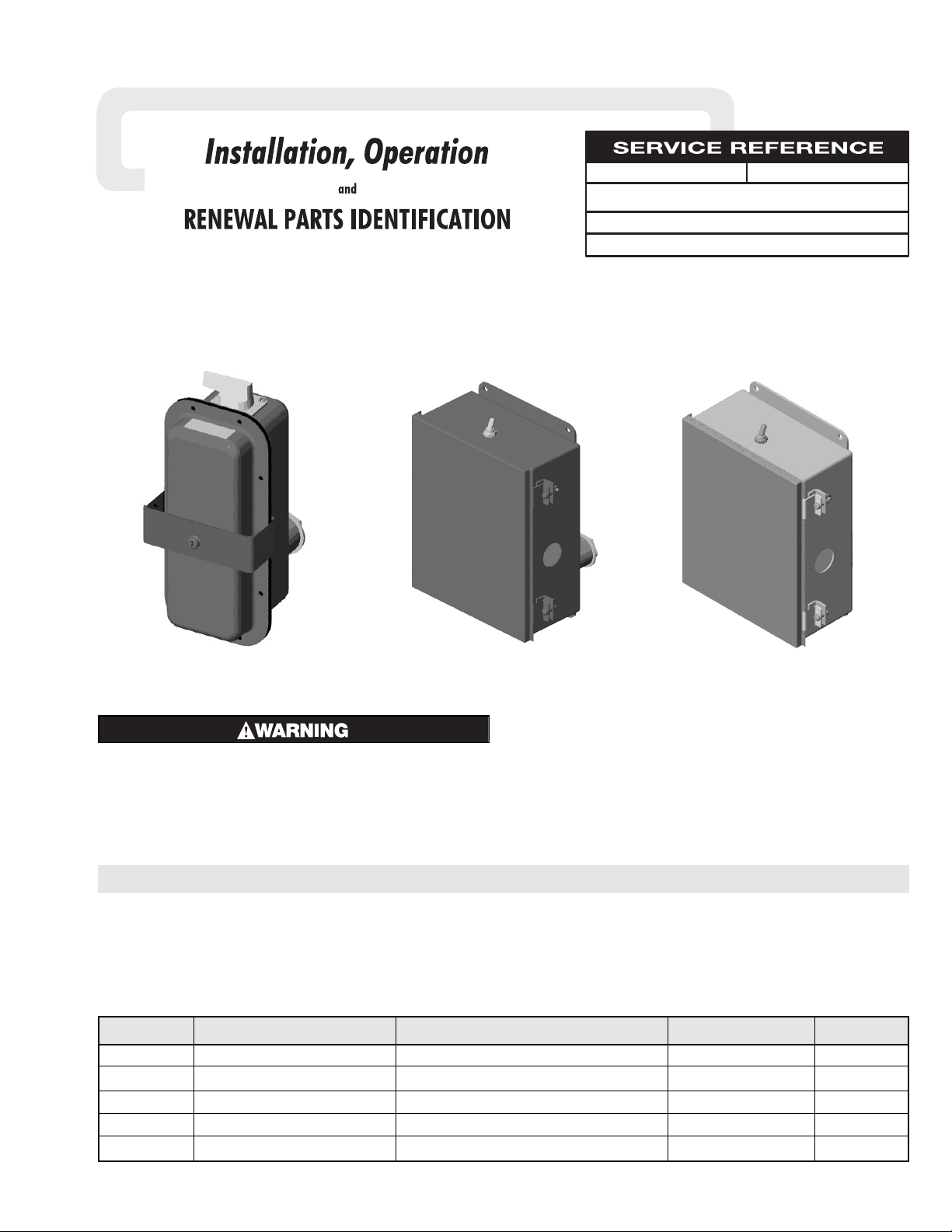
DS-50600, STAR-GF, STAR-TIP and STAR-TG Kits
For Adding Optional Kits to STAR Radiant Heaters
© 2008 Chromalox, Inc.
Table 1
Kit Model Used with Heater Model Kit Function Installation Instructions Wiring Diagram
DS-50600 Fixed STAR-06A and STAR-14A Adds Integral Disconnect Switch See Page 2 Fig. 1
DS-50600 Portable STAR-06A and STAR-14A Adds Integral Disconnect Switch See Page 3 Fig. 1
STAR-GF All Fixed STAR Adds Wall Mounted Ground Fault Sensor See Page 4 Fig. 2
STAR-TIP Portable STAR-06A and STAR-14A Adds Tip Over Shut Down See Page 5 Fig. 3
STAR-TG Portable STAR-06A and STAR-14A Adds Tip Over Shut Down with Ground Fault Sensor See Pages 5 and 6 Fig. 4
GENERAL
To use this instruction sheet from Table 1 select the Installation
Instructions by matching the Kit Model to the Heater Model. If a
match does not exist consult Factory.
The kits are add-on options to STAR Radiant Heaters. The
installation and renewal parts identification for the heater is covered in the instruction sheet provided with the heater. SAVE
BOTH COPIES OF THE INSTRUCTION SHEET.
ELECTRIC SHOCK HAZARD. Disconnect all power
to heater before installing or servicing kit(s).
Failure to do so could result in personal injury or
property damage. Kit(s) must be installed by a
qualified person in accordance with the National
Electrical Code, NFPA 70.
Always check to make certain the voltage rating of the kit
matches the voltage rating of the heater (See Nameplates).
Model DS50600
STAR-GFModel STAR-TIP
STAR-TG
Page 2
2
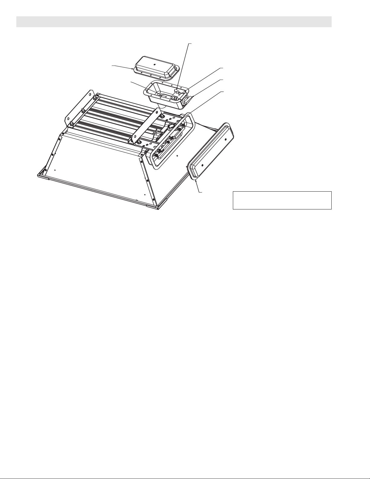
Cover
(Step 4)
3 Pole Terminal Block w/Ground
(Step 8)
Opening for 1" Conduit Fitting
(Step 8)
3 Pole Disconnect Switch
On-Off Handle
Chase Nipple and Gasket
(Step 5)
Cover
(Step 3)
INSTALLATION INSTRUCTIONS
INSTRUCTIONS FOR INSTALLING DISCONNECT SWITCH ON
6 AND 13.5 KW FIXED RADIANT HEATERS
1. Addition of the disconnect switch assy must be done by a qualified electrician.
2. The disconnect switch kit includes the following parts.
Verify that all parts are included, if not, contact the Chromalox Service Dept.
(1)Disconnect Switch Assy
(2)Mounting Bracket (Not Used)
(3)Hardware Kit: (Not Used)
Two 3/8” Lockwashers
Two 3/8” Nuts
One Self Tapping Screw
One Gasket for Cord Fitting (Supplied Separately)
3. Remove the screws in the heater terminal box. Remove cover.
4. Remove cover from disconnect switch assy using same method as Step3.
5. Remove Chase nipple and gasket from opening end of disconnect switch assy. Slide Chase nipple
through hole in heater terminal box and then gasket over threads.
6. Thread Chase nipple into threaded coupling. Wrench tighten nipple.
7. Uncoil three (3) leads marked “1”, “2”, and “3” located in disconnect switch housing. Thread these
three (3) leads through the nipple. Attach leads to the terminals indicated on the heater wiring label
located on the cover of the heater. If using for single phase, cap off lead marked “3”.
8. Attach conduit to the opening in the disconnect switch housing. Connect leads to terminal block.
9. Inspect all wiring to make sure all connections are tight, adequate electrical clearances exist, and
all electrical practices are met.
10.Install both covers.
Drawing shows 6 kW heater.
13.5 kW heater steps are identical.
Page 3
3
Self Tapping Screw
(Step 8)
On-Off Handle
Cover
(Step 5)
3 Pole Disconnect Switch
3 Pole Terminal Block w/Ground (Step 11)
Chase Nipple and Gasket
(Step 6)
Cover
(Step 3)
Mounting Bracket
(Step 4)
3/8" Lockwasher and Nut
(Step 4)
Opening for 1" Cord Fitting
(Step 11)
INSTALLATION INSTRUCTIONS
INSTRUCTIONS FOR INSTALLING DISCONNECT SWITCH ON
6 AND 13.5 KW PORTABLE RADIANT HEATERS
1. Addition of the disconnect switch assy must be done by a qualified electrician.
2. The disconnect switch kit includes the following parts.
Verify that all parts are included, if not, contact the Chromalox Service Dept.
(1)Disconnect Switch Assy
(2)Mounting Bracket
(3)Hardware Kit:
Two 3/8” Lockwashers
Two 3/8” Nuts
One Self Tapping Screw
One Gasket for Cord Fitting (Supplied Separately)
3. Remove the screws in the heater terminal box. Remove cover.
4. Place mounting bracket over 3/8” studs as shown. Place lockwashers on studs and secure in place
with 3/8” nuts.
5. Remove cover from disconnect switch assy using same method as Step 3.
6. Remove Chase nipple and gasket from opening end of disconnect switch assy. Slide Chase nipple
through hole in heater terminal box and then gasket over threads.
7. Thread Chase nipple into threaded coupling. Hand tighten only.
8. LIne up hole in bottom of disconnect switch housing with hole in mounting bracket. Tap 10-32 x
1/2” long screw into mounting bracket.
9. Wrench tighten Chase nipple installed in Step 6.
10.Uncoil three (3) leads marked “1”, “2”, and “3” located in disconnect switch housing. Thread these
three (3) leads through the nipple. Attach leads to the terminals indicated on the heater wiring label
located on the cover of the heater. If using for single phase, cap off lead marked “3”.
11.Attach cord assy to the opening in the disconnect switch housing. Connect leads of cord to terminal block.
12.Inspect all wiring to make sure all connections are tight, adequate electrical clearances exist, and
all electrical practices are met.
13.Install both covers.
Drawing shows 6 kW heater.
13.5 kW heater steps are identical.
Page 4

4
INSTRUCTIONS FOR INSTALLING WALL MOUNTED STAR-GF
1. Check voltage on heater nameplate and STAR-GF to make cer-
tain voltages are the same. If voltages do not match, consult
factory.
2. The STAR-GF will provide ground fault protection for STAR
Radiant heaters. The number of heaters serviced by one (1)
STAR-GF is dependent on the number and length of the heating elements. See Table 2.
3. See Instruction Sheet PG434 (provided with heater) for
IMPORTANT INSTRUCTIONS and WIRING.
4. Using the STAR-GF as a template mark mounting holes on
wall. Use an anchoring method adequate to support the weight.
5. Wire between STAR-GF and heater, wire to terminal block.
Service entrance wiring to be made to contactor connectors.
For wire gage see Table 1 of PG434.
6. The ground fault sensor has been factory set at .03 Amps, DO
NOT CHANGE THE SETTING.
Table 2
Heater Model Max. No. of Heaters
STAR-02A 6
STAR-05A 3
STAR-06A 2
STAR-14A 1
STAR-GF Mounting Dimensions
8-1/2"
6"
10-3/4"
10"
6"
3/4
3/4
5/16 Dia.
Tripped Indicator
Light is On
Is this the
initial
installation?
Is this the first
time heater is
used for the
season?
Is the set point of
the GF sensor set
at a value less than
.03 amps?
Did the problem
occur after
working properly
during part of this
heating season?
This condition indicates
at least one element is
about to fail.
Call Chromalox
Service Dept.
1 800-368-2493
Close cover.
Does the
heater
operate?
Does the heater
operate?
1. Replace all elements.
2. Flip toggle switch back
and forth, one time to
reset GF sensor.
Do you want to
reduce future
down time and
maintenance
costs?
1. Turn set point dial
clockwise to .03 amps.
2. Flip toggle switch mounted ontop
of enclosure back and forth one
time, (this resets the GF sensor).
Unbuss wiring, check insulation resistance
on each element.
1. Each element to have at least 10 Meg
terminal to sheath.
2. If element does not have at least 10 Meg.
dry out element by applying half of the
rated voltage for one hour.
3. Rebuss elements, re-energize heater, flip
toggle switch back and forth, one time
to reset GF sensor.
Does the heater
operate?
Call Chromalox
Service Dept.
1 800-368-2493
Does the
heater
operate?
Close cover.
Close cover.
Close cover.
Unbuss wiring, check insulation resistance
on each element.
1. Each element to have at least 10 Meg
terminal to sheath.
2. If element does not have at least 10 Meg.
dry out element by applying half of the
rated voltage for one hour.
3. Rebuss elements, re-energize heater, flip
toggle switch back and forth, one time
to reset GF sensor.
START
Yes
No
Yes
Yes
Yes
Yes
Yes
Yes
Yes
Yes
No
No
No
No
No
No
No
The Chromalox STAR-GF ground fault sensor provides a reli-
able and cost effective method for sensing ground faults. The purpose is to monitor for ground faults, sense potential heater failure
symptoms and to protect equipment.
The current-carrying wires are routed through the current
transformer on the control. When ground current reaches the level
set by the trip point adjustment, (.03 Amps), the relay trips, illuminates the tripped LED and provides an output signal which deenergizes the magnetic contactor.
ELECTRIC SHOCK HAZARD. Disconnect all power
to heater before installing or servicing kit(s).
Failure to do so could result in personal injury or
property damage. Kit(s) must be installed by a
qualified person in accordance with the National
Electrical Code, NFPA 70.
If heating element(s) fail to operate:
1. Open door of enclosure. DANGER: Hazard of Electric
Shock. If "Tripped" indicator is on, this indicates one or more
heating elements are about to fail. Disconnect power and follow the GF Troubleshooting Diagram below.
2. If the "Tripped" indicator is not on, check for blown fuses or
failed components within the heater's electrical system.
MAINTENANCE
GF TROUBLESHOOTING DIAGRAM
Page 5

5
VIEW SHOWN WITH TIP OVER SWITCH ASSY COVER REMOVED
MOUNTING BRACKET
(STEP 4)
3/8" LOCKWASHER AND NUT (STEP 4)
SELF TAPPING SCREW (STEP 8)
HEAT/NO HEAT
3 POLE CONTACTOR
OPENING FOR 1" CORD FITTING (STEP 11)
CHASE NIPPLE AND GASKET (STEP 6)
COVER (STEP 3)
INSTALLATION INSTRUCTIONS
INSTRUCTIONS FOR INSTALLING “STAR-TIP” AND “STAR-TG” ON
6 AND 13.5 KW PORTABLE RADIANT HEATERS
1. Addition of the tip over switch assy must be done by a qualified electrician.
2. The tip over switch assy includes the following parts.
Verify that all parts are included, if not, contact the Chromalox Service Dept.
(1)Tip Over Switch Assy
(2)Mounting Bracket
(3)Hardware Kit:
Two 3/8” Lockwashers
Two 3/8” Nuts
Two Self Tapping Screw
One Gasket for Cord Fitting (Supplied Separately)
3. Remove the screws in the heater terminal box. Remove cover.
4. Place mounting bracket over 3/8” studs as shown. Place lockwashers on studs and secure in place
with 3/8” nuts.
5. Remove cover from tip over switch assy using same method as Step 3.
6. Remove Chase nipple and gasket from open end of tip over switch assy. Slide Chase nipple through
hole in heater terminal box and then gasket over threads.
7. Thread Chase nipple into threaded coupling. Hand tighten nipple.
8. Line up hole in bottom of tip over switch with hole in mounting bracket. Tap 10-32 x 1/2” long
screws into mounting bracket.
9. Wrench tightened Chase nipple installed in Step 6.
10.Uncoil three (3) leads marked “1”, “2”, and “3” located in disconnect switch housing. Thread these
three (3) leads through the nipple. Wire nut leads of tip over switch to leads of heater. If using for
single phase, cap off lead marked “3”.
11.Attach cord assembly to the opening in the tip over switch housing. Connect leads of cord to the
contactor.
12.Inspect all wiring to make sure all connections are tight, adequate electrical clearances exist, and
all electrical practices are met.
13.Install both covers.
Drawing shows 6 kW heater.
13.5 kW heater steps are identical.
Page 6

6
MAINTENANCE
The Chromalox STAR-TG tip over cutout with ground fault
sensor provides a reliable and cost effective method for sensing
ground faults and to shut off the heater in case of tip-over. The purpose of the ground fault control is to monitor for ground faults,
sense potential heater failure symptoms and to protect equipment.
The current-carrying wires are routed through the current
transformer on the control. When ground current reaches the level
set by the trip point adjustment, (.03 amps), the relay trips, illuminates the tripped LED and provides an output signal which deenergizes the magnetic contactor.
ELECTRIC SHOCK HAZARD. Disconnect all power
to heater before installing or servicing kit(s).
Failure to do so could result in personal injury or
property damage. Kit(s) must be installed by a
qualified person in accordance with the National
Electrical Code, NFPA 70.
If heating element(s) fail to operate:
1. Open door of enclosure. DANGER: Hazard of Electric
Shock.
2. If "Tripped" indicator is not on, check for blown fuses or failed
electrical components in the heater’s electrical system including the tip over trip mechanism.then this indicates one or more
heating elements are about to fail.
3. Check pendulums on the tip over switch mechanisms to be sure
they are not blocked.
4. If the "Tripped" indicator is on, then this indicates one or more
heating elements are about to fail. Disconnect power and follow the GF Troubleshooting Diagram below.
Tripped Indicator
Light is On
Is this the
initial
installation?
Is this the first
time heater is
used for the
season?
Is the set point of
the GF sensor set
at a value less than
.03 amps?
Did the problem
occur after
working properly
during part of this
heating season?
This condition indicates
at least one element is
about to fail.
Call Chromalox
Service Dept.
1 800-368-2493
Close cover.
Does the
heater
operate?
Does the heater
operate?
1. Replace all elements.
2. Flip toggle switch back
and forth, one time to
reset GF sensor.
Do you want to
reduce future
down time and
maintenance
costs?
1. Turn set point dial
clockwise to .03 amps.
2. Flip toggle switch mounted ontop
of enclosure back and forth one
time, (this resets the GF sensor).
Unbuss wiring, check insulation resistance
on each element.
1. Each element to have at least 10 Meg
terminal to sheath.
2. If element does not have at least 10 Meg.
dry out element by applying half of the
rated voltage for one hour.
3. Rebuss elements, re-energize heater, flip
toggle switch back and forth, one time
to reset GF sensor.
Does the heater
operate?
Call Chromalox
Service Dept.
1 800-368-2493
Does the
heater
operate?
Close all covers.
Unbuss wiring, check insulation resistance
on each element.
1. Each element to have at least 10 Meg
terminal to sheath.
2. If element does not have at least 10 Meg.
dry out element by applying half of the
rated voltage for one hour.
3. Rebuss elements, re-energize heater, flip
toggle switch back and forth, one time
to reset GF sensor.
START
Yes
No
Yes
Yes
Yes
Yes
Yes
Yes
Yes
Yes
No
No
No
No
No
No
No
Close all covers.
Close all covers.
TG TROUBLESHOOTING DIAGRAM
Page 7

7
WIRING
For applicable wiring diagram see Table 1
GROUND FAULT
MONITOR
TOGGLE SWITCH
SEE NOTES
ATTACHED TO
AUXILLARY TERMINALS
NOTES:
1. USE 90 DEG. C. MIN. WIRING.
2. USE COPPER CONDUCTORS ONLY.
3. VERIFY THAT VOLTAGE OF "STAR-TG"
MATCHES VOLTAGE OF HEATER.
BLACK
TRANSFORMER
WHITE
TO TERMINALS
INSIDE HEATER
JUNCTION BOX
POWER LEADS MUST
PASS THROUGH CURRENT
TRANSFORMER POSITION
OF GROUND FAULT
MONITOR
PRI. SIDE TRANSFORMER CONNECTION:
208V = BLK AND RED
240V = BLK AND ORG
277V = BLK AND BRN
380V = BLK AND VIOLET
480V = BLK AND BLK/RED
600V = BLK AND GRAY
UNUSED LEADS CAPPED OFF.
SUPPLY
CONTACTOR
CO
NC
NO
L2
L3
L1
13 2
G
L3
L2
GROUND FAULT
MONITOR
TOGGLE
SWITCH
TIPOVER
SWITCH
TIPOVER
SWITCH
CONTACTOR
SEE NOTES
ATTACHED TO
AUXILLARY
TERMINALS
NOTES:
1. USE 90 DEG. C. MIN. WIRING.
2. USE COPPER CONDUCTORS ONLY.
3. VERIFY THAT VOLTAGE OF "STAR-TG"
MATCHES VOLTAGE OF HEATER.
BLACK
TRANSFORMER
WHITE
TO TERMINALS
INSIDE HEATER
JUNCTION BOX
POWER LEADS MUST
PASS THROUGH CURRENT
TRANSFORMER POSITION
OF GROUND FAULT
MONITOR
PRI. SIDE TRANSFORMER CONNECTION:
208V = BLK AND RED
240V = BLK AND ORG
277V = BLK AND BRN
480V = BLK AND BLK/RED
380V = BLK AND VIOLET
600V = BLK AND GRAY
UNUSED LEADS CAPPED OFF.
SUPPLY
CO
NC
NO
3
2 1
L1
TOGGLE
SWITCH
TIPOVER
SWITCH
TIPOVER
SWITCH
CONTACTOR
TRANSFORMER
BLACK
WHITE
TO TERMINALS
INSIDE HEATER
JUNCTION BOX
NOTES:
1. USE 90 DEG. C. MIN. WIRING.
2. USE COPPER CONDUCTORS ONLY.
3. VERIFY THAT VOLTAGE OF "STAR-TIP"
MATCHES VOLTAGE OF HEATER.
PRI. SIDE TRANSFORMER CONNECTION:
208V = BLK AND RED
240V = BLK AND ORG
277V = BLK AND BRN
380V = BLK AND VIOLET
480V = BLK AND BLK/RED
600V = BLK AND GRAY
UNUSED LEADS CAPPED OFF.
3
L3
L2
L1
2
1
1
2
4
3
6
5
DISCONNECT
SWITCH
TERMINAL BLOCK
NOTES:
1. USE 90 DEG. C. MIN. WIRING.
2. USE COPPER CONDUCTORS ONLY.
3. TO MAINTAIN THE ENVIRONMENTAL
RATING OF THIS ENCLOSURE, USE
ONLY UL LISTED OR RECOGNIZED
LIQUID TIGHT CONDUIT HUBS.
TO TERMINALS
INSIDE HEATER
JUNCTION BOX
3
2
1
GRN
L1 L2
L3
Fig. 1
Fig. 2
Fig. 3
Fig. 4
Page 8
TA - T0 - EF
Litho in U.S.A.
2150 N. RULON WHITE BLVD., OGDEN, UT 84404
Phone: 1-800-368-2493 www.chromalox.com
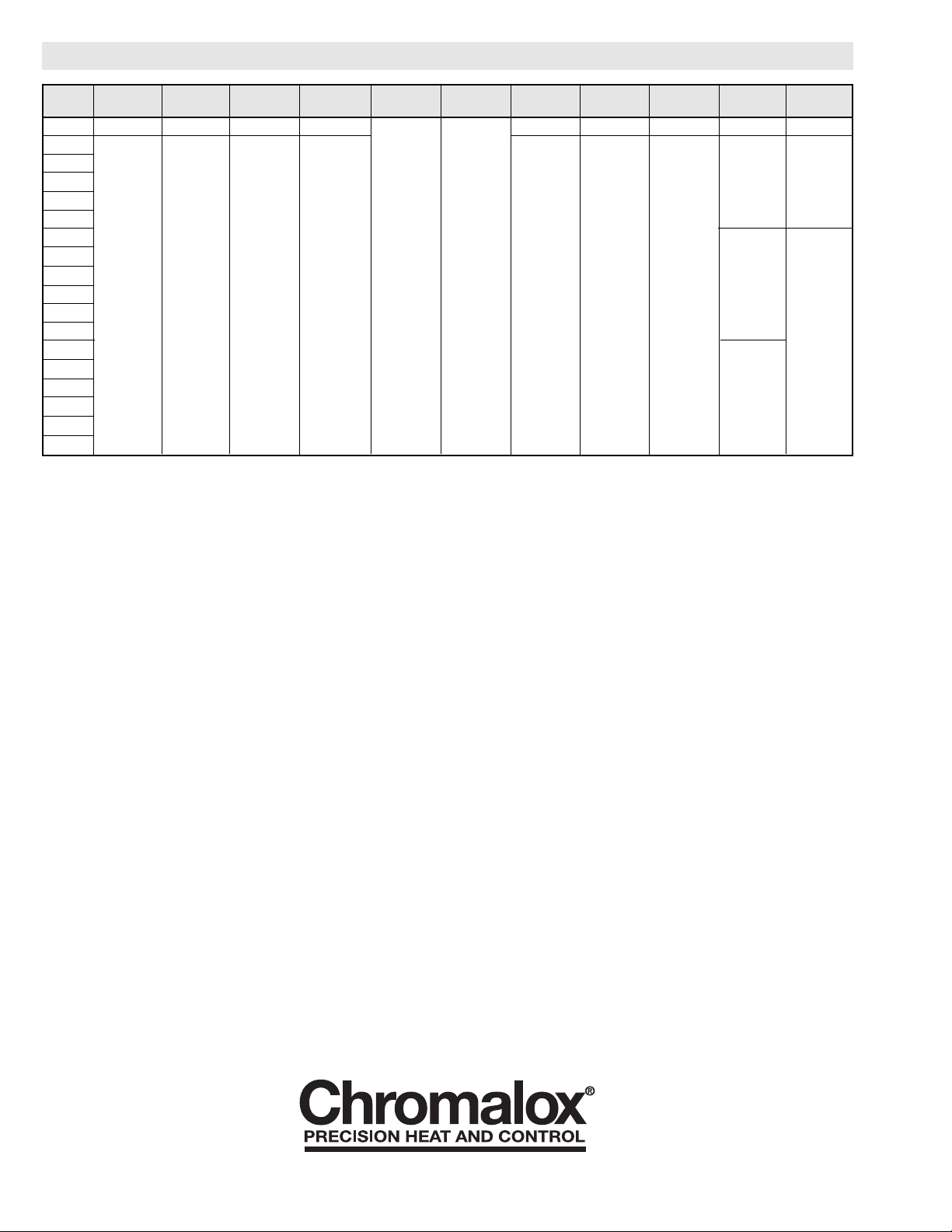
RENEWAL PARTS IDENTIFICATION
Kit Disconnect DS Shaft Cover “U” Shaped Term. Block Term. Block Toggle Toggle Switch Ground Fault Tip Over
Model Switch Gasket Gasket Clamp Cont. Sect. End. Sect. Switch Boot Contactor Sensor Switch
DS-506008 292-303472-007 132-304689-001 132-304879-002 056-304884-004 NA NA NA NA NA
STAR-GF-8
STAR-GF-3
STAR-GF-4 072-121651-062
STAR-GF-7
STAR-GF-6
STAR-TIP-8
STAR-TIP-2
STAR-TIP-3 NA NA NA NA 303-052241-002 303-052241-001 292-046123-001 024-052539-001 072-306110-008 N/A 292-304695-001
STAR-TIP-4
STAR-TIP-7
STAR-TIP-6
STAR-TG-8
STAR-TG-2
STAR-TG-3 072-121651-062
STAR-TG-4
STAR-TG-7
STAR-TG-6
Limited Warranty:
Please refer to the Chromalox limited warranty applicable to this product at
http://www.chromalox.com/customer-service/policies/termsofsale.aspx.
 Loading...