

Page 1
Installation Instructions
DH and DHOC
Electric Duct Heaters
PF503
161-562766-001
1
February 2015
Page 2

Table of Contents
Section Page
General ...............................................................................................................................3
Installation .......................................................................................................................... 3
Mounting ............................................................................................................................6
Wiring ................................................................................................................................10
Operation .........................................................................................................................11
Maintenance ....................................................................................................................11
Heater Bundle Removal and Replacement ................................................................... 11
Replacement Parts .......................................................................................................... 12
Troubleshooting ............................................................................................................... 13
2
Page 3
DH and DHOC Electric Duct Heaters
General
Read and understand all instructions before installing, servicing or operating product. Failure
to do so could result in personal injury or property damage.
These heaters are designed to be installed in either a
horizontal or vertical duct in one of the six positions
shown in figure 12. The heater is constructed with individual metal sheath fintube elements mounted to a
heavy gauge metal terminal box.
Due to the various options and materials available,
check the nameplate attached to the heater terminal
box with the catalog number designation system before installing to insure the heater you received conforms to your specification.
Please read these directions carefully to insure all limitations are properly observed and all wiring and controls are properly installed and connected.
IMPORTANT - Observe at least one complete heating cycle operation before leaving the installation.
FIRE/EXPLOSION HAZARD. This heater is not
intended for use in hazardous atmospheres
where flammable vapors, gases, liquids or
other combustible atmospheres are present as
defined in the National Electrical Code. Failure
to comply can result in personal injury or property damage.
ELECTRIC SHOCK HAZARD. Any installation
involving electric heaters must be performed
by a qualified person and must be effectively grounded in accordance with the National
Electrical Code to eliminate shock hazard.
ELECTRIC SHOCK HAZARD. Disconnect all
power before installing or servicing heater.
Failure to do so could result in personal injury
or property damage. Heater must be installed
or serviced by a qualified person in accordance
with the National Electrical Code, NFPA 70.
Installation
Limitations: Must be in accordance with one of the
following: Standards of the National Fire Protection
Association for the installation of Air Conditioning and
Ventilating Systems of other than Resident Type (Pamphlet 90A) or Residential Type Warm Air Heating and
Air Conditioning Systems (Pamphlet 90B).
NOTE: The minimum distances shown are limitations.
Wherever possible, locate as far away from these limits as practical. In any case, this distance with any required airflow correction must be sufficient to accomplish even air flow at a velocity equal to, at least, the
minimum stated on the heater nameplate.
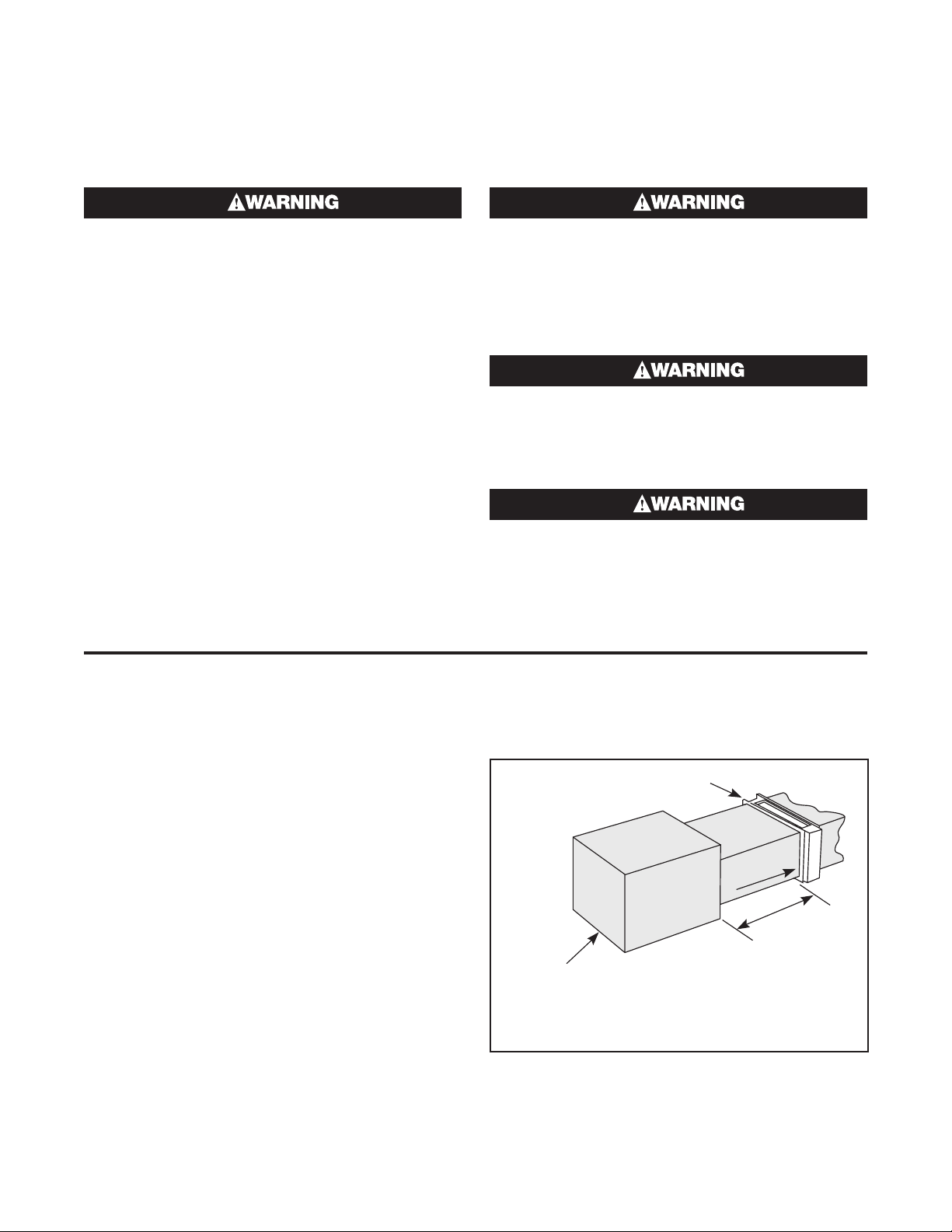
1. Installation near heat pump, central air conditioner,
filters or humidifier. (Refer to Figure 1).
Duct Heater
Air
Flow
4 Ft.
Min.
Heat Pump,
Central Air Conditioner,
Filters or Humidifier
Figure 1
3
Page 4
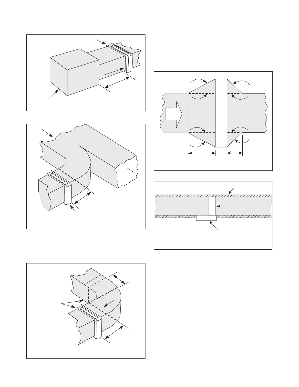
2.
Installation near air handler discharge. (Refer to Fig. 2).
Duct Heater
Air
Flow
5. Installation with duct transitions in some air distribution systems, the duct heater may be considerably larger than the ductwork and the duct area
must be increased by a sheet metal transition. The
slope of the transformation piece on the upstream
side of the equipment is limited to 30° as indicated
in Fig. 5. On the leaving side, the slope should not
be more than 45°.
4 Ft.
Min.
Air Handler
Figure 2
3. Installation in branch duct take-off. (Refer to Fig. 3).
Air Flow
4 Ft. Min. Straight Section
Duct Heater
Figure 3
4.
Installation near turns. (Refer to Fig. 4). If heater must
be installed closer than 4 feet from the downstream
side of a turn, turning vanes must be installed in the
turn. The turning vanes will straighten out the air
flow so it will be uniform over the face of the heater.
2 Ft.
Min.
30"
Air
Flow
Max.
30°
4 Ft. Min.
45°
Duct Heater
45°
Max.
4 Ft. Min.
Figure 5
6.
Do not insulate control or terminal box. (Refer to Fig. 6).
External
Insulation
Top of Duct
Duct Heater
Leave Control
Box Uninsulated
Figure 6
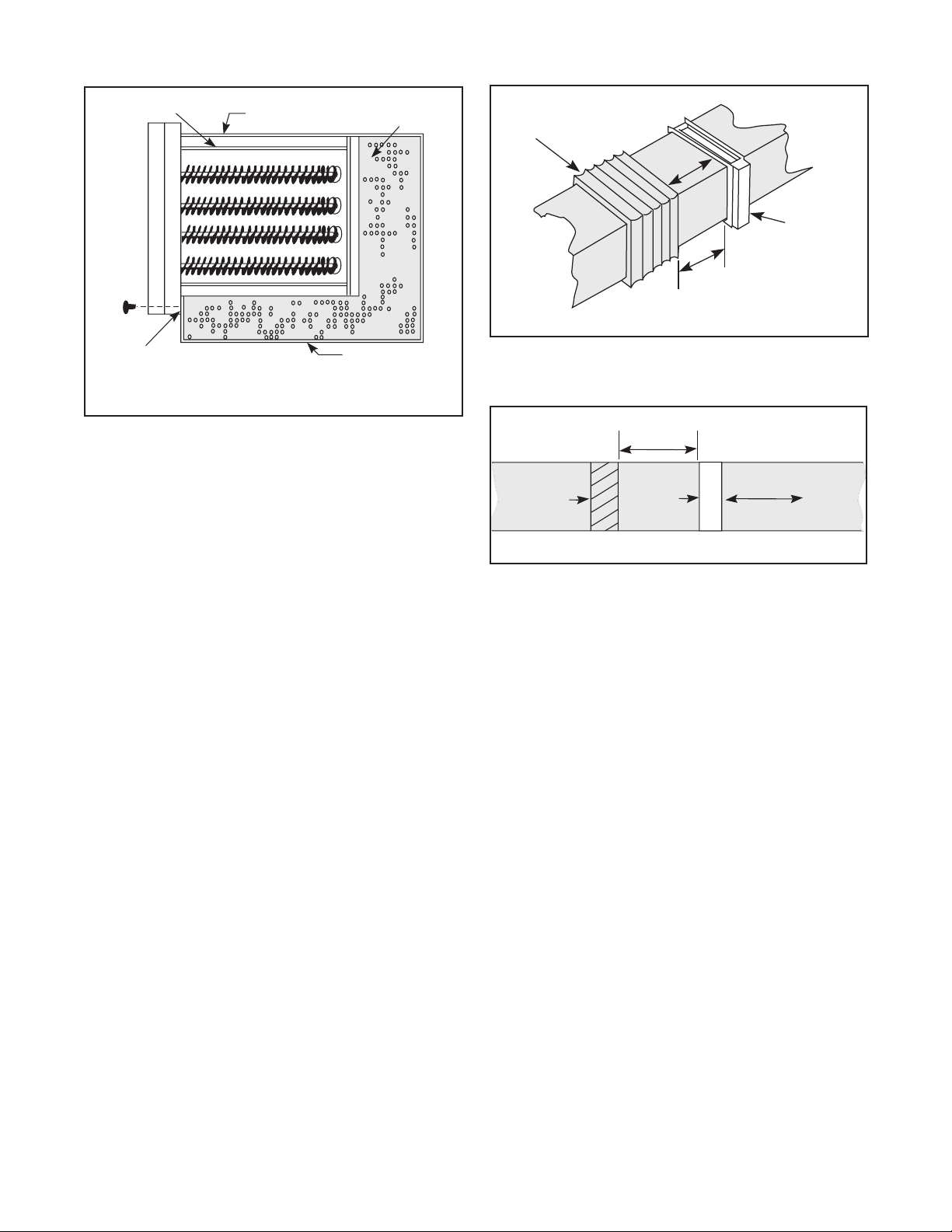
7. Installation in duct larger than heater. For installa-
tion where the duct dimensions exceed the insert
type heater dimensions, the area beyond the heater
dimensions must be filled with wire mesh, expanded or perforated sheet metal of 50% open area as
shown in Figure 7. This will maintain a uniform air
velocity across the face of the duct.
Duct Heater
Here or Here
Air Flow
4 Ft.
Min.
Figure 4
4
Page 5
Inner Baffle
Insert Type
Duct Heater
Perforated Metal
(50% Open Area)
Flexible Duct
(Must be suitable
for 195°F)
Air
Flow
4 Ft.
Min.
Figure 8
Duct Heater
Remove Bracket and
Use Sheetmetal Screws
Thru Same Holes into Duct.
Oversized Duct
Figure 7
8. Installation with flexible duct. Where a duct heater
must be installed near a flexible duct connection,
be certain that a 4’ minimum distance between the
duct heater and the flexible connector exists and
that the connector is suitable for 195°F temperature. (Refer to Fig. 8).
9. Do not install duct heater outdoors. Duct heaters
cannot be installed with rooftop equipment where
they are exposed to the weather.
10.
Installation with dampers or filters. Maintain at least
4’ distance between duct heater and damper, filter
frames, or other similar obstructions. (Refer to Fig. 9).
4 Ft.
Min.
Damper
Duct
Heater
Air Flow
Top of Duct
Figure 9
Clearance: Zero clearance between duct heater and
combustible materials such as wood is permissible.
However, adequate clearance must be provided around
terminal box for proper ventilation and future service accessibility.
5
Page 6

Air Flow
Flow through duct heater must never drop below the
minimum air velocity shown on duct heater nameplate.
If the air handling system includes filters, they must be
cleaned whenever necessary in order to maintain air
flow above the minimum, otherwise poor temperature
control and discomfort will result.
If air flow is poorly distributed within the duct, deflector
vanes must be added to provide correction.
The minimum air velocities shown on the nameplate
are not to be considered average readings. Do not add
various velocities taken across the face of the duct,
find an average value, and compare it to the minimum
velocity shown on the heater nameplate.
The minimum air velocity refers to any point along the
face of the duct heater when checking duct velocities,
no velocity can be below that sown on the heater nameplate (remembering inlet air temperature). Velocities are
best checked with an anemometer, taking numerous
readings along the horizontal and vertical centerline
of the duct heater at the location prior to installation
Example: 500 FT./MIN. Minimum Air Velocity
on Heater Nameplate.
Velocity
Profile
Ft./Min.
RIGHT:
600
500 400x
700 800
600 900
900 600
700 700
600 200x
500 300x
500 Ft./Min.
Minimum
Velocity
Profile
Ft./Min.
WRONG:
200x
400x
9 4500 =
500 Ft./Min
Average
or slightly up stream from the heater after installation.
(Refer to Figure 10). Large ducts will require additional
readings taken at locations in addition to the centerline.
Duct Heater
Air Flow
Incoming Air Temperature: Incoming air temperature
entering the duct heater must not exceed 100°F.
Velocity
Profile
Figure 10
Mounting
Multiple Duct Heaters: Up to six duct heaters may be
combined into a heating bank as shown in Figure 11.
When called for on order, brackets will be furnished for
fastening flange type duct heaters together to form a
bank. Heater will be coded for proper assembly in the
field.
Two to six duct heaters (with flange) may be installed in
a horizontal or vertical duct.
Heaters must be mounted in the position designated
by arrows on the heater frame. (Refer to Figure 12).
The heater terminal box on vertical duct installations
can be located on any side of the duct but for horizontal duct installation the terminal box must be on the
side of the duct.
Figure 11
6
Page 7

Figure 12
Airflow
Left
Airflow
Right
Airflow
Right
Airflow
Left
Horizontal duct with panel
extended in left direction
Airflow
Up
Airflow
Down
Vertical duct with panel extended
in Upward direction
Airflow
Right
Airflow
Left
Horizontal duct with panel extended
in RIGHT direction
Airflow
Up
Airflow
Down
Vertical duct with panel extended
in DOWNWARD direction
Airflow
Left
Airflow
Right
Bottom mount in horizontal duct with
panel extended in LEFT direction
Bottom mount in horizontal duct with
panel extended in RIGHT direction
7
Page 8

Mounting
Mounting Procedure
(Flanged heaters with control box)
1. At heater location, cut out a section of duct, or a
new construction lay out duct work to accommodate dimensions of heater.
2. Form mounting flanges on cut edges of duct as
shown in Figure 13. Omit flange in side when terminal box overhangs.
3. Position heater in duct and attach duct lip to heater
flanges with sheet metal screws.
4. Attach control box to duct with sheet metal screws
through the mounting holes provided inside the
control box.
NOTE: Where necessary, make provision to support
weight of heater. Any part of heater flange may be
drilled for attaching hanger straps or duct.
5. Where necessary, joint between duct and heater
flange may be sealed with silicone gaskets or silicone sealant.
Double
Lip
3/4"
Control
Box
Sheet Metal
Screws
Mounting
Holes
3/4"
W
Figure 13
Self-Adhesive Gasket
Supplied with Heater and
Installed by Customer
Duct
D
W
H
Sheet Metal
Screws
H
Mounting Procedure
(Insert heaters with control box)
NOTE: Insert or slip-in type duct heaters are designed
to be inserted into existing duct and require a rectangular hole of proper size to be cut. The heater frame is
manufactured with a specified duct height (H in figure
14) and a standard depth (D in figure 14). If the frame
does not match the specified dimensions contact a
Chromalox representative.
1. Measure the height and width of the heater frame
and note (H and D per figure 14).
2. The next step is to cut out the rough opening. Cut a
rectangle in the duct with dimensions H x (D - 1.5”).
Remove the sheet metal. (See figure 14A)
3. With the rough opening cut and the sheet metal removed, cut the remaining 3/4 and fold over sides to
create support tabs. (See figure 14A).
4. Attach control box to duct with sheet metal screws
through the mounting holes provided inside the
control box and through the brackets on the top
and bottom of heater.
5. Where necessary, make provision to support weight
of heater and terminal box.
3/4"
Control
Box
Sheet Metal
Screws
Mounting
Holes
Cut 3/4” and fold
over to create tab
Double
Lip
Self-Adhesive Gasket
Supplied with Heater and
Installed by Customer
Duct
Figure 14
D
W
D
H
H
Cut 3/4” and fold
over to create tab
H
W
Cut out and remove
shaded area H x (D-1.5”)
Figure 14a
8
Page 9

Mounting Procedure
(Flanged heaters with compact terminal box)
1. At heater location, cut out a section of duct, or on
new construction lay out duct work to accommodate dimensions of heater.
2. Form mounting flanges on cut edges of duct as
shown in Figure 15.
3. Position heater in duct and attach duct lip to heater
flanges with sheet metal screws.
NOTE: Where necessary, make provision to support
weight of heater. Any part of heater flange may be
drilled for attaching hanger straps or duct.
4. Attach control box to duct with sheet metal screws
through the mounting holes provided inside the
control box.
5. Where necessary, joint between duct and heater
flange may be sealed with silicone gasket or sealant.
Mounting Procedure
(Insert heaters with compact terminal box)
NOTE: Insert or slip-in type duct heaters are designed
to be inserted into existing duct and require a rectangular hole of proper size to be cut. The heater frame is
manufactured with a specified duct height (H in figure
16) and a standard depth (D in figure 16). If the frame
does not match the specified dimensions contact a
Chromalox representative.
1. Measure the height and width of the heater frame
and note (H and D per figure 16).
2. The next step is to cut out the rough opening. Cut a
rectangle in the duct with dimensions H x (D - 1.5”).
Remove the sheet metal. (See figure 16A)
3. With the rough opening cut and the sheet metal removed, cut the remaining 3/4 and fold over sides to
create support tabs. (See figure 16A).
4. Attach control box to duct with sheet metal screws
through the mounting holes provided inside the
control box and through the brackets on the top
and bottom of heater.
5. Where necessary, make provision to support weight
of heater and terminal box.
Double
Lip
3/4"
Sheet Metal
Screws
Mounting
Holes
3/4"
Sheet Metal
Screws
Mounting
Holes
3/4"
Double
Lip
Cut 3/4” and fold
over to create tab
W
Figure 15
Self-Adhesive Gasket
Supplied with Heater and
Installed by Customer
Duct
W
Figure 16
D
Self-Adhesive Gasket
Supplied with Heater and
Installed by Customer
Duct
D
W
H
Sheet Metal
Screws
W
H
H
D
H
Cut 3/4” and fold
over to create tab
H
Cut out and remove
shaded area H x (D-1.5”)
Figure 16a
9
Page 10

Wiring
ELECTRIC SHOCK HAZARD. Disconnect all
power before installing or servicing heater.
Failure to do so could result in personal injury
or property damage. Heater must be installed
or serviced by a qualified person in accordance
with the National Electrical Code, NFPA 70.
ELECTRIC SHOCK HAZARD. Any installation
involving electric heaters must be performed
by a qualified person and must be effectively grounded in accordance with the National
Electrical Code to eliminate shock hazard.
1. Connect heater only to the voltage, frequency and
phase specified on the nameplate.
2. All wiring should be done according to local and
National Electric Codes.
3. Make supply connections to marked heater terminals using wire suitable for 75°C. (Type RH-RW or
equivalent). In addition, the supply wires must be
rated to supply a minimum of 125% of the total amperage load required by the Duct Heater.
4. Connect field wiring to the Duct Heater using the
Wiring Diagram provided with the heater.
5. Conduit attachment to heater:
a. Ensure that conduit size used matches the
knock-out size(s) provided on Duct Heater
b. Run conduit(s) to conduit knock-out(s) on Duct
Heater
c. Remove knock-out(s) with a punch and hammer.
d. Install conduit to knock-out hole.
6. If the heater does not include a main circuit breaker
or a disconnect switch, a remote disconnect must
be provided (see N.E.C. 424.65).
7. Any wiring that is connected to the secondary
(control) wiring of the Duct Heater is required to be
N.E.C. class 1 (see National Electric Code, Article
725).
Wiring Diagram
The appropriate wiring diagram will be supplied with
each heater.
Field Wire/Conduit Sizing (based on 125% of total heater amperage)
1PH 3PH
1.4 2.5 2.9 3.3 4.3 5.0 10.0 14 1/2 1/2 12
1.8 3.1 3.6 4.2 5.4 6.2 12.5 12 1/2 1/2 15
2.5 4.4 5.0 5.8 7.6 8.7 17.5 10 1/2 1/2 21
3.8 6.7 7.7 8.9 11.5 13.3 26.6 8 1/2 3/4 32
4.7 8.1 9.4 10.8 14.1 16.2 32.4 6 3/4 3/4 39
6.1 10.6 12.2 14.1 18.4 21.2 42.4 4 3/4 1 51
7.2 12.5 14.4 16.6 21.6 24.9 49.9 3 1 1 60
8.3 14.4 16.6 19.1 24.9 28.7 57.4 2 1 1-1/4 69
9.4 16.2 18.7 21.6 28.1 32.4 64.8 1 1-1/4 1-1/4 78
10.8 18.7 21.6 24.9 32.4 37.4 74.8 1/0 1-1/4 1-1/2 90
12.6 21.8 25.2 29.1 37.8 43.6 87.3 2/0 1-1/4 1-1/2 105
14.4 25.0 28.8 33.2 43.2 49.9 99.8 3/0 1-1/2 2 120
16.6 28.7 33.1 38.2 49.7 57.4 114.7 4/0 2 2 138
18.4 31.8 36.7 42.4 55.1 63.6 127.2 250 2 2-1/2 153
20.5 35.6 41.0 47.4 61.6 71.1 142.2 300 2 2-1/2 171
22.3 38.7 44.6 51.5 67.0 77.3 154.6 350 2-1/2 2-1/2 186
24.1 41.8 48.2 55.7 72.4 83.6 167.1 400 2-1/2 3 201
27.4 47.4 54.7 63.2 82.1 94.8 189.6 500 2-1/2 3 228
30.2 52.4 60.5 69.8 90.8 104.8 209.5 600 3 3-1/2 252
33.1 57.4 66.2 76.5 99.4 114.7 229.5 700 3 3-1/2 276
35.3 61.2 70.6 81.4 105.9 122.2 244.4 800 3 3-1/2 294
Wire Size
(AWG or
kcmil)
Conduit Size
Heater
Amps120 208 240 277 208 240 480 1ph 3ph
10
Page 11

Operating Instructions
Heater Start-up:
1. Close the duct heater’s door and ensure that the
latch has engaged by pulling on the door. The door
should not open unless a tool is used to disengage
the latch.
2. Turn on the blower or fan for the ductwork that contains the duct heater.
3. Ensure that the Air Velocity on the downstream side
of the duct heater matches the Minimum Air Velocity stamped on the duct heater’s nameplate. The
minimum airflow requirement shall be met at any
point over the face of the heater.
4. Turn Selector Handle on the duct heater to the
“ON” position. -Note: A small amount of smoke will
usually be emitted from the duct heater when first
initialized. This is from dust that has built up on the
elements and is normal and should only last for a
few seconds.
5. Verify that adequate heat is coming from ductwork
vents.
Maintenance
ELECTRIC SHOCK HAZARD. Disconnect all
power before installing or servicing heater.
Failure to do so could result in personal injury
or property damage. Heater must be installed
or serviced by a qualified person in accordance
with the National Electrical Code, NFPA 70.
Heater Shut-Down:
1. With the blower or fan still running, turn the Selector
handle on the duct heater to the “OFF” position.
2. Verify that the air coming out of the ductwork vents
is not heated.
3. Do not turn off the blower or fan until at least 15
minutes after the heater has turned off.
4. Verify that the duct heater outer surfaces have
cooled down to at least 110°F before touching.
5. Disconnect all power to the duct heater before
opening the duct heater’s door.
1. Periodically clean terminals and terminal covers of
dust and corrosion to maintain good electrical connections and to permit rapid heat dissipation. Use
airblast, and be careful to avoid damage to mica
insulation.
2. At least once a year check for loose terminal connections. Tighten as necessary. Torque to 30 in-lbs.
Heater Bundle Removal
& Replacement
ELECTRIC SHOCK HAZARD. Disconnect all
power before installing or servicing heater.
Failure to do so could result in personal injury
or property damage. Heater must be installed
or serviced by a qualified person in accordance
with the National Electrical Code, NFPA 70.
ELECTRIC SHOCK HAZARD. Any installation
involving electric heaters must be performed
by a qualified person and must be effectively grounded in accordance with the National
Electrical Code to eliminate shock hazard.
1. If there is more than one bank of elements on the
heater, drill out rivets from the back side of the duct
heater that are holding the heating bank that is to
be replaced in place.
11
Page 12

2. Remove wiring from terminal pins of heater bank.
3. Remove thermal cutouts if they are attached to the
bank that needs to be replaced.
4. Remove screws around the outside of the heating
bank that hold the heating bank to the housing.
Replacement Parts
Description Part Number Rating
Heating Element Bank Contact sales
303472019 40 amps
Disconnect Switch
Power Fusing Contact sales
Transformer Fusing Contact sales
Contactors
Transformer Contact sales
Air ow switch 051947001
Automatic Reset Thermal Cutout 306600007
Manual Reset Thermal Cutout 306600008
Pilot Light
303472020 60 amps
303472021 80 amps
303472022 100 amps
306110002 24 V
306110008 120 V
304688001 24 V
304688002 120 V
12
Page 13

Duct Heater Troubleshooting Guide
Problem Causes Solution
Won’t Power On
(no heat)
Not Enough
Heat
Too Much Heat
Field power wires not
connected properly
Fuse(s) have blown or
breaker has tripped
Automatic Reset Cutout
has tripped
Manual Reset Cutout has
tripped
Air Flow Switch has
tripped
Wires have shorted out Shut down the heater per the Heater Shut Down section of the In-
Loose or unconnected
internal wires
Incorrect Voltage Check the rated voltage for the heater provided on the nameplate.
Fuse(s) have blown Check resistance of fuses using a Multimeter to ensure continuity.
Failed Element(s) Shut down the heater per the Heater Shut Down section of the In-
Loose or unconnected
wire terminals
Incorrect Voltage Check the rated voltage for the heater provided on the nameplate.
Improper sizing (kw) Verify that the heater KW provided is adequate for the applica-
Incorrect Voltage Check the rated voltage for the heater provided on the nameplate.
Connect wires per the Wiring section of the Installation & Operating Manual (IOM)
Check resistance of fuses using a Multimeter to ensure continuity.
Replace any blown fuses.
Wait for 30 minutes. The Automatic Cutout should reset and the
heater should begin working again. If not, disconnect wires from
the cutout and use a Multimeter to test for continuity across the
cutout.
Shut down the heater per the Heater Shut Down section of the
Installation & Operating Manual. Open the terminal box and push
the reset button on the manual reset (near the label "PUSH TO
RESET") and start up the heater per the Heater Startup section
of the Installation & Operating Manual. If the heater still does not
function, disconnect wires from the cutout and use a Multimeter
to test for continuity across the cutout. If there is still no continuity
after pushing the button, the cutout needs to be replaced.
Ensure that adequate flow is being provided to the heater per the
Air Velocity requirements stamped on the Nameplate.
stallation & Operating Manual. Open the terminal box and check
for each wire for continuity.
Shut down the heater per the Heater Shut Down section of the Installation & Operating Manual. Open the terminal box and check
wire terminals for proper connection.
Check supply voltage & verify that it matches the nameplate.
Replace any blown fuses.
stallation & Operating Manual. Open the terminal box and use an
ohmmeter to check for resistance across each element. All coils
should have the same resistance. If the heating element is broken
there will generally be either zero or infinite resistance. Replace
any heating banks with broken coils.
Shut down the heater per the Heater Shut Down section of the Installation & Operating Manual. Open the terminal box and check
wire terminals for proper connection.
Check supply voltage & verify that it matches the nameplate.
tion. Ensure that the blower output, when measured downstream
of the duct heater, matches the Air Velocity requirement that is
stamped on the nameplate.
Check supply voltage & verify that it matches the nameplate.
13
Page 14

Problem Causes Solution
Contactor
Chatter
Terminals
Heating Up
Pilot Lights
don’t turn on
Incorrect Control Voltage
Input
Incorrect wire size to
heater
Loose Wiring Connection Tighten wire connections on all terminals.
Light bulb burnt out Replace pilot light
Loose Wiring Connection Check wire connections on all control circuit terminations.
Check the rated control circuit voltage for the heater provided
on the nameplate. Check supply control voltage & verify that it
matches the nameplate.
Check supply wiring size. Wiring sizing should conform to N.E.C.
424.3(b).
© 2015 Chromalox, Inc.
Limited Warranty:
Please refer to the Chromalox limited warranty applicable to this product at
http://www.chromalox.com/customer-service/policies/termsofsale.aspx.
Chromalox, Inc.
2150 N. Rulon White Blvd.
Odgen, UT 84404
1-800-368-2493
www.chromalox.com
14
 Loading...