

Page 1
CTF Single Phase Advanced SCR
Top view
Top view
of line voltage
)
Input control signal (+)
(GND)
5
Power Controller Quick Start Manual
0037-75558 (PK536)
This manual is intended to be a quick reference guide for basic installation requirements and an overview of the connections, wiring considerations, and general specifications for the CTF Advanced SCR Power Controller. For complete installation,
operation, programming and configuration, please refer to the following manuals:
PK533 CTF Hardware Instruction Manual; PK534 CTF & CTF-XTRA Controller Programming Manual; PK537 C-PWR Configuration Software Manual. The most current
revisions may be found on the Chromalox website: www.chromalox.com.
1. IMPORTANT SAFEGUARDS
ELECTRIC SHOCK HAZARD: Read and understand all instructions before
installing, servicing or operating this controller. Failure to do so could
result in equipment or property damage as well as personal injury and
even death.
HIGH VOLTAGE is used in the operation of this equipment; DEATH ON
CONTACT may result if personnel fail to observe safety precautions.
Learn the areas containing high-voltage connections when installing or
operating this equipment.
Be careful not to contact high-voltage connections when installing or
operating this equipment. Before working inside the equipment, turn
power off and ground all points of high potential before touching them.
ELECTRIC SHOCK HAZARD: Any installation involving control equipment must be performed by a qualified person and must be effectively
grounded in accordance with the National Electrical Code or local governing electrical code/authority, to eliminate shock hazard.
The owner/installer must provide all necessary safety and protection
devices and follow all current electrical wiring standards and regulations. Failure to do so may compromise the integrity of the controller
and/or cause product failure resulting in a safety risk to operational and
service personnel.
This controller utilizes a heat sink which is designed to cool the unit
during operation. Under no circumstance should air flow around the
controller be compromised in any way. Failure to do so may result in the
overheating of the controller, product failure, product temperatures and
even fire.
During continuous operation, the heat sink can reach very high temperatures, and keeps a high temperature even after the unit is turned
off due to its high thermal inertia.
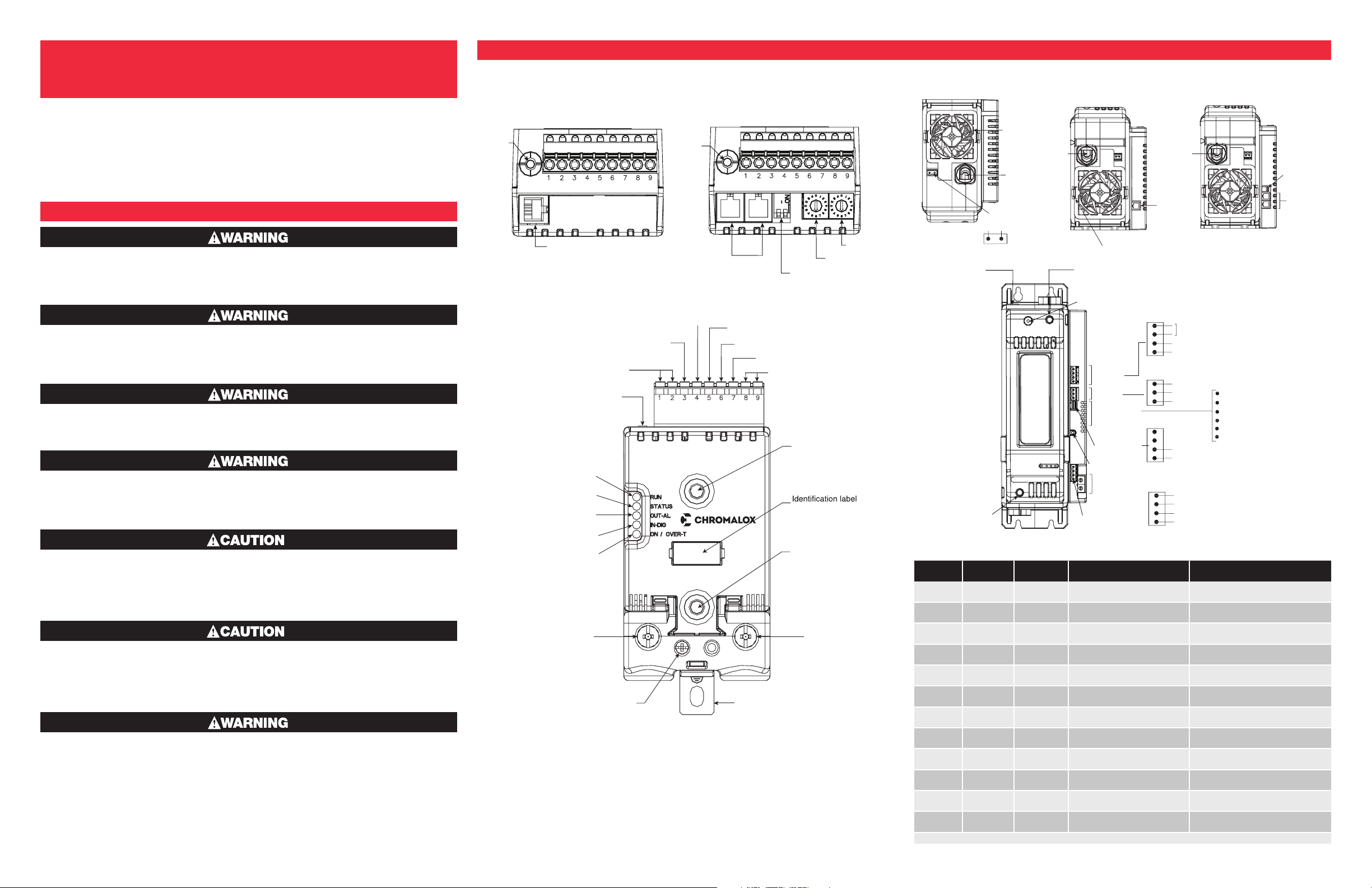
2. INSTALLATION
Input & Output Connections: CTF 25 – 120 Amp Models Input & Output Connections: CTF 150 – 250 Amp Models
WITHOUT Modbus Option
Key HB
J2
TTL port for
Port Configuration
Master/Slave connection
Alarm output
(solid state relay - HB option)
Green Led (RUN)
Yellow Led (STATUS)
Red Led (Alarm output HB)
Yellow Led (Status digital input)
Led: Green = SCR ON
Yellow = Te mperature OVER
1/L1
LINE connection
Reference connection
Key HB
Syncronous output for
Key HB
3/L2
WITH Modbus Option
J3, J4
RJ10 connectors
RS485 serial line
Modbus
Potentiometer output power supply (+5Vdc
Digital input (PWM input)
Earth Ground
Switch for
serial line
Power supply terminal 24Vac/Vdc
J1
Power supply /control
connector
Fixing screw
at heatsink
Fixing screw
at heatsink
Address x 10
2/T1
LOAD connection
Address x 1
Installation Wiring Note:
Use the extra rapid fuses as indicated in the CTF Hardware Instruction Manual PK533,
according to the wiring schematic examples and controller rating. Additionally, the
applications with solid state units require a safety automatic switch to disengage the
load power line during certain alarm events.
Top View
Line voltage
reference
connection
Line Voltage
Connector
2/T1 Load
Connection
Bottom View Without
Modbus RS485 Option
Fan
Protection
Grill
1/L1
Line
Connection
J8
3/L2
n.c.
J8
2/T1
Load
Conn.
Fan Protection Grill
Line Connection
1/L1
Front Cover
Fastener (Fuse Access)
Outputs
Supply
Status LEDs
Digital Input
Key HB
Address Rotary
Switch
(Optional)
Analog Control
Input Connector
J5
Config.
TTL Port
J1
J2
J3
J4
Bottom View WITH
Modbus RS485 Option
2/T1
Load
Conn.
HB OUT Switch (Optional)
OUT Master (7 V)
GND
24 Vac/dc
24 Vac/dc
Earth
n.c.
n.c.
+ INDIG (PWM input)
GND
OUT +5V (Potentiometer)
+ IN
SHUNT – mA
GND
RUN ...................................(Green)
STATUS .............................(Yellow)
ALARM HB ......................(Red)
DIGITAL INPUT STATUS (Yellow)
ON SCR............................(Green)
OVER Temperature........... (Yellow)
Recommended Wire Gauges
CTF Current
Level Terminal Cable Wire Wire Terminal Tightening Torque / Tool
25A 1/L1, 2/T1, PE
40A 1/L1, 2/T1, PE
50A 1/L1, 2/T1, PE
60A 1/L1, 2/T1, PE
75A 1/L1, 2/T1, PE
90A 1/L1, 2/T1, PE
120A 1/L1, 2/T1, PE
-
150A 1/L1, 2/T1
200A 1/L1, 2/T1
250A 1/L1, 2/T1
-
NOTE: Cables must be Copper “Stranded Wire” or “Compact-Stranded Wire” type with max. operating temp. 60/75°C
3/L2
(Ref. Vline)
3/L2
(Ref. Vline)
2
4 mm
10 AWG
2
10 mm
7 AWG
2
10 mm
7 AWG
2
16 mm
5 AWG
2
25 mm
3 AWG
2
35 mm
2 AWG
2
50 mm
1/0 AWG
0.25 ...2.5 mm
23...14 AWG
2
70 mm
2/0 AWG
2
95 mm
4/0 AWG
2
120 mm
250 KCMIL
0.25 ...2.5 mm
23...14 AWG
Wire terminal / Eye D. 6mm 2.5 Nm / Phillips screwdriver PH2 - PH3
Wire terminal / Eye D. 6mm 2.5 Nm / Phillips screwdriver PH2 - PH3
Wire terminal / Eye D. 6mm 2.5 Nm / Phillips screwdriver PH2 - PH3
Wire terminal / Eye D. 6mm 2.5 Nm / Phillips screwdriver PH2 - PH3
Wire terminal / Eye D. 6mm 2.5 Nm / Phillips screwdriver PH2 - PH3
Wire terminal / Eye D. 6mm 2.5 Nm / Phillips screwdriver PH2 - PH3
Wire terminal / Eye D. 6mm 2.5 Nm / Phillips screwdriver PH2 - PH3
2
2
Wire terminal tip
Wire stripped for 25 mm or with
crimped pre-insulated terminal tube
Wire stripped for 25 mm or with
crimped pre-insulated terminal tube
Wire stripped for 25 mm 6 Nm / No. 6 hex head wrench
Wire stripped for 8 mm or with tag
terminal
0.5 ...0.6 Nm / Screwdriver blade 0.6 x
3.5 mm
6 Nm / No. 6 hex head wrench
6 Nm / No. 6 hex head wrench
0.5 ...0.6 Nm / Flat-head screwdriver tip
0.6 x 3.5 mm
Dip Switch
serial line
J6, J7
RJ10
connector
serial RS48
Modbus
Page 2
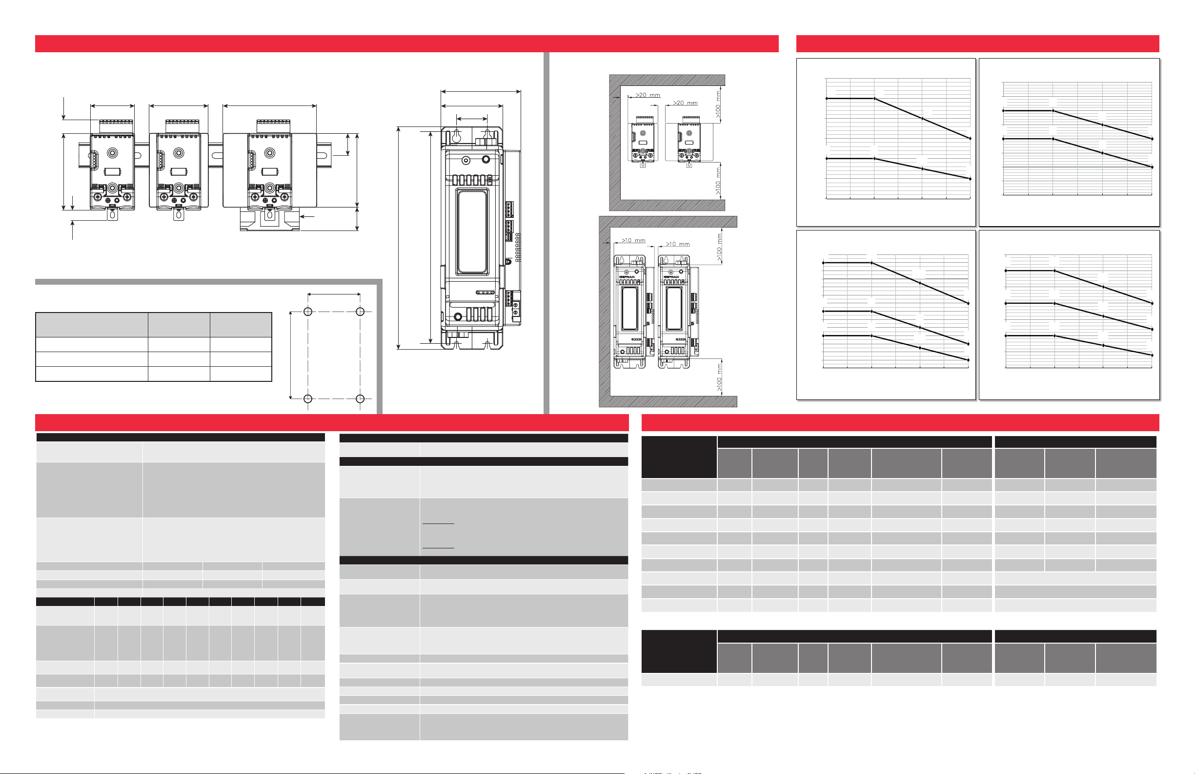
3. INSTALLATION CONSIDERATIONS: DIMENSIONS & WEIGHTS, MOUNTING & SPACING REQUIREMENTS 4. DERATING CURVES
(104)
Dimensions are in Inches (mm)
W
L
LOAD, FIRING, DIAGNOSTICS & RATINGS
CATEGORY OF USE
(Tab. 2 EN60947-4-3)
AC 51 resistive or low inductance loads
AC 55b infrared lamps
AC 56a: transformer loads
Trigger Mode
PA - Load management by adjusting the firing angle (only
configuration single-phase or delta open)
ZC - Zero Crossing with constant cycle time (settable in range
1-200sec)
BF - Burst Firing, or D.O.T. with variable cycle time optimized min.
HSC - Half Single Cycle corresponds to Burst Firing that includes ON
and OFF half-cycles.
Useful for reducing flicker with short-wave IR loads (applied only to
single-phase resistive or 3-phase 6-wire open delta loads).
Feedback Mode
V, V
2
: Voltage feedback proportional to RMS voltage value on load
(useful to compensate possible variations in line voltage).
I, I
2
:
Current feedback: bound to RMS current value on load to com-
pensate variations in line voltage and/or variations in load impedance.
P: Power feedback: proportional to real power value on load (useful
to keep constant values of electrical power assigned regardless of
load impedance or line voltage variations).
Max rated voltage 480 Vac 600 Vac 690 Vac
Work voltage range 90 - 530 Vac 90 - 660 Vac 90 - 760V ac
Non-repetitive voltage 1200 Vp 1600 Vp 1600 Vp
Rated Frequency 50/60Hz Auto-Synchronization
CTF MODEL CTF-025 CTF-040 CTF-050 CTF-060 CTF-075 CTF-090 CTF-120 CTF-150 CTF-200 CTF-250
Rated Current, AC51 AC55b Resistive Load
(@ 40˚C contin. service)
25A 40A 50A 60A 75A 90A 120A 150A 200A 250A
Rated current AC56A
permitted trigger
modes: ZC, BF/DOT
with DT (Delay Trigger),
PA with softstart
(@ Tamb = 40 °C)
20A 32A 40A 50A 60A 75A 100A 125A 160A 200A
Maximum Surge Current
(t = 10 ms) A
400A 520A 520A 1150A 1150A 1500A 1500A 5000A 8000A 8000A
Maximum I
2
t for fusing
(blowout) A
2
s
450 1,800 1,800 6,600 6,600 11,200 11,200 125,000 320,000 320,000
Critical dV/dt Off-state
(minimum)
1,000V/µs
Nom. Impulse Voltage 4KV
Nominal SCCR 5KA
FUNCTION
Diagnostics
Detection of shorted load circuit,
absence of line voltage, HB alarm (partial break of load)
OPTIONS
Options
- Timed Soft-Start firing ramp, with or without peak current control
- Soft-Start firing ramp (specific for infrared lamps)
- Timed shut-off ramp
- Limitation of RMS current in load
- 0-90° Delay-Triggering for firing inductive loads in ZC and BF/DOT modes.
Diagnostic
- SCR in short circuit (presence of current with OFF control)
- Absence of SCR current when under load.
- Overtemperature alarm
Current read
• HB alarm: interrupted or partially interrupted load
• Automatic calibration of HB alarm setpoint starting from current value in load
• Alarm for load in short circuit or overcurrent
Voltage read
• No line voltage
GENERAL DATA
Power Supply
CTF 25-120 A: 24 Vac 50-60 Hz / Vdc ± 25%, max 3 VA
CTF 150-250 A: 24 Vac 50-60 Hz / Vdc ± 25%, max 11 VA
Power supply for external fan
(only for CTF120A model)
24 Vdc ± 10%, max 200mA
Signals
5 leds: RUN: run state of CPU
STATUS: operating state
ALARM: state of alarm output
DIGITAL INPUT: state of digital inputs
ON / OVER-TEMP.: state of SCR power / Alarm for overheating
Load Type and Connection
Single phase load
Independent single-phase load in open delta
3-phase load
3-phase load (star without neutral or closed triangle) with 2-leg control
Protection IP20
Ambient Temperature
0 to 50˚C (32 to 122˚F) (Per EN 60947-4-3 § 7.1.1: Average Temperature over 24
hour period shal not exceed 35˚C (95˚F)
Storage Temperature -20˚C to 70˚C (-4˚F to 158˚F)
Relative Humidity 20…85% RH non-condensing
Ambient Conditions for use Indoor use, altitude up to 2000m
Installation DIN Rail EN50022 or panel with screws
Installation Requirements
Installation category II, pollution level 2, double isolation (only for model >120A):
- Max. temperature of air surrounding device 40°C; for temperature >40°C refer
at derating curves
- Device type: “UL Open Type”
25 25
22.5
20
40
40
35
30
15
20
25
30
35
40
45
0 40 45 50
;7* ;7*
99*
97*97* 97*
:9*
:7*
30
35
40
45
50
55
60
65
70
0 40 45 50
200 200
180
160
250 250
225
200
150 150
135
120
100
125
150
175
200
225
250
275
0 40 45 50
90 90
80
70
120 120
107.5
95
75 75
67.5
60
55
60
65
70
75
80
85
90
95
100
105
110
115
120
125
0 40 45 50
Current (Amps)
Enclosure / Ambient Temperature ˚C
CTF-025 & CTF-040
Current (Amps)
Enclosure / Ambient Temperature ˚C
CTF-050 & CTF-060
Current (Amps)
Enclosure / Ambient Temperature ˚C
CTF-150, CTF-200, CTF-250
Current (Amps)
Enclosure / Ambient Temperature ˚C
CTF-75, CTF-90, CTF-120
CTF 25 A
CTF 40 A
CTF 50 A (Without Fan)
CTF 60 A (Without Fan)
CTF 75 A (Without Fan)
CTF 90 A (Without Fan)
CTF 120 A (With Fan)
2.4 (60.1)
3.1 (80)
0.7 (18.5)
4.1
0.5 (14.0)
Depth: 5.6 (143)
Depth: 5.6 (143)
Weight: 1.8 lbs (810 g)
Weight: 2.1 lbs (970 g)
Weight: 2.9 lbs (1,300 g)
Weight: 3.3 lbs (1,500 g)
Rear Panel Mounting Template
Model
In. (mm)
CTF 25-40-50-60A 4.4 (112) 1.7 (44)
CTF 75-90-120A 4.4 (112) 4.4 (113)
CTF 150-200-250A 11.3 (287) 1.7 (42)
Length
Width
In. (mm)
5 (127)
Depth: 5.6 (143)
1.2 (30)
Fan
3.9
(100)
1.3
(32)
11.9
(302)
CTF 150 A, 200 A, 250 A
11.3
(287.4)
Depth: 6.7 (170.4)
Weight: 5.7 lb. (2,600 g)
Minimum Spacing Requirements
4.3 (108.3)
3.3 (84)
1.7 (42)
5. GENERAL TECHNICAL DATA & SPECIFICATIONS 6. FUSES & FUSE HOLDERS
2
I
CTF Model
480 & 600 Vac
unless otherwise
specified
Fuse
Rating,
Amps I
2
t
t Extra Rapid Fuses Fuse Holder
Power
Dissi-
pation Fuse Size
Manufacturer’s
Model Code Part No. Part No.
Fuse Holder
Rating (UL)
Fuse Holder
Rating (IEC)
CTF-25 25A 390 A²s 6W 10x38 FWC25A10F 0024-07815 0024-12124 30A@600V 32A@690V
CTF-40 50A 1,600 A²s 9.5W 22x58 FWP50A22F 0024-07816 0024-12199 100A@600V 125A@690V
CTF-50 50A 1,600 A²s 9.5W 22x58 FWP50A22F 0024-07816 0024-12199 100A@600V 125A@690V
CTF-60 63A 3,080 A²s 11W 22x58 FWP63A22F 0024-07817 0024-12199 100A@600V 125A@690V
CTF-75 80A 6,600 A²s 14W 22x58 FWP80A22F 0024-07818 0024-12199 100A@600V 125A@690V
CTF-90 125A 6,950 A²s 25W 100x51x30 170M2665 0024-07819 0024-12029 400A@600V *not CE-marked
CTF-120 125A 6,950 A²s 25W 100x51x30 170M2665 0024-07819 0024-12029 400A@600V *not CE-marked
CTF-150 200A 31,500 A²s 19W FUS-200S DN000UB69V200 0024-07820 Fuse is mounted internal to the controller
CTF-200/250 450A 196,000 A²s 17W FUS-450S DN00UB60V450L 0024-07821 Fuse is mounted internal to the controller
CTF-200/250 @690V 400A 150,000 A²s 20W FUS-400S DN00UB69V400L 0024-07822 Fuse is mounted internal to the controller
Instrument Fuse Fuse Holder
Power
Dissi-
2
t
pation
Fuse Size
Manufacturer’s
Model Code Part No. Part No.
Fuse Holder
Rating (UL)
Fuse Holder
Rating (IEC)
CTF Model
Fuse
Rating,
Amps I
All Models 1A N/A N/A 10x38 KTK-1 0024-01113 0024-12124 30A@600V 32A@690V
PK536
0037-75558
August 2015
© 2016 Chromalox, Inc.
 Loading...