

Page 1
Thermal Devices, Inc. Mount Airy, Maryland USA www.thermaldevices.com
y
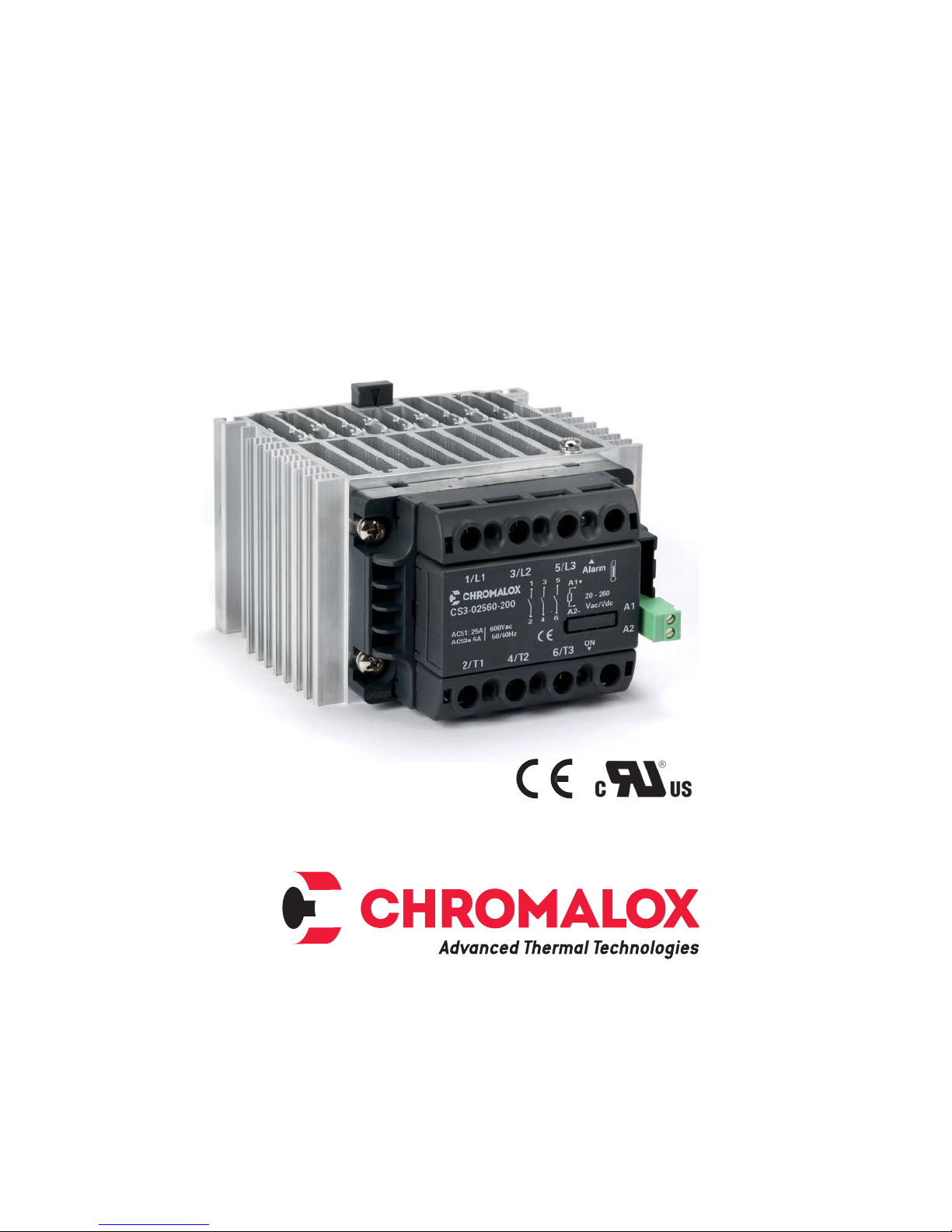
Installation Instructions
CS3 Three Phase
Solid State Relay
1
Thermal Devices, Inc. Mount Air
PK522-2
0037-75550
August 2015
, Maryland USA www.thermaldevices.com
Page 2

Thermal Devices, Inc. Mount Airy, Maryland USA www.thermaldevices.com
y
Important Safeguards
HIGH VOLTAGE is used in the operation of this
equipment; DEATH ON CONTACT may result if
personnel fail to observe safety precautions.
Learn the areas containing high-voltage connections when installing or operating this
equipment.
Be careful not to contact high-voltage connections when installing or operating this equipment.
Before working inside the equipment, turn
power off and ground all points of high potential before touching them.
ELECTRIC SHOCK HAZARD: Any installation involving control equipment must be performed
by a qualified person and must be effectively grounded in accordance with the National
Electrical Code to eliminate shock hazard.
Thermal Devices, Inc. Mount Air
2
, Maryland USA www.thermaldevices.com
Page 3
Thermal Devices, Inc. Mount Airy, Maryland USA www.thermaldevices.com
y
CS3 Three-Phase Solid State Relay
General
The CS3 Series of solid state relays are an ideal, low
cost power control solution for switching resistive
3-phase loads found applications in such as furnaces,
ovens, heat treating, injection molding, thermoforming,
press platens, commercial food equipment, semiconductor, lighting and drying, just to name a few.
Installation and Operation
The owner/installer must provide all necessary
safety and protection devices and follow all
current electrical wiring standards and regulations. Failure to do so may compromise the integrity of the controller and / or cause product
failure resulting in a safety risk to operational
and service personnel.
This controller utilizes a heat sink which is designed to cool the unit during operation. Under no circumstance should air flow around the
controller be compromised in any way. Failure
to do so may result in the overheating of the
controller, product failure, product temperatures and even fire.
The CS3 Series power controllers feature:
• Rugged, industrial design & touch-safe exterior
• Conservative, continuous service ratings at 40˚C
• Up to 3 x 55 Amps and up to 600 VAC
• AC and DC Voltage command signals
• Zero cross firing
• Easy terminal access via removable covers
• Integrated heat sink and fan
• SCR thermal protection with LED indication
• Optional over temperature alarm
• Optional load / line interrupt alarm
• USA & Canadian UL component recognition
• CE conformity
To ensure proper performance, maximum safety and
reliability, it is essential to install the unit correctly. This
includes proper mounting, spacing, hardware and wiring. See below:
1. Maximum surrounding air temperature is 40°C in
“Open Type Equipment” which is suitable for use in
pollution degree 2.
2. Install the unit vertically (max 10° inclination from
vertical axis).
3. Spacing:
- Minimum vertical distance between unit and
panel wall: 3.94” (100 mm)
- Minimum horizontal distance between unit and
panel wall: .79” (20 mm)
- Minimum vertical distance between adjacent
power control units: 11.81” (300 mm)
- Minimum horizontal distance between adjacent
power control units: .79” (20 mm)
During continuous operation, the heat sink can
reach very high temperatures, and keeps a
high temperature even after the unit is turned
off due to its high thermal inertia.
Higher voltages may be present. DO NOT work
on the power section without first cutting out
electrical power to the panel. Failure to do so
may cause serious injury or death.
Thermal Devices, Inc. Mount Air
3
, Maryland USA www.thermaldevices.com
Page 4

Thermal Devices, Inc. Mount Airy, Maryland USA www.thermaldevices.com
y
CS3 25A CS3 40A / CS3 55A
5” (127) 5” (127)
8
1.18” (30)
3.15” (80) 8
1/L1 3/L2 5/L3
CS3-02548-110
AC51: 25A
AC53a: 5A
2/T1 4/T2 6/T3
2.4lb (1100 g)
Depth:
- Models CS3-xxxxx-1xx: 5.9” (150)
- Models CS3-xxxxx-2xx: 6.2” (158)
Figure 1
CS3 with VDV Control Signal Input
1/L1 3/L2 5/L3
CS3-04060-111
fan: 230 VAC
AC51: 40A
600 VAC
AC53a: 8A
50/60 Hz
2/T1 4/T2 6/T3
Alarm
1 3 5 A1+
5-32 Vdc
2 4 6 A2-
On
L1 L2 L3 A1+
T1 T2 T3 A2-
Alarm
On
B1
B2
A1
A2
B1
B2
A1
A2
1/L1 3/L2 5/L3
CS3-04060-112
AC51: 40A 600V ac
AC53a: 8A 50/60Hz
L1 L2 L3 A1+
T1 T2 T3 A2-
2/T1 4/T2 6/T3
3.0 lb (1350 g)
Alarm
On
B1
B2
A1
A2
1.18” (30)
3.94 (100)1.97” (50) Max
Label Connection / Indication
L1, L2, L3 Line 1, Line 2, Line 3 VAC Input
T1, T2, T3 Load 1, Load 2, Load 3 VAC Output
A1 (+) VDV Control Signal Input
A2 (-) VDV Control Signal Input
B1 Alarm Output (option)
B2 Alarm Output (option)
ON Red LED - Command Signal Indication
Alarm Yellow LED - Over Temp. Indication
GND Earth Ground
(Not shown, varies by model)
CS3 with VAC Control Signal Input
1/L1 3/L2 5/L3
CS3-04060-221
fan: 230 VAC
AC51: 40A
600 VAC
AC53a: 8A
50/60 Hz
Out
AI
2/T1 4/T2 6/T3
Alarm
1 3 5 A1+
2 4 6 A2-
On
Thermal Devices, Inc. Mount Air
20-260
VAC/VDC
B1
B2
nc
nc
A1
A2
Label Connection / Indication
L1, L2, L3 Line 1, Line 2, Line 3 VAC Input
T1, T2, T3 Load 1, Load 2, Load 3 VAC Output
A1, A2 AC Control Signal Input
B1 Alarm Output (option)
B2 Alarm Output (option)
ON Red LED - Command Signal Indication
Alarm Yellow LED - Over Temp. Indication
OUT-AL
GND Earth Ground
4
Red LED - Load/Line Interrupt Alarm
(Alarm Code 2 Only)
(Not shown, varies by model)
, Maryland USA www.thermaldevices.com
Page 5

Thermal Devices, Inc. Mount Airy, Maryland USA www.thermaldevices.com
y
Wiring Diagrams
Wiring CS3 with VDC Control Signal Input
Phase L1
Phase L2
Phase L3
Neutral
Ground
F1 F2 F3
Optional Over Temperature
Alarm Output Feature
LOAD LOAD
RR
R
RRR
Load
RR
R
1/L1 3/L2 5/L3
CS3-04060-111
fan: 230 VAC
AC51: 40A
600 VAC
AC53a: 8A
50/60 Hz
2/T1 4/T2 6/T3
Wiring CS3 with VAC/VDC Control Signal Input (Code 2)
Phase L1
Phase L2
Phase L3
Neutral
Ground
F1 F2 F3
13 5 A1+
2 4 6 A2-
Alarm
5-32 Vdc
On
B1
B2
A1
A2
5-32 VDC
Control
Signal
Output
Temperature / Process
Controller
Optional Over Temperature
Alarm Output Feature
LOAD LOAD
Load
RR
R
RRR
Thermal Devices, Inc. Mount Air
1/L1 3/L2 5/L3
RR
R
CS3-04060-221
fan: 230 VAC
AC51: 40A
600 VAC
AC53a: 8A
50/60 Hz
Out
AI
2/T1 4/T2 6/T3
1 3 5 A1+
2 4 6 A2-
20-260
VAC/VDC
On
B1
B2
nc
nc
A1
A2
20 - 260 VAC/DC
Control Signal Output
Temperature / Process
Controller
5
, Maryland USA www.thermaldevices.com
Page 6

Thermal Devices, Inc. Mount Airy, Maryland USA www.thermaldevices.com
y
Specifications
General
Category of use: ......................................AC51, AC53a
Switching Mode: .........................................Zero Cross
Input/Output Isolation Voltage: ............4,000 VAC RMS
Operational Voltage Range
• 480VAC models: ................................. 24 - 530 VAC
• 600VAC models: ................................. 24 - 660 VAC
Nominal Frequency: ..................................... 50 - 60 Hz
Non-repetitive peak voltage
• 480VAC models: ......................................... 1200 Vp
• 600VAC models: ......................................... 1200 Vp
Zero Voltage Turn-on: .......................................... ≤ 20V
Activation time: ............................................= 1/2 cycle
Deactivation time: ........................................= 1/2 cycle
Potential drop at rated current: ................ = < 1.4 Vrms
Power factor ............................................................ = 1
IP20 Protection
Outputs
Specification CS3-025 CS3-040 CS3-055
Rated Current (@ 40˚C continuous service)
Maximum Surge Current (t=20 ms) 400 A 600 A 1,150 A
2
Maximum I
Critical dV/dt Off-state (minimum) 1,000 V/μs
Off-state Leakage Current (@ Rated Voltage) < 3 mA
t for fusing (blowout) 645 A2s 1,010 A2s 6,600 A2s
Inputs
VDV Input (Type “1”)
Control voltage: ...........................................5 - 32 VDC
Maximum input: ......< 18 mA @5 VDV to 22 mA @ 32 V
Maximum reverse voltage: ............................... 36 VDC
Activation voltage: ........................................ > 4.5 VDC
Deactivation voltage: ....................................... < 3 VDC
VAC Input (Type “2”)
Control voltage: ................................. 20 - 260 VAC/DC
Activation voltage: ................................... > 15 VAC/DC
Deactivation voltage: ................................. < 6 VAC/DC
Current draw: ................... ≤ 8 mAac/dc @ 260 VAC/DC
AC51 AC53 AC51 AC53 AC51 AC53
3 X 25A 3 X 5A 3 X 40A 3 X 8A 3 X 55A 3 X 15A
Integrated Thermal Protection
The SSR temperature is constantly monitored. If the
maximum temperature limit (230°F/110°C) is exceeded, current to the load is interrupted and the YELLOW
over-temperature condition LED illuminates.
Alarm Output Option
The Alarm Output is a Solid State Switch (isolated
contact) which controls a connected device during an
alarm event, such as a horn or light.
• Requires external 24 VAC/DC power supply
• Ratings: Imax = 150 mA
Vmax = 32 VAC/DC
Z close < 15 ȍ (impedance)
For Models with 24 VDV Input Control Signal
The alarm output function closes the isolated solid
state output switch when it detects the following fault
condition:
The control signal is active, but:
• The internal temperature limit of the SSR has been
exceeded (Alarm Option Code 1)
For Models with 20 - 260 VAC/DC Input Control Signal
The alarm output function closes the isolated solid
state output switch when it detects any of the following
fault conditions:
The control signal is active, but:
• The internal temperature limit of the SSR has been
exceeded (Alarm Option Code 1)
• There is no current on the load (zero current or interrupted load) (Alarm Option Code 2)
• There is no line voltage power supply (Alarm Option
Code 2)
Environment Conditions
Operating Temperature Range: ............... -20˚C to 80˚C
Max. Relative Humidity: ............................50% @ 40˚C
Max. Installation Altitude: .........2000m above sea level
Pollution Level: ............................................................2
Storage Temperature: ............................ -20˚C to +85˚C
Junction Temperature: ......................................... 125˚C
This device conforms to ECC 2004/108/CE and
2006/95/CE and subsequent modifications including with reference to product standard EN 60947-4-3
(Low-voltage switchgear and control gear – AC contactors and semiconductor motor starters).
The product is designed for type A environments. Use
of the product in type B environments may cause undesired electromagnetic noise. In this case, the user
should take appropriate steps for improvement.
Thermal Devices, Inc. Mount Air
6
, Maryland USA www.thermaldevices.com
Page 7

Thermal Devices, Inc. Mount Airy, Maryland USA www.thermaldevices.com
y
Derating Curves
Rated Current versus Ambient Temperature for each CS3 Model
(These curves reflect units tested complete with approved heat sinks and fans, if applicable)
CS3-025, CS3-040, CS3-055
60
40
20
Current (Amps)
0
04
Ambient Temperature ˚C
55
40
25
080
Ordering Information
Model 3-Phase, 3- Leg Solid State Relay Power Controller - DIN Rail Mount
CS3
The CS3 Series are DIN Rail mounted 3-phase, 3-leg solid state relays with integrated heatsink for switching resistive loads in industrial applications. Standard features: Zero-voltage turn-on, LED input status indicator, IP20 touch
protection, two different input control signal choices, integrated SCR thermal protection with LED signal indication,
operating voltage up to 600 VAC. Optional features: Alarms for over temperature protection and load/line interruption* conditions. Approvals: CE, UL, cUL
Code Current @ 104˚F (40˚C) Ambient, continuous service
025
25 Amps
040
40 Amps
055
55 Amps
Code Voltage
48
480 VAC
60
600 VAC
Code Input Control Signal
1
5 - 32 VDV
2
20 - 260 VAC/DC
Code Alarm Options
0
None
1
Termal Protection
2*
Interrupted Load or Line & Thermal Protection
Code Fan (for 40A & 55A Versions Only)
0
No Fan (25 Amp Only)
1
**Fan (230 VAC Power Supply Requirement)
2
**Fan (120 VAC Power Supply Requirement)
External 24 V Power Supply is
Required to Power the Alarms
CS3 - 040 48- 1 1 2 Typical Model Number
Notes:
* Available ONLY for input control signal code 2
** Fan requires customer supplied voltage.
The following Chromalox Temperature Controllers offer a suitable 24 VDV power supply for the alarm option:
40 Series: 6040 / 8040 / 4040
50 Series: 6050 / 4050
60 Series: 6060
80 Series: 4080 / 4081 / 4082
Thermal Devices, Inc. Mount Air
7
, Maryland USA www.thermaldevices.com
Page 8

Thermal Devices, Inc. Mount Airy, Maryland USA www.thermaldevices.com
y
© 2014 Chromalox, Inc.
Limited Warranty:
Please refer to the Chromalox limited warranty applicable to this product at
http://www.chromalox.com/customer-service/policies/termsofsale.aspx.
Chromalox, Inc.
1347 Heil Quaker Boulevard
Lavergne, TN 37086
(615) 793-3900
www.chromalox.com
8
Thermal Devices, Inc. Mount Air
, Maryland USA www.thermaldevices.com
 Loading...