

Chromalox CMX-250-4, CMX-250-24, CMX-250-4C, CMX-250-18C, CMX-250-9C Installation & Operation Manual
...Page 1

Thermal Devices, Inc. Mount Airy, Maryland USA www.thermaldevices.com
y
Installation & Operation Manual
Circulating Water
Temperature Control System
i
Thermal Devices, Inc. Mount Air
PQ450
161-123417-036
March 2019
, Maryland USA www.thermaldevices.com
Page 2

Thermal Devices, Inc. Mount Airy, Maryland USA www.thermaldevices.com
y
Table of Contents
Contents Page Number
Section 1 Getting Started ......................................................................................................................................1
Section 2 Installation .............................................................................................................................................. 4
Section 3 Temperature Control Operation ........................................................................................................... 9
Section 4 System Operation ................................................................................................................................ 10
Section 5 Diagnostics .......................................................................................................................................... 11
Section 6 Maintenance ........................................................................................................................................12
Section 7 Troubleshooting ................................................................................................................................... 17
Section 8 Specifications ...................................................................................................................................... 18
Appendix A CMX Closed Loop to Open Loop Cooling Conversion ................................................................. 19
Appendix B CMX Open Loop to Closed Loop Cooling Conversion ................................................................. 20
Appendix C CMX 2104 Controller Information .................................................................................................. 23
Thermal Devices, Inc. Mount Air
ii
, Maryland USA www.thermaldevices.com
Page 3

Thermal Devices, Inc. Mount Airy, Maryland USA www.thermaldevices.com
y
Section 1 – Getting Started
Installation Instructions
Read and understand all instructions in this
user’s manual and the associated temperature
control instruction manual before attempting
to install or operate system.
Introduction
Congratulations on purchasing the Chromalox CMX
Series microTHERM™ Temperature Control System.
This system has been thoroughly engineered, carefully
built, and fully tested to assure years of service.
The CMX can be operated at a maximum temperature of 250°F at a minimum pressure of 30psi. CMX180 models do not require minimum pressure. Water
temperature is maintained by a microprocessor-based
temperature controller which applies heating and cooling as needed. Heat is applied by a long-life, INCOLY
sheathed heater. Cooling is either via direct injection, in
an open loop, or through a closed loop heat exchanger.
Every system is equipped with an automatic vent that
removes unwanted air from the system during operation, and an ASME pressure relief valve that is factoryset to 125 psi (150 psi with 7.5 hp motor.) A pressure
switch ensures adequate water pressure in the system
to help prevent pump cavitation and steam buildup on
the heater elements, which can shorten the lives of the
heater and pump. The switch is factory-set to 20 psi.
This switch is not included on CMX-180 models.
®
Electrical and hydraulic components are located in
distinctly separate areas in the system to better manage heat buildup and prevent component damage.
The pump housing, heater, and cooling chambers are
single cast pieces, designed to drastically reduce the
chance of leaks and provide ease of service and maintenance. Standard casters make it easy to move the
system from machine to machine.
Power requirements for the system are 240 or 480
volts, 3 phase, 60 cycle, and 4.5 to 24 kW. See the system nameplate for the appropriate voltage and wattage
ratings.
The System Photo and Control Panel Illustrations, on
the following pages, show the CMX and identifies all
key components.
Thermal Devices, Inc. Mount Air
1
, Maryland USA www.thermaldevices.com
Page 4
Thermal Devices, Inc. Mount Airy, Maryland USA www.thermaldevices.com
y
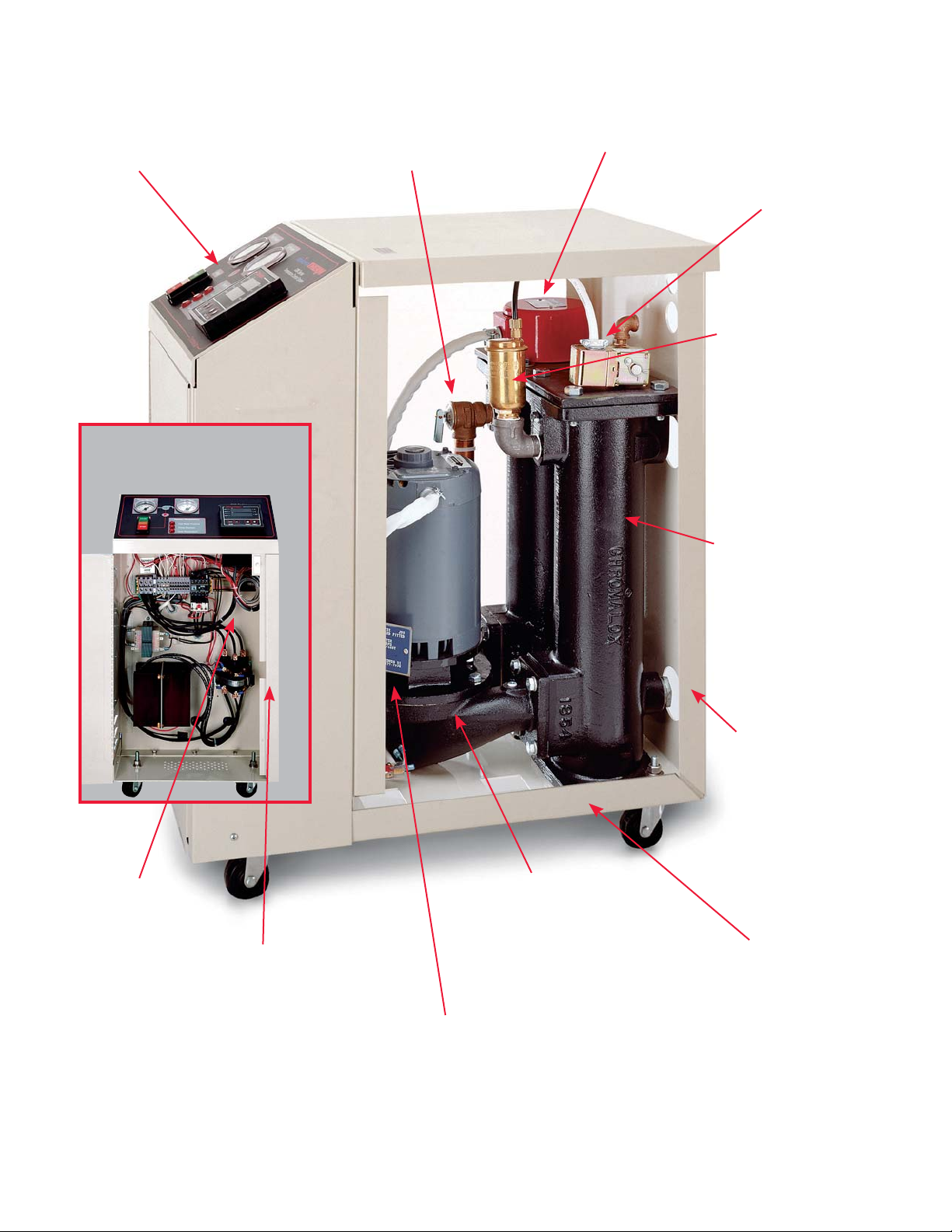
Figure 1.1 System Photo (Side View)
Operating temperatures of 50° to 250°F
for a wide variety of applications.
Internal system configuration separates
electronics from mechanical systems,
reducing heat buildup and providing
a safer operating system.
ASME pressure relief valve opens if system pressure exceeds 125 psi, ensuring
safe operation.
High watt density, INCOLOY
Chromalox® heating elements.
Integral solenoid valve for precise temperature control and
optimum flow.
®
sheath
Automatic air purge cycle
removes accumulated air
from water lines.
Standard 3.8 sq. ft. heat exchanger (closed loop cooling)
Pump overload circuit protects
systems from damage in event
of excessive current draw in
the motor.
Long-life mercury contactor switches
heater power for millions of cycles and
quiet, trouble-free operation.
Thermal Devices, Inc. Mount Air
Cabinet design allows
access to all components without removing
a single fastener.
Custom cast pump for optimum flow,
minimum leakage and long life.
Compact, rugged cabinet fits into tight
spaces. Rolling casters allow easy
transfer between locations.
Low pressure switch disables system when
supply pressure is low, preventing cavitation in
pump and protecting the system.
2
, Maryland USA www.thermaldevices.com
Page 5
Thermal Devices, Inc. Mount Airy, Maryland USA www.thermaldevices.com
y
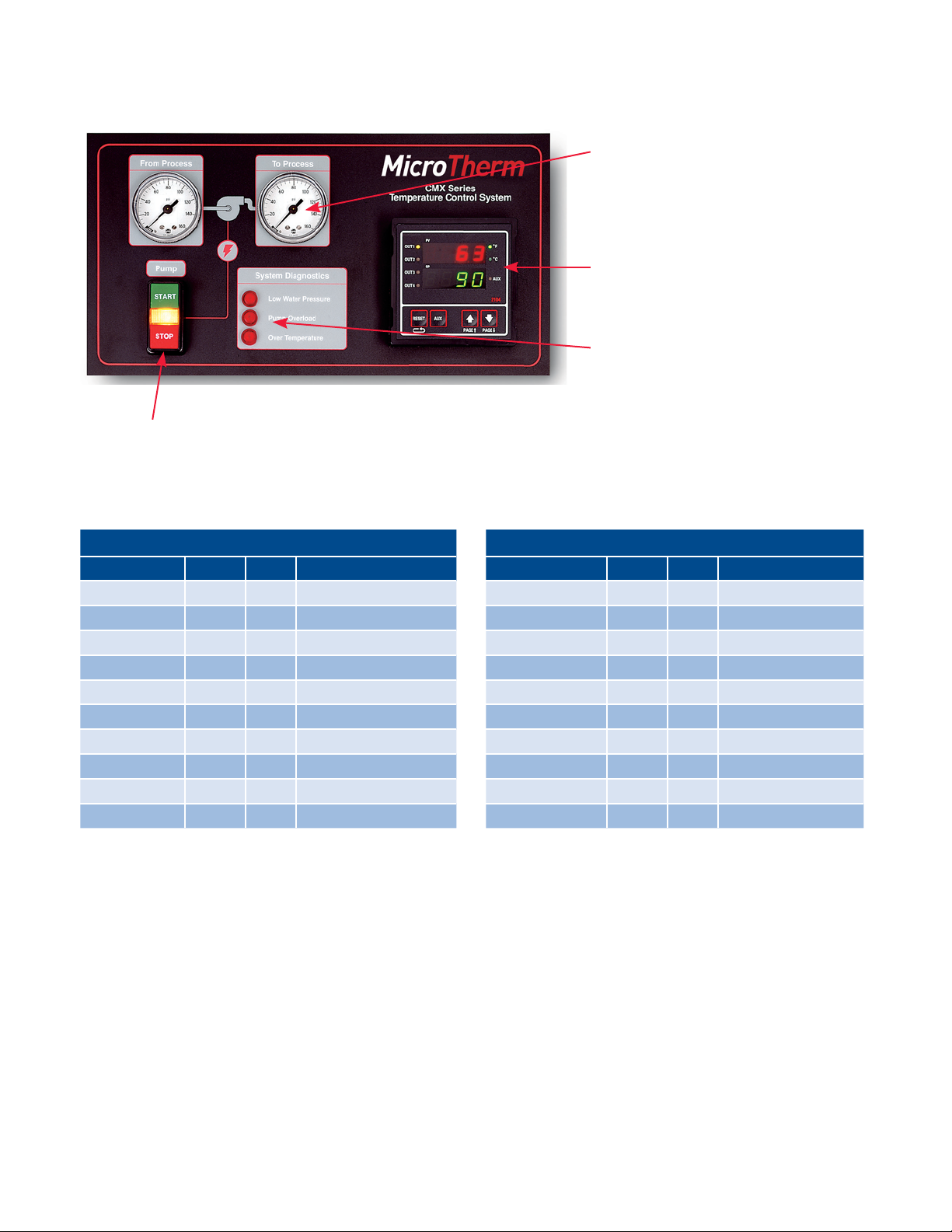
Figure 1.2 Control Panel
Pump START/STOP Pushbuttons
Du al p re ssu re g au ge s s implif y mo ni to rin g o f b ot h
to process and from process pressures.
Chromalox’s Temperature and Process Controller
features separate PID algorithms for heat and
cool control modes, dual display of setpoint and
process temperatures, and simple configuration
parameters with alphanumeric cues. Optional
digital communications expand microTHERM’s
application flexibility. (Controller model supplied
may vary from picture)
Diagnostic Indicators allow you to constantly
monitor microTHERM’s performance, giving you
early detection of potential problems before they
occur and simplifying maintenance.
Ordering Information
Open Loop Cooling
Model kW Volts Total Amperage
CMX-250-4 4.5 240 13.6
CMX-250-4 4.5 480 6.8
CMX-250-9 9 240 24.5
CMX-250-9 9 480 12.2
CMX-250-12 12 240 31.7
CMX-250-12 12 480 15.8
CMX-250-18 18 240 46.1
CMX-250-18 18 480 23.1
CMX-250-24 24 240 60.5
CMX-250-24 24 480 30.3
Closed Loop Cooling
Model kW Volts Total Amperage
CMX-250-4C 4.5 240 13.6
CMX-250-4C 4.5 480 6.8
CMX-250-9C 9 240 24.5
CMX-250-9C 9 480 12.2
CMX-250-12C 12 240 31.7
CMX-250-12C 12 480 15.8
CMX-250-18C 18 240 46.1
CMX-250-18C 18 480 23.1
CMX-250-24C 24 240 60.5
CMX-250-24C 24 480 30.3
Thermal Devices, Inc. Mount Air
3
, Maryland USA www.thermaldevices.com
Page 6
Thermal Devices, Inc. Mount Airy, Maryland USA www.thermaldevices.com
y
Section 2 – Installation
Before Open-Loop Hydraulic Installation:
Before proceeding with the installation of the openloop system, please take note of the following important information:
1. Reduced diameter fittings may be used if they do
not reduce flow rate and increase pressure drop
significantly. Galvanized steel unions are recommended at all connections.
2. If water pressure falls below 20 psi, a pressure
switch will interrupt pump motor and heater operation. Use an external water pressure regulator
and back pressure relief valve or regulator, set at
maximum 125 psi (150 psi with 7.5 hp motor) connected in the external fill line, to reduce excessive
water pressure. Not provided on CMX-180 models.
HAZARD OF EXPLOSION, FIRE AND SCALDING
BURNS.
The water feed line on both open and closed
loop systems must not have any obstructions
which could prevent expanding water from
backing up into the feed line.
Do not use oils or other synthetic heat transfer fluids. This system is for use with water or
ethylene glycol and water mixture for freeze
protection only as the heat transfer fluid.
When installing system, allow sufficient room
to remove the heater element and other serviceable items when necessary. 18 inches
clearance on sides of unit recommended.
If the water source is a potable water source,
a back flow preventer and back pressure relief
valve/regulator should be installed and may be
required by local code. Do not install a check
valve only on the fill line. The inability of the
system to flow back into the fill line can lead
to excessive pressure. Back pressure relief is
required.
To avoid excessive pressures, do not connect
any valves or obstructions which could prevent
free discharge from relief valve in a safe manner. Route line so water drains completely. Do
not allow drain to freeze or corrode shut.
Hydraulic Installation, Open Loop:
1. Locate the unit as close as possible to the controlled process in order to minimize pressure
drops. Make sure the unit is sitting on a solid, level
foundation.
2. Using 1 1/4” NPT or larger schedule 40 pipe (flexible hose suitable for 150 psi and 250°F minimum
service conditions can be used), connect the 1
1/4” NPT “FROM PROCESS” and “TO PROCESS”
ports to the mold, mold manifold, or other process.
3. Pipe the entire system to minimize air pockets.
Provide air bleed valves at high points and drains
at low points.
4. Connect the plant water supply (30 psi to 80 psi)
to the unit’s 1/2” NPT “WATER SUPPLY/COOLING
INLET” port with suitable pipe or hose.
HAZARD OF EXPLOSION, FIRE AND SCALDING
BURNS.
Connect the 1/4” NPT port identified as “DRAIN
COOLING OUTLET” to an open or plant drain
that contains no valves or obstructions that
could impede discharge. Review the condition
of potential hot water or steam going down a
plant drain. Verify that local codes and materials are acceptable for this service.
Locate floor drain under unit. The air bleed and
relief valve may discharge hot water or steam
from the bottom of the unit. Do not locate materials that could be damaged by hot water or
steam adjacent to the unit.
Temperature Controller
Cooling
Valve
Drain/Cooling
(1/4 NPT)
From Process
(1-1/4 NPT)
Outlet
Auto
Air Bleed
Pressure
Relief
Valve
Pump and
Motor
Heater
Therocouple
Probe
To Process
(1-1/4 NPT)
Thermal Devices, Inc. Mount Air
Water Supply/
Cooling Inlet
(1/2 NPT)
Figure 2.1 Open-Loop System Piping
4
, Maryland USA www.thermaldevices.com
Page 7
Thermal Devices, Inc. Mount Airy, Maryland USA www.thermaldevices.com
y
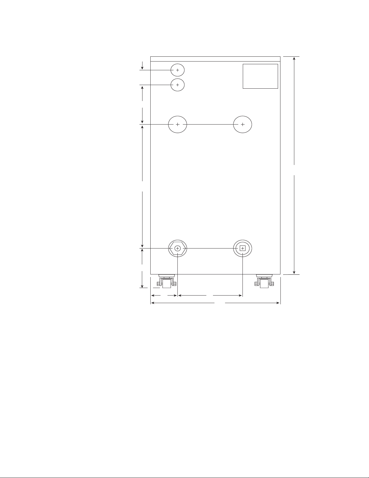
Figure 2.1 Open-Loop Cooling Piping Connections
1-7/8”
6"
12-5/16”
FROM PROCESS
WATER SUPPLY/
COOLING INLET
DRAIN/
COOLING OUTLET
TO
PROCESS
Chromalox
®
28-1/2”
6"
4"
7"
15"
Rear View
Note: Dimensions are nominal ± 3/8”
Thermal Devices, Inc. Mount Air
5
, Maryland USA www.thermaldevices.com
Page 8

Thermal Devices, Inc. Mount Airy, Maryland USA www.thermaldevices.com
y
Before Closed-Loop Hydraulic Installation
Before proceeding with the installation of the Closedloop system, please take note of the following information:
1. Reduced diameter fittings may be used if they do
not reduce flow rate and increase pressure drop
significantly. Galvanized steel unions are recommended at all connections.
2. If water pressure falls below 20 psi, a pressure
switch will interrupt pump motor and heater operation. Use an external water pressure regulator
and back pressure relief valve or regulator set at
maximum 125 psi (150 psi with 7.5 hp motor) connected in the external fill line, to reduce excessive
water pressure. Not provided with CMX-180 models.
HAZARD OF EXPLOSION, FIRE AND SCALDING
BURNS. To avoid excessive pressures, do not
connect any valves or obstructions which could
prevent free discharge from relief valve in a
safe manner. Route line so water drains completely. Do not allow drain to freeze or corrode
shut.
Do not install a check valve on the fill line. The
inability of the system to flow back into the
fill line can lead to excessive pressure. If back
flow preventer or check valve is required, install back pressure regulator rated for 250°F
water with a pressure setting of 30 to 80 psi.
Back pressure regulator setting must be approximately 10 psi above water supply pressure to minimize water flow directly from supply to drain.
4. Connect the cooling water supply (30 psi to 80 psi)
to the unit’s 1/2” NPT “WATER SUPPLY/COOLING
INLET” port with suitable pipe or hose.
5. Connect the 1/4” NPT port identified as “COOLING OUTLET” to a cooling water return line or plant
drain that contains no valves or obstructions that
could impede discharge. Review the condition of
potential hot water going down a plant drain. Verify
that local codes and materials are acceptable for
this service. Temperature of discharge water could
reach 250°F and create steam at atmospheric
pressure.
Temperature Controller
Solenoid
Cooling Outlet
(1/2 NPT)
Water Supply/
Cooling Inlet
(1/2 NPT)
From Process
(1-1/4 NPT)
Valve
Auto
Air Bleed
Pressure
Relief
Valve
Pump and
Motor
Heater
Therocouple
Probe
To Process
(1-1/4 NPT)
Figure 2.3 Closed-Loop System Piping
Hydraulic Installation Closed-Loop
1. Locate the unit as close as possible to the controlled process in order to minimize pressure
drops. Make sure the unit is sitting on a solid, level
foundation.
2. Using 1 1/4” NPT or larger schedule 40 pipe (flexible hose suitable for 150 psi and 250°F minimum
service conditions can be used), connect the 1
1/4” NPT “FROM PROCESS” and “TO PROCESS”
ports to the mold, mold manifold, or other process.
3. Pipe the entire system to minimize air pockets.
Provide air bleed valves at high points and drains
at low points.
Thermal Devices, Inc. Mount Air
, Maryland USA www.thermaldevices.com
6
Page 9

Thermal Devices, Inc. Mount Airy, Maryland USA www.thermaldevices.com
y
Figure 2.1 Open-Loop Cooling Piping Connections
S” and “TO PR
1-7/8”
6"
12-5/16”
COOLING OUTLET
WATER SUPPLY/
COOLING INLET
FROM PROCESS
PROCESS
TO
Chromalox
®
28-1/2”
6"
Thermal Devices, Inc. Mount Air
4"
7"
15"
Rear View
Note: Dimensions are nominal ± 3/8”
7
, Maryland USA www.thermaldevices.com
Page 10

Thermal Devices, Inc. Mount Airy, Maryland USA www.thermaldevices.com
y
Electrical Installation
HAZARD OF ELECTRIC SHOCK. The heat transfer system must be grounded using grounding
means provided in control box and employing
wiring by a qualified electrician in accordance
with National Electric Code. Failure to comply
can result in electrical shock or electrocution.
HAZARD OF ELECTRIC SHOCK. Disconnect all
power before servicing the heat transfer system. Failure to comply can result in electrical
shock or electrocution.
Fusing or other over-current protection must be supplied to the system by the user.
The unit is completely wired when shipped. The only
wiring necessary is to the blue colored terminals L1,
L2, L3, and the green and yellow colored ground. To
make these connections:
4. Pump Rotation Check: With power off, check the
wiring connections by tugging on the lines. Tighten
all terminals in the control area. These can loosen
due to vibration in shipping.
5. Close the front electrical enclosure door. Pull the
top cover off of the heat transfer system and locate
the top of the pump motor.
6. With the supply water connected, and adequate
pressure present, Press the
tons in quick succession. Watch the rotation on the
pump motor to insure it matches the label on its
top.
7. If rotation is incorrect, disconnect power to the
system and swap any two of the supply lines. Repeat rotation check.
Close the front electrical enclosure door and
retighten the locking screw. This must be done
to limit access to high voltage components.
Failure to comply could lead to electric shock
or electrocution.
START
and
STOP
but-
Figure 2.5 Power Connection Terminals
1. Loosen the screw on the front electrical enclosure
door to unlock the latch.
2. Open the front electrical enclosure door. Using
90°C wire sized per National and local codes, run
each leg of the three phase supply power and
ground to the appropriate terminals as shown in
Figure 2.5.
3. A separate fused disconnect is required. Locate
this fused disconnect near the equipment. Codes
may require the location of disconnect in sight of
operation standing next to the equipment. Consult
applicable codes for details.
Control Voltage Fusing
Terminal block #1 (see Figure 2.5) contains a 120V fuse
for the control circuitry. This fuse protects the control
transformer and circuitry.
1. Should the fuse blow, an indicator will light on the
terminal block.
2. Disconnect power from the system.
3. Determine the cause of the blown fuse.
4. Replace with an equivalent fuse.
5. Reconnect power.
Thermal Devices, Inc. Mount Air
8
, Maryland USA www.thermaldevices.com
Page 11

Thermal Devices, Inc. Mount Airy, Maryland USA www.thermaldevices.com
y
Section 3 – Temperature Control Operations
Figure 3.1 Control Panel Layout
START/STOP Pushbuttons
START
Press
pump.
Indicator will illuminate while
pump is running. Press
STOP
to start the
to stop the pump.
Status and Diagnostic Indicators
System shuts down if any red diagnostic indicator is
illuminated.
Low Water Pressure:
• System water pressure is below 20 psi.
(Disabled on CMX-180 models)
Pump Overload:
• Pump has drawn too much current.
Over Temperature:
• System temperature has exceeded 260°F.
Most CMX units shipped from 1995 through 2018 will
have been equipped with a Chromalox model 2104
temperature controller. For these units, please reference the 2104 Quick Info Manual or Instruction Manual
0037-75276 for complete technical details.
For specific controller Set-up Parameters, please refer
Chromalox Manual PQ445-5
Most CMX units shipped from 2019 and onward will
have been equipped with a Chromalox model 4081
(standard controller) or 4082 (advanced controller). For
these units, please reference the 4081 & 4082 Quick
Start Manual, Document PK531 (0037-75563) or Instruction manual PK532-1 (0037-75562) for complete
technical details.
Temperature Control
Actual controller supplied may vary from picture.
Below is a list of the most common controller setups,
with additional details available in Appendix C
CMX-250, Contactor – Dwg. 223-123625-053
CMX-275, Contactor – Dwg. 223-123625-052
CMX-250, SCR – Dwg. 223-123625-055
CMX-275, SCR – Dwg. 223-123625-058
CMX-250, Heat-Only – Dwg. 223-123625-057
CMX-275, Heat-Only – Dwg. 223-123625-059
Thermal Devices, Inc. Mount Air
9
, Maryland USA www.thermaldevices.com
Page 12

Thermal Devices, Inc. Mount Airy, Maryland USA www.thermaldevices.com
y
Section 4 – Operation
On both open Closed-loop systems, turn on water and insure the water supply lines are free
of obstructions BEFORE energizing the heater.
Such obstructions could prevent the thermal
expansion of water from backing up into this
line, thereby increasing system pressure until
the relief valve opens.
Note: This system is equipped with an ASME
safety pressure relief valve (factory preset at
125 psi or 150 psi with 7.5 hp motor).
1. Apply power to the system via the remote discon-
nect. The temperature controller and “LOW WATER
PRESSURE” diagnostics light should illuminate.
2. Open supply-water line and process valving to al-
low system to fill. Auto air bleed will remove air from
the system. Any remote air bleed valves should be
opened to remove air from process and associated
piping.
3. “LOW WATER PRESSURE” diagnostic light should
go out when the system is filled and has reached
20 psi. The system will not start when light is illuminated.
4. Adjust the temperature setpoint to the desired lev-
el.
5. Assure that Pump Rotation Check was performed
per instructions on page 12.
6. Start the pump by pressing on the front panel. The
pump indicator light will illuminate.
7. Once temperature has stabilized at the setpoint
level, review controllability of the system. If the
temperature is fluctuating at an unacceptable level,
consult the temperature control instruction manual
for details on tuning the controller.
8. If the system temperature is below the current set-
point, heat will be applied by the controller to the
heater elements. If the temperature is above the
setpoint, the cooling solenoid will open (open and
closed loop) to reduce the system temperature.
down to prevent release of hot fluid.
Note: This is a PID type controller and cycling of the
heat and cool can be expected below and above setpoint.
9. For system shutdown, lower the setpoint to 90°F or
lower, Allow the system to cool to this temperature
level.
10. Press to de-energize the pump and disable the
system.
11. Disconnect power to the unit.
Do not leave system unattended in a HOT electrical condition; and do not leave system unattended in HOT environmental conditions.
Operating systems at temperatures above
140°F will create surface temperatures on
pipes that can cause burns. Precautions should
be taken to prevent operator contact with hot
pipes. Also, bleed valves should be locked
Thermal Devices, Inc. Mount Air
, Maryland USA www.thermaldevices.com
10
Page 13

Thermal Devices, Inc. Mount Airy, Maryland USA www.thermaldevices.com
y
Section 5 – Diagnostics
Figure 5.1 Diagnostic Indicators
HAZARD OF ELECTRIC SHOCK. Disconnect
system power, if the Pump Overload Indicator
is illuminated. Hazard of electric shock or electrocution. Disconnect all power and piping to
the system.
After the system power is disconnected, solve the
electrical current problem. To put the pump back online, open the front electrical enclosure and press the
pump reset switch (See Figure 5.2, Overload Switch).
Diagnostic Functions
All diagnostic functions will shut down the system and
require the operator to remedy the problem before it
can be restarted.
Low Water Pressure Indicators
The pump, heater, and cooling will not operate while
the pressure is low. The Low Water Pressure Indicator will illuminate when the system pressure is below
20 psi. This warning system is designed to reduce the
possibility of pump cavitation and boiling on the heater
element at higher operating temperatures. Disabled on
CMX-180 models.
Pump Overload Indicator
The Pump Overload Indicator will illuminate when the
pump draws too much current. Low line voltage, single
phase power input, and a seized pump motor are all
possible causes for pump overload.
Figure 5.2 Pump Reset Switch
Close the front electrical enclosure door and
retighten the locking screw. This must be done
to limit access to high voltage components.
Failure to comply could lead to electric shock
or electrocution.
Over Temperature Indicator
If the system temperature exceeds 260°F (127°C), the
Over Temperature Indicator will illuminate. When the
system temperature drops below 260°F*, press RE-
SET on the controller face. The controller will not reset
until the temperature is below 260°F*.
*
190°F on CMX-180 model(s)
Thermal Devices, Inc. Mount Air
11
, Maryland USA www.thermaldevices.com
Page 14

Thermal Devices, Inc. Mount Airy, Maryland USA www.thermaldevices.com
y
Section 6 – Maintenance
ELECTRIC SHOCK AND BURN HAZARD. Disconnect all power before servicing or performing
maintenance to the system. Do not attempt to
service system while it is operating or while
hot. Failure to comply can result in:
a. Electric shock.
b. Burns from hot heating elements, piping,
and hot oil or water.
c. Injury from operating or rotating pump and
motor.
Maintenance is to be performed by qualified
personnel only. Thoroughly read and understand these instructions. Consult the factory if
you have any questions.
Shut Down
To take the unit out of service, the following steps must
be done in sequence:
1. Set the temperature controller setpoint to 90°F or
lower. Allow to cool.
2. Turn off power to the unit. The controller will turn
off.
3. Turn off the water supply to the unit.
4. Disconnect electrical supply to the unit.
5. Carefully bleed pressure from the system by loosening a pipe fitting.
Draining
Drain the unit before taking it out of service for a period of time, or if it is exposed to freezing temperatures
while out of service.
1. To drain the unit completely, move it to an inclined
position with the front of the system raised.
2. Remove the lower plugs on cast chambers (see
Figure 6.1, Chamber Photo).
Remove these
plugs
Figure 6.1 Chamber Photo
System may be pressurized. Use extreme care
while removing piping. Disconnect water supply, drain and process connections.
6. Drain all water from the system.
Thermal Devices, Inc. Mount Air
, Maryland USA www.thermaldevices.com
12
Page 15

Thermal Devices, Inc. Mount Airy, Maryland USA www.thermaldevices.com
y
Heater Removal/Replacement
HAZARD OF ELECTRIC SHOCK. Disconnect all
power and piping to system.
1. Disconnect all power to the system.
2. Bleed pressure and drain all water from the system.
3. Remove top panel.
4. Remove red top cover on the heater (see Figure
6.2, Heater/Chamber Photo).
5. Note location of wires on the heater, then remove
wires (L1, L2, L3).
6. Loosen compression fitting on the heater power
supply cable.
Figure 6.2 Heater/Chamber Photo
7. Remove cable from the heater.
8. Unbolt the heater (4 bolts) and remove.
9. Remove Bussing from old heater and re-install on
replacement heater, using the same orientation.
10. Replace heater and reverse procedure.
Close the front electrical enclosure door and
retighten the locking screw. This must be done
to limit access to high voltage components.
Failure to comply could lead to electric shock
or electrocution.
Remove Top Panel
Remove Top Cover
on Heater
Thermal Devices, Inc. Mount Air
13
, Maryland USA www.thermaldevices.com
Page 16

Thermal Devices, Inc. Mount Airy, Maryland USA www.thermaldevices.com
y
Pump Removal/Replacement
HAZARD OF ELECTRIC SHOCK. Disconnect all
power and piping to system.
1. Disconnect all power to the system.
2. Bleed pressure and drain all water from the system.
3. Remove top and side panels.
4. Remove pump motor wiring cover panel (2 screws).
5. Note location of pump motor wires and remove.
6. Loosen and remove vent line (see Figure 6.3, Motor
Vent Line).
7. Remove bolts holding pump motor to the casting
(4 bolts), and lift motor out of casting.
8. Remove impeller and install new mechanical seal
and impeller on the new motor.
9. Place new motor in system and bolt down.
10. Replace vent line and tighten.
11. Reconnect wires and replace wiring cover and side
panels.
12. Reconnect the system.
13. Perform Pump Rotation Check (see Section 2,
page 12).
14. Replace top panel.
Heat Exchanger Removal/Replacement
(Closed loop system)
1. Disconnect all power to the system.
2. Bleed pressure and drain all water from the system.
3. Remove top panel.
4. Remove cover on the cooling solenoid (see Figure
6.4, Heat Exchanger).
5. Disconnect “COOLING INLET” and “COOLING
OUTLET” piping.
6. Disconnect copper tubing connected to the heat
exchanger.
7. Unbolt the heat exchanger and remove (4 bolts).
8. Place new heat exchanger in system and bolt
down.
9. Reconnect “COOLING INLET” and “COOLING
OUTLET” piping.
10. Reconnect wires to the cooling solenoid.
11. Reconnect copper tubing.
12. Replace cover on cooling solenoid and top panel.
13. Replace system water and reconnect the system.
Close the front electrical enclosure door and
retighten the locking screw. This must be done
to limit access to high voltage components.
Failure to comply could lead to electric shock
or electrocution.
Close the front electrical enclosure door and
retighten the locking screw. This must be done
to limit access to high voltage components.
Failure to comply could lead to electric shock
or electrocution.
Heater Element
Housing
Pump/Motor Vent Line
Figure 6.3 Motor Vent Line
Motor
Pump Housing
Top Panel
Figure 6.4 Heat Exchanger
Cooling Solenoid
Heat Exchanger
Thermal Devices, Inc. Mount Air
14
, Maryland USA www.thermaldevices.com
Page 17

Thermal Devices, Inc. Mount Airy, Maryland USA www.thermaldevices.com
y
Replacement Heating Elements and Contactors
MicroTHERM Model Replacement Parts
Open Loop Closed Loop Voltage Heating Element Heater Contactor
CMX-4 CMX-4C 240 155-554807-523 072-057576-050
CMX-4 CMX-4C 480 155-554807-523 072-057576-050
CMX-9 CMX-9C 240 155-554807-512 072-057576-050
CMX-9 CMX-9C 480 155-554807-512 072-057576-050
CMX-12 CMX-12C 240 155-554807-524 072-057576-050
CMX-12 CMX-12C 480 155-554807-524 072-057576-050
CMX-18 CMX-18C 240 155-554807-519 072-057576-051
CMX-18 CMX-18C 480 155-554807-519 072-057576-050
CMX-24 CMX-24C 240 155-554807-515 072-057576-051
CMX-24 CMX-24C 480 155-554807-515 072-057576-050
Replacement Parts Common to All Models
Identification # Part Name Part Number
1 3/4 HP Motor 240V/480V 193-121843-227
2 Solenoid Valve 344-121780-012
3 Pressure Relief Valve 344-048419-004
4 Automatic Air vent 344-053181-001
5 Pressure Gauge 130-118661-021
6 Pressure Switch 292-121927-028
7 Pump Mechanical Seal 251-121946-019
8 Heat Exchanger Bundle (Closed Loop) 353-123367-002
9 Heater/Cooling Gasket (2 total) 132-146012-020
10 Thermocouple 309-121759-063
11 Switch, Start/Stop
Switch Indicator Bulb
12 Diagnostic Indicator Light (3 total) 213-122066-041
13 Motor Contactor 240/480V 072-123534-064
14 Auxillary Motor Contact Block 071-122886-055
15 Motor Thermal Overload 240V
Motor Thermal Overload 480V
16 Transformer 240/480V 315-303786-001
17 Caster (4 total) 375-123425-003
18 Control Voltage Fuse 128-123445-005
19 Heater Contactor See table above
292-122882-043
213-122066-034
359-122078-096
359-122078-095
These parts may vary for non-catalog items.
Please consult your local Chromalox representative. (800-443-2640 or www.chromalox.com)
15
Thermal Devices, Inc. Mount Air
, Maryland USA www.thermaldevices.com
Page 18

Thermal Devices, Inc. Mount Airy, Maryland USA www.thermaldevices.com
y
Figure 6.6 Replacement Parts Identification
From Process
5
12
Pump
START
ST
OP
CONNECT
_____VOLT
SUPPLY
HERE
System Diagnostics
Low Water Pressure
Pump Overload
Over Temperature
13
19
FUSE
1F
To Process
5
Temperature Control System
Chromalox
HEAT
COOL
OUT3
OUT4
RESET AUX
15
AUX. CONTACT BLOCK
1M
CMX Series
®
PV
SP
Chromalox
PAGE
F
C
AUX
PAGE
®
17
TRANSFORMER
MOTOR CONTACTOR
MOTOR THERMAL
OVERLOAD
16
HEATER
CONTACTOR
20
14
1C
Thermal Devices, Inc. Mount Air
16
, Maryland USA www.thermaldevices.com
Page 19

Thermal Devices, Inc. Mount Airy, Maryland USA www.thermaldevices.com
y
Section 7 – Troubleshooting
Troubleshooting Guide - For qualified personnel only. See warnings in earlier sections.
Symptom Probable Cause Correction
Unit will not start, control
display does not light.
Control display lights, unit
will not start
Unit stops while running
Low Water Pressure
Indicator Illuminated
Pump Overload Indicator
illuminated
Over Temperature
Indicator illuminated
Unit runs but fails to
pump.
1. Unit not wired correctly. 1. Check wiring.
2. Disconnect switch OFF. 2. Turn disconnect ON.
3. Blown fuse. 3. Check customer disconnect fuses and
120V fuse on terminal block (blown fuse indicator will light if fuse is blown).
4. Wrong voltage. 4.
1. Cooling water off, or below 20
psi. (CMX-250 models only)
2. Pump Motor Overload 2. Determine problem and press pump reset.
3. System above temperature
limit of 260°F. (190˚F on CMX180 Models)
1. Cooling water drops below 20
psi
2. Pump motor overload 2. Determine problem and press pump reset.
3. System exceeds temperature
limit of 260˚F (190˚F on CMX-180
Models)
1. Cooling water drops below 20
psi (CMX-180 models)
1. Pump motor overload 1. Determine the problem and press pump
1. System above temperature
limit of 600°F.
1. Incoming phase reversed on
pump motor.
Check supply voltage & unit’s rated voltage.
1. Open cooling water valve, check to assure
pressure is above 30psi
3. Allow unit to cool below 260°F and press
RESET.
1. Check cooling water valve, check to assure above 30 psi
3. Allow unit to cool below 260°F and press
RESET.
1. Check that pressure is above 30 psi
reset button
1. Allow unit to cool below 550°F and press
reset on over temperature controller inside
the panel. See Section 5.
1. Swap any two legs on the incoming power.
Unit will not heat to
setpoint.
Unit will not cool to
setpoint.
If you continue to have problems with the system after review of the above issues, please contact Chromalox
Product Service at 800-443-2640.
Thermal Devices, Inc. Mount Air
1. Cooling valve stuck open. 1. Check for cooling water flow during heat
cycle.
2. Heater element failure. 2. Check current at heater contactor during
heating.
3. Heater output insufficient. 3. Excessive losses in process or incorrectly
sized unit for application.
4. Controller needs to be tuned. 4. Check factory MENU settings, Section 3 of
this manual. Refer to 2104 Controller Technical Manual, page 35, for further information.
1. Inadequate cooling water flow. 1. Open cooling water supply line more and
assure adequate pressure.
2. Cooling outlet obstructed. 2. Check cooling outlet for obstructions
3. Heater contactor fused
closed.
4. Controller needs to be tuned. 4. Check factory MENU settings, Section 3 of
17
3. Check voltage across contactor during
cooling cycle.
this manual. Refer to 2104 Controller Technical manual, page 35, for further information.
, Maryland USA www.thermaldevices.com
Page 20

Thermal Devices, Inc. Mount Airy, Maryland USA www.thermaldevices.com
y
Section 8 – Specifications
Standard 3/4 HP Pump
Heating
Pump
Size (HP)
Nominal
Flow (gpm)
Capacity
(kW)
Standard
Voltages
3/4 30 4.5 240 or 480 1-1/4 NPT 1/4 NPT 29 height
3/4 30 9 240 or 480 1-1/4 NPT 1/4 NPT 29 height
3/4 30 12 240 or 480 1-1/4 NPT 1/4 NPT 25 depth
3/4 30 18 240 or 480 1-1/4 NPT 1/4 NPT 15 width
3/4 30 24 240 or 480 1-1/4 NPT 1/4 NPT 15 width
Optional Pump Sizes
Optional Pump Sizes
(HP)
Nominal Flow
(gpm)
1.5 40
350
560
7.5 80
Five Pump sizes are available for the flow rate
appropriate to your process application.
Ft.
PSI
180
78
160
69
61
140
52
120
43
100
80
35
26
60
17
40
9
20
0 20 40 60 80 100 120
3/4 HP
1.5 HP
U.S. Gallons Per Minute
3 HP
7.5 HP
5 HP
Process
Connection
dia. (Inches)
Drain/Supply
dia. (Inches)
Approximate
Optional Options
• Alternate Voltages: 208, 380, 575 VAC, 3 phase
• Expanded Open Loop Cooling: increased cooling
water flow
• Expanded Closed Loop Cooling: 6.3 sq. ft. heat
exchanger
• Solid State Power Control: SCR heater switching
• Surge Reduction valve: reduces water pressure
spikes
• Door Interlock: prevents operation with service
door open
• Digital Communications: for interface with ChromaSoft or remote PC/PLC systems
• IEC Style Contactor: for dry contact power switching
• Isolation Valve Kit: 1” ball valve for system isolation
Dimensions
(Inches)
Pump Capacity
Figure 8.1 - Pump Capacity
Thermal Devices, Inc. Mount Air
18
, Maryland USA www.thermaldevices.com
Page 21

Thermal Devices, Inc. Mount Airy, Maryland USA www.thermaldevices.com
y
Appendix A
microTHERM CMX Closed Loop to Open Loop Cooling Conversion
Note: All warnings and cautions denoted
throughout this user’s manual also apply to the
modifications listed below. General instructions and specifications referring to the open
and closed loop systems apply to the fieldmodified units below.
New Material Required
1. 1/4” NPT Pipe Plug 1 piece 218-075439-036
2. 1/4” NPT x 1-1/2” Nipple 1 piece 198-122817-013
3. 1/4” NPT Elbow 1 piece 107-122815-001
4. 1/4” NPT Close Nipple 1 piece 198-122817-002
5. 1x1/2” NPT Reducer 1 piece 032-120942-019
6. Open loop cooling flange 1 piece 121-510702-017
Replacement Steps
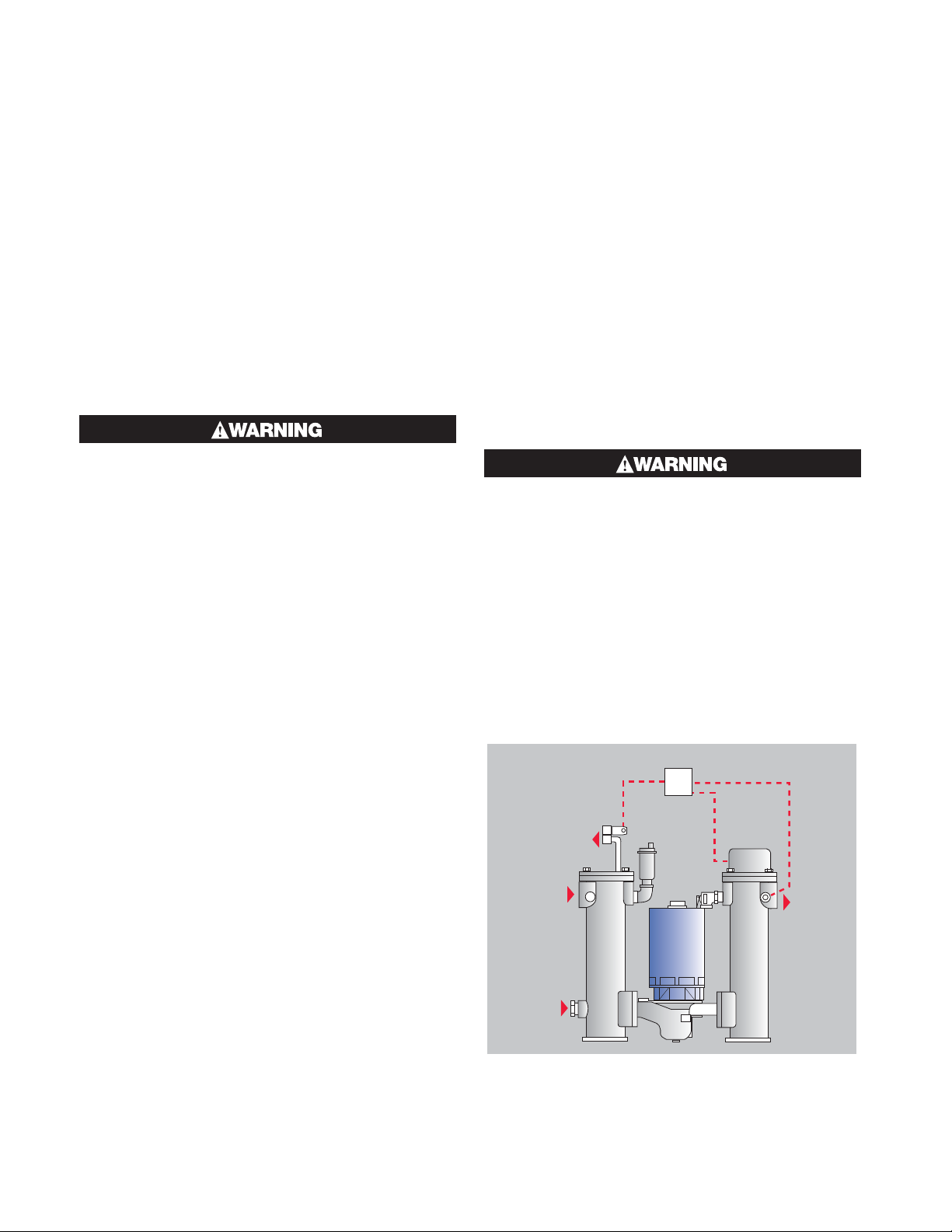
Figures 1 and 2 show the layout of the cooling configuration for both closed and open loop cooling. These parts
are located on the top of the cooling chamber. Use pipe tape or other sealing compound when attaching threaded
connections.
This sheet details the steps taken and material required
to convert a Chromalox CMX microTHERM hot water
system from closed loop cooling to open loop cooling. The basic operation involves removing the heat exchanger bundle and replacing it with a flat plate. Please
contact the Chromalox Customer Service department
for more information and to order the necessary materials.
or
Figure A1 - Closed Loop Cooling
Note: Refer to Figures 3 and 4 for location of compo-
nents.
1. Remove (47) 3/8” copper tube and compression
fittings from heat exchanger and tee above pump
inlet.
2. Place 1/4” pipe plug into tee above pump inlet
where copper tube was connected.
3. Pop magnetic coil from top of (43) solenoid valve
and leave wired to system.
4. Remove (43) solenoid valve from top of heat exchanger and keep for reinstallation.
5. Remove four (9) bolts and lift (42) heat exchanger
from cooling chamber.
Thermal Devices, Inc. Mount Air
, Maryland USA www.thermaldevices.com
Figure A2 - Open Loop Cooling
6. Reuse rubber gasket and (9) bolts to attach new
(42) cooling flange to cooling chamber.
7. Attach new (40) 1-1/2” nipple to flange.
8. Attach (43) solenoid and magnetic coil to nipple.
9. Attach new (15) close nipple and new (39) elbow to
solenoid.
10. Replace 1” pipe plug from lower cooling chamber
port with 1 x 1/2” reducer.
11. Lower cooling chamber port becomes the new
cooling inlet.
19
Page 22

Thermal Devices, Inc. Mount Airy, Maryland USA www.thermaldevices.com
y
Appendix B
microTHERM CMX Open Loop to Closed Loop Cooling Conversion
Note: All warnings and cautions denoted
throughout this user’s manual also apply to the
modifications listed below. General instructions and specifications referring to the open
and closed loop systems apply to the fieldmodified units below.
New Material Required
1. 1/4” NPT Tee 1 piece 299-122818-001
2. 1/2” NPT Tee 1 piece 299-122818-003
3. 1/4” NPT x 7/8” Nipple 1 piece 198-122817-002
4. 1/2” NPT x 3” Nipple 1 piece 198-122817-090
5. 1/2” NPT Street Elbow 1 piece 107-114567-005
6. Bush Reducer 1/2” x 1/4”NPT 2 pieces 032-121003-005
7. Compression Fitting, 1/4” NPT x 3/8” tube 2 pieces 119-114570-001
8. Tubing 3/8” copper 2 Feet 318-511965-001
9. Gasket 1 piece 132-146012-020
10. Heat Exchanger Tube Bundle 1 piece 353-123367-002
11. 1” NPT Pipe Plug 1 piece 218-075439-066
12. Labels 1 piece 170-122103-040
This sheet details the steps taken and material required
to convert a Chromalox CMX microTHERM hot water
system from open loop cooling to closed loop cooling.
The basic operation involves removing the flat plate
and replacing it with a heat exchanger bundle. Please
contact the Chromalox Customer Service department
(1-800-368-2493) for more information and to order the
necessary materials.
Replacement Steps
Figures 1, 2, 3 and 4 show the layout of the cooling configuration for both closed and open loop cooling. These
parts are located on the top of the cooling chamber. Use pipe tape or other sealing compound when attaching
threaded connections.
or
Figure B1 - Closed Loop Cooling
Note: Refer to Figures 3 and 4 for location of components.
Figure B2 - Open Loop Cooling
Thermal Devices, Inc. Mount Air
20
, Maryland USA www.thermaldevices.com
Page 23

Thermal Devices, Inc. Mount Airy, Maryland USA www.thermaldevices.com
y
DRAIN /
COOLING
OUTLET
FROM
PROCESS
WATER SUPPLY
COOLING
INLET
TO
PROCESS
Fig. 2
OPEN LOOP
COOLING
OUTLET
WATER
SUPPLY
COOLING
INLET
FROM
PROCESS
PROCESS
OPEN LOOP
Figure B3 - Open Loop Cooling
TO
Fig. 1
CLOSED LOOP
Figure B4 - Closed Loop Cooling
Thermal Devices, Inc. Mount Air
CLOSED LOOP
21
, Maryland USA www.thermaldevices.com
Page 24

Thermal Devices, Inc. Mount Airy, Maryland USA www.thermaldevices.com
y
Installation Steps
1. Drain fluid from system and disconnect all power.
2. Fig. 2: Remove 1/4” NPT elbow (39), nipple (15)
and nipple (40) from solenoid valve and keep solenoid valve for reinstallation.
3. Fig. 2: Remove flange (42).
4. Fig. 3: Remove 1/4” coupling (30) from pump inlet nipple (31) and remove coupling from pressure
switch (29). Keep pressure switch for reinstallation.
5. Fig. 4: Install 1/4” NPT tee (14) on pump inlet nipple
(31), install compression fitting (46) in 1/4” NPT tee
(14). Reinstall pressure switch (29) into top of 1/4”
NPT tee (14).
6. Fig. 1: Install heat exchanger (42) using new gasket
and existing bolts.
7. Fig. 1: Install the following items onto the heat exchanger:
• 1/2” NPT street elbow (44)
• 1/2” NPT x 3” nipple (40)
• 1/2” NPT tee (38)
• 1/2” x 1/4” NPT bush reducers (45)
• 1/4” NPT x 7/8” nipple (39)
• compression fitting (46)
• solenoid valve (43) removed earlier
8. Fig. 1: Install 3/8” copper tubing (47) in compression fitting (46). Route tubing to compression fitting
(46) near pump inlet shown in Fig. 4. Do not kink
tubing.
9. Fig. 3: Remove the 1” x 1/2” NPT bush reducer (38)
from the bottom port on the inlet chamber.
10. Fig. 4: Install 1” NPT pipe plug (37) in bottom port
of the inlet chamber.
11. Fig. 3: Remove the following labels from the CMX
back panel:
• “Water Supply / Cooling Inlet” from bottom port
on inlet chamber
• “Drain / Cooling Outlet” from bottom heat ex-
changer opening
12. Fig. 4: Apply new labels (50) to CMX back panel:
• “Cooling Outlet” to top heat exchanger opening.
• “Water Supply / Cooling Inlet” to bottom heat ex-
changer opening.
13. Test all connections for leaks
Thermal Devices, Inc. Mount Air
22
, Maryland USA www.thermaldevices.com
Page 25

Thermal Devices, Inc. Mount Airy, Maryland USA www.thermaldevices.com
y
Appendix C
CMX-250, Heat Only 4081 Controller
Configuration Menu
Lock Code 10
Input Configuration Input 1 setup
Input Type J Thermocouple
Engineering Units ˚F
Decimal Point Position 1234
Scaled Input Lower Limit 32˚F
Scaled Input Upper Limit 260 °F
Cold Junction Compensation Enabled
Input Filter Time 2.0 sec
Control Configuration
Control Select Control Standard
Control Enable/Disable Control Enabled
Select Auto/Manual Control Automatic Control
Control Type SINGLE
Primary Control Action Reverse
PID set Use PID set 1
Set 1 Primary Pb 15°F
Set 1 Secondary Pb 10˚F
Set 11ntegral 0.01 s
Set 1 Derivative 20.0s
Set 1 overlap/deadband 5˚F
Manual Reset 0%
Anti windup limit 100
Primary Cycle Time 30.0 s
Secondary Cycle Time 10.0 s
Primary Power Lower Limi 0.00%
Primary Power Upper Limit 100.00%
Secondary Power Lower Limit 0.00%
Secondary Power Upper Limit 100.00%
Sensor Break Off
Set Point Lower Limit 32˚F
Set Point Upper Limit 250˚F
Set Point Ramp Rate Off
Main setpoint source Local Set point
Alternate Set Point Source Not Used
Main Set Point 250°F
Output Configuration
Output 1 Usage Unused
Output 2 Usage Primary
Output 3 Usage OR alarm-events reverse
OPR3 OR selection Alarms 1v
Output 3 Latch enable Enabled
Output 4 Usage UNUSED
Alarm Configuration Alarm 1
Alarm 1 Type Process High
Alarm 1 source universal input 1
Process High Alarm Value 260˚F
Process High Alarm Hysteresis 1˚F
Minimum Duration 15 sec
Power-Up Inhibit Alarm 1 Uninhibited
Communication Configuration
Modbus RTU Parity None
Modbus RTU Data Rate 19200
Serial Communication Enabled
Thermal Devices, Inc. Mount Air
23
, Maryland USA www.thermaldevices.com
Page 26

Thermal Devices, Inc. Mount Airy, Maryland USA www.thermaldevices.com
y
CMX-275, High Temperature 4081 Controller, Heat Only
Configuration Menu
Lock Code 10
Input Configuration Input 1 setup
Input Type J Thermocouple
Engineering Units ˚F
Decimal Point Position 1234
Scaled Input Lower Limit 32˚F
Scaled Input Upper Limit 285˚F
Cold Junction Compensation Enabled
Input Filter Time 2.0 sec
Control Configuration
Control Select Control Standard
Control Enable/Disable Control Enabled
Select Auto/Manual Control Automatic Control
Control Type SINGLE
Primary Control Action Reverse
PID set Use PID set 1
Set 1 Primary Pb 15˚F
Set 1 Secondary Pb 10˚F
Set 11ntegral 0.01 s
Set 1 Derivative 20.0s
Set 1 overlap/deadband 5˚F
Manual Reset 0%
Anti-windup limit 100
Primary Cycle Time 30.0 s
Secondary Cycle Time 10.0 s
Primary Power Lower Limit 0.00%
Primary Power Upper Limit 100.00%
Secondary Power Lower Limit 0.00%
Secondary Power Upper Limit 100.00%
Sensor Break Off
Set Point Lower Limit 32˚F
Set Point Upper Limit 275˚F
Set Point Ramp Rate Off
Main setpoint source Local Set point
Alternate Set Point Source Not Used
Main Set Point 275˚F
Output Configuration
Output 1 Usage Unused
Output 2 Usage Primary
Output 3 Usage OR alarm-events reverse
OPR3 OR selection Alarms 1v
Output 3 Latch enable Enabled
Output 4 Usage Unused
Alarm Configuration Alarm 1
Alarm 1 Type Process High
Alarm 1 source universal input 1
Process High Alarm Value 285˚F
Process High Alarm Hysteresis 1˚F
Minimum Duration 15 sec
Power-Up Inhibit Alarm 1 Uninhibited
Communication Configuration
Modbus RTU Parity None
Modbus RTU Data Rate 19200
Serial Communication Enabled
Thermal Devices, Inc. Mount Air
24
, Maryland USA www.thermaldevices.com
Page 27

Thermal Devices, Inc. Mount Airy, Maryland USA www.thermaldevices.com
y
CMX-275, High Temperature 4081 Controller with SCR
Configuration Menu
Lock Code 10
Input Configuration Input 1 setup
Input Type J Thermocouple
Engineering Units ˚F
Decimal Point Position 1234
Scaled Input Lower Limit 32˚F
Scaled Input Upper Limit 285˚F
Cold Junction Compensation Enabled
Input Filter Time 2.0 sec
Control Configuration
Control Select Control Standard
Control Enable/Disable Control Enabled
Select Auto/Manual Control Automatic Control
Control Type DUAL
Primary Control Action Reverse
PID set Use PID set 1
Set 1 Primary Pb 15˚F
Set 1 Secondary Pb 10˚F
Set 11ntegral 0.01 s
Set 1 Derivative 20.0s
Set 1 overlap/deadband 5˚F
Manual Reset 0%
Anti-windup limit 100
Primary Cycle Time 1 s
Secondary Cycle Time 10.0 s
Primary Power Lower Limit 0.00%
Primary Power Upper Limit 100.00%
Secondary Power Lower Limit 0.00%
Secondary Power Upper Limit 100.00%
Sensor Break Off
Set Point Lower Limit 32˚F
Set Point Upper Limit 275˚F
Set Point Ramp Rate Off
Main setpoint source Local Set point
Alternate Set Point Source Not Used
Main Set Point 275˚F
Output Configuration
Output 1 Usage Primary
Output 2 Usage Unused
Output 3 Usage OR alarm-events reverse
OPR3 OR selection Alarms 1v
Output 3 Latch enable Enabled
Output 4 Usage Secondary
Alarm Configuration Alarm 1
Alarm 1 Type Process High
Alarm 1 source universal input 1
Process High Alarm Value 285˚F
Process High Alarm Hysteresis 1˚F
Minimum Duration 15 sec
Power-Up Inhibit Alarm 1 Uninhibited
Communication Configuration
Modbus RTU Parity None
Modbus RTU Data Rate 19200
Serial Communication Enabled
Thermal Devices, Inc. Mount Air
25
, Maryland USA www.thermaldevices.com
Page 28

Thermal Devices, Inc. Mount Airy, Maryland USA www.thermaldevices.com
y
CMX-275, High Temperature 4081 Controller
Configuration Menu
Lock Code 10
Input Configuration Input 1 setup
Input Type J Thermocouple
Engineering Units ˚F
Decimal Point Position 1234
Scaled Input Lower Limit 32˚F
Scaled Input Upper Limit 285˚F
Cold Junction Compensation Enabled
Input Filter Time 2.0 sec
Control Configuration
Control Select Control Standard
Control Enable/Disable Control Enabled
Select Auto/Manual Control Automatic Control
Control Type DUAL
Primary Control Action Reverse
PID set Use PID set 1
Set 1 Primary Pb 15˚F
Set 1 Secondary Pb 10˚F
Set 11ntegral 0.01 s
Set 1 Derivative 20.0s
Set 1 overlap/deadband 5˚F
Manual Reset 0%
Anti-windup limit 100
Primary Cycle Time 30.0 s
Secondary Cycle Time 10.0 s
Primary Power Lower Limit 0.00%
Primary Power Upper Limit 100.00%
Secondary Power Lower Limit 0.00%
Secondary Power Upper Limit 100.00%
Sensor Break Off
Set Point Lower Limit 32˚F
Set Point Upper Limit 275˚F
Set Point Ramp Rate Off
Main setpoint source Local Set point
Alternate Set Point Source Not Used
Main Set Point 275˚F
Output Configuration
Output 1 Usage Unused
Output 2 Usage Primary
Output 3 Usage OR alarm-events reverse
OPR3 OR selection Alarms 1v
Output 3 Latch enable Enabled
Output 4 Usage Secondary
Alarm Configuration Alarm 1
Alarm 1 Type Process High
Alarm 1 source universal input 1
Process High Alarm Value 285˚F
Process High Alarm Hysteresis 1˚F
Minimum Duration 15 sec
Power-Up Inhibit Alarm 1 Uninhibited
Communication Configuration
Modbus RTU Parity None
Modbus RTU Data Rate 19200
Serial Communication Enabled
Thermal Devices, Inc. Mount Air
26
, Maryland USA www.thermaldevices.com
Page 29

Thermal Devices, Inc. Mount Airy, Maryland USA www.thermaldevices.com
y
CMX-250 STD Heat/Cool 4081/4082 Controller with SCR
Configuration Menu
Lock Code 10
Input Configuration Input 1 setup
Input Type J Thermocouple
Engineering Units ˚F
Decimal Point Position 1234
Scaled Input Lower Limit 32˚F
Scaled Input Upper Limit 260 °F
Cold Junction Compensation Enabled
Input Filter Time 2.0 sec
Control Configuration
Control Select Control Standard
Control Enable/Disable Control Enabled
Select Auto/Manual Control Automatic Control
Control Type DUAL
Primary Control Action Reverse
PID set Use PID set 1
Set 1 Primary Pb 15°F
Set 1 Secondary Pb 10˚F
Set 11ntegral 0.01 s
Set 1 Derivative 20.0s
Set 1 overlap/deadband 5˚F
Manual Reset 0%
Anti windup limit 100
Primary Cycle Time 1 s
Secondary Cycle Time 10 s
Primary Power Lower Limi 0.00%
Primary Power Upper Limit 100.00%
Secondary Power Lower Limit 0.00%
Secondary Power Upper Limit 100.00%
Sensor Break Off
Set Point Lower Limit 32˚F
Set Point Upper Limit 250˚F
Set Point Ramp Rate Off
Main setpoint source Local Set point
Alternate Set Point Source Not Used
Main Set Point 250°F
Output Configuration
Output 1 Usage Primary
Output 2 Usage Unused
Output 3 Usage OR alarm-events reverse
OPR3 OR selection Alarms 1v
Output 3 Latch enable Enabled
Output 4 Usage Secondary
Alarm Configuration Alarm 1
Alarm 1 Type Process High
Alarm 1 source universal input 1
Process High Alarm Value 260˚F
Process High Alarm Hysteresis 1˚F
Minimum Duration 15 sec
Power-Up Inhibit Alarm 1 Uninhibited
Communication Configuration
Modbus RTU Parity None
Modbus RTU Data Rate 19200
Serial Communication Enabled
Thermal Devices, Inc. Mount Air
27
, Maryland USA www.thermaldevices.com
Page 30

Thermal Devices, Inc. Mount Airy, Maryland USA www.thermaldevices.com
y
CMX-250 Stnadard, Heat/Cool 4081 Controller
Configuration Menu
Lock Code 10
Input Configuration Input 1 setup
Input Type J Thermocouple
Engineering Units ˚F
Decimal Point Position 1234
Scaled Input Lower Limit 32˚F
Scaled Input Upper Limit 260˚F
Cold Junction Compensation Enabled
Input Filter Time 2.0 sec
Control Configuration
Control Select Control Standard
Control Enable/Disable Control Enabled
Select Auto/Manual Control Automatic Control
Control Type DUAL
Primary Control Action Reverse
PID set Use PID set 1
Set 1 Primary Pb 15˚F
Set 1 Secondary Pb 10˚F
Set 11ntegral 0.01 s
Set 1 Derivative 20.0s
Set 1 overlap/deadband 5˚F
Manual Reset 0%
Anti-windup limit 100
Primary Cycle Time 30.0 s
Secondary Cycle Time 10.0 s
Primary Power Lower Limit 0.00%
Primary Power Upper Limit 100.00%
Secondary Power Lower Limit 0.00%
Secondary Power Upper Limit 100.00%
Sensor Break Off
Set Point Lower Limit 32˚F
Set Point Upper Limit 250˚F
Set Point Ramp Rate Off
Main setpoint source Local Set point
Alternate Set Point Source Not Used
Main Set Point 250˚F
Output Configuration
Output 1 Usage Unused
Output 2 Usage Primary
Output 3 Usage OR alarm-events reverse
OPR3 OR selection Alarms 1v
Output 3 Latch enable Enabled
Output 4 Usage Secondary
Alarm Configuration Alarm 1
Alarm 1 Type Process High
Alarm 1 source universal input 1
Process High Alarm Value 260˚F
Process High Alarm Hysteresis 1˚F
Minimum Duration 15 sec
Power-Up Inhibit Alarm 1 Uninhibited
Communication Configuration
Modbus RTU Parity None
Modbus RTU Data Rate 19200
Serial Communication Enabled
© 2019 Chromalox, Inc.
Thermal Devices, Inc. Mount Air
Limited Warranty:
Please refer to the Chromalox limited warranty applicable to this product at
http://www.chromalox.com/customer-service/policies/termsofsale.aspx.
Chromalox, Inc.
2150 N. Rulon White Blvd.,
Ogden, UT 84404
Phone: 1-800-368-2493
www.chromalox.com
28
, Maryland USA www.thermaldevices.com
 Loading...