

Circulation
Plate
Plate
Circulation Heaters
Terminal
Enclosures
• E1GeneralPurpose
• E2MoistureResistant/Explosion
Resistant
• E4MoistureResistant
• ConduitOpeningsMatched
totheNumberofCircuits
Applications
The versatility of electric heaters permits
them to be used in almost any conceivable
location indoors or outdoors, exposed to
the weather. Chromalox provides a variety of
electrical terminal enclosures to match the
unique requirements of virtually any environment.
Features
E1 General Purpose Enclosure —Suitable
for most indoor or protected commercial and
industrial applications.
E2 Combination Moisture Resistant and Explosion Proof Enclosures —Type E2 explo-
sion proof terminal enclosures are intended
for use in hazardous locations. Refer to the
following table for details.
Type E2 terminal enclosures are provided
with gaskets and are suitable for outdoor or
wet locations as well as hazardous areas.
E4 Moisture Resistant Enclosure —Suitable
for outdoor or wet locations. The terminal
covers are provided with water-tight gaskets
to seal the electrical terminals and connections from the environment.
Special Requirements for Electric
Heaters & Terminal Enclosures in
Hazardous Locations:
Wiring —The proper use of Type E2 terminal
enclosures on electric heaters located in hazardous areas requires that all electrical wiring
comply with National Electrical Code (NEC)
and IEC requirements for hazardous locations.
Maximum Temperatures —Safe operation in
a hazardous location requires the maximum
operating temperatures of all exposed surfaces of the heater including temperatures on the
outside of the vessel, piping, flanges, screw
plugs, enclosures and other heat conducting
parts be limited. The maximum surface temperature permitted in any hazardous location
is determined by the flammable liquids, vapors
or gases present. The end user or purchaser of
the electric heating equipment is responsible
for determining the proper classification of an
area and for providing Chromalox with hazardous area specifications and requirements for
proper equipment design. (NEC Articles 500
and 501 provide guidelines for evaluating and
classifying hazardous locations.)
Safety Devices — Approved pressure and/
or temperature limiting controls must be used
on electric heaters and heating elements to
ensure safe operation in the event of system
malfunctions.
Note 1 — Class I Group B locations include
Hydrogen gas. These areas require additional
conduit seals and thread engagement. Contact
your Local Chromalox Sales office for heaters
and terminal enclosures suitable for Class I
Group B hazardous locations.
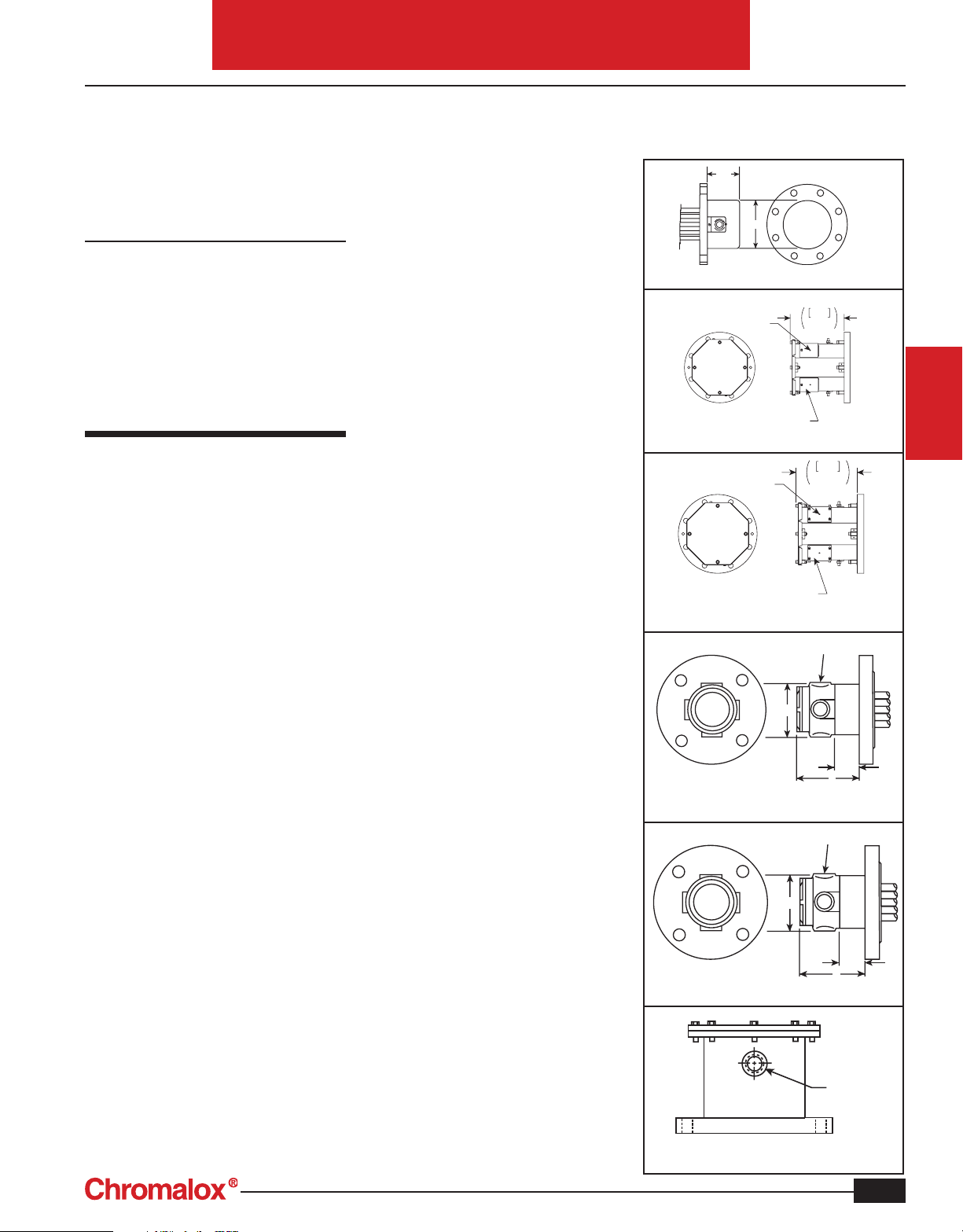
Typical Terminal Enclosures
3-1/2"
6-3/4"
E1 — General Purpose, for up to 5" Flange
Dimple for locating
chassis punched
conduit opening(s)
Removable
Service Entrance
E1 — General Purpose, for 6" and Larger Flange
Dimple for locating
chassis punched
conduit opening(s)
Removable
Service Entrance
E4 — Moisture Resistant Enclosure
with Gasket 6" and Larger
E4 — Moisture Resistant Enclosure
with Gasket up to 5" Flange
E2 — Explosion Proof Enclosure up to 5" Flange
3-3/4"
3-3/4"
263
10-3/8
267
10-1/2"
1" Conduit Outlet
1" Conduit Outlet
5
1-1/2"
1-1/2"
5
CIRCULATION
HEATERS
Conduit
E2 — Explosion Proof Enclosure
for 6" and Larger Flange
Hub
C-5
Circulation Heaters
Terminal
Enclosures
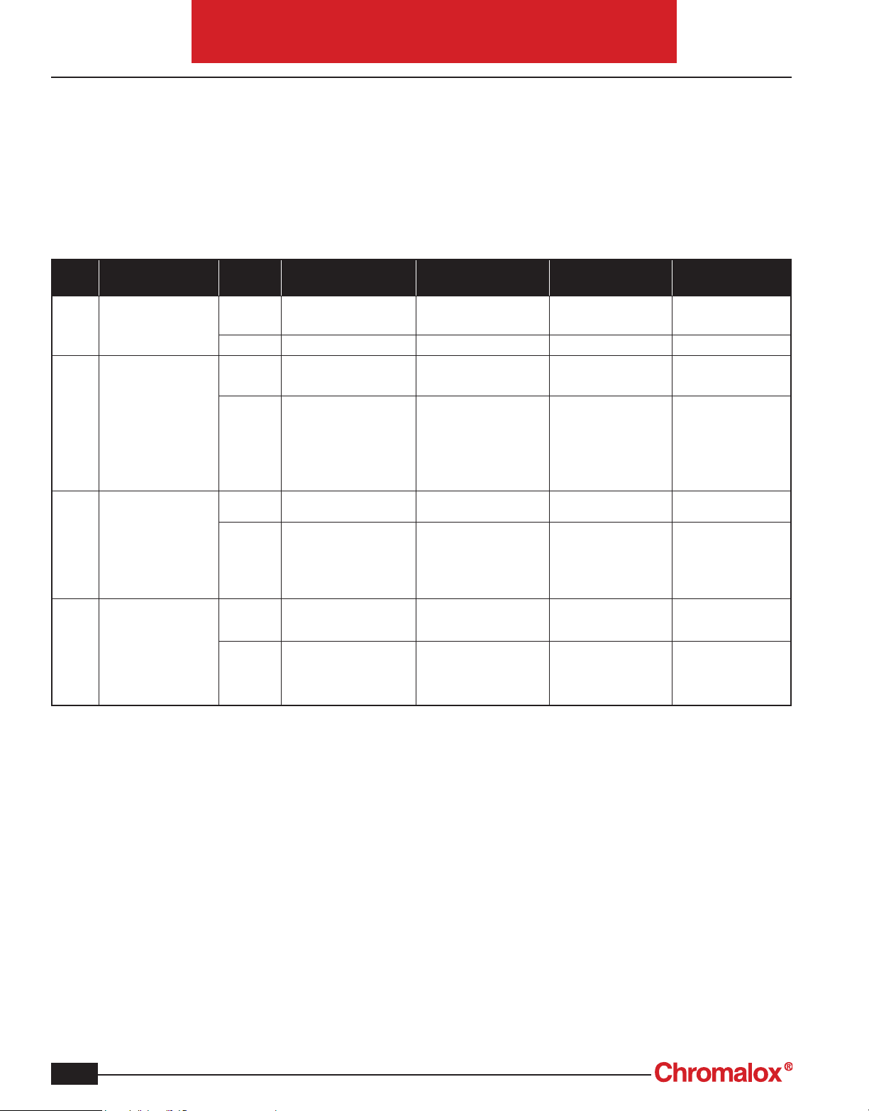
Third Party Specifications by Housing Style
Circulation
Model Purpose
E1 GeneralPurpose Generic
E4* MoistureResistant
E2 MoistureResistant/
E4
Flange
8"-12"
12"-18"
*WARNING: Addition of sparking devices such as a Thermostat to an E4 housing will annul hazardous area rating.
Note: Temps over T3
(200°C) require standoffs for third party
listing. Refer to IECex
& ATEX certifs. for
standoff dimensions
ExplosionProof
ExdIIB+H2T1toT6
Note:Temps over T4
(135°C) require standoffs for third party
listing. Refer to IECex
& ATEX certifs. for
standoff dimensions
MoistureResistant/
Size
3"-8"
ExplosionProof
ExdIIB+H2T1toT6
540°C,600°C
ATEX IIC Labeling
CFP4, CFP8, CFP12
Refer to European
Reference
Catalog
Agency (s)
Ratings General Duty Only General Duty Only General Duty Only General Duty Only
Generic
Agency (s)
Ratings Class I Div. 2,
Generic
Agency (s)
Ratings Class I, Div. 1
Generic
Agency (s)
Ratings II 2 G EEx de IIC T1 to
Designation(s)
NEMA 1, NEC
UL/CSAus
NEMA 4
UL / CSAus
Groups B, C, D
Groups E, F: 200°C
(T3)
Group G 165°C (T3B)
Class I Zone 2 AEx nA II
T1 to T6
CSAus CSA ATEX IECex
Groups B,C & D
Class II, Div. 1
Groups E, F & G
Class I Zone 1
AEx d IIB + H2 T1 to T6
North American
Canadian
Designation(s)
NEMA 1 IP32
CSA
NEMA 4
CSA
Class I Div. 2,
Groups B, C, D
Class II Division 2,
Groups E, F: 200°C
(T3)
Group G 165°C (T3B)
Class I Zone 2
Ex nA II T1 to T6
Class I, Div. 1
Groups B,C &D
Class II, Div. 1
Groups E, F & G
Class I Zone 1
Ex d IIB + H2 T1 to T6
European
Designation(s)
IP32
CE: Manufacturer’s
Declaration
IP66
CE: Manufacturer’s
Declaration
II 3 G Ex nA II T1 to T6 Ex nA II T1 to T6
I 2 G EEx d IIB+H2 T1
to T6
ITS
ATEX
T6, 540°C, 600°C
International
Designation(s)
CE: Manufacturer’s
Declaration
IP66
CE: Manufacturer’s
Declaration
Ex d IIB+H2 T1 to T6
IECex
Ex de IIC T1 to T6
540°C, 600°C
C-6
Circulation
Circulation Heaters
Terminal Enclosures
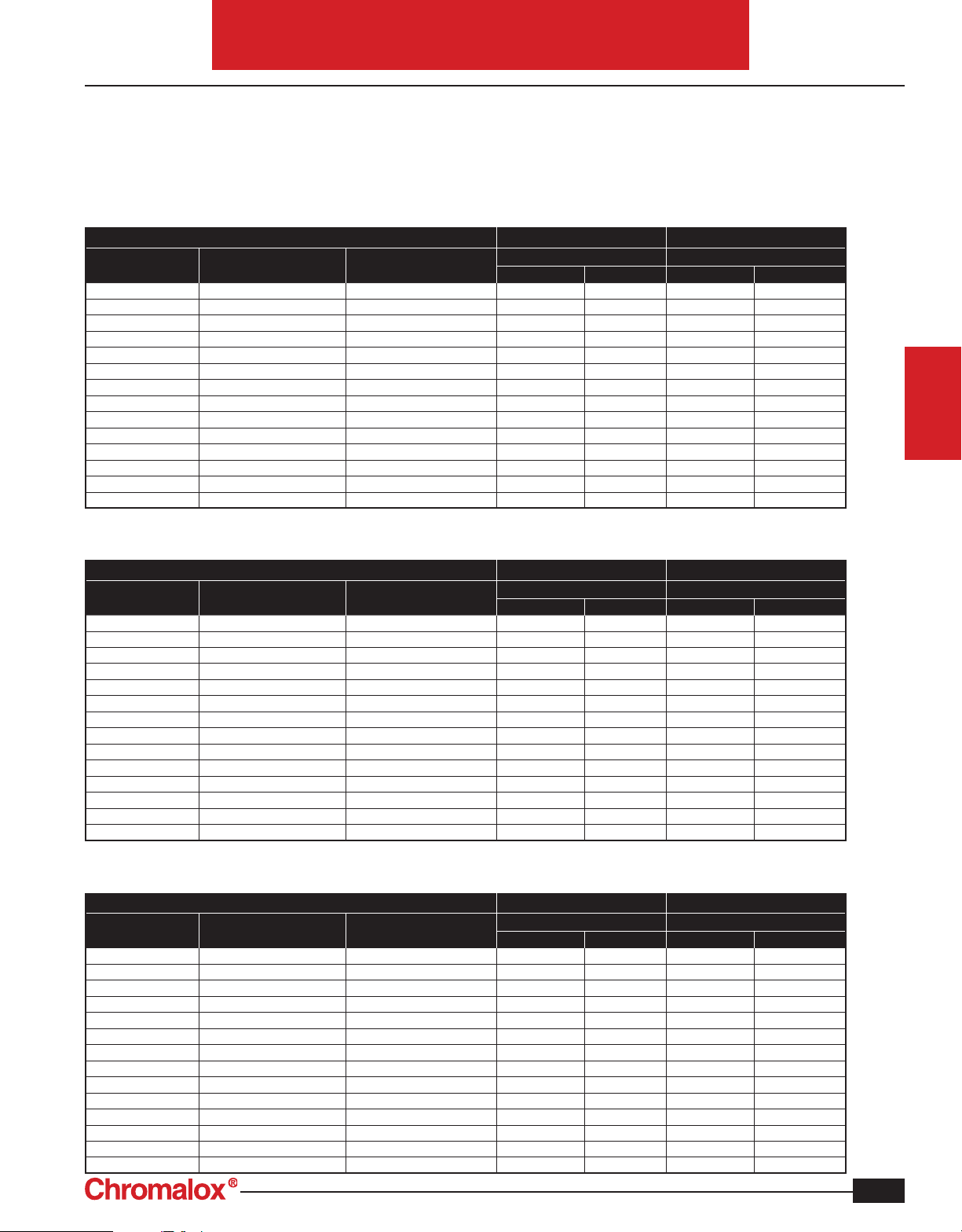
ATEX/IECEx/CSA Zone Classification Selection chart for terminal enclosure
standoff dimension based on 30°C rise over 40°C ambient
70°C Cable Supply
Temperature Code Wet Face Temperature: °F Wet Face Temperature: °C
T6 185 85 3 76 1 25
T5 212 100 3 76 2 50
T4A 248 120 5 127 3 76
T4 275 135 6 152 3 76
T3C 320 160 7.5 191 4 102
T3B 329 165 7.5 191 4 102
T3A 356 180 7.5 191 5 127
T3 392 200 9 229 5 127
T2D 419 215 9 229 5 127
T2C 446 230 9 229 6 152
T2B 500 260 10.5 267 6 152
T2A 536 280 10.5 267 6 152
T2 572 300 10.5 267 7.5 191
T1 842 450 13.5 343 9 229
Vertical Heater Orientation Horizontal Heater Orientation
Minimum Standoff Dimension Minimum Standoff Dimension
Inches mm Inches mm
CIRCULATION
HEATERS
ATEX/IECEx/CSA Zone Classification Selection chart for terminal enclosure
standoff dimension based on 10°C rise over 60°C ambient
70°C Cable Supply
Temperature Code Wet Face Temperature: °F Wet Face Temperature: °C
T6 185 85 9 229 6 152
T5 212 100 10.5 267 7.5 191
T4A 248 120 12 305 7.5 191
T4 275 135 12 305 7.5 191
T3C 320 160 12 305 7.5 191
T3B 329 165 12 305 9 229
T3A 356 180 13.5 343 9 229
T3 392 200 15 381 9 229
T2D 419 215 15 381 10.5 267
T2C 446 230 15 381 10.5 267
T2B 500 260 16.5 419 10.5 267
T2A 536 280 18 457 10.5 267
T2 572 300 18 457 10.5 267
T1 842 450 24 610 12 305
Vertical Heater Orientation Horizontal Heater Orientation
Minimum Standoff Dimension Minimum Standoff Dimension
Inches mm Inches mm
CSA Class and Division Classification Selection chart for terminal enclosure
standoff dimension based on 85°C rise over 40°C ambient
125°C Cable Supply
Temperature Code Wet Face Temperature: °F Wet Face Temperature: °C
T6 185 85 0 0 0 0
T5 212 100 0 0 0 0
T4A 248 120 0 0 0 0
T4 275 135 0 0 0 0
T3C 320 160 2 50 0 0
T3B 329 165 2 50 0 0
T3A 356 180 4 102 2 50
T3 392 200 4 102 2 50
T2D 419 215 4 102 2 50
T2C 446 230 4 102 2 50
T2B 500 260 6 152 4 102
T2A 536 280 6 152 4 102
T2 572 300 6 152 4 102
T1 842 450 7.5 191 6 152
Vertical Heater Orientation Horizontal Heater Orientation
Minimum Standoff Dimension Minimum Standoff Dimension
Inches mm Inches mm
C-7
 Loading...