

Page 1
JOB NAME:
____________________________________________________________________________________________
LOCATION:
____________________________________________________________________________________________
ARCHITECT:
____________________________________________________________________________________________
ENGINEER:
______________________________________________________________________________________________
CONTRACTOR:
__________________________________________________________________________________________
SUBMITTED BY:
__________________________________________________________________________________________
DATE:
__________________________________________________________________________________________________
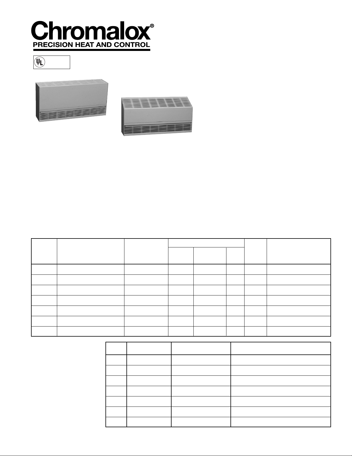
SUBMITTAL SHEET
CAF-12 & CCAS-12
Architectural
Convection Heaters
Capacities
750 w/ft. - 1
500W, 3000W, 4500W, & 6000W
562 w/ft. - 1125W, 1687W, 2250W, 3375W & 4500W
Single Phase Voltage
208V, 240V & 277V
Three Phase Voltage
208V & 480V
Heater Lengths Inches
24.3”, 48.3”, 72.3”, 84.3” & 96.3”
LISTED
PF920-1
HEATER
CATALOG
QTY. NUMBER TAG KW VOLTS Ø AMPS BUILT-IN-CONTROLS
QTY. CATALOG NO. TAG DESCRIPTION
ACCESSORIES
AND
CONTROLS
FILE #E171404
CERTIFIED
FILE LR39591
Chromalox • 103 Gamma Drive Ext. • Pittsburgh, Pennsylvania 15238 • Telephone: 412-967-3800 • Fax: 412-967-5148
© 2002 Chromalox, Inc.
CAF-12
CCAS-12
Page 2
Sample Specifications Logic
CAF-12 Series
Construction
Heaters shall be 12” high, 5
3
/4” deep, with the top and front constructed of extruded aluminum equivalent in strength to 14 gauge steel. The inlet grill shall be interchangeable,
front or bottom, and outlet grill located on the heater top. Cabinet back and bottom to be
fabricated from satin coat steel with multiple knock outs for convenient power connection. Endcaps to be field removable for continuous heater installation.
Color
Color shall be _____________________ (Standard White or Almond. Clear and Bronze
40 available).
Finish
Painted finish shall be hybrid polyester epoxy powder coat process. Clear and Bronze 40
are anodized aluminum finishes.
Heating Element
Heating element to be heavy duty, corrosion resistant, stainless steel sheath, enclosing a
nickel chromium element imbedded in compacted mineral insulation. Aluminum fins are
to be positively staked to the surface and provide superior heat transfer. Element is to be
located in a floating suspension system to eliminate expansion noise.
Controls
(Optional) Heaters to include built-in tamper proof thermostat mounted in the ________
(left or right) terminal box. Built-in low voltage control to be located in the right hand terminal box. Built in disconnect switch is to be located in the right hand terminal box.
Power connection to be made at either the right or left end of the heater. A continuous
wireway to be standard to facilitate continuous installation of multiple heaters.
Thermal Protection
A linear high temperature thermal cutout shall be provided for the full length of the heating element.
ARCHITECTURAL ENGINEER SUGGESTED SPECIFICATIONS
CAF12 B 2 15 21 02 A9 S
Series *Bottom 2’ 1500W 208V/1P White Built-in DP tamperproof Finished
Inlet Length hydraulic thermostat Back
*Note: F = Front inlet
B = Bottom inlet
Specification Guide
Available Voltages Length Weight
Cat. No. Watts BTU 1 Phase 3 Phase (in.) (lbs.)
Standard Density 750 w/ft.
CAF12F215 1500 5118 208, 240, 277 208, 480 24.3 50.9
CAF12F430 3000 10236 208, 240, 277 208, 480 48.3 77.7
CAF12F645 4500 15354 208, 240, 277 208, 480 72.3 104.5
CAF12F860 6000 20472 208, 240, 277 208, 480 96.3 131.3
Low Density 562 w/ft.
CAF12F211 1125 3838 208, 240, 277 208 24.3 50.9
CAF12F316 1687 5756 208, 240, 277 208, 480 36.3 64.3
CAF12F422 2250 7677 208, 240, 277 208, 480 48.3 77.7
CAF12F633 3375 11515 208, 240, 277 208, 480 72.3 104.5
CAF12F845 4500 15354 208, 240, 277 208, 480 96.3 131.3
1. Specify desired voltage, finish and control option from tables.
2. For bottom inlet version replace “F” in catalog number with “B”.
3. End caps are included with heaters.
4. Consult factory for custom finish requirements.
Control Options (Factory Installed)
Accessories (Field Installed)
Voltage Selection
Finish Selection
Code Voltage/Phase
21 208/1
23 208/1
31 240/1
41 277/1
73 480/3
Painted Anodized
68 Almond 07 Bronze
02 White 10 Clear
Code Description
A9 Built-in DP tamperproof hydraulic thermostat 208 - 277V
A3 Built-in 3P tamperproof hydraulic thermostat for 3 phase 208 - 480V
A4 Build-in 24V low voltage relay for 1P voltages 208-277V
A5 Built-in 24V low voltage relay and transformer for 1P voltages 208 - 277V
A6 Built-in 24V contactor less transformer for 3P voltages 208 - 480V
A7 Built-in 24V contactor and transformer for 3P voltages 208 - 480V
A8 Built-in disconnect switch, rated 277V20A
B9 Built-in DP tamperproof thermostat and disconnect
B3 Built-in 3P tamperproof thermostat and disconnect
Cat. No. Description
ALF121C90 Inside 90 degree corner
ALF120C90 Outside 90 degree corner
Filler Sections Consult factory for available sizes
Specify finish code when ordering accessories.
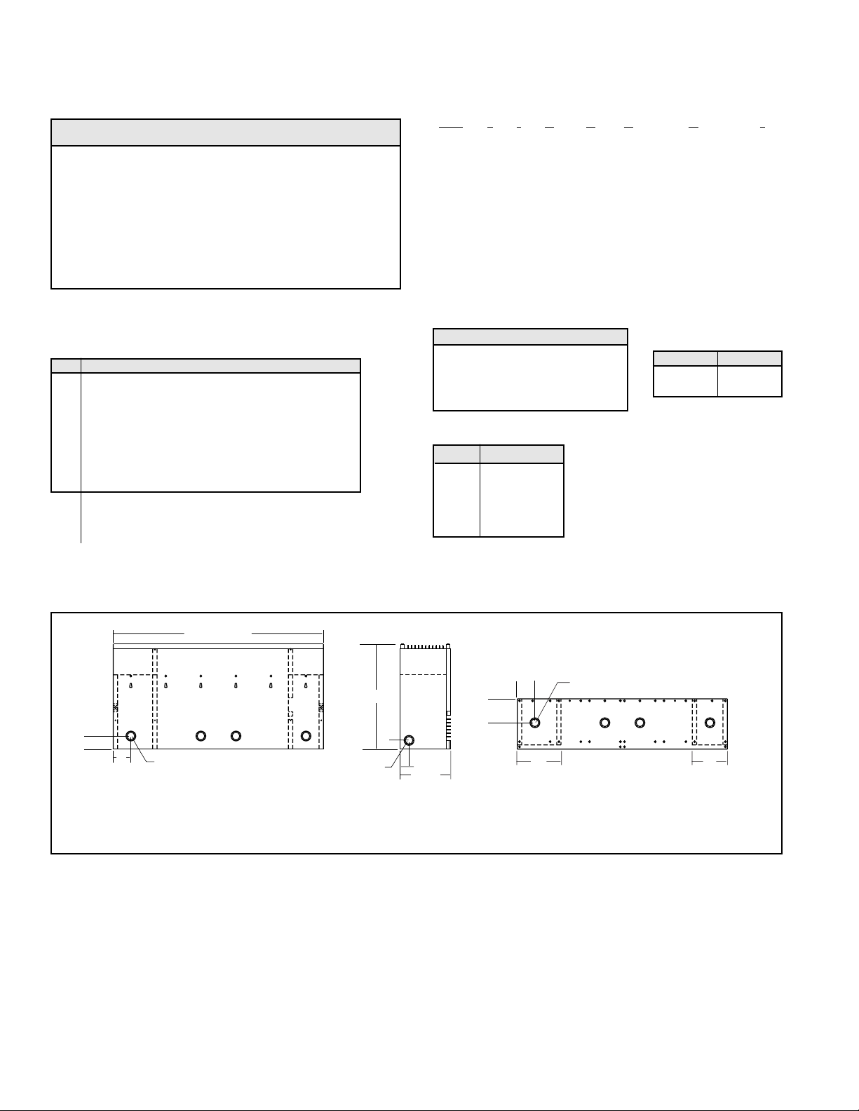
CAF12 SERIES
Architectural Convection Heater
Cabinet Features
Add “S” or “W” to end of cat. no. for:
W — Pedestal and finished back
S — Finished painted back
Low watt density ranges available — consult factory.
"L" LENGTH
12"
1-1/2"
2"
7/8 - 1-1/8"
DIA K.O.
7/8 - 1-1/8"
DIA K.O.
BACK VIEW
SIDE VIEW (Less Endcap)
2"
7/8 - 1-1/8"
DIA K.O.
2-3/4"
1"
1"
5-3/4"
5"
TERMINAL BOX
4"
TERMINAL BOX
BOTTOM VIEW
(Front Inlet Version Shown)
Page 3

ARCHITECTURAL ENGINEER SUGGESTED SPECIFICATIONS
CCAS12 SERIES
Architectural Slope Top Heater
Sample Specifications Logic
CCAS12 B215 21 02 A9 S
Series *Bottom 2’ 1500W 208V/1P White Built-in SP tamperproof Finished
Inlet Length hydraulic thermostat painted
back
*Note: F = Front inlet
B = Bottom inlet
Specification Guide
Available Voltages Length Weight
Cat. No. Watts BTU 1 Phase 3 Phase (in.) (lbs.)
Standard Density 750 w/ft.
CCAS12F215 1500 5118 208, 240, 277 208, 480 24.3 50.9
CCAS12F430 3000 10236 208, 240, 277 208, 480 48.3 77.7
CCAS12F645 4500 15354 208, 240, 277 208, 480 72.3 104.5
CCAS12F860 6000 20472 208, 240, 277 208, 480 96.3 131.3
Low Density 562 w/ft.
CCAS12F211 1125 3838 208, 240, 277 208 24.3 50.9
CCAS12F316 1687 5756 208, 240, 277 208, 480 36.3 64.3
CCAS12F422 2250 7677 208, 240, 277 208, 480 48.3 77.7
CCAS12F633 3375 11515 208, 240, 277 208, 480 72.3 104.3
CCAS12F845 4500 15354 208, 240, 277 208, 480 96.3 131.3
1. Specify desired voltage, finish and control option from tables.
2. For bottom inlet version replace “F” in catalog number with “B”.
3. End caps are included with heaters.
4. Consult factory for custom finish requirements.
Control Options (Factory Installed) Accessories (Field Installed)
Voltage Selection
Finish Selection
Code Voltage/Phase
21 208/1
23 208/1
31 240/1
41 277/1
73 480/3
Painted Anodized
68 Almond 07 Bronze
02 White 10 Clear
Code Description
A9 Built-in DP tamperproof hydraulic thermostat 208 - 277V
A3 Built-in 3P tamperproof hydraulic thermostat for 3 phase 208 - 480V
A4 Build-in 24V low voltage relay for 1P voltages 208-277V
A5 Built-in 24V low voltage relay and transformer for 1P voltages 208 - 277V
A6 Built-in 24V contactor less transformer for 3P voltages 208 - 480V
A7 Built-in 24V contactor and transformer for 3P voltages 208 - 480V
A8 Built-in disconnect switch, rated 277V20A
B9 Built-in DP tamperproof thermostat and disconnect
B3 Built-in 3P tamperproof thermostat and disconnect
Cat. No. Description
ALS121C90 Inside 90 degree corner
ALS120C90 Outside 90 degree corner
Filler Sections Consult factory for available sizes
Specify finish code when ordering accessories.
Cabinet Features
Add “S” or “W” to end of cat. no. for:
W — Pedestal and finished back
S — Finished painted back
Low watt density ranges available — consult factory.
CCAS-12 Series
Construction
Heaters shall be low profile 12” high, 5
3
/4” deep, with the top and front constructed of
extruded aluminum equivalent in strength to 14 gauge steel. The inlet grill shall be interchangeable, front or bottom, and outlet grill located on the heater top. Cabinet back and
bottom to be fabricated from satin coat steel with multiple knock outs for convenient
power connection. Endcaps to be field removable for continuous heater installation.
Color
Color shall be _____________________ (Standard White or Almond. Clear and Bronze
40 available).
Finish
Painted finish shall be hybrid polyester epoxy powder coat process. Clear and Bronze 40
are anodized aluminum finishes.
Heating Element
Heating element to be heavy duty, corrosion resistant, stainless steel sheath, enclosing a
nickel chromium element imbedded in compacted mineral insulation. Aluminum fins are
to be positively staked to the surface and provide superior heat transfer. Element is to be
located in a floating suspension system to eliminate expansion noise.
Controls
(Optional) Heaters to include built-in tamper proof thermostat mounted in the ________
(left or right) terminal box. Built-in low voltage control to be located in the right hand terminal box. Built in disconnect switch is to be located in the right hand terminal box.
Power connection to be made at either the right or left end of the heater. A continuous
wireway to be standard to facilitate continuous installation of multiple heaters.
Thermal Protection
A linear high temperature thermal cutout shall be provided for the full length of the heating element.
"L" LENGTH
12"
1-1/2"
2"
7/8 - 1-1/8"
DIA K.O.
7/8 - 1-1/8"
DIA K.O.
BACK VIEW
SIDE VIEW (Less Endcap)
2"
7/8 - 1-1/8"
DIA K.O.
2-3/4"
1"
1"
5-3/4"
5"
TERMINAL BOX
4"
TERMINAL BOX
BOTTOM VIEW
(Front Inlet Version Shown)
Page 4

00-000
 Loading...