

Page 1

DIVISION 4 SECTION
CAB
SALES
REFERENCE
SERVICE REFERENCE
161-048224-001
Chromalox
®
(Supersedes PF412-6)
Installation, Operation
and
RENEWAL PARTS INDENTIFICATION
PF412-7
© 2010 Chromalox, Inc.
Type CAB and CABB
Forced Air Duct Heaters
Model
Dimensions (In.)
(Note 1) (Note 2)
Weight
Volts Phase kW
No. No.
(Lbs.) Finstrips Ckts.
ABC
CAB-62 CAB-611
25
120, 208,
1 or 3 6 6 1 10-3/4 15-7/8 11-1/2
CABB-62 CABB-611 240 or 480
CAB-122 CAB-1211
35 208, 240 or 480 1 or 3 12 9 1 15-3/8 18-1/2 14-1/8
CABB-122 CABB-1211
CAB-152 CAB-1511
40 208, 240 or 480 1 or 3 15 9 1 15-3/8 21-5/8 17-1/4
CABB-152 CABB-1511
CAB-202 CAB-2011
55
208 or 240 3
20 12 1 20-1/8 21-5/8 17-1/4
CABB-202 CABB-2011 480 1 or 3
CAB-252 CAB-2511
65
208 or 240 3
25 12 1 20-1/8 26-1/8 21-3/4
CABB-252 CABB-2511 480 1 or 3
—— CABB-3011 75 480 3 30 18 2 29-1/2 21-5/8 17-1/4
CAB-402 CAB-4011
90
208 or 240 3
40 18 2 29-1/2 27-3/8 23
CABB-402 CABB-4011 480 1 or 3
CAB-502 CAB-5011
110
208 or 240 3
50 18 2 29-1/2 33-1/8 28-3/4
CABB-502 CABB-5011 480 1 or 3
CAB-752 CAB-7511
200
208 or 240 3
75 27 3 44-7/16 42-1/8 37-3/4
CABB-752 CABB-7511 480 1 or 3
CAB-1002 CAB-10021
220
208 or 240 3
100 27 3 44-7/16 47-1/2 43-1/8
CABB-1002 CABB-10021 480 1 or 3
1. Iron sheath strip heaters — for sheath temperatures to 750˚F.
2. Chrome steel sheath strip heaters — for sheath temperatures to 950˚F.
Sensitive Bulb of
Thermostat
2 Holes 5/16-18 Tapped,
Each Side For Mounting
A
B
C
21/32
1-9/16”
2-1/4”
3-5/8”
Type CABB
Type CAB
3/4”
4-1/4”
2-1/4”
Special Cover for Side
or Bottom Terminals
Specifications –
Page 2
GENERAL
WARNING: This heater is not intended for use in
hazardous atmospheres where flammable vapors,
gases, liquids or other combustible atmospheres are
present as defined in the National Electrical Code.
Failure to comply can result in explosion or fire.
1. Heat Construction Characteristics:
A. Finstrip
®
elements of either rust resisting iron or chrome
steel sheath, and aluminized steel fins.
B. 14 gage cold rolled steel frame painted with a black pow-
der coat paint.
C. Internal electrical connections consist of buss bars and
jumper straps of either Mn-Ni or Monel.
D. Field wiring terminals of heavy duty 3/8” diameter bolts of
either brass (iron sheath units) or stainless steel (chrome
steel sheath units) with hardware are provided for field
wiring connections.
2. Maximum temperatures — Type CAB and CABB air duct
heaters can generally be used at the following maximum temperatures provided the minimum air velocity is maintained
uniformly through the heater. Table 2 is based on the standard
unit of 26 watts per square inch. If unit watt density is lower,
higher temperatures can be achieved. If higher watt densities
are used, outlet air temperature should be lowered.
3. Several heaters may be mounted in tandem as long as proper
controls are used to limit the maximum temperature attained. See
pressure drop curve G112S1 for effect of mounting in tandem.
4. Overtemperature protection — A thermal cutout should be
installed at the exhaust side of the heater for protection against
low airflow conditions.
INSTALLATION
WARNING: Hazard of Electric Shock. Disconnect
all power before installing heater.
1. Install heater into desired location in air duct with terminals
on bottom.
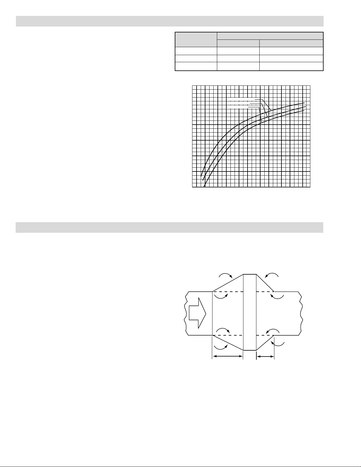
2. For installation where the duct heater is larger than the ductwork, the duct area must be increased by a sheet metal transition. The slope of the transition piece on the upstream side is
limited to 30˚ as indicated in Figure 2. On the leaving side, the
slope should not be more than 45˚.
3. Make sure ductwork is of sufficient strength to contain the
heater. Refer to Table 1 for heater weights. Consult your local
sheet metal contractor if in doubt.
4. Two holes 5/16-18 tapped are located on each side of the
heater for mounting.
5. Air velocity must be sufficient enough to prevent element failure. See Table 2 for guidelines.
6. For protection against accidental air stoppage, mount a thermal cutout on the exhaust side of the heater.
7. Insert thermal cutout sensitive bulb through duct and attach to
heater case with mounting clips provided.
8. DANGER: Hazard of Fire. Since these heaters are capa-
ble of developing high temperatures, extreme care should be
taken to:
a. Avoid installing heaters in an atmosphere containing com-
bustible gases and vapors.
b. Avoid contact between heater and combustible material.
c. Keep combustible material far enough away to be free of
the effects of high temperatures.
Air Velocity Max. Outlet Air Temp. (˚F)
(Ft./Sec.) Iron Sheath Chrome Steel Sheath
4 — 200
9 90 330
16 220 440
Air
Flow
30˚
Max
30˚
45˚
45˚
Duct Heater
4 Ft. Min.
4 Ft. Min.
1.0
.9
.8
.7
.6
.5
.4
.3
.2
.1
.09
.08
.07
.06
.05
.04
.03
.02
.01
.009
.008
.007
.006
.005
.004
.003
.002
300
600
900
1200 1500
1800 2100
Triple Row of CAB
Double Row
Single Row
Velocity of Air F.P.M. (STD. Air)
Curve G112S1 - Resistance to Air Flow
Pressure Drop - In. of Water (LBS/In
2
= IN. of Water x 0.036)
Table 2
Figure 2
Page 3

WIRING
WARNING: Hazard of Electric Shock. Any installation
involving electric heaters must be effectively grounded in accordance with the National Electrical Code to
eliminate shock hazard.
1. All wiring should be done in accordance with the National
Electrical Code and with local codes by a qualified person.
2. Connect air heaters to same line voltage, phase and frequency
as on heater nameplate.
3. Teflon insulated nickel plated copper wire or buss bar is rec-
ommended for power connections to heater terminals and for
wiring runs in heated zones. When ambient temperature in
heated zone exceeds that for which insulated wire is recommended use bare nickel-plated copper with porcelain beads,
tubing or buss bar. Consult local Chromalox representative.
4. Users should install adequate back-up controls and safety
devices with their electric heating equipment. Selection of
controls, thermostat, SCR units, contactors and etc. depends
on the degree of accuracy required, reliability, electrical rating
of heater and economic considerations.
5. Below is an example of standard CAB 122 480V 3P 12 kW
wired with recommended back-up controls (Figure 3).
OPERATION
WARNING: Users should install adequate back-up
controls and safety devices with their electric
heating equipment. Where the consequences of
failure may be severe, back-up controls are essential. Although the safety of the installation is the
responsibility of the user, Chromalox will be glad
to assist in making equipment recommendations.
1. Do not operate heaters at voltages in excess of that stamped
on the heater since excess voltage will shorten heater life.
MAINTENANCE
WARNING: Hazard of Severe Shock. Disconnect all
power to heater before servicing or replacing heaters.
1. Periodically clean terminals and terminal covers of dust and
corrosion to maintain good electrical connections and to permit rapid heat dissipation. Use airblast, and be careful to avoid
damage to mica insulation.
2. Check for loose terminal connections.
Fused Switch
480V
Power
Supply
Heater
Contactor
Thermal Cutout
Fan
Motor
120/240
Control
Circuit
Figure 3 - Wiring Diagram
Page 4

2150 N. RULON WHITE BLVD., OGDEN, UT 84404
Phone: 1-800-368-2493 www.chromalox.com
RENEWAL PARTS IDENTIFICATION
Model kW
Heating Element
120 Volt 208 Volt 240 Volt 480 Volt
CAB-62
6
117-013851-001 (6) 117-013851-002 (6) 117-013851-003 (6) 117-013851-004 (6)
CABB-62
CAB-611
117-013852-001 (6) 117-013852-002 (6) 117-013852-003 (6) 117-013852-004 (6)
CABB-611
CAB-122
12
—— 117-013851-006 (9) 117-013851-007 (9) 117-013851-008 (9)
CABB-122
CAB-1211
—— 117-013852-006 (9) 117-013852-007 (9) 117-013852-008 (9)
CABB-1211
CAB-152
15
—— 117-013851-010 (9) 117-013851-011 (9) 117-013851-012 (9)
CABB-152
CAB-1511
—— 117-013852-010 (9) 117-013852-011 (9) 117-013852-012 (9)
CABB-1511
CAB-202
20
—— 117-013851-010 (12) 117-013851-011 (12) 117-013851-012 (12)
CABB-202
CAB-2011
—— 117-013852-010 (12) 117-013852-011 (12) 117-013852-012 (12)
CABB-2011
CAB-252
25
—— 117-013851-014 (12) 117-013851-015 (12) 117-013851-016 (12)
CABB-252
CAB-2511
—— 117-013852-014 (12) 117-013852-015 (12) 117-013852-016 (12)
CABB-2511
CABB-3011 30 —— —— —— 117-013852-012 (18)
CAB-402
40
—— 117-013851-018 (18) 117-013851-019 (18) 117-013851-020 (18)
CABB-402
CAB-4011
—— 117-013852-018 (18) 117-013852-019 (18) 117-013852-020 (18)
CABB-4011
CAB-502
50
—— 117-013851-022 (18) 117-013851-023 (18) 117-013851-024 (18)
CABB-502
CAB-5011
—— 117-013852-022 (18) 117-013852-023 (18) 117-013852-024 (18)
CABB-5011
CAB-752
75
—— 117-013851-026 (27) 117-013851-027 (27) 117-013851-028 (27)
CABB-752
CAB-7511
—— 117-013852-026 (27) 117-013852-027 (27) 117-013852-028 (27)
CABB-7511
CAB-1002
100
—— 117-013851-030 (27) 117-013851-031 (27) 117-013851-032 (27)
CABB-1002
CAB-10021
—— 117-013852-030 (27) 117-013852-031 (27) 117-013852-032 (27)
CABB-10021
Number in parenthesis indicates total quantity in unit.
Terminal Cover — 306-021921-001
Bulb Mounting Strap — 283-033234-001
Limited Warranty:
Please refer to the Chromalox limited warranty applicable to this product at
http://www.chromalox.com/customer-service/policies/termsofsale.aspx.
 Loading...