

Page 1
Hardware Instruction Manual
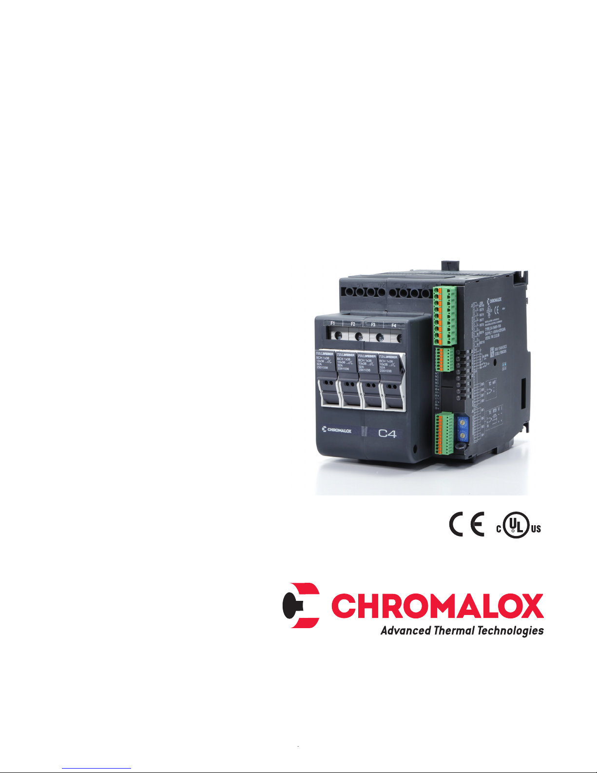
C4
4-Channel SCR Power Controller
with Independent PID Control
PK544
0037-75573
April 2018
i
Page 2

Table of Contents
Important Safeguards ............................................................................................................. 1
1. Initial Instructions .............................................................................................................. 2
1.1 General Description ................................................................................................................................. 2
1.2 Features ................................................................................................................................................... 2
1.3 Product Inspection .................................................................................................................................. 2
2. Dimensions & Weights ...................................................................................................... 3
3. Installation - Mounting ...................................................................................................... 4
4. Installation - Wiring ........................................................................................................... 5
5. Emission, Immunity and Safety Standards ..................................................................... 6
6. Controller Overview .......................................................................................................... 7
6.1 Layout ................................................................................................................................................... 7
6.2 Cooling Fan ............................................................................................................................................. 8
6.3 Inserting a New Field Bus Interface Card ................................................................................................ 8
7. Connections and Indication ............................................................................................. 9
7.1 Power Connections ................................................................................................................................. 9
7.2 Power Wiring Considerations .................................................................................................................. 9
7.3 Input & Output Connections .................................................................................................................. 10
7.4 LED Logic .............................................................................................................................................. 10
7.5 Rotary Switches .................................................................................................................................... 11
7.6 Connector Detail .................................................................................................................................... 11
7.6.1 Connector J1/J1a ......................................................................................................................... 11
7.6.2 Connector J2 ................................................................................................................................ 14
7.6.3 Connector J3 ................................................................................................................................ 15
7.6.4 Connector J4 ................................................................................................................................ 16
7.7 DIP-Switch Configuration ...................................................................................................................... 17
7.8 Serial Communication Ports .................................................................................................................. 18
7.8.1 Port1 (Standard Local Bus) ..........................................................................................................18
7.8.2 Port2 (Optional Fieldbus) .............................................................................................................. 19
7.8.3 Connection Example: Communication Port ................................................................................. 25
8. Load Connection Examples ........................................................................................... 29
8.1 4 Single Phase Loads, 3- Phase Line with Neutral ............................................................................... 31
8.1 4 Single Phase Loads, 3- Phase Line without Neutral .......................................................................... 31
8.3 Two 3-Phase Loads, Closed Delta ........................................................................................................32
8.4 Two 3-Phase Loads, Star (Wye) without Neutral ................................................................................... 32
8.5 One 3-phase Load Active, One 3-Phase Load Inactive, Wye without Neutral ...................................... 33
8.6 One 3-Phase Load, Inside Delta ............................................................................................................ 33
9. Inductive and Transformer Coupled Load Guidelines ................................................. 34
10. Communications Port (Modbus RTU/RS485) ............................................................... 34
11. Autobaud Function .......................................................................................................... 35
11.1 Autobaud Port 1 Sequence ................................................................................................................... 35
11.2 11.2 Autonode Sequence for Fieldbus Use ........................................................................................... 35
12. Specifications .................................................................................................................. 36
13. Ordering Information ....................................................................................................... 40
14. Configuration and Programming ................................................................................... 41
15. Accessories ..................................................................................................................... 41
ii
Page 3
Important Safeguards
HIGH VOLTAGE (up to 480 VAC) is used in the
operation of this equipment; DEATH ON CONTACT may result if personnel fail to observe
safety precautions.
Learn the areas containing high-voltage connections when installing or operating this
equipment.
Be careful not to contact high-voltage connections when installing or operating this equipment.
Before working inside the equipment, turn
power off and ground all points of high potential before touching them.
The owner/installer must provide all necessary
safety and protection devices and follow all
current electrical wiring standards and regulations. Failure to do so may compromise the
integrity of the controller and/or cause product
failure resulting in a safety risk to operational
and service personnel.
This controller utilizes a heat sink which is designed to cool the unit during operation. Under no circumstance should air flow around the
controller be compromised in any way. Failure
to do so may result in the overheating of the
controller, product failure, product temperatures and even fire.
During continuous operation, the heat sink can
reach very high temperatures, and keeps a
high temperature even after the unit is turned
off due to its high thermal inertia.
Higher voltages may be present. DO NOT work
on the power section without first cutting out
electrical power to the panel. Failure to do so
may cause serious injury or death.
ELECTRIC SHOCK HAZARD: Any installation involving control equipment must be performed
by a qualified person and must be effectively grounded in accordance with the National
Electrical Code to eliminate shock hazard.
1
Page 4

1. Initial Instructions
1.1 General Description
The C4 is an extremely compact advanced SCR power
controller that provides a unique combination of performance, reliability, and flexibility. The C4 multiple
zone SCR power controller manages both single phase
and 3-phase industrial heating load applications. Load
management options include: Up to 4 independently
controlled single phase loads or one 3-phase/3-leg
load (with or without an additional single phase load) or
up to two 3-phase/2-Leg loads.
Standard features: Output choices range from 30 kW
to 80 kW per unit or from 16 to 40 Amps per zone at
480 Vac (for higher amperages the C4X can be used);
Four universal main process inputs, two digital inputs,
two configurable alarm outputs, Mod-bus RTU/RS485
digital communications, DIN Rail or panel mountable.
Optional features: One or four Current Transformers (input), four analog inputs, integral fuse holder (30
kW & 60 kW only), four configurable outputs, modular
Fieldbus Communication protocols including Modbus
RTU, Modbus TCP, Ethernet IP, EtherCAT, CANopen,
DeviceNet, Profibus, and Profinet. This new Chromalox
controller is the ideal PID and power control solution
for applications demanding high performance, continuous service, preventative maintenance information,
and increasing need for process data and information
for quality and process improvement analysis. Industry
markets such as, but not limited to:
• Packaging
• Plastics Processing; Extrusion; Thermforming; Injection Molding, Welding & Joining
• Semiconductor
• Material Finishing; Paint Booths;
• Textile
• Multiple zoned furnaces; Tunnel Ovens
• Food Processing
1.2 Features
• 30, 60, 80kW controller size capacity (refer to C4X
for higher amperages)
• Solid state relay control
• One or four current transformers
• Fuses-holder (option)
• 4 universal main inputs
• 4 heat/cool independent PID
• 4 main output internally wired to the SSR
• 4 auxiliary analog inputs (option)
• 4 configurable output (option): relay / logic / analog/
TRIAC
• 2 configurable relay alarm output
• 2 digital inputs
• Standard digital communication: Modbus RTU/
RS485
• Optional Fieldbus communication: Profibus DP,
CANopen, DeviceNet, Modbus RTU, Ethernet Modbus TCP, Ethernet IP, EtherCAT, ProfiNET
• DIN rail mounting
• Integrated heat sink and fan
• cULus, CE
1.3 Product Inspection
Immediately after unpacking the unit and prior to installing, check the order code and the other data on
the label attached to the outside of the container and
write them down. If troubleshooting is necessary, you
will need to provide this data to a Chromalox customer
service representative.
Upon removing package, ensure that there is no physical damage to the controller during shipment, and that
the package also contains the “Configuration and Programming” manual.
If there are signs of damage or if any parts are missing,
notify your Chromalox representative immediately.
Read through all installation sections in detail within
this document before installing the C4 on any piece of
equipment or in a control panel enclosure. Spacing requirements must be honored for proper operation and
safety.
2
Page 5
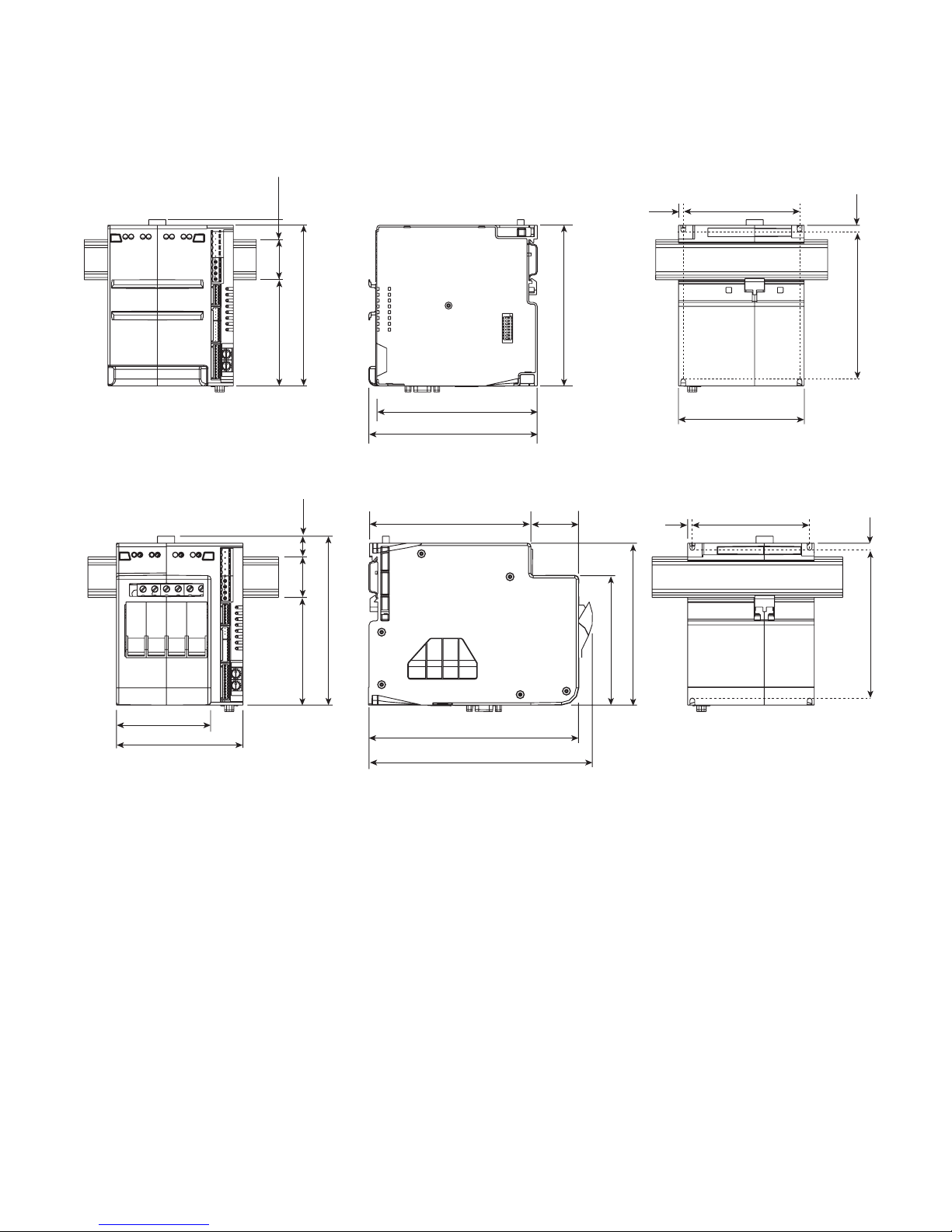
2. Dimensions and Weights
(155)
Models without Fuse Holder
3.85
(92.5)
0.75
(19.6)
1.4
(35)
0.75
(19.5)
5.5
(140)
1.4
(35)
5.75
(147)
5.75
(147)
(140)
5.5
(140)
5.5
1.55
(42)
5.5
(140)
4.4
(111.5)
5.5
(140)
0.16
(4)
0.16
(4)
4
(101.5)
4.3
(109.5)
4
(101.5)
0.16
(4)
5.2
(132)
0.16
(4)
5.2
(132)
3.25
(52
)
4.3
(109.5)
3.65
(92.5)
7.7
7.2
(182)
3
Page 6
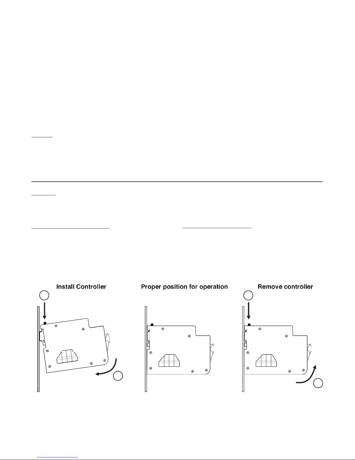
3. Installation
ROTATE
To ensure proper performance, maximum safety and
reliability, it is essential to install the unit correctly. This
includes proper mounting, spacing, hardware and wiring. See below:
• Maximum surrounding air temperature is 40°C in
“Open Type Equipment” which is suitable for use in
pollution degree 2. For temperature >40°C refer to
the Derating Curves.
• Install the unit vertically (max 10° inclination from
vertical axis).
Spacing
To ensure maximum reliability, the device must be correctly installed in the panel in such a way as to obtain
adequate heat exchange between the heat sink and
the surrounding air under conditions of natural convec-
Mounting
C4 Models to be installed on a DIN Rail . Rear panel
dimensions are on previous page.
tion. Under no circumstance shall any component, including cable channels, compromise minimum thermal
spacing dimensions. Air must be able to flow vertically
on the heat sink without any obstacles.
Solid state devices dissipate heat which may impact
installation room temperature. Exchange with external
air or an air conditioner may be necessary to transfer
heat outside the panel.
• Minimum vertical distance between unit and panel
wall: 3.9” (100 mm)
• Minimum horizontal distance between unit and panel wall: 0.8” (20 mm)
• Minimum horizontal distance between adjacent
power control units: 0.4” (10 mm)
To install C4 onto a DIN Rail:
1. Depress DIN mounting spring. u
2. Position controller on the DIN Rail at a slight angle.
3. Lower controller on to DIN Rail. v
4. Release the mounting spring.
1
PRESS
2
ROTATE
To remove from DIN Rail:
1. Depress DIN mounting spring. u
2. Rotate bottom of controller off of the DIN Rail. v
3. Remove from DIN Rail.
1
PRESS
2
4
Page 7

4. Installation – Wiring
This section covers the C4 wiring installation instructions for the power supply, inputs, outputs and interfaces.
CAREFULLY READ THE FOLLOWING WARNINGS
BEFORE INSTALLING THE INSTRUMENT!
Failure to obey these warnings could create
electrical safety and electromagnetic compatibility problems, as well as void the warranty
and cause personal injury or death.
Electrical Power Supply
• The controller DOES NOT have an On/Off switch.
The user must install a switch or isolator that conforms to all codes and electrical safety requirements
(CE mark) to cut off the power supply upstream of
the controller. The switch must be installed in the
immediate vicinity of the controller and with-in
reach of the operator. A single switch can be used
for multiple devices.
• The earth connection must be made with a specific
lead.
• If the product is used in applications with risk of
harm to persons or damage to machines or materials, it MUST be equipped with auxiliary alarm
device(s). It is advisable to provide the ability to
check for tripped alarms during regular operation.
DO NOT install the product in rooms with hazardous (inflammable or explosive) atmosphere; it may
be connected to elements that operate in such atmosphere only by means of appropriate interfaces
that conform to current safety standards..
Notes on Electrical Safety and Electromagnetic
Compatibility
CE MARKING: EMC (electromagnetic compatibility)
conformity in compliance with Directive 2004/108/
CE and following modifications. Series C4 control-
lers are mainly intended for industrial use, installed on
panels or control panels of production process machines or systems. For purposes of electromagnetic
compatibility, the most restrictive generic standards
have been adopted, as shown on the tables.
LV (low voltage) conformity Directive 2006/95/CE.
EMC compliance has been verified with respect to the
information in Tables 1 and 2.
Recommended Installation for purposes of EMC
Instrument power supply
• The power supply for the electronic instrumentation
on the panels must always come directly from a cut/
off device with fuse for the instrument part.
• Electronic instrumentation and electromechanical
power devices such as relays, contactors, solenoids,
etc., MUST ALWAYS be powered by separate lines.
• When the power supply line of electronic instruments is heavily disturbed by switching of SCR power groups or by motors, you should use an isolation
transformer only for the controllers, grounding its
sheathing.
• It is important for the system to be well grounded.
Voltage between neutral and ground must not be > 1
V and resistance must be < 6Ω (Ohms).
• If the grid voltage is highly unstable, use a voltage
stabilizer.
• In proximity of high frequency generators or arc
welders, use adequate grid filters.
• The power supply lines must be separate from instrument input and output lines.
• Supply from Class II or from limited energy sources.
Input and output connections
Before connecting or disconnecting any connection, always check that the power and control cables are isolated from voltage. Appropriate devices must be provided:
fuses or automatic switches to protect power lines.
•
Connected outside circuits must be doubly isolated.
• To connect analog or linear inputs, strain gauges,
TC, RTD, etc., you have to:
• physically separate the input cables from those
of the power supply, outputs, and power connections.
• use braided and shielded cables, with sheath-
ing grounded at a single point.
• To connect the control outputs and alarm outputs
(contactors, solenoids, motors, fans, etc.), install
RC (series of capacitors and resistors) groups parallel to inductive loads that work in AC.
(Note: all condensers must conform to VDE stan-
dards (class X2) and support voltage of at least
220Vac. Resistances must be at least 2W).
• Install a 1N4007 diode parallel to the coil of inductive loads that work in DC.
Installation Notes
Use the extra rapid fuse indicated in Table 15.1 later
in this manual, according to the wiring schematic examples and controller rating. Additionally, the applications with solid state units require a safety automatic
switch to disengage the load power line during certain
alarm events.
5
Page 8

5. Emission, Immunity and Safety Standards
Table 1: EMC Emission
AC semiconductor motor controllers and conductors
for non-motor loads
Emission enclosure compliant in firing mode single
cycle and phase angle if external filter fitted
Table 2: EMC Immunity
Generic standards, immunity standard for
industrial environments
ESD immunity EN 61000-4-2
RF interference immunity
Conducted disturbance immunity
Burst immunity EN 61000-4-4
Surge immunity EN 61000-4-4/5
EN 60947-4-3
EN 60947-4-3
EN 60947-4-3 CISPR-11
EN 55011
4 kV contact discharge
8 kV air discharge
10 V/m amplitude modulated
80 MHz-1 GHz
10 V/m amplitude modulated
1.4 GHz-2 GHz
10 V/m amplitude modulated
0.15 MHz-80 MHz
2 kV power line
2 kV I/O signal line
PPower line-line 1 kV (level 2)
Power line-earth 2kV (level 3)
Signal line-earth 1kV (level 2)
Class A
Group 2
Magnetic fields immunity EN 61000-4-8 100 A/m (level 5)
Voltage dips, short interruptions and voltage
immunity tests
Table 3: LVD Safety
Safety requirements for electrical equipment for
measurement, control and laboratory use
ATTENTION
This product has been designed for class A equipment. Use of the product in domestic environments may cause
radio interference, in which case the user may be required to employ additional noise mitigation methods.
Per UL, the SCCR (Short Circuit Current Rating) is 100kA for models: C4 - XXXXX - 0 - XX Suitable for use on
a circuit capable of delivering not more than 100RMS kA symmetrical, 480VAC when protected only by listed
cartridge fuses manufactured by BUSSMAN type DFJ200 non renewable (JDDZ) 200A class J current limiting
fuses.
The CE declaration of conformity is available on request.
EN 61000-4-11 100%U, 70%U, 40%U,
EN 61010-1
UL 508
6
Page 9
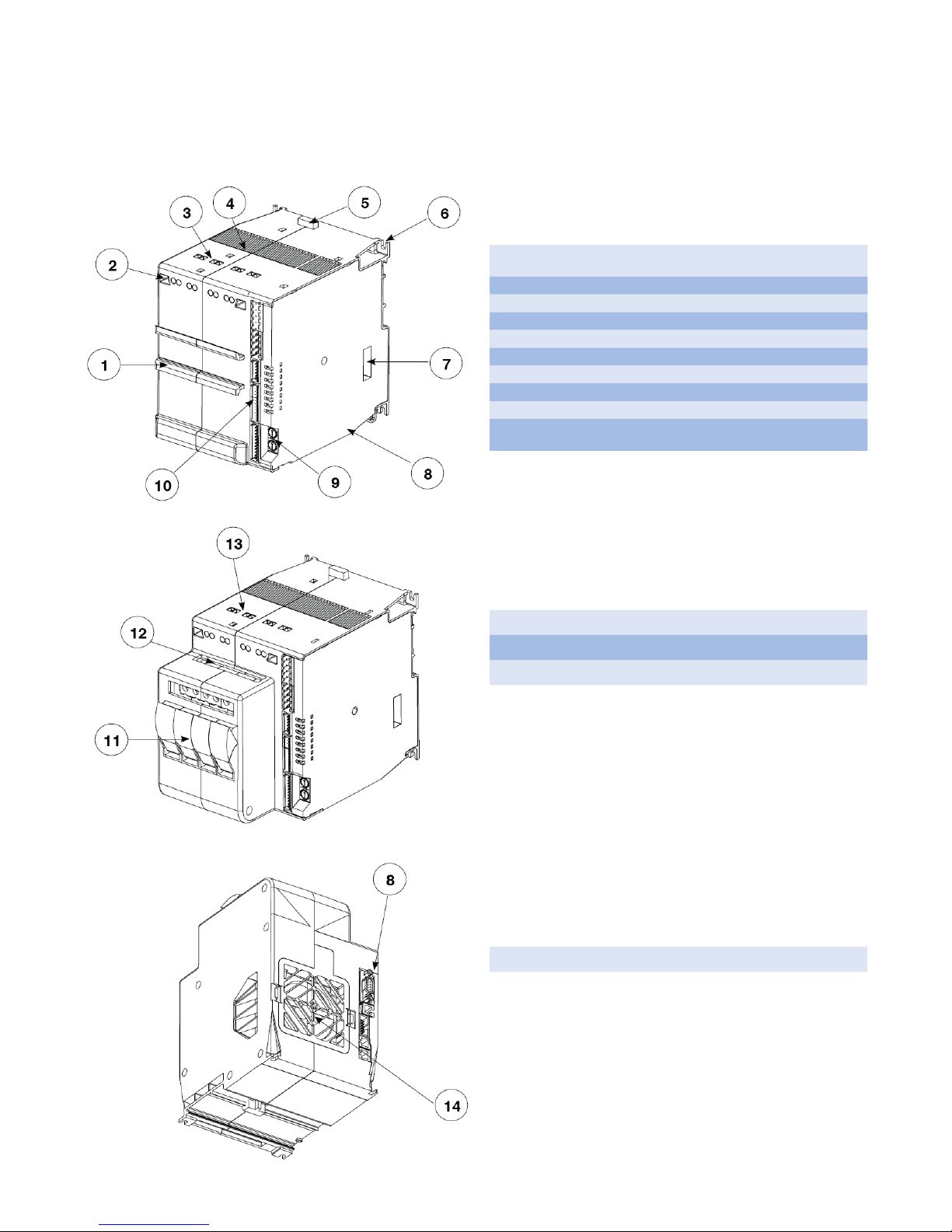
6. Controller Overview
6.1 Layout
Front DIN rail mount for the C4-OP programming module.
1.
This mount is only present on models without fuse holders.
2. Screwdriver access to power connection screws.
3. Power supply connection terminals
4. Heat sink ventilation screen: DO NOT OBSTRUCT
5. Spring clamp release for rear DIN rail.
6. Fastening slots for additional mounting security.
7. DIP switches for controller function / load configuration.
8. Communication ports (Port1, Port2).
9. Rotary switches for setting node address or number
Input signal & low voltage power supply terminals
10.
(J1, J2, J3, J4)
11. Fuse holders. (Only available on 30KW and 60KW models).
12. Terminals for fuse holder connection (F1, F2, F3, F4/N)
13. Terminals for load power connection (U1, U2, U3, U4)
14. Air intake / fan protection screen: DO NOT OBSTRUCT
7
Page 10
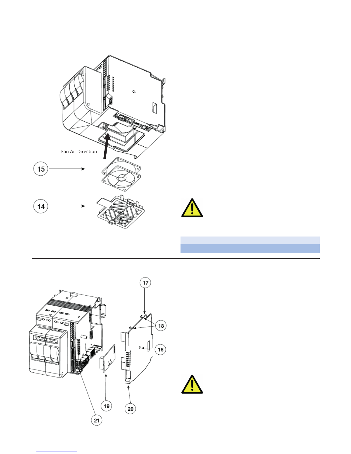
6.2 Cooling Fan
PERIODIC CLEANING
Every 6-12 months (depending on the dust level of
the installation) blow a compressed air jet downward
through the upper rectangular cooling grilles (on the
side opposite the fan). This will clean the internal heat
dissipater and the cooling fan.
IN CASE OF OVERHEAT ALARM
If periodic cleaning does not eliminate the problem, do
as follows:
a. Remove the fan support grille by detaching the two
support tabs
b. Disconnect the fan connector from the board
c. Check the condition of the fan
d. Clean or replace the fan
NOTE: Ensure that the air flow arrow on the fan is
pointing towards the heat sink e Insert the connector into the board
f. Insert the fan support grille until it attaches
g. Power up the device and check fan rotation when at
least one load is on
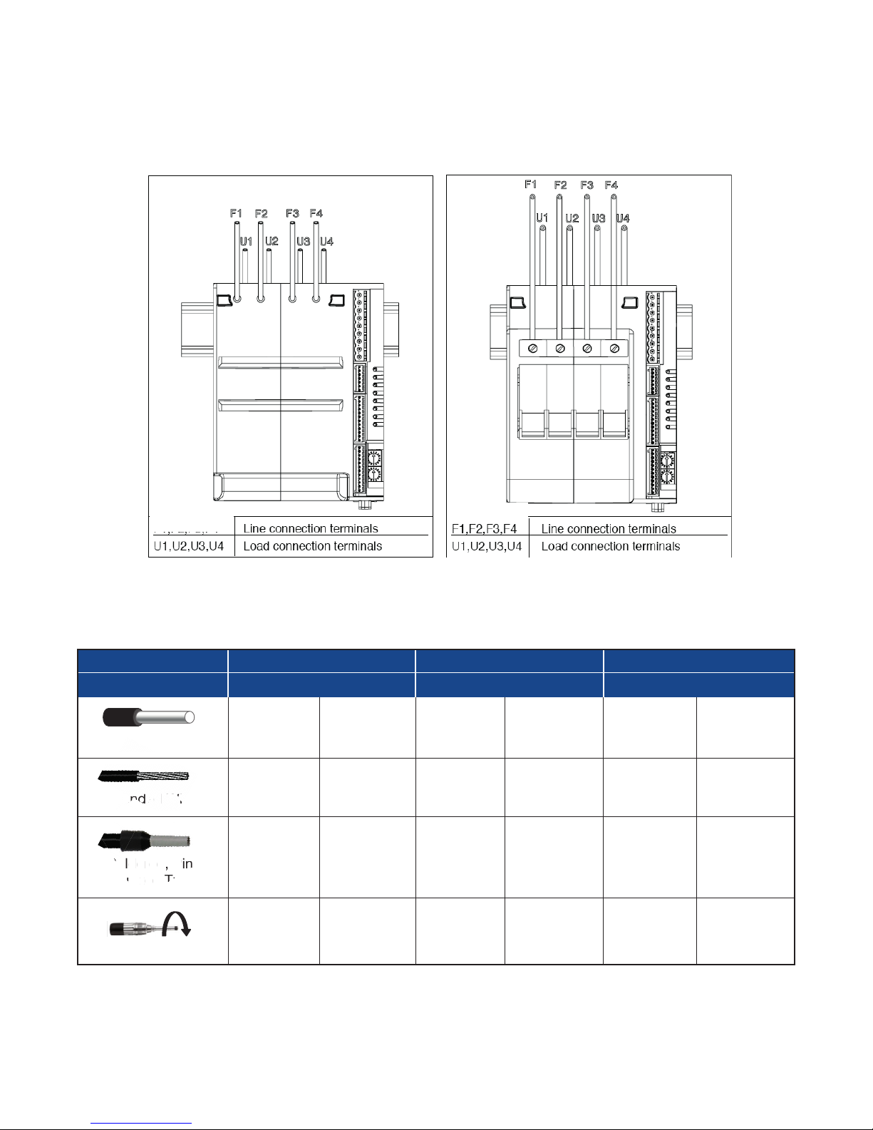
6.3 Inserting a New Field Bus Interface Card
Before and during the inspection/
maintenance, cut power to the fan
controller and verify that the system
is isolated for operator safety.
14 Support Grill
15 Fan
To insert a communication module, the Field Bus
Interface Board compartment must be accessed.
Follow these steps:
1. Remove the Fieldbus compartment cover screw
(16)
2. With a flat screwdriver, gently apply pressure at (18)
3. Remove compartment cover (17)
4. Insert Fieldbus card (19) into the proper connector
(21)
5. Remove applicable communication port tab (20) on
cover (17)
6. Carefully replace compartment cover (17)
7. Tighten compartment cover screw (16)
Before attempting board replacement,
ensure that power to the controller
has been cut and verify that the
system is isolated for operator safety.
8
Page 11
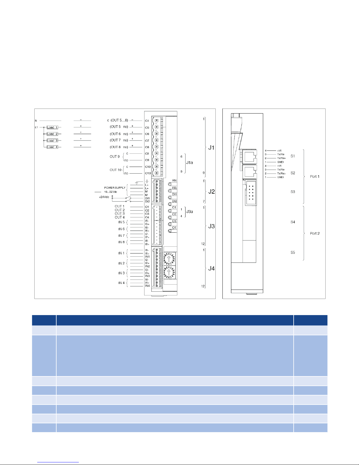
7. Connections and Indication
Model without fuse holder Model with fuse holder
So
li
Solid Wire
d
d
Solid Wire
Stranded Wire
d
d
Solid Wire
Stranded Wire
Soldered, Pin
Insulated Tube
Torque Force
d
d
7.1 Power Connections
F1,F2,F3,F4/
7.2 Power Wiring Considerations
Model 30kW 60kW 80kW
Max Current 16 Amps 30 Amps 40 Amps
Solid Wire
Stranded Wire
Soldered, Pin
Insulated Tube
0.2 - 6mm2 24 - 10 AWG 0.2 - 6mm2 24 - 10 AWG 0.5 - 16mm2 20 - 6 AWG
0.2 - 4mm2 24 - 10 AWG 0.2 - 4mm2 24 - 10 AWG 0.5 - 10mm2 20 - 7 AWG
0.25 - 4mm2 23 - 10 AWG 0.25 - 4mm2 23 - 10 AWG 0.5 - 10mm2 20 - 7 AWG
0.5 - 0.6Nm 0.5 - 0.6 Nm 1.2 - 1.5Nm
/N
4.4 - 5.3
In-lb
4.4 - 5.3
In-Lb
10.6 - 13.3
In-Lb
9
Page 12
7.3 Input & Output Connections
• Use adequately compensated cable for thermocouple inputs. Maintain polarity by avoiding junctions
on the cables.
• If using a grounded thermocouple, the connection
must be at a single point.
• For RTD inputs, use copper extension cables and
avoid junctions on the cables. Resistance must not
exceed 20 Ohm.
TRIAC Logic/Analog Relay
• For 2-wire RTDs, make the connection indicated instead of the third wire.
• Refer to the applicable Connectors Detail starting in
section 7.6
7.4 LED Logic
LED Description Color
RN RUN - Flashes during regular operation Green
ERROR (Fault Condition) - Illuminates when a fault is present
Lo = Process Variable value < Lo.S
ER
HI = Process Variable value > Hi.S
Sbr = Sensor interrupted or input values over maximum limits
Err = RTD third wire interrupted for Pt100 or input values below minimum
ER = (red) flashing: Alarm temperature OVER_HEAT (STATUS.STRUMENTO 4 bit 1)
DI1 State of digital input 1: DI1 Yellow
DI2 State of digital input 2: DI2 Yellow
O1 State of output 1: O1 Yellow
O2 State of output 2: O2 Yellow
O3 State of output 3: O3 Yellow
O4 State of output 4: O4 Yellow
Red
10
Page 13
7.5 Rotary Switches
0
Switch Drescription
0
1
F
2
E
3
D
4
C
5
B
A
9
8
0
1
F
E
D
C
B
A
9
8
X1
6
7
2
3
4
5
6
7
X1
Defines Address of Controller Module
Available address: 00...99
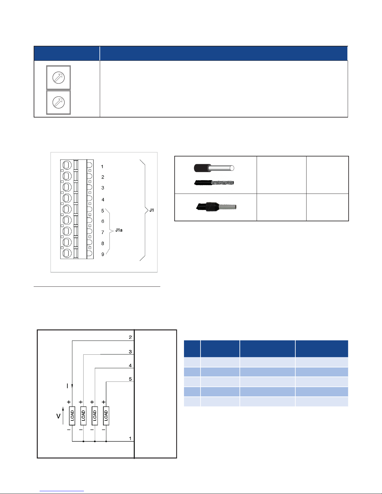
7.6 Connector Detail
7.6.1 Connector J1 / J1a (Note: If Auxiliary Outputs O5 - O8, are present, connector J1a becomes J1.)
0.2 - 2.5mm2 24-14 AWG
0.25 - 2.5mm2 23-14 AWG
Outputs 5 - 8: Logic or Analog Output Type
Logic outputs: 18 - 36Vdc, max 20mA
Analog outputs: Voltage (default): 0 - 10V, 2 - 10V, max 25mA or Current: 0 - 20mA, 4 - 20mA, max 500Ω
Wiring Schematic for Outputs 5 - 8, both Logic & Analog Outputs
O5
PIN Legend
Polarity
O6
O7
PIN Name Description
1 Com O5-O8 Outputs Common ( – )
(Logic or Analog)
2 O5 Output 5 ( + )
O8
3 O6 Output 6 ( + )
4 O7 Output 7 ( + )
5 O8 Output 8 ( + )
Com O5-O8
11
Page 14
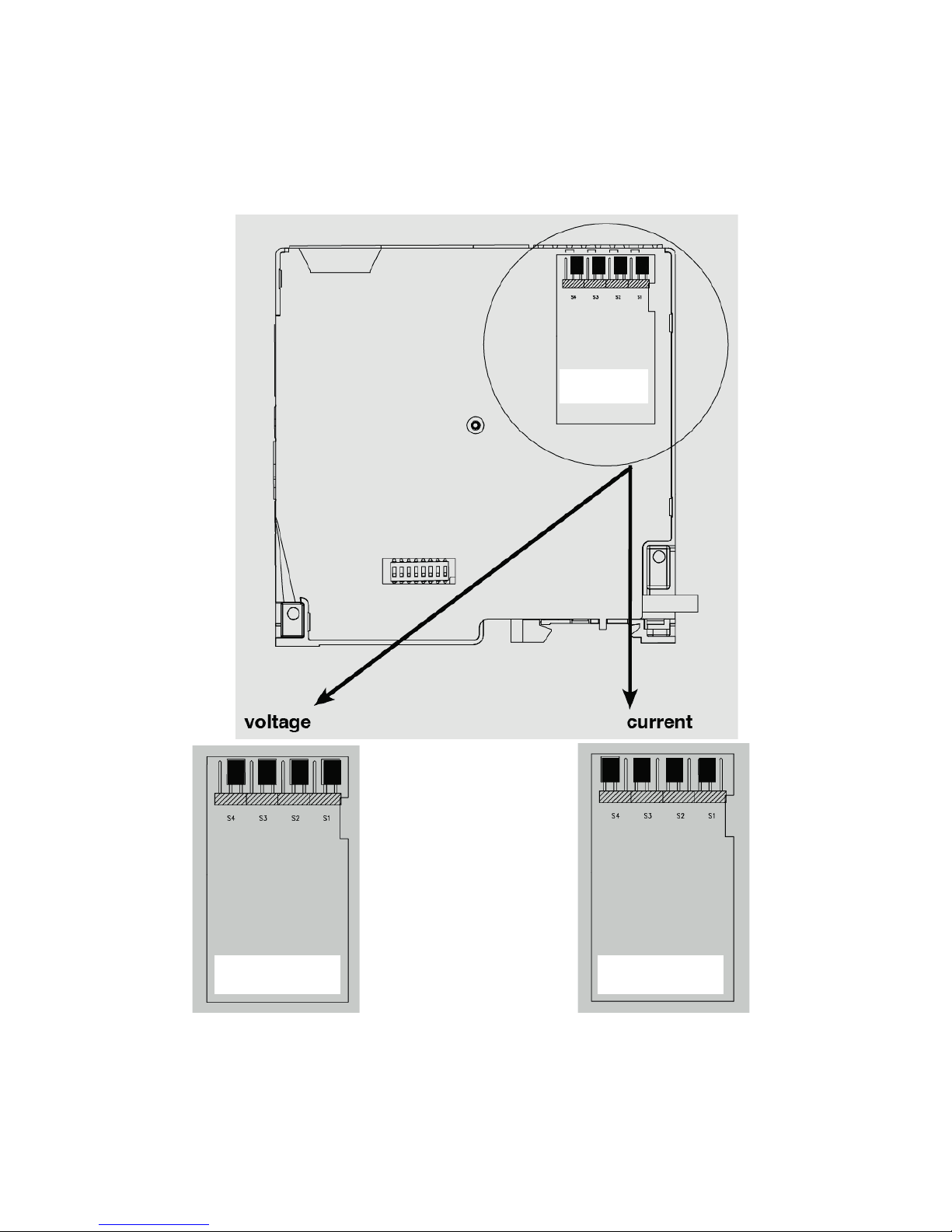
When the optional Auxiliary Output type “A” (Analog) is selected, one must choose whether the output is Voltagebased (default) or Current-based. This selection is carried out via proper jumper placement on the board as follows:
C4
Output Card
C4
Output Card
12
C4
Output Card
Page 15

Outputs 5 - 8: TRIAC Type
Com O5-O8
O5
O6
O7
O8
TRIAC outputs: Voltage: 24...230Vac, max 1A
Wiring Schematic for Outputs 5 - 8, TRIAC Outputs
Com O5-O8
O5
O6
O7
O8
PIN Legend
PIN Name Description
1
Com O5-O8 Outputs Common
2
3
4
O5 Output 5
O6 Output 6
O7 Output 7
5
Outputs 5 - 8: Relay Type
Outputs Out 5 - Out 8, Relay outputs: Ir = 3A max, NO (normally open)
V = 250V/30 Vdc cosw = 1; I = 12A max
Wiring Schematic for Outputs 5 - 8, Relay Outputs
Com O5-O8
O5
O6
O7
O8
PIN Name Description
1
Com O5-O8 Outputs Common
2
3
4
O8 Output 8
PIN Legend
O5 Output 5
O6 Output 6
O7 Output 7
13
5
O8 Output 8
Page 16

Outputs 9, 10: Relay Type
Outputs Out 9, Out 10, Relay outputs: 5A max
V = 250V/30Vdc cosw = 1; I = 5A max
Wiring Schematic for Outputs 9 & 10, Relay Outputs
PIN Name Description
1
2
3
4
7.6.2 Connector J2 (Power Supply, Digital Input 1 & Digital Input 2)
PIN Legend
Com O9 Output Common O9
O9 Output O9
Com O10 Output Common O10
O10 Output O10
Wiring Schematic for J2 - Power Supply, Digital Inputs
0.14 - 0.5mm2 28-20AWG
0.25 - 0.5mm2 23-20AWG
PIN Legend
PIN Name Description
1
2
3
4
5
6
L+
L+
M-
M-
DI1 Digital Input 1
Ground
Power Supply
18 - 32 Vdc
14
7
DI2 Digital Input 2
Page 17

7.6.3 Connector J3 (Auxiliary Inputs)
Wiring Schematic for J3 - Auxiliary Inputs
0.14 - 0.5mm2 28-20 AWG
0.25 - 0.5mm2 23-20 AWG
PIN Legend
PIN Name Description
1
2
3
4
5
6
7
8
9
10
11
12
- No Connection
- No Connection
- No Connection
- No Connection
15+ Auxiliary Input 5
I5- Auxiliary Input 5
I6+ Auxiliary Input 6
I6- Auxiliary Input 6
I7+ Auxiliary Input 7
17- Auxiliary Input 7
I8- Auxiliary Input 8
18+ Auxiliary Input 8
15
Page 18

7.6.4 Connector J4 (Inputs 1 - 4)
Inputs 1 - 4
0.14 - 0.5mm2 28-20 AWG
0.25 - 0.5mm2 23-20 AWG
PIN Legend
PIN
1
2
60mV/Tc
Linear Input
I1- I1- I1-
I1+ I1+
3
4
5
I2- I2- I2-
I2+ I2+
6
7
8
I3- II3- 13-
I3+ I3+
9
10
11
I4- I4- I4-
I4+ I4+
12
1V/20mA
Linear Input
IN1+ IN1
IN2+ IN2
IN3+ IN3
IN4+ IN4
Pt100
Input
16
Page 19

7.7 Dip-Switch Configuration
Dip
Switch
1
2
3
4
Dip Switch Legend
Function Description
Load Connection See Load Configuration Table Below.
No Function
5
6
7
8
Frequency ON: 60 Hz OFF: 50 Hz
Factory Default ON: Resets Controller to Factory Settings
Simulation ON: Simulation Mode
RS485
Communications
Load Configuration Table
Dip Switch
1 2 3
OFF
ON
OFF
ON
OFF
OFF OFF 4 independent zones (4 single-phase loads)
OFF OFF
Zone 1: 3-phase load, star (wye) connection, with
neutral
ON OFF Zone 1: 3-phase load, open delta connection
ON OFF
OFF ON
Zone 1 & 3: Two 3-phase loads, star (wye)
connection, without neutral
Zone 1 & 3: Two 3-phase loads, closed delta
connection
ON: When the device is the ONLY RS-485
device or when it is the LAST RS-485 device
Load Connection Type
ON
OFF
ON
OFF ON No Function
ON ON No Function
ON ON No Function
17
Page 20

7.8 Serial Communication Ports
Modbus RTU/RS485 Serial Interface
e C4-OP Section
7.8.1 Port1 (Standard Local Bus): Connectors S1, S2, S3
1 9 2 F
1 9 0 F
0 1
Connector S3 accepts the C4-OP local
interface terminal. See th
for more detail.
Connector S1/S2
RJ10 4-4 Pin Pin Name Description Note
Cable Type: Flat telephone cable for pin 4-4 conductor 28 AWG
1 GND1 (**) -
2 Tx/Rx+ Data reception/transmission (A+)
3 Tx/Rx- Data reception/transmission (B-)
4 +V Reserved -
(*) Enable #8 DIP Switch on
last device on Modbus RS485
line
(**) Connect the GND signal to
Modbus devices with a line
distance > 300 ft. (100 m)
18
Page 21

7.8.2 Port2 (Optional Fieldbus): Connectors S4, S5
le RJ10 Connector
le RJ10 Connector
A. Modbus RTU/RS485, Modbus RTU/RS485
Connector S4/S5
RJ10 4-4 Pin Pin Name Description Note
1 GND1 (**) -
2 Tx/Rx+ Data reception/transmission (A+)
(*) Enable Fieldbus DIP Switch
on last device on Modbus
RS485 line
(**) Connect the GND signal to
3 Tx/Rx- Data reception/transmission (B-)
Modbus devices with a line
distance > 300 ft (100 m)
4 +V Reserved -
Cable Type: Flat telephone cable for pin 4-4 conductor 28 AWG
S5 Fema
S4 Fema
End of line Modbus
Termination Dip Switch*
19
Page 22

B. Modbus RTU/RS485, Profibus DP Interface
le RJ10 Connector
Green LED
S5 Female DB9 Connector
Connector S4
RJ10 4-4 Pin Pin Name Description Note
1 GND1 (**) -
2 Rx/Tx+ Data reception/transmission (A+)
(**) Connect the GND signal to
Modbus devices with a line
distance > 300 ft. (100 m)
3 Rx/Tx- Data reception/transmission (B-)
4 +V Reserved -
Cable Type: Flat telephone cable for pin 4-4 conductor 28 AWG
S4 Fema
Yellow LED
Red LED
Connector S5
D-Sub 9 Pins Male Pin Name Description Note
1 Shield EMC Production
Connect the terminal resistances as shown in the figure.
2 M24V Output Voltage - 24V
3 RxD/TxD-P Data reception/transmission
4 n.c. n.c.
5 DGND Data Ground
6 VP Positive Power Supply +5V
7 P24V Output Voltage +24V
8 RxD/TxD-N Data Reception/Transmission
9 n.c. n.c.
Cable Type: Shielded 1 pair 22 AWG conforming to PROFIBUS.
20
Page 23

C. Modbus RTU/RS485, CANopen Interface
le RJ10 Connector
Green LED
Connector S4
RJ10 4-4 Pin Pin Name Description Note
1 GND1 (**) -
2 Rx/Tx+ Data reception/transmission (A+)
(**) Connect the GND signal
among Modbus devices with a
line distance > 300 ft. (100 m)
S5 Male DB9 Connector
S4 Fema
Red LED
3 Rx/Tx- Data reception/transmission (B-)
4 +V Reserved -
Cable Type: Flat telephone cable for pin 4-4 conductor 28 AWG
Connector S5
D-Sub 9 Pins
Female Pin Name Description Note
1 - Reserved Connect the terminal resis-
2 CAN_L CAN_L bus line (domination low)
3 CAN_GND CAN Ground
4 - Reserved
5 (CAN_SHLD) Optional CAN Shield
6 (GND) Optional Ground
7 CAN_H
CAN_H bus line (domination High)
8 - Reserved
Optional CAN external positive sup-
9 (CAN_V+)
ply (dedicated for supply of trans-
ceiver and optocouplers, if galvanic
isolation of the bus node applies)
tances as shown in the figure.
Cable Type: Shielded 2 pairs 22/24 AWG conforming to CANopen.
21
Page 24

D. Modbus RTU/RS485, DeviceNet Interface
Connector S4
RJ10 4-4 Pin Pin Name Description Note
1 GND1 (**) -
2 Rx/Tx+ Data reception/transmission (A+)
(**) Connect the GND signal to
Modbus devices with a line
distance > 300 ft. (100 m)
S5 Male Connector
S4 Female RJ10 Connector
Red LED
Green LED
3 Rx/Tx- Data reception/transmission (B-)
4 +V Reserved -
Cable Type: Flat telephone cable for pin 4-4 conductor 28 AWG
Connector S5
D-Sub 9 Pins Male Pin Name Description Note
Connect a 120Ω / 1/4W resis-
1 V- Negative Power Supply
tance between the “CAN_L”
and “CAN_H” signals at each
end of the DeviceNet network.
2 CAN_L Low Signal
3 SHIELD Shield
4 CAN_H High Signal
5 V+ Positive Power Supply
Cable Type: Shielded 1 pair 22 AWG conforming to PROFIBUS.
22
Page 25

E. Modbus RTU/RS485, Modbus TCP/Ethernet Interface
Green LED
S5 Female RJ45 Connector
Connector S4
RJ10 4-4 Pin Pin Name Description Note
1 GND1 (**) -
2 Rx/Tx+ Data reception/transmission (A+)
(**) Connect the GND signal
among Modbus devices with a
line distance > 300 ft. (100 m)
3 Rx/Tx- Data reception/transmission (B-)
4 +V Reserved -
Cable Type: Flat telephone cable for pin 4-4 conductor 28 AWG
S4 Female RJ10 Connector
Yellow LED
Connector S5
RJ45 Pin Name Description Note
1 TX+ Data + Transmission
2 TX- Data - Transmission
3 RX+ Data + Reception
4 n.c.
5 n.c.
6 RX- Data - Reception
7 n.c.
8 n.c.
Cable Type: Use standard category 6 cable according to TIA/EIA-568A.
23
Page 26

Modbus RTU/RS485, Ethernet IP Interface or Modbus RTU/RS485, EtherCAT Interface or
Modbus RTU/RS485, ProfiNET Interface
LED Logic - Ethernet IP Fieldbus Module
H1
LED GREEN Module State
H2
LED RED Module State
H7
LED RED Network State
H8
LED GREEN Network State
LED Bicolor GREEN (H1)
H4
RED (H2)
LED Bicolor GREEN (H8)
H6
RED (H7)
J1
Connector Port ETH0
J3
Connector Port ETH1
J2
Connector Serial Modbus
LED Logic - EtherCAT Fieldbus Module
H1
LED GREEN Link/Activity Port ETH0
H2
LED RED Run Run
H7
LED RED Run Run
H8
LED GREEN Link/Activity Port ETH1
LED Bicolor GREEN (H1)
H4
RED (H2)
LED Bicolor GREEN (H8)
H6
RED (H7)
J1
Connector Port ETH0 (IN)
J3
Connector Port ETH1 (OUT)
J2
Connector Serial Modbus
LED Logic - ProfiNet Fieldbus Module
H1
LED GREEN Link Port ETH0
H2
LED RED Signal Port ETH0
H7
LED RED Activity Port ETH1
H8
LED GREEN Link Port ETH1
LED Bicolor GREEN (H1)
H4
RED (H2)
LED Bicolor GREEN (H8)
H6
RED (H7)
J1
Connector Port ETH0
J3
Connector Port ETH1
J2
Connector Serial Modbus
Port ETH0
Port ETH1
Port ETH
Port ETH
Connector J2 RJ10 4-4 Pin
Pin Name Description Note
1 GND1 (**) -
+V
Data reception/
transmission
(A+)
Data reception/
transmission
(B-)
-
2 Tx/Rx+
3 Tx/Rx-
4
Reserved
Cable Type: Flat telephone cable for pin 4-4 conductor 28 AWG
Connector J1 and J3 RJ45
Pin Name Description Note
1 TX+ Data Transmission +
2 TX- Data Transmission -
3 RX+ Data Reception +
4 n.c.
5 n.c.
6 RX- Data Reception -
7 n.c.
8 n.c.
Cable Type: Use standard category 5 cable according to TIA/
EIA-568B
(**) It is
adviseable to
also connect
the GND signal between
Modbus
devices with a
line distance
> 300 ft.
(100 m)
24
Page 27
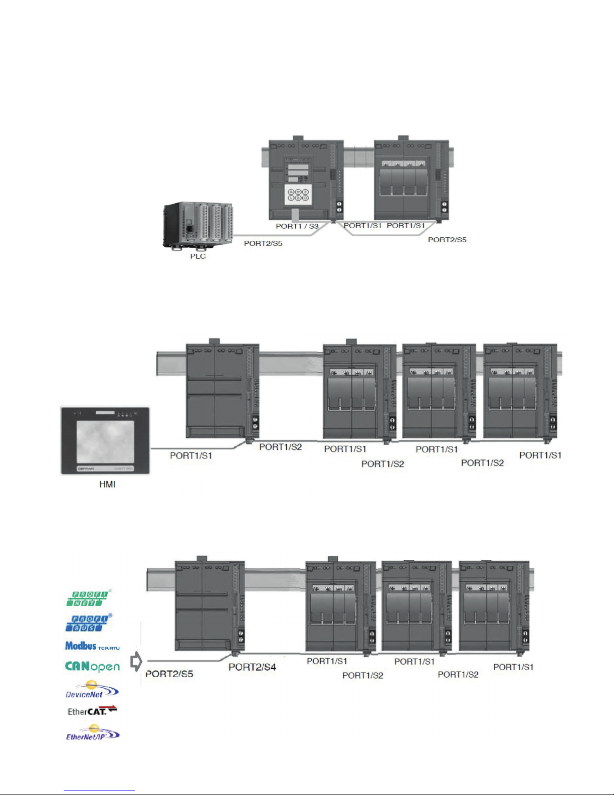
7.8.3 Connection Example: Communication Ports
A. Supervisory PC/PLC with multiple C4 Modules, with C4-OP.
May need to use Autobaud to synchronize communications.
B. HMI Connection via Modbus RTU (RS-485) to four C4 Modules
May need to use Autobaud function to synchronize communications.
C. SCADA System with fieldbus interface, Single Master Setup
May need to use AutoNode Sequence to set communications.
25
Page 28

D. C4 with Multiple Master Communications Ports
This configuration will allow two masters to simultaneously operate. This will allow the fieldbus to operate, while
allowing the 2nd port to be used for local information, verification of process, or for configuration tool C-PWR
software to be utilized.
Use Autonode to set communications.
C4 or C4-IR Fieldbus Network
Purple: Fieldbus Network wiring to Master Unit.
SW7 must be set to “off” on all units.
Blue: Fieldbus Network Slave Unit connection via RS-485.
Green: 2nd Master Communications Port for local master or configuration
using C-PWR Software
26
Page 29

E. C4 with a Single Master Communication Port
Use Autonode Sequence for configuration. See section 12.2
C4 or C4-IR Fieldbus Network
Purple: Fieldbus Network wiring to Master Unit.
SW7 must be set to “off” on all units.
Blue: Fieldbus Network Slave Unit connection via RS-485.
C-PWR Configuration Tool can be used via RS-485 ports only. Fieldbus connection must be broken to utilize configuration.
Single Master systems can be expanded to two master systems in field.
27
Page 30

F. Multiple Fieldbus Connections
C4 or C4-IR Fieldbus Network
Purple: Fieldbus Network wiring to Master Unit. SW7 must be set to “off” on
all units.
28
Page 31

8. Load Connection Example
3Ø Delta 3Ø Wye (Star)
The following wiring diagrams and electrical equations are provided as a reference for this manual. The three phase
equations shown can be applied to any balanced Delta or Wye (star) circuit. The terms used in the equations are
identified below:
Vl = Line Voltage Wt = Total Watts
Vp = Phase Voltage R1 = R2 = R3 = Element Resistance
Il = Line Current (Amps) Wc = Wattage per Circuit (Equal Circuits)
Ip = Phase Current (Amps) Rc = Circuit Resistance in Ohms Measured Phase to Phase
2
2
÷ R1)
2
The model C4 has specific dipswitch settings
for the various load configurations. Incorrectly setting with a mismatch load configuration
could result in unpredicted results. Please refer to section 7.7 or the Load Connection examples for these proper dipswitch settings.
2
2
÷ R
1
2
29
Page 32

Open Delta & Wye
3Ø Open Delta
3Ø Open Wye (Star)
of an element in a
Three phase heating circuits are most efficient when operated under balanced conditions. If it is necessary to operate an unbalanced load, the equations below can be used to calculate the circuit values for open three phase Delta
or Wye circuits. The terms used in the equations are identified below:
Note:
The loss of a phase or failure of an element in a
three (3) element Delta circuit will reduce the
wattage output by 33%
2
÷ R1)
Note:
The loss of a phase or failure
three (3) element Wye circuit will reduce the
wattage output by 50%. Heating elements are
basically in series on single phase power.
30
Page 33

8.1 4 Single-Phase Loads, 3-phase line with neutral
N
L1
L2
L3
The model C4 has specific dipswitch settings
for the various load configurations. Incorrectly
setting with a mismatched load configuration
could result in unpredicted results. Please refer to section 7.6 or the Load Connection examples for these proper dipswitch settings.
Dip Switch
OFF OFF OFF
Load Connection Type1 2 3
4 independent zones
(4 single phase loads)
Physical Wiring Diagram
L1
L2
L3
N
LOAD 1
F1 U1 F2 U2 F3 U3 F4/N U4
LOAD 2
LOAD 3
LOAD 4
8.2 4 Single-Phase Loads, 3-phase line without neutral
L1
L2
L3
F1
U1
LOAD 1
LOAD 2
F2
U2
LOAD 3
U3
F3
F4
U4
LOAD 4
LOAD 1
F1 U1 F2 U2 F3 U3 F4/N U4
LOAD 2
Dip Switch
Load Connection Type1 2 3
OFF OFF OFF
4 independent zones
(4 single phase loads)
LOAD 3
LOAD 4
31
Page 34

U1
F1
L1
L2
L3
8.3 Two 3-Phase Loads, Closed Delta
L1
L2
L3
U1
F1
L1
L2
L3
F2
U2
LOAD 1
LOAD 3
LOAD 2
LOAD 1
LOAD 2
LOAD 3
F1 U1 F2 U2 F3 U3 F4/N U4
LOAD 3A
LOAD 1A
LOAD 2A
Dip Switch
Load Connection Type1 2 3
OFF OFF ON
Zone 1 & 3: Two 3-phase loads,
closed delta connection
8.4 Two 3-phase loads, star (wye) without neutral
L1
L2
L3
F3
F4
F2
U3
U4
U2
LOAD 2A
LOAD 2
LOAD 1A
LOAD 3A
LOAD 1
LOAD 3
LOAD 3
LOAD 1
F1 U1 F2 U2 F3 U3 F4/N U4
LOAD 2
Dip Switch
Load Connection Type1 2 3
Zone 1 & 3: Two 3-phase loads,
ON ON OFF
star (wye) connection, without
neutral
LOAD 3A
LOAD 2A
LOAD 1A
F3
F4
U3
U4
LOAD 1A
LOAD 2A
LOAD 3A
32
Page 35

8.5 One 3-phase load active, One 3-phase load inactive, Wye without neutral
L3
L1
L2
L3
Dip Switch
Load Connection Type1 2 3
ON OFF ON
Zone 1: 3-phase load, star (wye)
connection, with neutral
8.6 One 3-phase load, inside delta
LOAD 1
U1 F1 U2 F2 U3 F3 U4 F4
LOAD 2
LOAD 3
Dip Switch
Load Connection Type1 2 3
OFF ON OFF
Zone 1: 3-phase load, open delta
connection
L1
L2
F1
F2
U1
U2
LOAD 2
LOAD 1
LOAD 3
F3 U3
33
Page 36

9. Inductive and Transformer Coupled Load Guidelines
The model C4 should not be used for Inductive or Transformer Coupled Loads. The model C4-IR is capable of being used for these types of loads. Please refer to the C4-IR Hardware Manual for more details.
10. Communications Port (Modbus RTU/RS485)
A network typically has a Master that “manages” communication by means of “commands,” and Slaves that
carry out these commands.
Parameter Default Range
ID 1 1...99
BaudRate 19.2kbits/s 1,2...57.6k bits/s
Parity None Parity/Odd Parity/None
StopBits 1 -
DataBits 8 -
C4 modules are considered Slaves to the network master, which is usually a supervision terminal or a PLC.
They are positively identified by means of a node address (ID) set on rotary switches (tens + units).
A maximum of 99 C4 modules can be installed in a serial network, with node address selectable from “01”
to “99” in standard mode in which each C4 identifies
4 zones with sequential node address starting with the
code set on the rotary switches.
C4 modules have a ModBus serial (Serial 1) and, optionally (see order code) a Fieldbus serial (Serial 2) with
one of the following protocols: Modbus RTU, Profibus
DP, CAN open, DeviceNet, and Ethernet Modbus TCP.
The ModBus RTU port 1 has the following factory settings (default):
Position of
Rotary
Switches
Procedures
AutoBaud 0 0
AutoNode* A 0
The following procedures are indispensable for the
Modbus protocol. For the other protocols, see the specific manuals. The use of rotary switches (A...F) letters
is for particular procedures described in the following
paragraphs.
DescriptionTens Units
It enables to set the
correct BaudRate Value
It enables to transfer
the correct node (ID)
address (tens)
34
Page 37
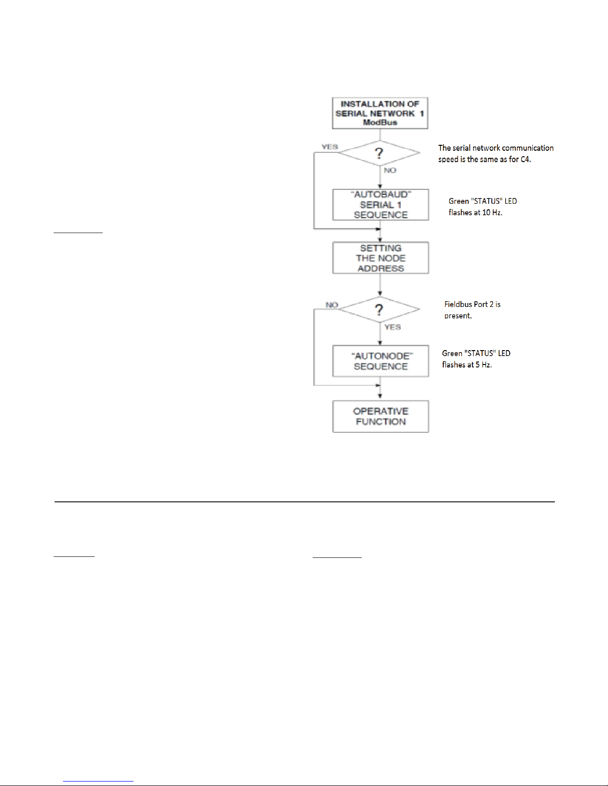
Section 11 Autobaud Function
11.1 Autobaud Port 1 Sequence
11.2 Autonode Sequence for Fieldbus Use Function
Adapt the serial communication speed and parity of
the C4 modules to the connected supervision terminal
or PLC. If a fieldbus card (port 2) is used then port 1
settings must remain at factory settings.
Green LED L1 “STATUS” mentioned in the procedure
can vary its behavior based on parameter Ld.1, which
is set to a default value of 16.
Procedure
1. Connect the serial cables for all modules on the network to serial 1 and to the supervision terminal.
2. Set the rotary switch on the C4 modules to be installed, or on all modules present in case of first installation, to position “0+0”.
3. Check that the green “STATUS” LEDs flash at high
frequency (10Hz).
4. The supervision terminal must transmit a series of
generic “MODBUS” read messages to the network.
5. The procedure is over when all of the green L1
“STATUS” LEDs on the C4 modules flash at a normal frequency (2Hz) (if parameter 197 Ld. 1 = 16 as
default).
The new speed parameter is saved permanently in each
C4; therefore, the “AUTOBAUD SERIAL 1” sequence
does not have to be run at subsequent power-ups.
When the rotary switch is turned, the green “STATUS”
LED stays on steadily for about 6 seconds, after which
it resumes.
11.2 Autonode Sequence for Fieldbus Use
Function
Autonode should be run for all field bus installations.
The L1 “STATUS” green LED mentioned in the procedure can vary its behavior according to the Ld.1 parameter which is 16 as default.
Procedure
1. Connect the serial cables to all the module in the
serial 1 network, disconnect supervision or C4-OP
terminals.
2. Turn the rotary switches from the set node address
to the position “A + 0”.
3. Check that the “STATUS” green LED is blinking at
an average frequency (5Hz) for 10 seconds and then
that it returns to normal blinking (2Hz).
4. Turn the rotary switches in the position of the node
address.
35
Page 38

12. Specifications
INPUTS
IN1 Analog Process Inputs
Function Acquisition of process variable
Max. Error 0,2% f.s. ± 1 scale point at room temperature of 25°C
Thermal drift < 100 ppm/˚C f.s.
Sampling time 120 ms
J,K,R,S,T
Thermocouple Tc (ITS90)
Resistance thermometer RTD (ITS90)
Voltage
Current
IN5, ... ,1N8 Auxiliary Analog Inputs (option)
Function Acquisition of variables
Accuracy 1% f.s. + 1 scale point at room temperature of 25°C
Sampling time 480 ms
Thermocouple Tc (ITS90)
Voltage linear: 0, ... ,60mV, Ri>1 Mohm
IN9, ... IN12 Inputs Internal Current Transformers CT
Function
Accuracy 1% f.s. ± 1 scale point at room temperature of 25°C
Sampling time 60 ms
DI1 ... DI2 Digital Inputs
Function Configurable (default: disabled)
Type PNP, 24 VDC, 8mA 3500V isolation
OUT1, ... , OUT4 Heat Control Outputs Connected Directly to Solid State Power Units
Function
OUT5, ... , OUT8 Cool Control Outputs (option)
Function Configurable (default: cool control)
Relay Type 3A NO Contact, 250V/30Vdc COSw =1
Continuous Type
Logic Type 24 Vdc, > 18V a 20mA
Triac Type
(IEC 584-1 ,CEI EN 60584-1, 60584-2)
Fault cold junction comp 0,1˚/˚C
Pt1 00 (DIN 43760)
MMax line resistance 20ohm
linear: 0, . .. ,60mV, Ri>1 Mohm
0, ... , 1V, Ri> 1 Mohm
a 32 segment custom linearization can be inserted
Linear: 0/4 ... 20mA, Ri =50ohm
a 32 segment custom linearization can be inserted
J,K,R,S,T
(IEC 584-1, CEI EN 60584-1, 60584-2)
Fault cold junction comp 0,1˚/˚C
Read internal CTs; (The acquisition of current values is valid for voltages in a range of 90 ... 530Vac)
OUTPUTS
Configurable (default: heat control)
Control state is displayed by LED (01 , . .. ,02)
0/2 .. . 10V, (default) max 25mA
protection against short circuit
0/4 . .. 20mA, max. load 500ohm
1500V isolation
230V/max 4A AC51
(1 A for every channel)
36
Page 39

OUT9, ... , OUT10 Alarms
Function Configurable (default: alarms)
Relay Type 5A NO Contact, 250V/30Vdc COSw =1
COMMUNICATIONS
PORT 1 (present)
Function Local serial communication
Protocol ModBus RTU
Baudrate Settable to 1,2...57.6kbits/s, (default 19.2 kbit/s)
Address Node Settable by rotary switch
Type
RS485
1500V isolation, double connector RJ10 telephone type 4-4
PORT 2 (Fieldbus Option)
Function Fieldbus serial communication
ModBus RTU, type RS485, baudrate 1,2...57.6 kbit/s
CANOpen 10K….1Mbit/s
Protocol
DeviceNet 125K...0.5Mbit/s
Profibus DP 9.6K...12 Mbit/s
Ethernet Modbus TCP, Ethernet IP 10/100Mbps
EtherCAT, ProfiNET 100Mbps
POWER (SOLID STATE POWER UNITS, 4 UNITS)
Rated Voltage 480VAC
Work Voltage Range 24...530 Vac
Non- repetitive Voltage 1200Vp
Zero Switching Voltage <20V
Rated Frequency 50/60Hz self-setting
Rated Current AC51 30KW 60KW 80KW
4 x 16A 4 x 30A 4 x 40A
Non- Repetitive Overcurrent (t=20 msec)
2
t For Fusion (t=1...10 msec) 645A’s 1010A’s 6600A’s
I
400A 600A 1150A
Critical Dv/dt with output Deactivated 1000V/usec
Rated Isolation Voltage 4000V
Safety
Selection ˚C/˚F Configurable
Linear scale range -1999 ... 9999
Control Actions
pb-dt-it 0,0 ... 999,9 % - 0,00 ... 99,99 min - 0,00 ... 99,99 min
Action - Control Outputs heat/cool - ON/OFF, PWM, GTT
Heat/Cool Max. Power Limitation 0,0 ... 100,0%
Cycle Time – Softstart
Fault Power Setting -100,0 ... 100,0%
Shut-Down Function Maintains sampling of process variable PV; when active, disables control
FUNCTIONS
Detects short circuit or open probe circuit, probe, power supply failure, LBA
alarm, HB alarm
4 control loops:
Double action (heat/cool) PID, on-off
Self-tuning at power-up, Continuous Autotuning, One-shot Autotuning
0 ... 200 s - 0,0 ... 500,0 min
Softstart at phase slicing
37
Page 40

Configurable Alarms
Alarm is assigned to an output, configurable as: maximum, minimum, symmetrical, absolute/deviation, LBA, HB
Alarm Masking Exclusion at power-up, latch, reset by digital input
SCR in short circuit (presence of current with control OFF)
Diagnostics
SCR open (presence of voltage on SCR with control ON)
Load interrupted or no voltage (no current, no voltage on SCR with control ON)
Connection and Load Types
Selection with Dip-Switches
4 loads single-phase,
2 loads 3-phase, star without neutral controlled on two phases
2 loads 3-phase, closed triangle controlled on two phases
1 load 3-phase, star with neutral controlled on one phase
1 load 3-phase, open triangle controlled on one phase
(with 3-phase load, 4 CTs are needed if diagnostics is required)
GENERAL DATA
Power Supply 24VDC +/-25%, max 8VA
Eight LEDS:
RN CPU in run state
Indicators
ER Fault Signal
DI1, DI2 state of digital inputs
O1,...O4 state of outputs
Protection IP20
Work/Storage Temperature 0 - 50˚C (see dissipation curves) / -20˚C...70˚C
Relative Humidity 20 - 85% RH non-condensing
Ambient Work Conditions Indoor use, altitude up to 2000m
Installation DIN RAIL EN50022 or panel using screws
Installation category II, Pollution level 2, double isolation
Installation Instructions
Max surrounding air temperature 50˚C (for UL)
Open type equipment
Weight(s)
Models 30KW, 60KW, 80KW 1200g
Models 30KW, 60KW, with fuse holder 1600g
38
Page 41

C4
164
(4x16A)
304
(4x30A)
404
(4x40A)
VOLTAGE/CURRENT CONSIDERATIONS
Current (Amp) Voltage (VAC) Power (kW)
Max. Per Channel Range Nominal Working Per Channel Controller Total
120 1.9 7.7
208 3.3 13.3
16
30
40
24 - 530 480
240 3.8 15.4
277 4.4 17.7
400 6.4 25.6
480 7.7 30.7
120 3.6 14.4
208 6.2 25.0
240 7.2 28.8
277 8.3 33.2
400 12.0 48.0
480 14.4 57.6
120 4.8 19.2
208 8.3 33.3
240 9.6 38.4
277 11.1 44.3
400 16.0 64.0
480 19.2 76.8
DISSIPATING CURVES
39
Page 42

13. Ordering Information
Model C4 SCR Power Controller
C4
Code Current Per Loop @ 40˚C (104˚F) Ambient, continuous service (110 Vac to 480 Vac) (See note 3)
164
16 Amps/Loop
304
30 Amps/Loop
404
40 Amps/Loop
Code Auxiliary Outputs
0
None
R
Relay
D
Logic
A
Analog
T
Triac
Code Auxiliary Inputs
1
One Current Transformer
2
4 Current Transformers
3
1 Current Transformer + 4 Linear Inputs
4
4 Current Transformers + 4 Linear Inputs (See Note 1)
Code Fusing
0
None
F
Fuse holder & Extra rapid fuses (See Note 2)
Code Second Fieldbus Option
00
None
MR
Modbus RTU (RS485)
ET
Modbus TCP/Ethernet
ER
Ethernet IP, Real Time
PB
PN
EC
CN
DN
EM
Profibus DP
ProfiNET
EtherCAT
CANopen
DeviceNet
Euromap 66
1
1
1
C4- 304 D 4 - F 00 Typical Model Number
1
Not available with EC, PN & ER Fieldbus Codes.
2
Not available with 404 Current Code
3
Refer to the C4X for higher amperages
40
Page 43

14. Configuration and Programming
14.1 C-PWR Configuration Software Program
See C-PWR Configuration Software Program instruction manual for proper program installation.
14.2 C4/C4X/C4-IR Programming Manual
See C4/C4X/C4-IR Programming Manual for complete controller set-up of communications, inputs, outputs,
alarms and control modes.
15. Accessories
15.1 Fuses and Fuse Holders
2
T Extra Rapid Fuses Fuse Holder
I
Fuse Rating,
C4 Model
Amps I
C4-164 16A 645A
2
T
2
C4-304 30A 1010A
15.2 Fieldbus Cards
Fieldbus Type Part No.
Modbus RTU 0149-50103 C4-MOD F032357 Card for Modbus RTU protocol (serial 2)
Profibus DP 0149-50104 C4-PROFI F032358 Card for Profibus DP protocol (serial 2)
CANopen 0149-50105 C4-CAN F032359 Card for CANopen protocol (serial 2)
DeviceNet 0149-50106 C4-DNET F032360 Card for DeviceNet protocol (serial 2)
Modbus TCP/IP 0149-50107 C4-ETH F033532 Card for Ethernet Modbus TCP protocol (serial 2)
EtherCat 0149-50108 C4-ETH2 F049411 Card for EtherCat protocol (serial 2)
Profinet 0149-50109 C4-ETH4 F054949 Card for Profinet protocol (serial 2)
Ethernet IP (Real-Time) 0149-50110 C4-ETH5 F058234 Card for Real Time Ethernet/IP protocol
Power
Dissipation Fuse Size
Manufacturer’s
Model Code Part No. Part No.
Fuse Holder
Rating (UL)
s 3.5W 10x38 FUS-016 0024-07824 0024-12124 30A@600V
2
s 4.8W 10x38 FUS-030 0024-07825 0024-12124 30A@600V
Model No.
(Fieldbus
Card)
Manufacturer’s
Model Code Description
Additional Spare Parts
Part No.
Manufacturer’s
Model Code Description
0149-50099 F032861 Connection cable for serial Modbus (RJ10) 0.3M
0149-50100 F032862 Connection cable for serial Modbus (RJ10) 1M
0149-50101 F032863 Connection cable for serial Modbus (RJ10) 2M
0149-50102 F032864 Connection cable for serial Modbus (RJ10) 5M
0149-50111 VEN-61 Fan (flow 39m3/h) for C4-164
0149-50112 VEN-62 Fan (flow 56m3/h) for C4-304 and C4-404
0149-50113 GRI-4 Grill fan for C4
0149-50114 FLT-4 Filter for fan
0149-50115 COUT4-9 9-Terminal Connector (J1) For C4 Controller
0149-50116 COUT4-4 4-Terminal Connector (J1a) For C4 Controller
0149-50117 CSIG4-7 7-Terminal Connector (J2) For C4 Controller
0149-50118 CSIG4-12 12-Terminal Connector (J4) For C4 Controller
0149-50119 CSIG4-4 4-Terminal Connector (J3a) For C4 Controller
41
Page 44

15.3 Configuration Software and Cabling
Configuration kit for C4 product line by means of PC with USB (Windows environment). Software is compatible
with all C4 models. Download free at www.Chromalox.com
- Allows you to read and write all of the parameters of a single C4 device
- Easy and rapid configuration
- Saving and management of parameter recipes
- On-line trend and saving of historical data
Description Part No.
Communication Cable, USB to TTL 309171
Communication Cable, USB to RS485 309180
15.4 C4-OP
Operator terminal for in-field configuration of the entire C4 product line.
Two types of terminals: - for installation on DIN guide
- for panel installation
See C4-OP Hardware Manual for more details.
Please refer to the Chromalox limited warranty applicable to this product at
http://www.chromalox.com/customer-service/policies/termsofsale.aspx.
© 2018 Chromalox, Inc.
Limited Warranty:
Chromalox, Inc.
1347 Heil Quaker Boulevard
Lavergne, TN 37086
(615) 793-3900
www.chromalox.com
42
 Loading...