

Page 1

C4 4-Channel SCR Power Controller with
Independent PID Control Quick Start
Manual 0037-75569 (PK541)
This manual is intended to be a quick reference guide for basic installation requirements and an overview of the connections, wiring considerations, and general specifications for the C4 4-Channel SCR Power Controller with Independent PID control.
For complete installation and operation, refer to the PK544 C4 Hardware Instruction
Manual. For complete configuration and programming refer to the PK548 C4 Configuration and Programming Manual. The most current revisions may be found on
the Chromalox website: www.chromalox.com
1. IMPORTANT SAFEGUARDS
ELECTRIC SHOCK HAZARD: Read and understand all instructions before
installing, servicing or operating this controller. Failure to do so could
result in equipment or property damage as well as personal injury and
even death.
HIGH VOLTAGE is used in the operation of this equipment. DEATH ON
CONTACT may result if personnel fail to observe safety precautions.
Learn the areas containing high-voltage connections when installing or
operating this equipment.
Be careful not to contact high-voltage connections when installing or
operating this equipment. Before working inside the equipment, turn
power off and ground all points of high voltage potential before touching.
ELECTRIC SHOCK HAZARD. Any installation involving control equipment must be performed by a qualified person and must be effectively
grounded in accordance with the National Electrical Code to eliminate
shock hazard.
The Owner/Installer must provide all necessary safety and protection
devices and follow all current electrical wiring standards and regulations. Failure to do so may compromise the integrity of the controller
and/or cause product failure resulting in a safety risk to operational
service and personnel.
This controller utilizes a heat sink which is designed to cool the unit
during operation. Under no circumstance should air flow around the
controller be compromised in any way. Failure to do so may result in the
overheating of the controller, product failure, product temperatures and
even fire.
During continuous operation, the heat sink can reach a very high
temperatures, and keeps a high temperature even after the unit is
turned off due to its high thermal inertia.
2. OVERVIEW & LAYOUT
Use the extra rapid fuses as indicated in the C4 Hardware Instruction Manual PKXXX,
according to the wiring schematic examples and controller rating. Additionally, the
applications with solid state units require safety automatic switch to disengage the
load power line during certain alarm events.
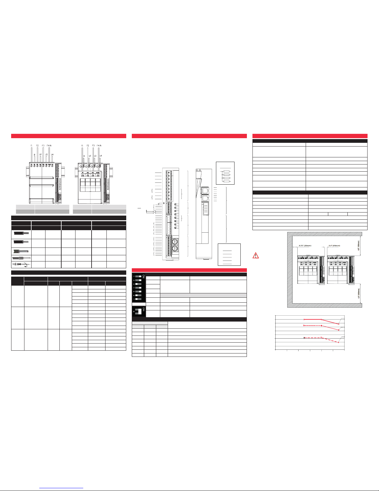
Installation Wiring Note:
Item Description
1. Front DIN Rail Mount For C4-OP
2. Power terminal: screws
3. Power terminal
4. Ventilation screen (DO NOT Obstruct)
5. Spring clamp release for rear DIN rail
6. Screw holes for additional mounting
7. DIP switch for configuration
8. Communication Port
9. Rotary switch for addressing
10. Connectors J1, J2, J3, J4
11.
Fuse holder
(only for 30KW and 60KW models)
12. Fuse holder terminals (F1, F2, F3, F4/N)
13. Power terminals (U1, U2, U3, U4)
14. Ventilation screen (DO NOT Obstruct)
1
2
3
4
5
6
7
8
9
10
8
14
11
12
13
Before and during the inspection/ maintenance cut power to the fan
controller and verify that the system is isolated for operator safety.
COOLING FAN CARE
Periodic Cleaning
Every 6-12 months (depending on the
dust level of the installation) blow a compressed air jet downward through the upper rectangular cooling grilles (on the side
opposite the fan). This will clean the internal heat dissipater and the cooling fan.
In Case of Overheat Alarm
If periodic cleaning does not eliminate the
problem, do as follows:
a. Remove the fan support grille by
detaching the two support tabs
b. Disconnect fan connector from board
c. Check the condition of the fan
d. Clean or replace the fan (*)
e. Insert the connector into the board
f. Insert fan support grille until it attaches
g. Power up the device and check fan
rotation when at least one load is on
15
14
Direction
of air flow
14. Support Grill
15. Fan
Before attempting board replacement, ensure that power to the controller
has been cut and verify that the system is isolated for operator safety.
INSERTING A NEW FIELD BUS INTERFACE CARD
To insert a communication module, the Field Bus Interface Board compartment
must be accessed. Follow these steps:
1. Remove the Fieldbus compartment cover screw 16
2. With a flat screwdriver, gently apply pressure at 18
3. Remove compartment cover 17
4. Insert Fieldbus card 19 into the proper connector 21
5. Remove applicable communication port tab 20 on cover 17
6.
Carefully replace compartment cover 17
7. Tighten compartment cover screw 16
16
17
18
19
20
21
PK541
0037-75569
January 2018
© 2018 Chromalox, Inc.
Page 2
3. WIRING
Power Wiring Considerations
Model without fuse holder Model with fuse holder
F1,F2,F3,F4/N Line Connection Terminals
U1,U2,U3,U4 Load Connection Terminals
F1,F2,F3,F4/N Line Connection Terminals
U1,U2,U3,U4 Load Connection Terminals
Model 30 kW 60 kW 80 kW
Item 16A 30A 40A
rigid
0.2-6mm2 24-10 AWG 0.2-6mm2 24-10 AWG 0.5-16mm2 20-6 AWG
rigid
flexible
0.2-4mm2 24-10 AWG 0.2-4mm2 24-10 AWG 0.5-10mm2 20-7 AWG
rigid
flexible
0.25-4mm2 23-10 AWG 0.25-4mm2 23-10 AWG 0.5-10mm2 20-7 AWG
rigid
flexible
0.25-4mm2 23-10 AWG 0.25-4mm2 23-10 AWG 0.5-10mm2 20-7 AWG
rigid
flexible
0.5-0.6 Nm 4.4-5.3 In-Lb 0.5-0.6 Nm 4.4-5.3 In-Lb 1.2-1.5 Nm 10.6-13.3 In-Lb
Voltage/Current Considerations
C4
Current (Amp) Voltage (Vac) Power (kW)
Max Per Channel Range Nominal Working Per Channel Controller Total
164
(4x16A)
16 24-530 480
120 1.9 7.7
208 3.3 13.3
240 3.8 15.4
277 4.4 17.7
400 6.4 25.6
480 7.7 30.7
304
(4x30A)
30 24-530 480
120 3.6 14.4
208 6.2 25.0
240 7.2 28.8
277 8.3 33.2
400 12.0 48.0
480 14.4 57.6
404
(4x40A)
40 24-530 480
120 4.8 19.2
208 8.3 33.3
240 9.6 38.4
277 11.1 44.3
400 16.0 64.0
480 19.2 76.8
4. OPTIONS, INPUTS AND OUTPUTS CONNECTIONS
• Use adequately compensated cable for thermocouple inputs. Maintain polarity
by avoiding junctions on the cables
• If using a grounded thermocouple, the connection must be at a single point
• For RTD inputs, use copper extension cables and avoid junctions on the cables.
Resistance must not exceed 20 Ohm
• For 2-wire RTD’s, make the connection indicated instead of the third wire
• Refer to the applicable Connectors Detail
N
L1
Load 1
Load 2
Load 3
Load 4
+
+
+
+
_
c (OUT 5,...8)
(OUT 5 no)
OUT 9
(OUT 6 no)
(OUT 7 no)
(OUT 8 no)
OUT 10
c
c
no
no
+
+
+
+
_
POWER SUPPLY
18...32Vdc
+24Vdc
OUT 1
OUT 2
OUT 3
OUT 4
IN 5
IN 6
IN 7
IN 8
IN 1
IN 2
IN 3
IN 4
C1
O5
O6
O7
O8
C9
O9
C10
O10
O1
O2
O3
O4
O2
O3
O4
J3a
RN
J1a
ER
DI2
DI1
J1
J2
J3
J4
1
9
1
7
1
12
1
12
DI2
DI1
M
M
L+
L+
O1
I5I5+
I6I6+
I7I7+
I8I8+
I1I1+
IN1
I2I2+
IN2
I3I3+
IN3
I4I4+
IN4
Triac
Port 1
Port 2
S1
S2
S3
S4
S5
4
3
2
1
4
3
2
1
+VI
Tx/RxTx/Rx+
GNDI
+VI
Tx/RxTx/Rx+
GNDI
6
9
1
4
Relay
Logic/continuous
5. DIP SWITCH CONFIGURATION
Dip Switch Legend
Dip Switch Function Description
1
Load Connection
See Load Configuration
Table Below
2
3
4 No Function
5 Frequency ON: 60 Hz OFF: 50 Hz
6 Factory Default ON: Resets Controller to Factory Settings
7 Simulation ON: Simulation Mode
8 RS-485 Communications
ON: When the device is the ONLY RS485 Device
or when it is the LAST RS485 Device
Load Configuration Table
Dip Switch
Load Connection Type
1 2 3
OFF OFF OFF 4 Independent zones (4 single-phase loads)
ON OFF OFF Zone 1: 3-phase load, star (wye) connection, with neutral
OFF ON OFF Zone 1: 3-phase load, open delta connection
ON ON OFF Zone 1 & 3: Two 3-phase loads, star (wye) connection, without neutral
OFF OFF ON Zone 1 & 3: Two 3-phase loads, closed delta connection
ON OFF ON No Function
OFF ON ON No Function
ON ON ON No Function
6. GENERAL DATA
General Data
Power Supply
24 VDC +/-25%, max 8VA
Indicators
Eight LEDS:
RN CPU in run state , ER Fault Signal
DI1, DI2 state of digital inputs
O1,...O4 state of outputs
Protection
IP20
Work/Storage Temperature
0 - 50˚C (see dissipation curves) / -20˚C...70˚C
Relative Humidity
20 - 85% RH non-condensing
Ambient Work Conditions
Indoor use, altitude up to 2000m
Installation
DIN RAIL EN50022 or panel using screws
Installation Instructions
Installation category II, Pollution level 2, double isolation
Max surrounding air temp. 50˚C (for UL) Open type equipment
Weight
Models 30kW, 60kW, 80kW
1200g
Models 30kW, 60kW, w/fuse holder
1600g
Current [A]
Ambient Temperature [°C]
DERATING
45
40
35
30
25
20
15
10
5
0
0 10 20 30 40 50 60
C4-404
C4-304
C4-164
Power (Solid State Power Units, 4 Units)
Rated Voltage 480 Vac
Work Voltage Range 24....530 Vac
Non-Repetitive Voltage 1200 Vp
Zero Switching Voltage <20 V
Rated Frequency 50/60 Hz Self Testing
Rated Current AC51 30 kW 4x16A 60 kW 4x30 80 kW
4x40A
Non-repetitive Overcurrent (t=1....10msec) 400A 600A 1150A
I
2
T Fusion (t=1....10msec) 645A2S 1010A2S 6600A2S
Critical Dv/dt with Output Deactivated 1000 V/Sec
Rated Isolation Voltage 4000 V
Minimum Clearance
Considerations
Attention: Respect
the min. distances
shown in figure to provide
adequate air circulation.
 Loading...