

Chromalox ARC series, ARC-215, ARC-519, ARC-219, ARC-715 Installation Instructions And Renewal Parts Identification
...Page 1
Chromalox
®
DIVISION 4 SECTION
ARC
SALES
REFERENCE
DATE
SERVICE REFERENCE
Installation Instructions
and
RENEWAL PARTS IDENTIFICATION
PK411-8
161-562790-001
JULY, 2006
(Supersedes PK411-7)
© 2010 Chromalox, Inc.
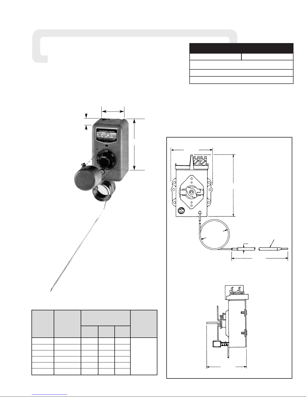
Type ARC Thermal Cutout
Sensing Bulb
with 7’
Standard Capillary
Temperature Maximum
Range
Style
Dia. Length
A.C. Rating
Model
(˚F)
(In.) ±1/2”
(Amps)
ARC-215 60-250˚ 5 3/8 4
ARC-219 60-250˚ 9 3/16 16-1/8
ARC-515 200-550˚ 5 3/8 3-1/4
ARC-519 200-550˚ 9 3/16 11-1/4
ARC-715 300-700˚ 5 3/8 3-11/16
ARC-715D* 300-700˚ 5 3/8 3-11/16
30 Amp
120-277 Vac
Resistive Loads
Single Phase
250 VA
120-277 Vac
(Pilot Duty)
Specifications — Table A
Figure 1
* This model has 15’ capillary
4-3/32”
Length
Dia.
Bulb
(See Specifications — Table A)
2-21/32”
2” O.D.
Typ.Capillary
2-21/32”
3-1/8”
3-3/8”
5-7/8”
Flow Factor~ 216-765-4231
www.flowfactor.com
Page 2
GENERAL
NOTICE: Type ARC Thermal Cutouts are designed for temperature control service only. Because they do not fail safe, they should
not be used for temperature limiting duty.
The system designer is responsible for the safety
of this equipment and should install adequate
back-up controls and safety devices with their
electric heating equipment. Where the consequences of failure could result in personal injury or
property damage, back-up controls are essential.
Principle of Operation — Control action of these thermal cutouts
is provided through the principle of liquid volume change. With a
variation in temperature, the liquid in the sensing bulb expands or
contracts, causing a bellows to actuate the switching mechanism.
Enclosure — The control enclosure and cover assembly is of
heavy-gage electrical grade plastic.
Power Supply — CAUTION: Use on AC only. Thermostat
is not DC rated.
Control Range — The following temperature ranges are available:
Fahrenheit
60˚ to 250˚ 200˚ to 550˚ 300˚ to 700˚
Process Temperature Differential — May be minimized by:
1. Make sure control is mounted to vertical surface. (See Step 1,
MOUNTING section.)
2. Avoid excess heating capacity (oversized heaters).
3. Locate control sensing bulb in optimum position between heat
source and work.
Packing Glands — If a sealed or moisture resistant connection is
required at the point where the capillary enters the oven, tank, pipe
or similar equipment, an appropriate packing gland is available as an
optional part. (Catalog Numbers CCF-25A, CCF-25D or CCF-25E)
FIRE/EXPOSION HAZARD. This thermostat is not
intended for use in hazardous atmospheres where
flammable vapors, gases, liquids or other combustible atmospheres are present as defined in the
National Electrical Code.
Failure to comply can result in personal injury or
property damage.
MOUNTING
Note: Do not mount control where it will be subject to vibration,
shock, grease, dust, lint or corrosive vapors. Do not mount adjacent to a large magnetic contactor, as vibration and shock will
cause thermal cutout to interact erratically — resulting in chattering of the contactor.
The air temperature in and around the control enclosure should
be kept as near to normal room temperature as possible … never
above 150˚F.
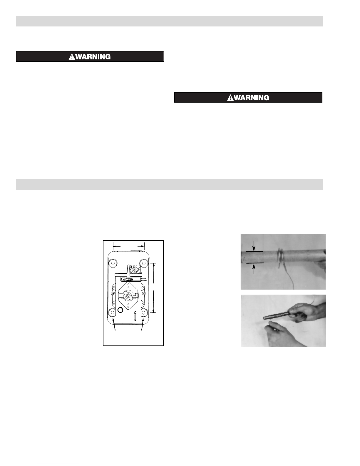
1. Thermal cutout must be mounted
in a vertical position only.
2. Use sheet metal or wood screws
through the four 7/32” diameter
mounting holes in baseplate to
mount control. (See Figure 2.)
3. For controlling platen or die tem-
perature, insert entire sensing bulb
into drilled holes selected for snug
slip fit.
The longer, more sensitive Style 9
bulbs should be used for controlling
air temperatures or pipe line heating.
Note: If material in contact with bulb or
capillary is corrosive, a protective well
should be used. Protective wells are
available at extra cost. Check factory.
4. NOTICE —
A. Bending or deforming sensing bulb will alter control cali-
bration — requiring recalibration after installation. SEE
CALIBRATION section, page 3. If necessary, Style 9
bulbs can be coiled to 1” I.D. (See Figure 3.)
B. Do not kink capillary tube. The resulting constrictions in
fluid flow can destroy control function or broaden temperature differential. Minimum capillary tube bending diameter
is 1/2” I.D. (See Figure 4.)
C. Any deformations of bulb or capillary that result in leakage
of fluid from control renders control inoperative.
D. Avoid passing control capillary tube through zones which
have temperatures in excess of controlled process temperature.
Erratic control or destruction of control function may result.
Figure 2
2-7/16”
Mounting Holes
3-7/8”
1”
Do Not
Bend or Kink
Crimped End
1/2”
Rod
Figure 3
(Sensing Bulb)
Figure 4
(Capillary Tube)
Flow Factor~ 216-765-4231
www.flowfactor.com
Page 3

Figure 8 — When load does not exceed
rating of thermostat.
Figure 9 — Three phase and single phase when load
exceeds rating of thermostat.
Line
Thermostat
Reset Button
Pilot Light
Line
Load
Pilot Light
Reset Button
Thermostat
Control
Circuit
Contactor
Load Line
WIRING
ELECTRIC SHOCK HAZARD. Disconnect all power
before installing or servicing thermostat. Failure
to do so could result in personal injury or property
damage. Thermostat must be installed or serviced
by a qualified person in accordance with the
National Electrical Code, NFPA 70.
1. Electric wiring to the control must be installed in accordance with
the National Electrical Code and with local codes by a qualified
person as defined in the NEC. WARNING: Use copper con-
ductors only.
2. Entrance for wiring is provided by two 1/2” conduit holes in end
of base plate.
3. Remove knob cover. (See Figure 5.)
4. Set thermostat knob to OFF position and then remove knob by lift-
ing knob from shaft. (See Figure 6.)
5. Loosen two screws from end of base plate and remove ther-
mostat cover. (See Figure 7.)
6. Connect wires according to wiring diagrams (Figures 8 and 9).
Note: Electrical connections should be made with generous
loops of wire — approximately 6” per lead.
7. Replace cover, tighten screws, replace dial knob and dial knob
cover.
8. Note: If load amperage or voltage rating exceeds switch rating, a contactor must be used. Contactor and wiring to be supplied by customer. (See Figure 9.)
Figure 5
Figure 6
Figure 7
CALIBRATION
;
Load (Tank, Vat, Die or Platen)
Thermometer
Figure 10
Figure 11
Figure 12
HAZARD OF SHOCK. Extreme care should be exercised during calibration adjustments because of
shock hazard due to exposed electrical terminals.
Disconnect all power before attempting to calibrate cutout.
These controls are factory calibrated to the range indicated on
the control adjustment knob.
If calibration is required, either one of two methods may be fol-
lowed.
A. If accurate measurement standards are not available, the
thermostat can readily be adjusted to a known temperature
standard such as boiling water (212˚F). (See Figure 10.)
B. With the aid of an accurate thermometer or other tempera-
ture measuring device, recalibration may be performed
within the process as in Figure 11.
For either method, the following general calibration procedures
should be followed.
1. Remove knob cover, knob and thermostat housing as per
instructions 3, 4, 5 under WIRING.
2. Replace knob and turn to highest temperature setting.
3. Slowly turn knob when controls click “off”, compare the dial
reading against the thermometer reading.
4. If they do not agree —
A. Set dial knob to thermometer temperature reading and pull
off knob.
B. While holding the adjusting shaft (B) tightly, turn small
center adjusting screw (A) with small screwdriver (C) until
thermostat clicks “off”. (See Figure 12.)
Note: Always use extreme care not to damage the slot in the
center adjusting screw.
C. Each quarter turn of the screw will change the calibration
approximately 30˚F:
— Clockwise to decrease temperature.
— Counterclockwise to increase temperature.
D. Recheck calibration and repeat process if closer calibration
is required.
Adjusting
Set Screw
Screwdriver
Adjusting
Shaft
C
A
B
Flow Factor~ 216-765-4231
www.flowfactor.com
 Loading...