

Page 1
Installation & Operation Manual
1020 & 1030
Temperature Controllers
PK552
0037-75578
August 2018
i
Page 2

Page 3

Safety and Warranty Information
Products covered in this issue of the manual: 1020 &
1030 Process and Over-Temperature Controllers.
This manual supplements the Quick Start Product
manual supplied with each instrument at the time of
shipment. Information in this installation, wiring and
operation manual is subject to change without notice.
Copyright © August 2015, Chromalox Corporation, all
rights reserved. No part of this publication may be reproduced, transmitted, transcribed or stored in a retrieval system, or translated into any language in any
form by any means without the written permission of
Chromalox.
Copies of this manual are available in electronic format
on the Chromalox web site (www.chromalox.com) .
THE INTERNATIONAL HAZARD SYMBOL IS INSCRIBED ADJACENT TO THE REAR CONNECTION TERMINALS
IT IS IMPORTANT TO READ THIS MANUAL BEFORE INSTALLING OR COMMISSIONING THE
UNIT.
WARNING: PRODUCTS COVERED BY THIS MANUAL ARE SUITABLE FOR INDOOR USE, INSTALLATION CATEGORY II, POLLUTION CATEGORY
2 ENVIRONMENTS
THIS SYMBOL MEANS THE EQUIPMENT IS PROTECTED THROUGHOUT
BY DOUBLE INSULATION.
Warranty and Returns Statement
These products are sold by Chromalox under the warranties set forth in the following paragraphs. Such warranties are extended only with respect to a purchase
of these products, as new merchandise, directly from
Chromalox or from a Chromalox distributor, representative, or reseller and are extended only to the first
buyer thereof who purchases them other than for the
purpose of resale.
Warranty
These products are warranted to be free from functional defects in material and workmanship at the time the
products leave Chromalox factory and to conform at
that time to the specifications set forth in the relevant
Chromalox instruction manuals sheet or sheets, for
such products for a period of three years.
THERE ARE NO EXPRESSED OR IMPLIED WARRANTIES, WHICH EXTEND BEYOND THE WARRANTIES HEREIN AND ABOVE SET FORTH. CHROMALOX MAKES NO WARRANTY OF MERCHANTABILITY
OR FITNESS FOR A PARTICULAR PURPOSE WITH
RESPECT TO THE PRODUCTS.
Limitations
Chromalox shall not be liable for any incidental damages, consequential damages, special damages, or any
other damages, costs or expenses excepting only the
cost or expense of repair or replacement as described
above. Products must be installed and maintained in
accordance with Chromalox instructions. There is no
warranty against damage to the product resulting from
corrosion. Users are responsible for the suitability of
the products to their application. For a valid warranty
claim, the product must be returned carriage paid to
the supplier within the warranty period. The product
must be properly packaged to avoid damage from
Electrostatic Discharge or other forms of harm during
transit.
iii
Page 4

Table of Contents
Contents Page Number
Safety & Warranty .................................................................................................................................................. iii
Chapter 1 Installation ............................................................................................................................................. 1
1.1 Unpacking .................................................................................................................................................... 1
1.2 Cleaning ....................................................................................................................................................... 1
1.3 Installation .................................................................................................................................................... 1
Chapter 2 Electrical Installation ............................................................................................................................ 2
2.1 Installation Considerations .......................................................................................................................... 2
2.2 AC Power Wiring .......................................................................................................................................... 2
2.3 Wire Installation ............................................................................................................................................ 2
2.4 Use of Shielded Cable ................................................................................................................................. 2
2.5 Noise Suppression at Source ...................................................................................................................... 2
2.6 Sensor Placement ........................................................................................................................................ 3
2.7 Panel Wiring ................................................................................................................................................. 3
2.8 Terminal Wiring ............................................................................................................................................ 4
2.9 Power Connection ....................................................................................................................................... 4
Chapter 3 Powering Up .......................................................................................................................................... 7
3.1 Powering Up Procedure ............................................................................................................................... 7
3.2 First Power Up or Factory Default ............................................................................................................... 7
3.3 Auto-Tune .................................................................................................................................................... 7
3.4 Front Panel ................................................................................................................................................... 7
3.5 General Navigation & Editing ....................................................................................................................... 8
3.6 Mode (or Menu) Structure ............................................................................................................................ 8
3.7 Returning to Perator Mode .......................................................................................................................... 8
3.8 Mode and Access and Lock Codes ............................................................................................................. 8
3.9 Use of the Controller for Non-Temperature Applications.............................................................................8
3.10 Controller Transmitter Function ................................................................................................................. 8
3.11 User Mode & Screens on Standard & Extruction models .......................................................................... 9
3.12 Warnings & Messages ............................................................................................................................ 10
Chapter 4 Initial Default Settings ........................................................................................................................ 12
4.1 Factory Reset Procedure ........................................................................................................................... 12
Chapter 5 Setup Mode ......................................................................................................................................... 13
5.1 Navigating the Setup Screens ................................................................................................................... 13
Chapter 6 Advanced Configuration Mode ......................................................................................................... 15
Chapter 7 User Mode ........................................................................................................................................... 16
7.1 User Menu ................................................................................................................................................. 16
7.2 Input Menu ................................................................................................................................................. 17
7.3 User Calibration Menu ............................................................................................................................... 18
7.4 Outputs Menu ............................................................................................................................................ 18
7.5 Control Menu (Standard Model) ................................................................................................................. 19
7.6 Control Menu (Extrusion Model) ................................................................................................................ 20
7.7 Setpoint Menu (Standard Model) ............................................................................................................... 21
7.8 Setpoint Menu (Extrusion Model) .............................................................................................................. 21
7.9 Alarm Menu ................................................................................................................................................ 22
7.10 Communications Menu ............................................................................................................................ 22
7.11 Display Menu ........................................................................................................................................... 23
7.12 Operator Screens Menu ........................................................................................................................... 23
7.13 Information Menu ..................................................................................................................................... 23
7.14 Exiting the Advanced Configuration Mode .............................................................................................. 23
iviv
Page 5

Contents Page Number
Chapter 8 Calibration Mode ................................................................................................................................ 24
8.1 Single Point Calibration (PV Offset) ........................................................................................................... 24
8.2 Two Point Calibration ................................................................................................................................. 24
8.3 Base Input Calibration ............................................................................................................................... 25
8.4 Calibration Check ...................................................................................................................................... 25
8.5 Base Calibration Procedure ....................................................................................................................... 26
8.6 Calibrating the mV Input ............................................................................................................................ 25
8.7 Calibrating Other Input Types .................................................................................................................... 26
8.8 Calibration Input States ............................................................................................................................. 26
8.9 Calibration Progress .................................................................................................................................. 26
8.10 Calibration Modbus Addresses ............................................................................................................... 26
Chapter 9 Automatic Tuning ................................................................................................................................ 27
9.1 Running the Pre-Tune ................................................................................................................................ 27
9.2 Running Tune at SP ................................................................................................................................... 27
9.3 Tuning at SP Troubleshooting .................................................................................................................... 27
9.4 Tuning at SP for Heat and Cool ................................................................................................................. 28
Chapter 10 Digital Input Operation ..................................................................................................................... 29
Chapter 11 Timer Feature .................................................................................................................................... 31
11.1 Timer Feature ........................................................................................................................................... 31
11.2 Delay, Ramp & Timer Diagram ................................................................................................................. 31
Chapter 12 Extrusion Model Only Features ....................................................................................................... 32
12.1 Non-Linear Cooling Function ................................................................................................................... 32
12.2 Method ..................................................................................................................................................... 32
12.3 Parameter Adjustment ............................................................................................................................. 34
12.4 Soft Start Function ................................................................................................................................... 34
12.5 Extrusion Only Parameters in the Control Menu...................................................................................... 35
Chapter 13 Limiter Models .................................................................................................................................. 36
13.1 Introduction to the Limiter Model ............................................................................................................ 36
13.2 Limiter Modbus Communications ............................................................................................................ 36
13.3 Limiter Digital Input .................................................................................................................................. 36
13.4 Limiter Operator Mode & Screens ........................................................................................................... 37
13.5 Limiter Output Latching ........................................................................................................................... 37
13.6 Limiter Setup Mode Parameters .............................................................................................................. 37
13.7 Limiter Advanced Configuration Parameters ........................................................................................... 40
13.8 Limiter Input Menu ................................................................................................................................... 40
13.9 Limiter User Calibration Menu ................................................................................................................. 40
13.10 Limiter Outputs Menu ............................................................................................................................ 41
13.11 Limiter Communications Menu .............................................................................................................. 43
13.12 Limiter Display Menu ............................................................................................................................. 43
13.13 Limiter Information Menu ....................................................................................................................... 43
13.14 Limiter Exiting from Advanced Configuration Mode .............................................................................. 43
Chapter 14 Configuration Software .................................................................................................................... 44
14.1 Introduction .............................................................................................................................................. 44
14.2 Connectivity Requirements ...................................................................................................................... 44
14.3 Installing & Accessing the Configuration Program .................................................................................. 45
14.4 Getting Started ........................................................................................................................................ 45
14.5 Troubleshooting the Series 20 Configurator ............................................................................................ 46
14.6 Getting Started (continued) ...................................................................................................................... 47
14.7 Navigating the Configurator ..................................................................................................................... 48
vv
Page 6

Contents Page Number
Chapter 15 Serial Communications .................................................................................................................... 51
15.1 Supported Protocol ................................................................................................................................. 51
15.2 RS485 Configuration ................................................................................................................................ 51
15.3 RS485 Device Addressing ....................................................................................................................... 51
15.4 Link Layer ................................................................................................................................................. 51
15.5 Supported Modbus Functions ................................................................................................................. 52
15.6 Function Descriptions .............................................................................................................................. 52
15.7 Function 03/04 Read Holding/Input Registers ........................................................................................ 52
Chapter 16 Modbus Addresses ........................................................................................................................... 54
16.1 Input Parameters ..................................................................................................................................... 54
16.2 Standard Extrusion Modbus Addresses .................................................................................................. 55
16.3 Limiter Modbus Addresses ...................................................................................................................... 63
Chapter 17 Specifications ................................................................................................................................... 68
Chapter 18 Glossary ............................................................................................................................................. 70
Chapter 19 Order Tables ...................................................................................................................................... 78
vi
Page 7
1 Installation
)
4.76”
1.1 Unpacking
Carefully remove the product from its packing. Please
retain the packing for future use.
A single sheet concise manual is also supplied in one
or more languages. Examine the delivered items for
damage or defects. If any are found, contact your supplier immediately.
1.2 Cleaning
Clean the front panel by wiping down with a dry cloth.
Never allow water or any other substances to ingress
into the instrument.
1.3 Installation
Installation should only be performed by technically competent personnel. It is the responsibility of the installing engineer to ensure that
the configuration is safe. Local regulations
regarding electrical installation & safety must
be observed (e.g. US National Electrical Code
(NEC) or Canadian Electrical Code.
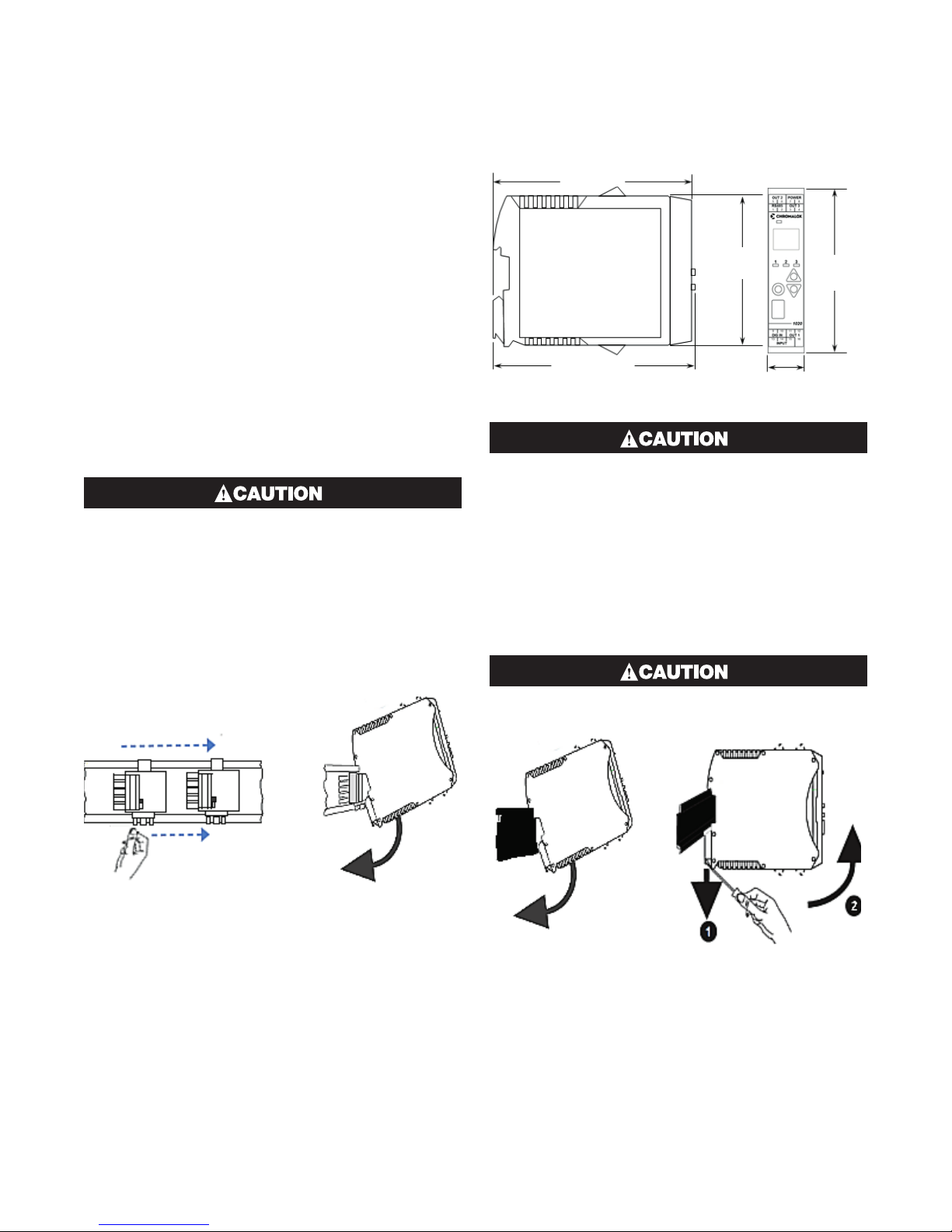
This instrument is designed for indoor back of panel
use.
(121 mm)
3.90”
(99 mm)
4.84”
(123 mm)
This equipment is protected throughout by
double insulation, when installed properly.
This type of installation does not need an earth
connection, but it is vital for safety reasons,
that the instrument is replaced if the instrument housing is broken.
The optional bus connection should be slid onto the
DIN Rail before fitting the 1020/1030 Rail.
The connectors must be pushed together to share the
bus.
0.89”
(22.5 mm)
4.21”
(107 mm
This bus connection links up the optional RS485 communications connections without extra wiring but does
not supply power.
Ensure there is adequate air flow inside the
panel to prevent overheating.
11
Page 8

2 Electrical Installation
The installation should be only performed by
technically competent personnel.
It is the responsibility of the installing engineer
to ensure that the configuration is safe.
Local Regulations regarding electrical installation & safety must be observed (e.g. US National Electrical Code (NEC) or Canadian Electrical
Code).
2.1 Installation Considerations
Ignition transformers, arc welders, motor drives, mechanical contact relays and solenoids are examples of
devices that generate electrical noise in typical industrial environments.
The following guidelines MUST be followed to minimise their effects.
If the instrument is being installed in existing equipment, the wiring in the area should be checked to ensure that good wiring practices have been followed.
Noise-generating devices such as those listed above
should be mounted in a separate enclosure.
If this is not possible, separate them from the instrument, by the largest distance possible.
If possible, eliminate mechanical contact relays and
replace with solid-state relays. If a mechanical relay
cannot be replaced, a solid-state relay can be used to
isolate the instrument.
A separate isolation transformer to feed only the instrumentation should be considered. The transformer
can isolate the instrument from noise found on the AC
power input.
2.2 AC Power Wiring - Neutral (for
100 to 240V AC versions)
It is good practice to ensure that the AC neutral is at or
near ground (earth) potential. A proper neutral will help
ensure maximum performance from the instrument.
2.3 Wire Isolation
Four voltage levels of input and output wiring may be
used with the unit:
• Analogue input (for example thermocouple, RTD,
VDC, mVDC or mADC)
• Relays outputs
• SSR Driver outputs
• AC power
The only wires that should run together are
those of the same category.
If any wires need to run parallel with any other lines,
maintain a minimum space of 6” between them. If wires
MUST cross each other, ensure they do so at 90 degrees to minimize interference.
2.4 Use of Shielded Cable
All analog signals must use shielded cable. This will
help eliminate electrical noise induction on the wires.
Connection lead length must be kept as short as possible keeping the wires protected by the shielding. The
shield should be grounded at one end only. The preferred grounding location is at the sensor, transmitter
or transducer.
2.5 Noise Suppression at Source
Usually when good wiring practices are followed, no
further noise protection is necessary. Sometimes in
severe electrical environments, the amount of noise is
so great that it must be suppressed at source. Many
manufacturers of relays, contactors, etc. will supply
‘surge suppressors’ which mount on the noise source.
For those devices that do not have surge suppressors
supplied, Resistance-Capacitance (RC) networks and/
or Metal Oxide Varistors (MOV) may be added.
2
Page 9
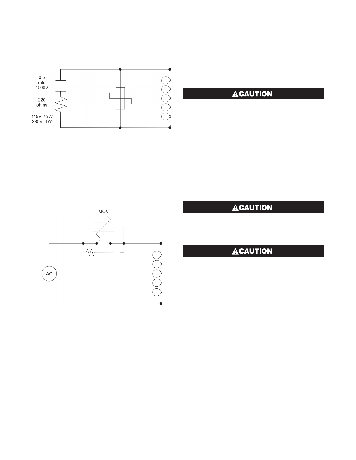
Inductive coils: - MOVs are recommended for transient suppression in inductive coils, connected in parallel and as close as possible to the coil. Additional
protection may be provided by adding an RC network
across the MOV.
Figure 5. Contacts: - Arcing may occur across contacts when they open and close. This results in electrical noise as well as damage to the contacts. Connecting a properly sized RC network can eliminate this arc.
For circuits up to 3 amps, a combination of a 47 ohm
resistor and 0.1 microfarad capacitor (1000 volts) is
recommended. For circuits from 3 to 5 amps, connect
two of these in parallel.
2.6 Sensor Placement (Thermocouple or
RTD)
If the temperature probe is to be subjected to corrosive
or abrasive conditions, it must be protected by an appropriate thermowell. The probe must be positioned to
reflect true process temperature: In a liquid media, the
most agitated area. In air, the best circulated area.
The placement of probes into pipe work some
distance from the heating vessel leads to transport delay, which results in poor control.
For a two wire RTD a wire link should be used in place
of the third wire. Two wire RTDs must only be used with
lead lengths less than 3 meters (10 ft.). Use of three
wire RTDs is strongly recommended.
2.7 Panel Wiring
In general, all wiring connections are made to the instrument after it is installed. Copper wires must be
used for all connections (except thermocouple signal
wires).
To avoid electrical shock, AC power wiring
must not be connected to the source distribution panel until all wiring procedures are completed.
Check the information label on the case to determine the correct voltage before connecting
to a live supply.
3
Page 10
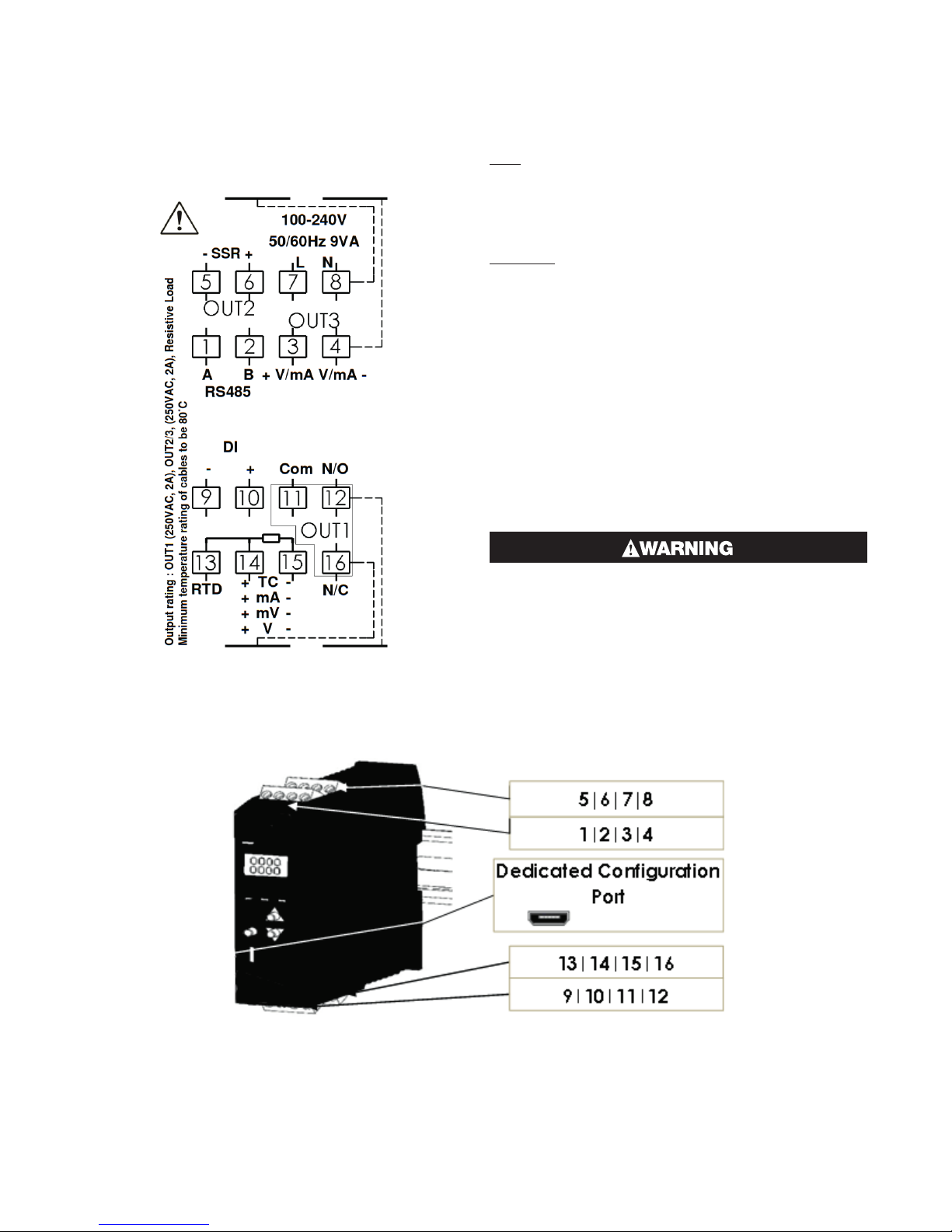
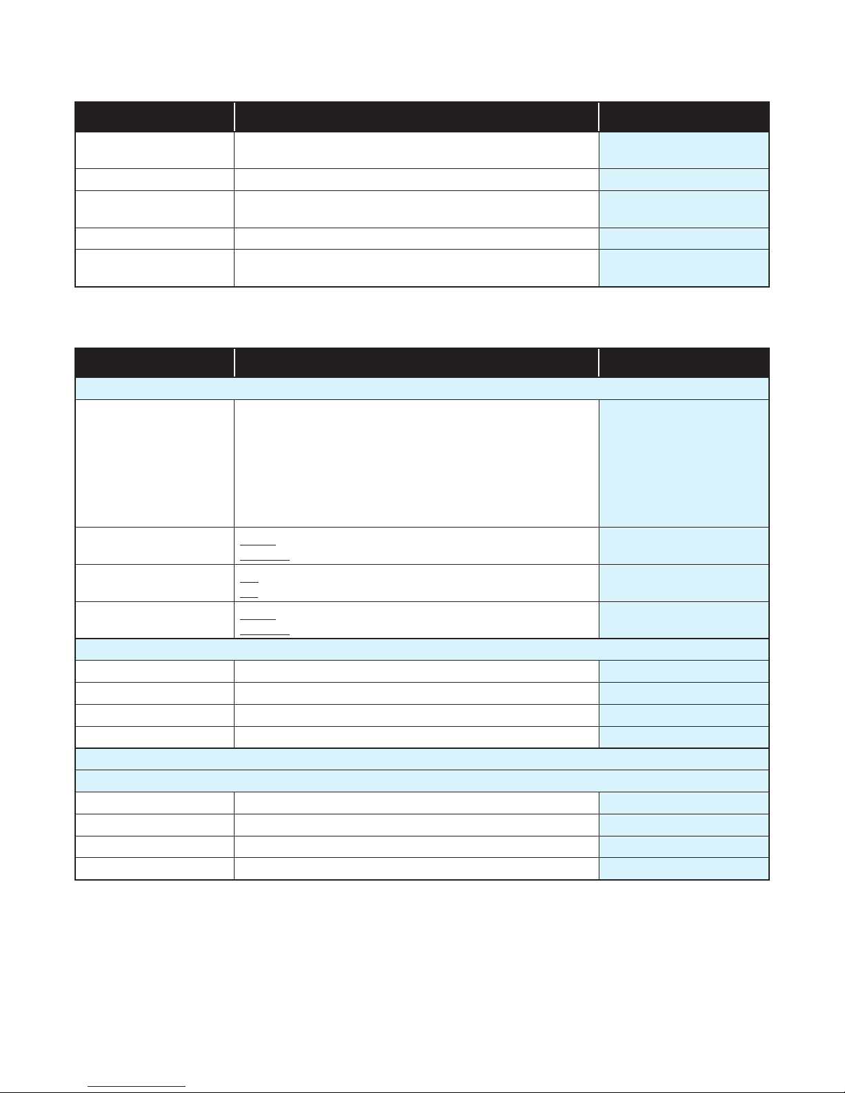
2.8 Terminal Wiring
The diagram shows all possible option combinations.
Please check the product configuration before wiring.
Dedicated Configuration Socket (on bottom of the instrument)
The wiring label shows the power requirements, connector positions and terminal number.
This example is:
TOP
1 & 2 Rear = RS485 Comms
3 & 3 Rear = Linear Out 3
5 & 6 Front = SSR Driver Out 2
7 & 8 Front = 100-240VAC power.
BOTTOM
9 & 10 Rear = Digital Input
11, 12 Rear & 16 Front = Relay Out 1
13, 14 & 15 Front = Process Input
2.9 Power Connection
To avoid damaging your instrument it is critical the
power connection is made to the correct terminals
Power is connected to pins 7 & 8.
Top, rear connector on the right-hand side.
(front connector omitted from picture for clarity)
The green LED shows when power is correctly connected.
NEVER DIRECTLY CONNECT THIS SOCKET TO
A USB PORT.
A configuration socket to USB adaptor can be obtained
from your supplier.
4
Page 11
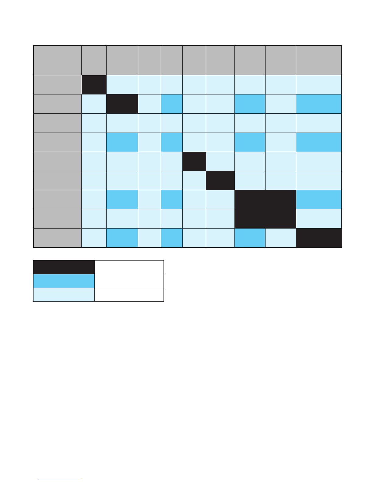
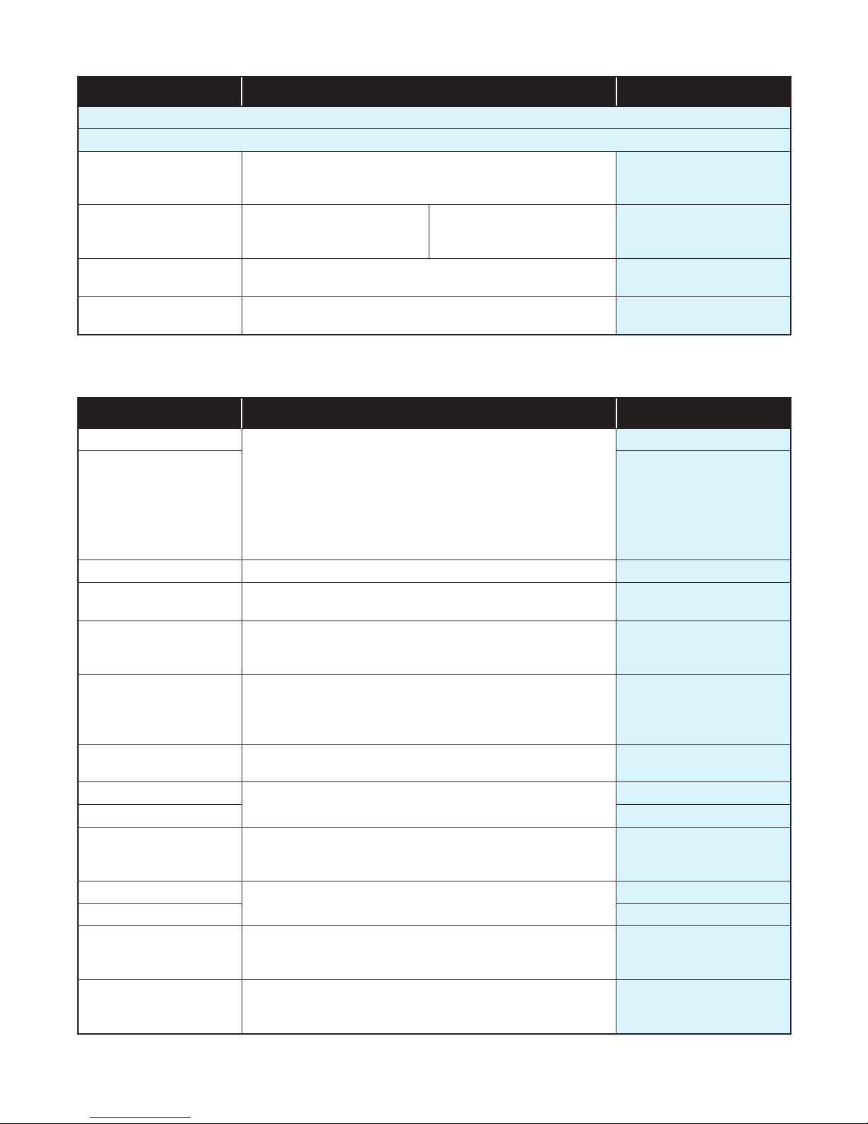
1020/1030 Rail Isolation Chart
Universal
PSU
PSU
Input Relay SSR Linear
RS485
Comms
Non-
Isolated
Digital
Input
Isolated
Digital
Input
Configuration
Port
Universal
Input
Relay
SSR
Linear
RS485 Comms
Non-Isolated
Digital Input
Isolated
Digital Input
Configuration
Port
Not Applicable
No Isolation
Reinforced Isolation
5
Page 12
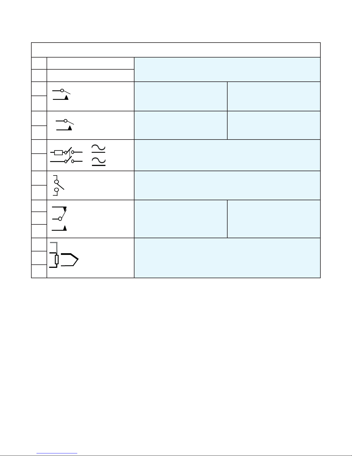
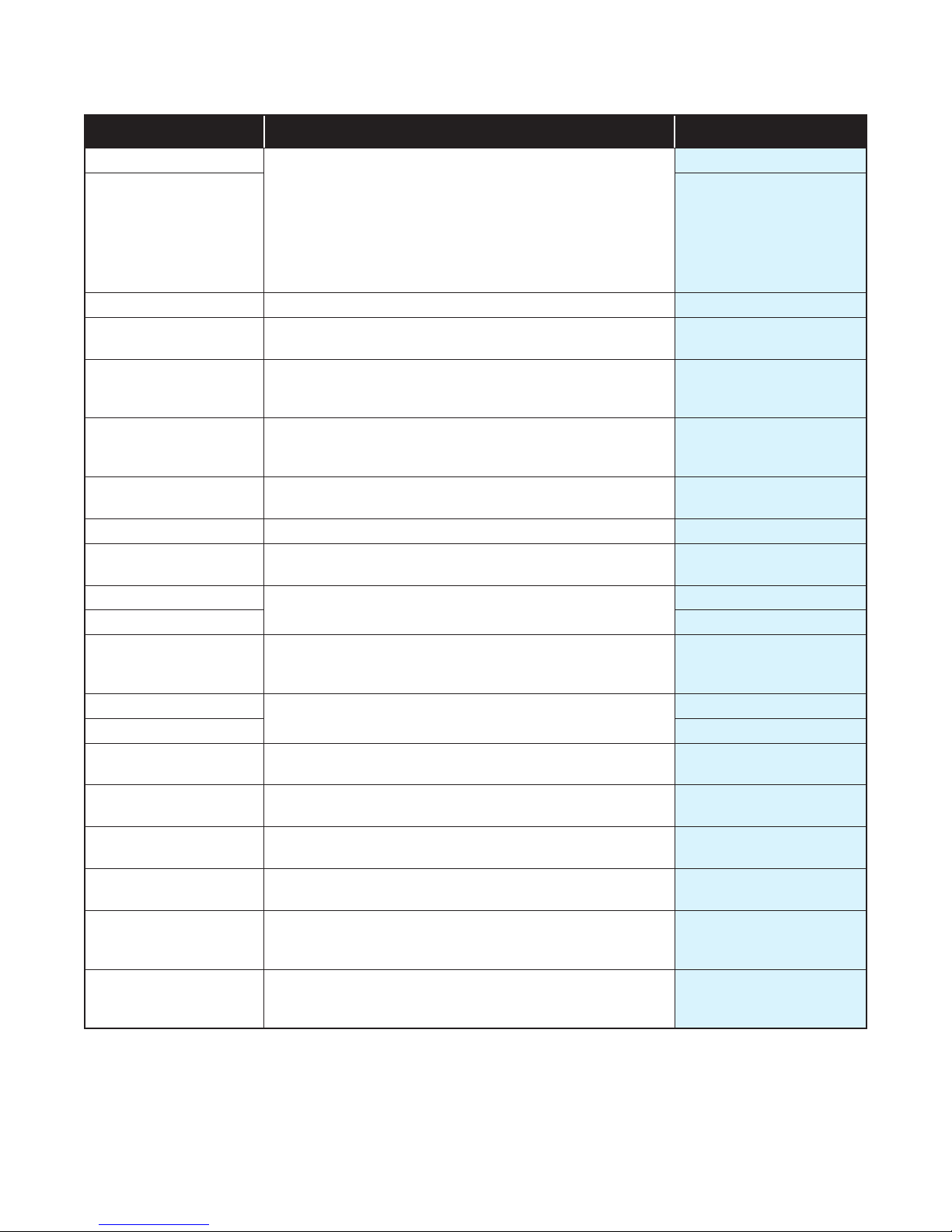
1020/1030 Input & Output Map
Relay COM / Linear +
Relay COM / Linear +
Relay NO / Linear -
-
+
Relay COM / Linear +
Relay NO / Linear -
Relay COM / SSR -
Relay NO / SSR+
L +
N -
Relay COM / Linear +
Relay NO / Linear -
Relay COM / SSR -
Relay NO / SSR+
L +
N -
Relay COM / Linear +
Relay NO / Linear -
+
-
Volt-free or TTL
compatible
Relay COM / SSR -
Relay NO / SSR+
Relay NC
L +
N -
Relay COM / Linear +
Relay NO / Linear -
+
-
Volt-free or TTL
compatible
Relay COM / SSR -
Relay NO / SSR+
Relay COM / SSR -
Relay NO / SSR+
Relay NC
Use cables with 80°C minimum temperature rating, conductor sizes 30-12 AWG
1
2
3
4
5
6
7
8
9
10
16
11
12
RS485 A (Rx/Tx+)
RS485 B (Rx/Tx-)
Relay NO / Linear -
Relay COM / SSR
Relay NO / SSR+
+
Volt-free or TTL
compatible
-
Relay COM / SSR -
Relay NO / SSR+
Output 3 – Standard & Extrusion
models
Output 2 – Standard & Extrusion
models
L
Power – low power or mains (hardware dependent)
N -
Output 1 – Standard and
Extrusion models
Communications
Output 3 (Alarm 2 or Retx PV) –
Limiter model
Alarm 1 output – Limiter model
Digital Input
Limit output – Limiter model
(Relay only)
13
14
15
RTD
TC / RTD / Linear
TC / RTD / Linear
Input – thermocouple, RTD or linear
6
Page 13
3 Powering Up
ENSURE SAFE WIRING PRACTICES HAVE BEEN
FOLLOWED. WHEN POWERING UP FOR THE
FIRST TIME, DISCONNECT THE OUTPUT CONNECTIONS.
3.2 First Power Up or Factory De-
fault
When the unit is initially powered up or the user restores
the factory defaults to the device, it immediately enters
the Setup menu without requiring an unlock code. The
user must then cycle through every parameter, to either
view or adjust the value, and then exit the menu.
Check carefully the supply voltage and connections before applying power.
The instrument must be powered from a supply according to the wiring label on the side of the unit. (100vac
to 240Vac, or 24 Vac/dc depending upon the model
purchased.)
3.1 Powering Up Procedure
At power-up, a self-test procedure is run, during which
a product logo screen is displayed.
When powering up for the first time the instrument
starts up in the Setup Mode after the product logo
screen is displayed.
You must complete the Setup by
cycling through all of the parameters
before using the device for the first
time.
1. Use or to review every parameter.
2. Change value if necessary using , then
use or to adjust the value, then to save.
3. Exit Setup by pressing & together.
If the above steps are not followed the Setup has not
been completed so the device will go into Setup, again,
on every subsequent power up.
3.3 Auto-Tune
The controller can be auto-tuned from the Setup Mode.
1. Pre-tune
2. Auto-tune at setpoint
Auto-Tuning will not engage if:
• Controller is set to On/Off Control
• Setpoint is ramping
• PV is within 5% of the input range
from setpoint
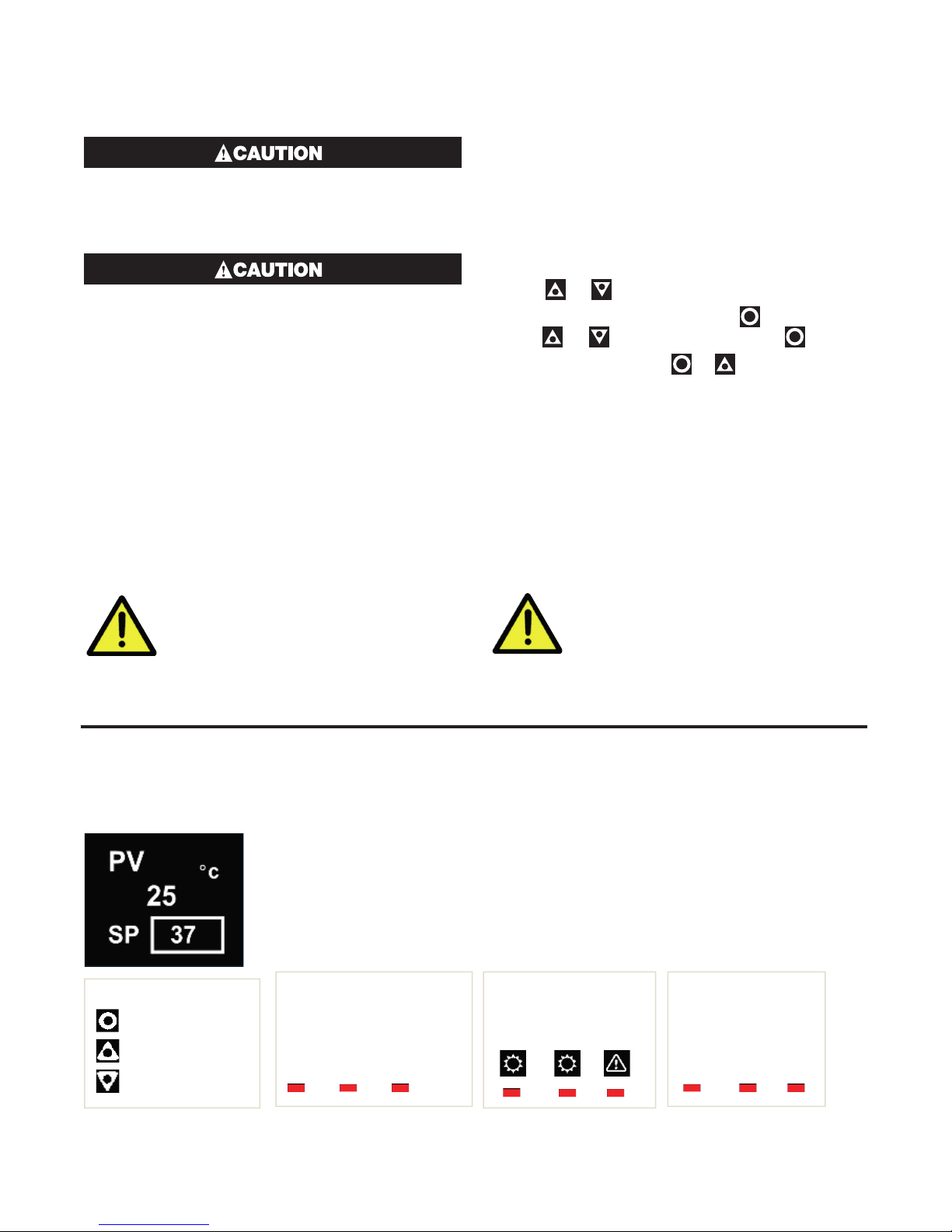
3.4 Front Panel
Display shows PV (process variable), units, SP (setpoint), alarm/latch statuses,
error & warning messages.
By default, the display turns off after 5 minutes without any key presses.
3 navigation keys:
Ok/Select
Up
Down
This is configurable in the Advanced Configuration, in the Display submenu, parameter Screen Timeout. Any key press turns the display back on.
Standard:
3 Output Status LEDs
1 2 3
Extrusion:
3 Status LEDs for:
Heat Cool Alarm
7
Limiter:
3 Status LEDs for
LM EX AL
Page 14
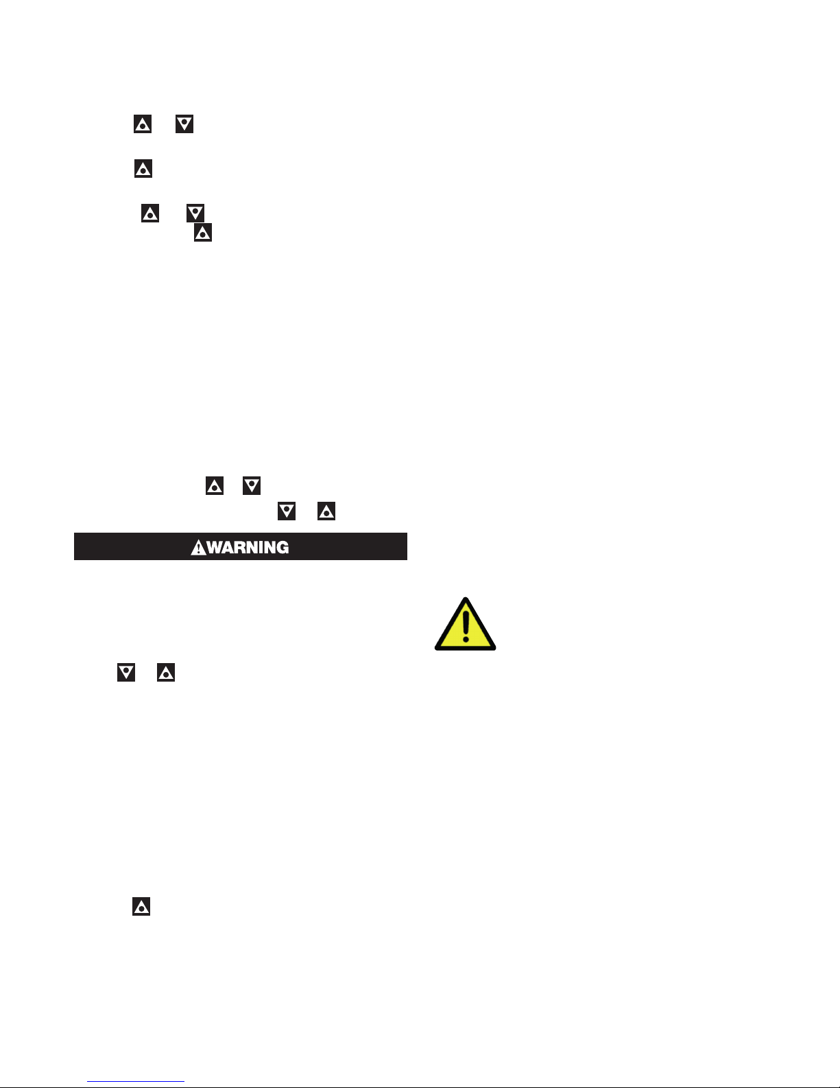
3.5 General Navigation & Editing
• Press or keys to navigate between parameters or menu items.
• Press to highlight a parameter value, ready for
editing.
• Press or to change the parameter value, then press within 60 seconds to confirm
change.
3.6 Mode (or Menu) Structure
There are 3 main modes (or menus) on the device –
Setup and Advanced Configuration Mode.
• User Mode - the live screen used for normal operation. The process variable can always be seen in
this mode
• Setup Mode – allows access to the most important
parameters
• Advanced Configuration Mode - access all parameters via sub-menus
Setup Mode - press & .
Advanced Configuration - press & .
Never connect the instrument’s configuration
socket directly to a USB port as it will damage
the controller.
3.7 Returning to Operator Mode
3.9 Use of the Controller for NonTemperature Applications
In the majority of applications this controller will be
used for temperature sensing, either via a sensor or a
linear DC input, which use heat and cool. However this
controller can be used for other types of processes.
If your process is not a temperature then the parameters labelled as “HEAT”refer to reverse acting outputs
used to increase the process value and “COOL” to decrease the process value.
As an example you may have a system that reads and
controls humidity. The “HEAT” output drives the humidifier and the “COOL” output drives the de-humidifier. Use the “HEAT” parameters to control the humidifier
and the “COOL” parameters to control the de-humidifier.
Often the “HEAT” and “COOL” is referred to as “Primary” and “Secondary” on other controllers.
3.10 Controller Transmitter Function
The Standard 1020 & 1030 model can be used as a
“transmitter” to retransmit the process value or controller setpoint via Output 3, if the linear option is fitted.
The parameter Usage in the Linear Output sub-menu
can be set to PV Retransmit or SP Retransmit.
In the Display menu, the parameter Transmitter can be
used to enable Transmitter view. This hides the Setpoint from view.
Control functions will remain active if
they have been configured.
Press & to move back one level
From a sub-menu you will need to do this twice; once
to return to Advanced Configuration Mode then again
to exit. After 120 seconds without key presses the unit
returns automatically to the first Operator mode screen.
3.8 Mode Access and Lock Codes
Separate lock codes can be set for the Setup mode
and for the Advanced Configuration mode.
• Setup mode lock code – default 10.
• Advanced Configuration mode lock code – default
20.
Hold the button while powering up for a read-only
view of lock codes.
8
Page 15
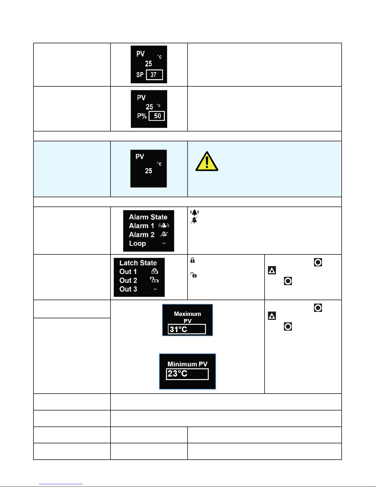
3.11 User Mode & Screens on Standard & Extrusion models
User Screen Temperature Unit.
PV – process variable (e.g. process temperature)
SP - Setpoint
Manual control
Transmitter screen is present on Standard model only.
Important: The following parameters are only displayed if set to “Show” in the User sub-menu.
Alarm State
Latch State
PV – process variable (e.g. process temperature)
Manual Power is shown as P%.
Transmitter parameter = Enable, SP is hidden.
The device still functions as a controller
To act as a PV transmitter the parameter Usage in the
Linear Output sub-menu needs to be set to PV Retransmit.
Alarm triggered
Alarm configured, but not triggered
– Alarm not set
Output Latched
Latch configured, but
output not Latched
using the local Setpoint.
To clear press
to select Yes.
Press to accept.
then
– Latch not set
Maximum PV
Minimum PV
Screens show the Maximum & Minimum PV reached.
Control Enable OFF - Control output(s) disabled. (Ignored when in manual mode).
ON - Control output(s) enabled.
Manual Control Enable OFF - Automatic control, PID or On-Off control available.
ON - Manual control, Manual Power shown as P% xxx
Time On Remaining On Timer Visible when On Timer is active.
See Ramp & Timers diagram.
Delay Time Remaining Delay Timer Visible when Delay Timer is active.
See Ramp & Timers diagram.
9
To clear press then
to select Yes.
Press
to accept.
Page 16

3.12 Warnings & Messages
Pop-Up Alerts
Pop-up alerts appear in front of the current screen.
They must be acknowledged before you can access
other screens.
Pop-Up Alert List
Message Description
Press
& together to clear the pop-up alert.
Alarm 1
Alarm 2
Alarm 1 & 2
Control Enabled
Calibration Pass
Calibration Fail
Tuning in Progress
Setup not completed
Offset in use
Limit Exceeded
Tune Error
PV within 5% of SP
Tune Error
Setpoint is ramping
Tune Error
Control is ON/OFF
Tune Error
Control is manual
Tune Error
Tune at Setpoint not able to run
Tune Error
Sensor Break
Tune Error
Timer Running
Alarm 1 is active.
Alarm 2 is active.
Alarm 1 and 2 are active.
Alerts user that the control is re-enabled. (not Limiter.)
Factory calibration (Full Input Calibration has passed.)
Factory calibration (Full Input Calibration has failed.)
Tune at Setpoint or Pre-Tune is running. (Not Limiter.)
Please refer to First Power Up or Factory Default section.
SP offset is being used in Setpoint sub-menu.
Limiter only, indicates when the limit value has been exceeded.
PV within 5% of the scale range input from SP (for Pre-Tune). Try a different
setpoint or narrow the scale range input.
Setpoint is ramping. Turn off ramping and try again.
Control is not set to PID, i.e. the proportional band = 0. Set the proportional
band to any other value and try again.
Manual control enabled. Set Manual Control Enable to OFF and try again.
Tune at setpoint has timed out or cannot run.
Check your sensor.
Timer Running. Set the Enable Timer parameter to Disabled.
10
Page 17
Message List
Message Description
ALARM
LATCH
LIMIT
HIGH
LOW
OPEN
ERROR
TUNE
P%
Ramp
Alternates with PV and shows one, or both, Alarms are active.
Alternates with PV, one or more outputs are latched on & no alarm is active.
On Limiter model, alternates with PV to show Limit is active.
Process variable input >5% over-range.
Check for possible issues with sensor or connections.
Also, check that Scale Range Maximum is high enough for your application.
Process variable input >5% under-range.
Check for possible issues with sensor or connections.
Also, check that Scale Range Minimum is low enough for your application.
Break detected in process variable input sensor, wiring or wrong input type selected.
Shows OPEN until resolved, Control is disabled on Standard or Extrusion models), or
Limit state set until resolved on Limiter model.
Selected input range is not calibrated.
Shows ERROR until resolved. Control is disabled on Standard or Extrusion models),
or Limit state set until resolved on Limiter model.
Alternating with SP shows Auto-tuning is in progress.
Manual power value replaces setpoint, shows P% xxx of power.
Setpoint ramp is active (alternates with actual setpoint).
Control is disabled. Control output(s) are off.
OFF
Enable control by setting Control Enable to ON or check state of the Digital Input if
Digital I/P Action is set to Ctrl Enable/Disable.
DELAY
Shows when Delay Timer is active, control is off until the timer finishes.
The Automatic Tuning parameter must be changed to Off to clear any tuning message.
Display alternates between the tuning code & setpoint
tErr1
tErr2
tErr3
tErr4
tErr5
tErr6
tErr7
tErr8
PV within 5% of the scale range input from SP (for Pre-Tune).
Try a different setpoint or narrow the scale range input.
Setpoint is ramping.
Control is ON/OFF. Control is not set to PID, i.e. the proportional band = 0.
Control is manual. Set Manual Control Enable to OFF.
Tune at Setpoint not able to run.
Sensor Break.
Timer Running. Set the Enable Timer parameter to Disabled before attempting to run
tuning again.
Control is disabled. Please check it is safe to enable control and then go to the User
menu to change Control Enable to ON.
11
Page 18
4 Initial Default Settings
Your 1020 & 1030 Process and Over-temperature Controller will arrive with specific factory settings. If at any
point the factory default process is performed, all the
parameters will be returned to the values shown below.
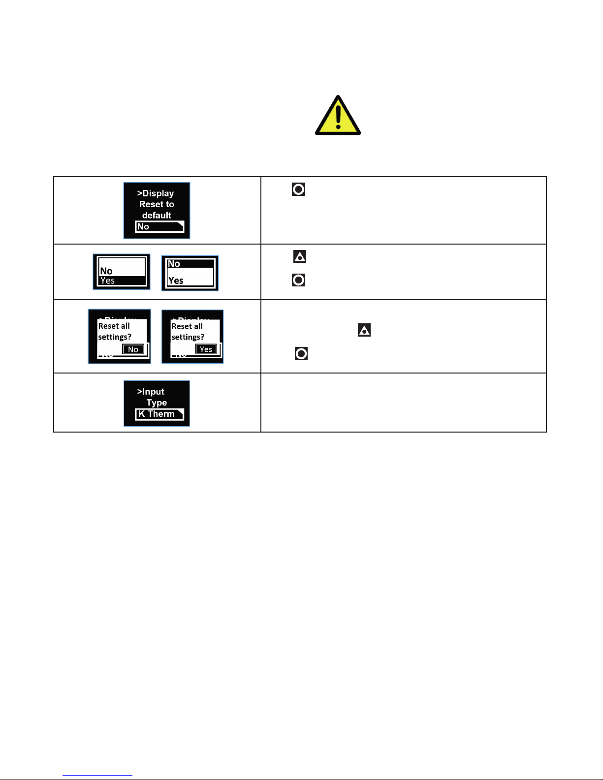
4.1 Factory Reset Procedure
Press to highlight NO.
Press to move highlight to YES.
Press to accept.
A confirmation screen appears.
If you are sure press to show YES (leave as NO to cancel).
Press to confirm your choice.
The instrument shows the default for the Input Type and its
default value.
The Reset to Defaults can be found in
the sub-menu Display in the Advanced
Configuration on all models.
The user must review all parameters in the Set-up menu before
exiting.
12
Page 19
5 Setup Mode
5.1 Navigating the Setup Screens
To access the Setup Mode from User Mode, press
& together. Enter code for Setup Lock (default = 10)
using & , then press .
Lock Code 10 Lock code to enter Setup Mode. Default is 10
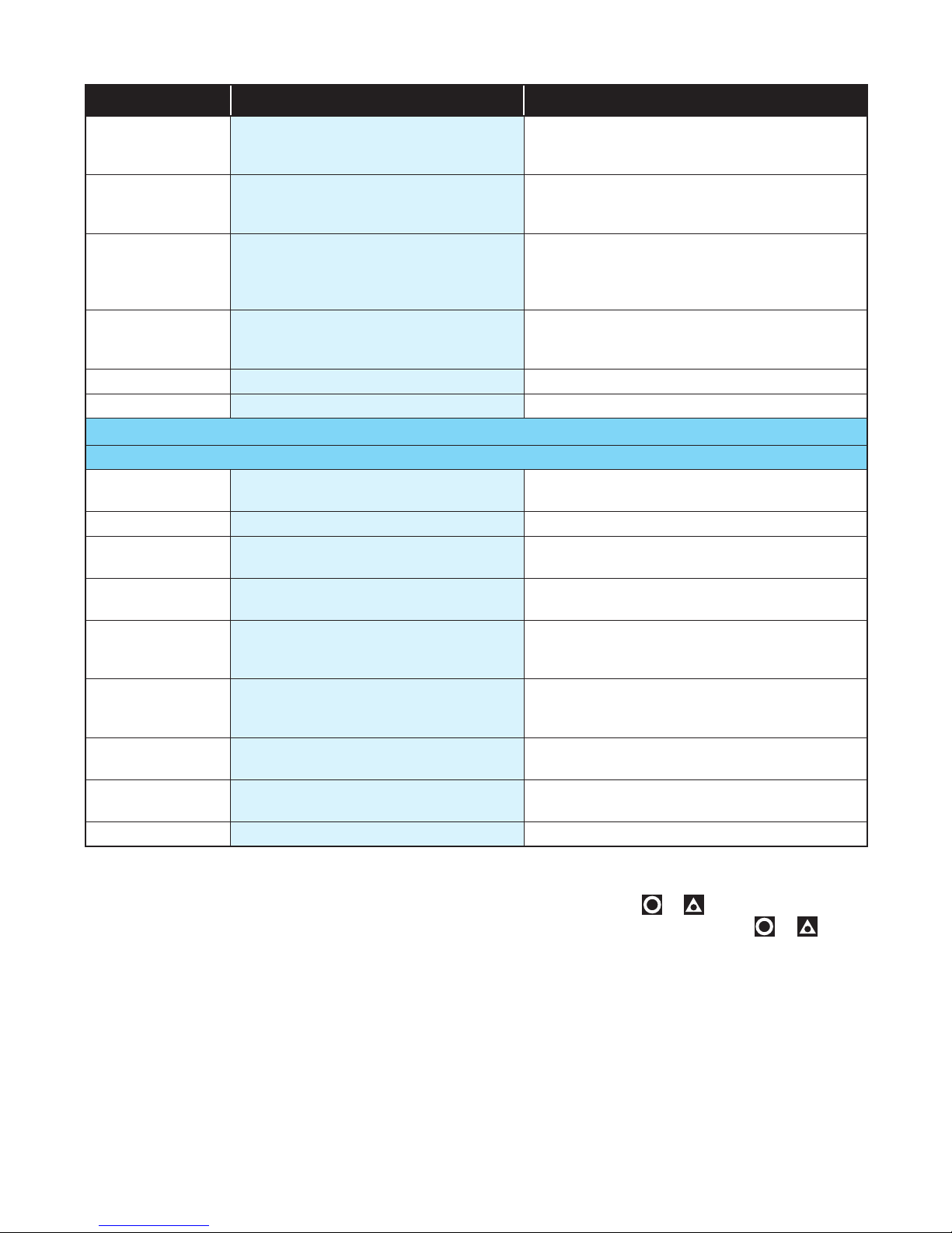
Parameter Name Description Meaning & Visibility
Input Type
-200 to 1200ºC
-328 to 2192ºF
-240 to 1373ºC
-400 to 2503ºF
-199 to 800ºC
-328 to 1472ºF
100 to 1824ºC 211 to 3315ºF B Thermocouple
0 to 2320ºC 32 to 4208ºF C Thermocouple
0 to 762ºC
32 to 1403ºF
0 to 1399ºC 32 to 2551ºF N Thermocouple
0 to 1795ºC 32 to 3198ºF R Thermocouple
0 to 1762ºC 32 to 3204ºF S Thermocouple
-240 to 400ºC
-400 to 752ºF
0 – 50mV** 0 – 50mV**
10 – 50mV 10 – 50mV
-128.8 to 537.7ºC
-199.9 to 999.9ºF
-128.8 to 537.7ºC
-199.9 to 999.9ºF
-128.8 to 537.7ºC
-199.9 to 999.9ºF
0.0 to 537.7ºC
32.0 to 999.9ºF
-128.8 to 400.0ºC
-199.9 to 752.0ºF
0 – 20mA 0 – 20mA
4 – 20mA 4 – 20mA
0 – 5V 0 – 5V
1 – 5V 1 – 5V
0 – 10V 0 – 10V
2 – 10V 2 – 10V
J Thermocouple
K Thermocouple
PT100
L Thermocouple
T Thermocouple
** 0 – 50mV is only linear dc input available on Extrusion models.
Input Units ˚C ˚F Select °C or °F temperature units – Default is °C
Units parameter hidden when linear input is used and units are not shown on the display
Input Decimal
Place
0000 00.00 Number of decimal resolution. (2 or 3 decimal
000.0 0.000
places only available.
13
Page 20
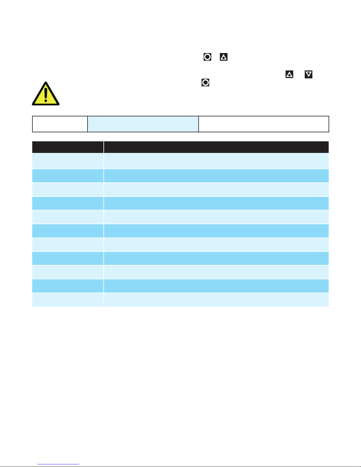
Parameter Name Description Meaning & Visibility
Scale Range Upper Limit
1000 Upper limit of scaled input range. (Only visible in
Setup Mode when a DC linear type is selected).
Default is input max.
Scale Range
Lower Limit
0 Lower limit of scaled input range. (Only visible in
Setup Mode when a DC linear type is selected).
Default is input min.
Input Digital I/P
Action
None None, Alarm Reset (clears latched alarms), Ctrl
Enable/Disable (disables control), Ctrl Auto/
Manual, Pre-Tune Start/Stop, Tune at SP Start/
Stop
Output 1 Usage Heat Heat, Cool, Non Linear Cooling (on Extrusion
model only), Alarm 1, Alarm 2, Alm. 1 or 2 (logical ‘OR’ of Alarm 1 & 2), Loop Alarm
Output 2 Usage Alarm 1 Same options as Output 1 Usage
Output 3 Usage Alarm 2 Same options as Output 1 Usage
If a Relay or SSR drive is fitted in Output 3 you will see >Output 3.
If the Linear option is fitted in Output 3 you will see the >Linear Output menus instead.
Linear Output
PV Retx Heat, Cool, PV Retx, SP Retx
Usage
Linear Output Type 0-10V 0-10V, 2-10V, 0-20mA, 4-20mA, 0-5V, 1-5V
Linear Output
Scale Range Max.
>Linear Output
Scale Range Min.
1373 Maximum PV or SP value corresponding to
maximum linear output for retransmission.
-240 Minimum PV or SP value corresponding to minimum linear output for retransmission.
Alarm 1 Adjust 1373 Sets the Alarm 1 value. (Range minimum to
range maximum) OFF disables the alarm. (Default alarm type is high alarm)
Alarm 2 Adjust -240 Sets the Alarm 1 value. (Range minimum to
range maximum) OFF disables the alarm. (Default alarm type is low alarm)
Setpoint Adjust 0 Target setpoint. Adjustable between setpoint
upper and lower limits Default is 0
Coms Unit
1 Modbus address from 1 to 255
Address
Coms Baud Rate 9600 1200, 2400, 4800, 9600, 19200 & 38400 bps
1. The Start Tune at SP function is not available for
Heat & Cool processes.
2. If the Input Type is changed, input scaling and
alarm values are set to new values based on the
maximum and minimum of the new input type. If
necessary, review these settings.
3. If necessary, press
& to clear the “Control is
Enabled” Pop Up Alert then press & to exit
the Setup mode.
14
Page 21
6 Advanced Configuration Mode
The Advanced Configuration mode gives access to all
the parameters accessible from the front panel; however, the device hides parameters that are not relevant
to your exact model code specification & configuration.
It may be faster to access some
parameters from the Setup Mode.
Lock Code 20
Menu Name Meaning & Visibility
User
Input Set up input sensor and range.
Calibration For entering calibration points.
Outputs Set functions for up to 3 outputs.
Control Control settings for PID, or ON/OFF control, and Auto-tune.
Provides access to User parameters including Control Enabled and Manual Control
Enabled parameters.
Press
Operator screen.
Enter Advanced Lock-code using & , then
press .
& to enter Advanced Configuration from
Lock code to enter Advanced Configuration
Mode. Default is 20.
Setpoint Setpoint and timer settings.
Alarm All alarm settings including sensor break alarm.
Comms Modbus address, baud rate and parity - only shown if RS485 option is fitted.
Display Lock code set up and Basic Setpoint Control enable/disable.
Operator Visibility setting for parameters that can be made visible in the User Mode.
Info
Revision level, Firmware version, Serial number and Manufactured date.
15
Page 22
7 User Mode
The normal, live screen showing the PV (process variable) or temperature is called the User Mode.
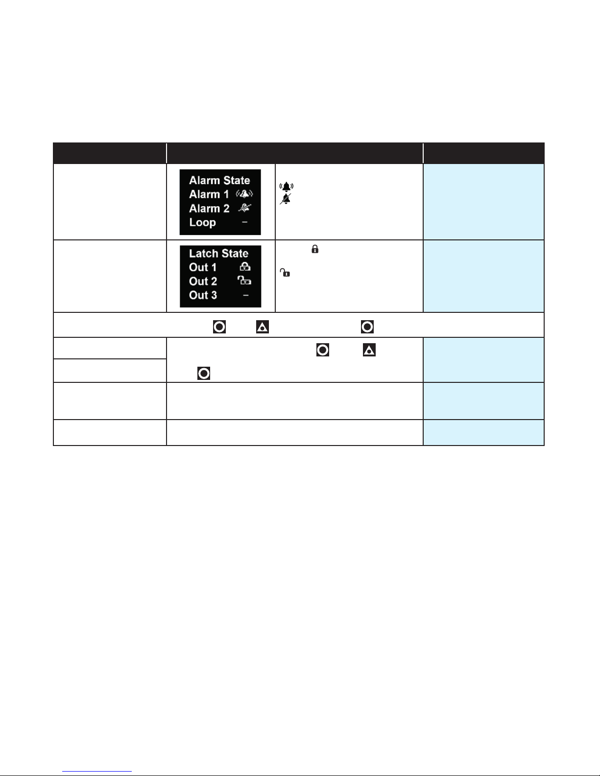
7.1 User Menu (Applicable to Standard and Extrusion Models)
Parameter Description Default Value
Alarm State
Alarm triggered
Alarm configured, but not
triggered
– Alarm not set
N/A
Latch State
To clear any latched outputs, press
Maximum PV
Minimum PV
Control Enable OFF - Control output(s) disabled. (Ignored when in man-
Manual Control Enable OFF - Automatic control, PID or On-Off control available.
To clear the stored value, press
Yes.
Press to accept.
ual mode).
ON - Control output(s) enabled.
ON - Manual control, Manual Power shown as P% xxx
then to select Yes. Press to accept.
Output Latched
Latch configured, but output
not Latched
– Latch not set
then to select
N/A
Screens show the
Maximum & Minimum PV
reached.
ON
OFF
16
Page 23
7.2 Input Menu (Applicable to Standard and Extrusion Models)
Parameter Description Default Value
Input Type Refer to Input types in the table in the Setup menu sec-
tion for a full list of inputs available.
Units Display Units either °C or °F.
This parameter is hidden when input is a linear type and
°C or °F are hidden from the display.
Units hidden when linear input is used and no unit is shown on the display
Decimal Place 0000
000.0
00.00 (not for temperature)
0.000 (not for temperature)
For temperature inputs, enter the maximum working
Scale Range Maximum
Scale Range Minimum
Filter Time
CJC Enable Enable Enables the internal thermocouple CJC (Cold Junc-
Digital I/P Action None
range. For linear inputs, enter the display value for the
maximum input level
For temperature inputs, enter the minimum working range.
For linear inputs, enter the display value for the minimum
input level.
Input filter time value to reduce noise. OFF or 0.5 to 100.0
seconds in 0.5 increments
tion Compensation). Disable Disables the internal CJC. If
disabled, external compensation must be provided.
Alarm Reset (clears latched alarms)
Ctrl Enable/Disable (disables control)
Ctrl Auto/Manual
Pre-Tune Start/Stop
Tune at SP Start/Stop
K thermocouple
°C
0000
Maximum allowed for
Input Type
Minimum allowed for
Input Type
2.0
Enable
None
The input scale range, consisting of
Scale Range Maximum & Scale Range
Minimum above, is used to narrow the
working range of the controller.
If the measured value is more than 5%
above or below the scaled range PV
display is replaced by HIGH (over-range)
or LOW (under-range).
The scale range also affects if Pre-Tune
will run. If the PV is <5% of the scaled
range from setpoint Pre-Tune cannot be
used.
17
Page 24
7.3 User Calibration Menu (Applicable to Standard and Extrusion Models)
Parameter Description Default Value
Offset Shifts the input value up or down by this offset value,
across the entire range.
Low Point Enter value at which the low point error was measured. Lower Limit
Low Offset Enter equal, but opposite offset value to the observed
low point error.
High Point Enter value at which the high point error was measured. Upper Limit
High Offset
Enter an equal, but opposite offset value to the observed
high point error.
0
0
0
7.4 Outputs Menu (Applicable to Standard and Extrusion Models)
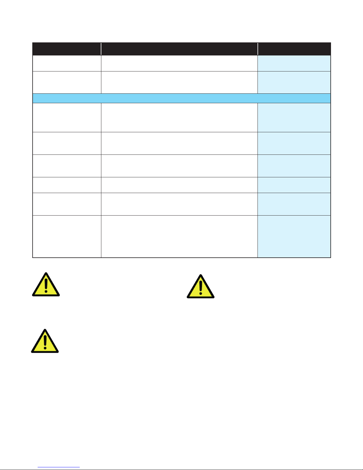
Parameter Description Default Value
Output 1 Sub-menu
Heat (Reverse acting control)
Cool (Direct acting control)
Non Linear Cooling (Extrusion model only)
Usage
Alarm Action
Latching
LED Indicator Direct - LED Indicator lit when output is active
Output 2 Sub-menu
Usage Same options as Output 1 - Usage Alarm 1
Alarm Action Same options as Output 1 - Alarm Action Direct
Latching Same options as Output 1 - Alarm Latching Off
LED Indicator Same options as Output 1 - LED Indicator Direct
Output 3 Sub-menu
If a Relay or SSR drive is fitted in Output 3, this sub-menu is visible.
Usage Same options as Output 1 Usage Alarm 2
Alarm Action Same options as Output 1 - Alarm Action Direct
Alarm Latching Same options as Output 1 - Alarm Latching Off
LED Indicator Same options as Output 1 - LED Indicator Direct
Alarm 1
Alarm 2
Alarm 1 or 2
(i.e. logical ‘OR’ of Alarm 1 & 2)
Loop Alarm
Direct - Output active when alarm triggers
Reverse - Output active when alarm is not triggered
Off - Alarm doesn’t latch
On – Alarm latches (remains in active state until cleared)
Reverse - LED Indicator lit when output is inactive
Heat
Direct
Off
Direct
18
Page 25
Parameter Description Default Value
Linear Output Sub-menu
If the Linear option is fitted in Output 3, this sub-menu is visible.
Heat (Reverse acting control)
Usage
Type
Scale Range Maximum
Scale Range Minimum
Retransmission of PV or SP: PV Retx, SP Retx
Display value at which retransmission output is at its
maximum value ( -1999 to 9999)
Display value at which retransmission output is at its
minimum value ( -1999 to 9999)
Cool (Direct acting control)
0-10V
2-10V
0-20mA
7.5 Control Menu (For Standard Model only)
Parameter Description Default Value
4-20mA
0-5V
1-5V
PV Retx
0-10V
1000
0
Proportion Heat Band The Proportional Bands for heating and cooling control,
Proportion Cool Band
Auto Reset (Integral) 0.01 to 99.59. and OFF (0.00) (minutes & seconds). 5.00
Overlap/Deadband In display units, range -20 to +20% of Heat & Cool Pro-
Differential (On/Off) Visible when using On-Off control.
Loop Alarm Time Visible when On/Off control & Loop Alarm assigned to an
Manual Reset (Bias) Manual Reset. Biasing of the control working point, 0 to
Heat Cycle Time 0.1 to 512.0 seconds
Cool Cycle Time 32.0
Output Interlock Prevents simultaneous activation of both heat & cool
Heat Power Limit % heating and cooling power upper limits
Cool Power Limit 100%
Power Up Action
Automatic Tuning
in display units. Set to ON/OFF (0) or PID control:
1 to 9999 - 0 decimal places
0.1 to 999.9 - 1 decimal place
0.01 to 99.99 - 2 decimal places
0.001 to 9.999 - 3 decimal places
Possible values/resolution depends on values display
resolution.
portional Band
In display units centred about the setpoint.
Range: 0.1% to 10.0% of input span
output.
Sets time before the loop alarm triggers.
(minutes & seconds)
100%. (-100% to 100% if heat/cool control)
Relay/SSR control output cycle times
outputs. Choose from On or Off.
Do not use if PB ‘overlap’ has been set
0 to 100%
Last - Powers up with control enable/disable in the same
state as on power off or power failure.
On - Always powers up with control enabled.
Off
Start Pre-Tune
Start Tune at SP
(Not available for Heat & Cool processes.)
161
161
0
8
99.59
25%
32.0
Off
100%
Last
Off
19
Page 26
7.6 Control Menu (For Extrusion Model only)
Parameter Description Default Value
Proportion Heat Band The Proportional Bands for heating and cooling control,
Proportion Cool Band
Auto Reset (Integral) 0.01 to 99.59. (minutes & seconds) and OFF (0.00). 5.00
Overlap/Deadband In display units, range -20 to +20% of Heat & Cool
Differential (On/Off) Visible when using On-Off control.
Loop Alarm Time Visible with On-Off control & Loop Alarm assigned to an
Manual Reset (Bias) Manual Reset. Biasing of the control working point, 0 to
Soft Start Time 0:01 to 60:00 or OFF (0:00) (hours & minutes) OFF
Soft Start Setpoint The setpoint used by the Soft Start.
Heat Cycle Time
Cool Cycle Time 32.0
Output Interlock
Heat Power Limit
Cool Power Limit 100%
Minimum Cooling
Impulse Length
Minimum Off Time
Non Linear Adjust
Power Up Action
Automatic Tuning
in display units. Set to ON/OFF (0) or PID control:
1 to 9999 - 0 decimal places
0.1 to 999.9 - 1 decimal place
0.01 to 99.99 - 2 decimal places
0.001 to 9.999 - 3 decimal places
Possible values/resolution depends on values display
resolution.
Proportional Band. -ve values=Deadband.
In display units centred about the setpoint.
Range: 0.1% to 10.0% of input span
output. Sets time before the loop alarm triggers.
(minutes & seconds)
100%. (-100% to 100% if heat/cool control)
See Soft Start function section.
0.1 to 512.0 seconds
Relay/SSR control output cycle times
Prevents simultaneous activation of both heat & cool
outputs. Choose from On or Off.
Do not use if PB ‘overlap’ has been set
% heating and cooling power upper limits, adjustable
from 0 to 100%
Sets the minimum temperature at which water cooling
will activate.
Non-linear cooling pulse time.
0.01 to 99.99 (seconds)
Minimum non-linear cooling pulse time.
0.01 to 99.99 (seconds)
Attenuates effective cooling vs PID cooling power.
From 1 to 999.9
Last - Powers up with control enable/disable in the same
state as at power off.
On - Always powers up with control enabled.
Off
Start Pre-Tune
Start Tune at SP (Not available for dual Heat & Cool)
161
161
0
8
99.59
25%
-240
32.0
Off
100%
120
10
20
5
Last
Off
20
Page 27

7.7 Setpoint Menu (For Standard Model only)
Parameter Description Default Value
Enabled - Enables the Delay and On Timers. Applies at
Enable Timer
Delayed Start Time
Ramp Rate
On Time
Upper Limit Used to limit the Maximum setpoint value. Scale Range Maximum
Lower Limit Used to limit Minimum setpoint value. Scale Range Minimum
Offset
next power-up or next control enable.
Disabled - Delay and On Timers are ignored.
(Setpoint ramping still functions.)
Time from power-up or control enable before control begins from 00.01 to 99.59 (hours & minutes) or OFF (0.00).
If delay is OFF control starts immediately.
Rate the actual setpoint changes from current PV to target setpoint following power-up or control enable.
From 0.001 to 9999 (Units / hr) or OFF (10000).
Any changes in the setpoint value also follow this rate.
The time the target setpoint will be maintained once
reached, from 00.01 to 99.59 (hours & minutes) or Off
(00.00)
Set to >99.59 for Infinite - control remains on indefinitely.
For use in multi-zone setpoint slave applications.
Offsets the setpoint from -1999 to 9999. Effective SP =
SP+Offset. NOTE: effective SP is not limited by setpoint
limits.
‘Offset in use’ pop-up appears when SP is changed.
Disabled
OFF
OFF
Infinite
0
7.8 Setpoint Menu (For Extrusion Model only)
Parameter Description Default Value
Rate the actual setpoint changes from current PV to tar-
Ramp Rate
Upper Limit Used to limit the Maximum setpoint value. Scale Range Maximum
Lower Limit Used to limit Minimum setpoint value. Scale Range Minimum
Offset
get setpoint following power-up or control enable.
From 0.001 to 9999 (Units / hr) or OFF (10000).
Any changes in the setpoint value also follow this rate.
For use in multi-zone setpoint slave applications.
Offsets the setpoint from -1999 to 9999. Effective SP =
SP+Offset. NOTE: effective SP is not limited by setpoint
limits.
‘Offset in use’ pop-up appears when SP is changed.
OFF
0
21
Page 28

7.9 Alarm Menu (Applicable to Standard and Extrusion Models)
Parameter Description Default Value
Alarm 1 Sub-menu
None
Type
Value Value for the alarm, from Range minimum to range maxi-
mum, or OFF (maximum +1). OFF disables the alarm.
Hysteresis Sets the alarm switching differential from 1 display unit to
the full input span.
Alarm 2 Sub-menu
Type
Value
Hysteresis
Options Sub-menu
Inhibiting of ‘active alarms’ at power-on, control enable
Alarm Inhibit
Alarm Notification
On - activates both alarms, if configured, when a sen-
Sensor Break Alarm
sor break is detected. If Off, alarms activate only break
condition is an alarm condition.
PV High
PV Low
Same options as Alarm 1 sub-menu.
or controller setpoint change.
None • Alarm 1 • Alarm 2
Alarm 1 & 2 (both alarms are inhibited)
Alternates ‘Alarm’ with PV value if selected alarm(s)
are active. Red alarm output LEDs are not affected
by this parameter.
None • Alarm 1 • Alarm 2
Alarm 1 and 2 (Alarm 1 OR 2)
Deviation
Band
PV High
1373
1
PV Low
-240
1
None
Alarm 1 and 2
Off
7.10 Communications Menu (Applicable to Standard and Extrusion Models)
Parameter Description Default Value
Unit Address Modbus address from 1 to 255 1
Baud Rate Coms data rate in kbps
1200, 2400, 4800, 9600, 19200 & 38400 bps.
Parity Parity checking: Odd, Even or None
9600
None
22
Page 29

7.11 Display Menu (Applicable to Standard and Extrusion Models)
Parameter Description Default Value
Setup Unlock Code
Advanced Unlock Code
Screen Timeout Screensaver time. Display turns off after 5, 15 or 30 mins.
Selected language
Transmitter
Reset to Defaults
View & adjust Setup lock code.
From 1 to 9999 or Off for no lock code
View & adjust Advanced lock code.
From 1 to 9999 or Off for no lock code.
Choose the display language (English plus one other).
From: English & German / English & French. The second
language offered can be changed via the configuration
software.
‘Enable’ hides the setpoint, SP.
Important: The device still functions as a controller even though the SP is hidden.
Used to reset all parameters back to the factory defaults, as shown on the right in
parameter lists.
See the Default Value column in the Setup and Advanced menu tables.
10
20
English
Disable
7.12 Operator Screens Menu (Applicable to Standard and Extrusion Models)
Parameter Description Default Value
Control Enabled
Manual Ctrl Enabled Hide
Alarm State Hide
Latch State Show
Maximum PV Hide
Minimum PV Hide
Remaining On Time
(Standard model only)
Remaining Delay Time
(Standard model only)
Hide or Show parameters in Operator Mode.
For security, or to simplify the operator screens, hide any
that you do not need to allow access to.
Hide
Hide
Hide
5
7.13 Information Menu (Applicable to Standard and Extrusion Models, Read Only menu)
Parameter Description
PRL
DOM
FW Version / FW Type Display of the units’ firmware version & code type numbers.
Serial Display of the Serial Number.
Out1
Out2
Out3
Comm
DI
The hardware/software revision level, used for internal quality control.
The Date of manufacture in mmyy format
Shows the outputs types fitted. These cannot be changed after manufacture.
Options are: –
SSR (SSR driver) or Relay
SSR (SSR driver) or Relay
None, SSR (SSR driver), Relay or Linear
Shows other options fitted. These cannot be changed after manufacture. Options
are: – RS485 communications - Fitted or None. Digital Input is isolated or not - Iso
or NonIs
7.14 Exiting the Advanced Configuration mode
If necessary, press & to clear any Pop-Up
Alerts.
Press & to move up one menu level. Some
menus have sub-menus so it may be necessary to
press this key combination more than once to exit.
23
Page 30

8 Calibration Mode
Low Process Value
Original Displayed Value
It is possible to calibrate the controller to compensate
for sensor errors and other tolerance errors in the system. This is achieved using the calibration mode. The
calibration mode allows an offset to be applied in one
of two ways. The method used will be dependent on
the process application.
These methods do not alter the internal
instrument calibration. Set the offset
values back to zero to restore standard
measured values. Re-calibration of the
internal base calibration is also possible,
but should only be attempted by qualified
personnel as it overwrites the factory
calibration – see Base Input Calibration
below.
8.1 Single Point Calibration (PV Offset)
This is a ‘zero offset’ applied to the process variable
across the entire span. Positive values are added to the
reading, negative values are subtracted. It can be used
if the error is constant across the range, or the user
is only interested in a single critical value. To use, select Single Point Calibration from the input calibration
menu, and simply enter a value equal, but opposite to
the observed error to correct the reading.
This example shows a positive offset value.
8.2 Two Point Calibration
This method is used where an error is not constant
across the range to change the calibration slop. Separate offsets are applied at two points in the range to
eliminate both “zero” and “span” errors.
1. Measure and record the error at a low point in the
process.
2. Measure and record the error at a high point in the
process.
3. Go to the first two-point input calibration screen.
a. Enter the desired low point value as the Calibra-
tion Low PV value.
b. Enter an equal, but opposite value to the ob-
served error as the Calibration Low Offset to correct the error at the low point.
4. Go to the second two-point input calibration screen.
a. Enter the desired high point as the Calibration
High PV value.
b. Enter an equal, but opposite value to the ob-
served error as the Calibration High Offset to
correct the error at the high point.
Calibration High Offset
Single Point ‘Offset
Calibration’ value
New Displayed Value
Original Displayed Value
For example: If the process displays 27.8 when it
should read 30, The error is -2.2 so an applied offset
of +2.2 would change the displayed value to 30. The
same offset is applied to all values, so at 100.0 the new
displayed value would be 102.2.
New Displayed Value
Calibration Low Offset
Calibration
Choose values as near as possible to the bottom and top of your usable span to achieve
maximum calibration accuracy. The effect of
any error can grow at values beyond the chosen calibration points.
The single and two-point calibration methods can be
used together, if you need to change the calibration
slope and offset the zero point simultaneously.
Calibration High
Process Value
24
Page 31

8.3 Base Input Calibration
Calibration of the input is carried out during manufacture, and for most applications, re-calibration is not
required during the lifetime of the instrument. User
1-point and 2-point calibration can be carried from the
User Calibration menu.
Re-calibration of the internal base values
is possible, but should only be attempted
by qualified personnel as it overwrites
the factory calibration.
A suitable calibration signal source is required for each
input type. To verify the accuracy of the instrument or
carry out re-calibration, the input sources listed below
are required, with better than ±0.05% of the reading
accuracy:
1. DC linear inputs: 0 to 50mV dc, 0 to 10V dc & 0 to
20mA dc.
2. Thermocouple inputs - complete with 0ºC reference
facility, appropriate thermocouple functions and
compensating leads (or equivalent).
3. RTD inputs: decade resistance box with connections for three-wire input (or equivalent).
8.5 Base Calibration Procedure
Input calibration is carried out in five phases as shown
below, each phase corresponds to an input range of
the instrument.
The 50mV phase must be calibrated first before any other range(s).
Calibration phases:
i. mV for 50 mV
ii. V for 10 V
iii. mA for 20 mA
iv. RTD input (200Ω ohm resistance source)
v. CJC (K type thermocouple source at 0ºC required)
For Extrusion models phase ii and iii (V & mA) are omitted.
8.6 Calibrating the mV Input
1. Check your calibration source is connected to the
correct terminals on the 1020 Rail. For 50mV, connect your mV source +ve to pin 14 and -ve to pin 15
located on the bottom rear connector – see wiring
section.
8.4 Calibration Check
1. Set up the instrument to the required input type.
2. Note down, then remove any single or two-point
calibration values by setting them to zero.
3. Power up the instrument and connect the correct
input leads, to the correct terminals.
4. Leave powered up for at least five minutes for RTD
and DC linear inputs, or at least 30 minutes for thermocouple inputs.
5. After the appropriate delay for stabilization has
elapsed, check the calibration by connecting the
appropriate input source and checking a small
number of cardinal points.
6. Repeat the test for all required input types.
7. Check the results against the specification stated
for the required input type.
8. Reinstate the calibration values removed at step if
they are still appropriate.
Make the connections using the correct thermocouple cable type. For all other input types
use copper cable. Using the wrong type of cable will cause incorrect readings. This is especially important with thermocouple sensors.
2. Press and hold the button, whilst the instrument
is powering up, until the display shows the screen
starting with mV. Be patient, may take approximately 30 seconds.
3. In the calibration phase menu displayed, highlight
mV from the list.
4. With mV selected, press . The following screen
will appear:
>mV Input
userCAL
Press enter
to start
5. Press . You should see the messages Starting
Calibration, followed by Calibration in Progress.
A dot moves across the display to show the progress.
6. If the input is wrongly connected or an incorrect signal is applied the calibration will be aborted and the
display will show Calibration FAIL. The previous
calibration value will be retained.
25
Page 32

7. If the calibration was successful, the display shows
Calibration PASS.
8. To clear the Pass or Fail pop-up press and .
9. Now press and to return to the calibration menu.
From here either select another calibration phase,
or press & again to return to the operator
screen.
When you have completed the required phases, press
& to exit back to the operator screen.
The Calibration Mode automatically exits if there is no
button activity for five minutes.
8.8 Calibration Input States
8.7 Calibrating Other Input Types
The 50mV calibration must be carried out first. After
this, you can select the other types in turn. The other calibration phase procedures are similar to the mV
phase above, but ensure that the correct input signal
and connections are used – see the wiring section for
connection details.
Note: When calibrating the RTD input type, connect an
accurate 200Ω resistance source across pin 14 and pin
15, and link between pin 13 and pin 14 to replicate the
3-wire compensating lead.
8.10 Calibration Modbus Addresses
Each input can have one of three states:
Description State Shown
Input not calibrated noCAL
Factory calibrated factCAL
User calibrated userCAL
8.9 Calibration Progress
Description Popup
Initial popup Starting calibration
During calibration Calibration in progress
Calibration succeeded Calibration PASS
Calibration failed Calibration FAIL
The following Modbus addresses can be used to initiate the calibration phases and read back the status.
Description Comment Dec Hex
50mV Calibration
10V Calibration
20mA Calibration
RTD Calibration
CJC Calibration
Calibration Status
Write 0xCAFE to start the
calibration for the selected input.
0x0000 - Calibration Failed
0xCAFE - Calibration Busy
0xFFFF - Calibration Successful
Write Only
Read Only
1700
1701
1702
1703
1704
1770
6A4
6A5
6A6
6A7
6A8
6EA
26
Page 33

9 Automatic Tuning
To avoid process time-lags that can make effective
tuning difficult or even impossible, ensure correct sensor and heat source positioning in your application before use.
There are two automatic tuning methods on the 1020
and 1030 controllers. Pre-Tune and Tune at SP.
The Pre-Tune is a ‘start-up disturbance’ tuning method. It usually gives better results than Tune at SP.
However, a minimum 5% of span distance between
the process value and setpoint is required for Pre-Tune
to run. This means it cannot be used if the setpoint is
close to ambient temperature. In this case, use Tune at
SP. A full description of Pre-tune and Tune at SP is in
the Glossary.
Refer to the Warnings & Messages
section for information on the Tuning
Error messages.
9.1 Running the Pre-Tune
1. For best results, before running the Pre-Tune adjust
the input span (Scale Range Maximum and Scale
Range Minimum) to suit your process, allowing a
small tolerance beyond the operating range. e.g. if
operating from ambient to 180°C, perhaps set the
range 0 to 200.
2. Run from cool. Ideally the process should to be cool
before running Pre-Tune. Disable control, or temporarily lower the setpoint, until the PV is a least 5%
of the input span difference between the current SP
and PV. A larger gap is better if this is possible.
3. Allow for overshoot and undershoot. Please be
aware that when the Pre-Tune is run, full power
is applied to the process for some time. Although
the controller cuts power before the setpoint is
reached, some process over/undershoot should be
expected. The overshoot might exceed the setpoint
value. If exceeding SP might cause a problem, run
your first Pre-Tune with a lower SP. If required and
safe to do so, you can run another Pre-Tune closer
to the required SP.
4. The Pre-Tune can be activated via the Automatic
Tuning parameter in the Setup menu or the Advanced Configuration menu. It may also be activated via a Modbus command.
The message ‘TUNE’ is displayed whilst Pre-Tune is
running.
Pre-Tune will not engage, and a Tune Error message
will be displayed under the following conditions: 1)
There is a sensor break, 2) The PV is <5% of span
from SP, 3) A setpoint ramp has been set, 4) A Timer
is running, 5) The current control mode is On-OFF
6). The controller is in Manual mode. 7) Control is
Disabled*. Resolve the displayed problem then run
Tune at SP again if required. *Note: If control is disabled, running Pre-Tune at First Power-up (or immediately after a Reset to Default) automatically sets
the control to enabled.
5. Once Pre-Tune is complete it will disengage, and
the ‘TUNE’ notification ends. The length of time the
tuning takes to complete will vary from process to
process.
9.2 Running Tune at SP
1. Initial PID values. Tune at SP needs a reasonable
level of process stability to run. It is therefore recommended to set the initial PID values in the Control menu back to their default values: Proportional
Band to 10% of your chosen input range, Auto Reset (Integral) to 5.00 and Rate (Derivative) to 1.15
before using Tune at SP.
2. The Tune at SP can be activated via the Automatic
Tuning parameter in the Setup menu or the Advanced Configuration menu. It may also be activated via a Modbus command.
The message ‘TUNE’ is displayed whilst Tune at SP
is running.
3. Once Tune at SP is complete it will disengage, and
the ‘TUNE’ notification ends. The length of time the
tuning takes to complete will vary from process to
process
9.3 Tuning at SP Troubleshooting
Tune at SP will not engage, and a Tune Error message
will be displayed under the following conditions: 1)
There is a sensor break, 2) A setpoint ramp has been
set, 3) A Timer is running, 4) Control is Disabled. 5) The
current control mode is On-OFF 6) The controller is in
Manual mode.
Resolve the displayed problem then run Tune at SP
again if required.
If Tune at SP starts, but remains running indefinitely,
the cause is either the process value not achieving reasonable stability (±1% of span), or the control power
variation is too great (±10%).
To resolve this:
1. Check the PID values in the control menu were at
the defaults values (see above). If they were correct,
go to step 2. Otherwise, correct them and run Tune
at SP again.
2. If step 1 has not resolved the issue, observe the
displayed process value for >5minutes and noting
the highest and lowest values seen. Subtract the
lowest value from the highest to find the peak-to-
27
Page 34

peak deviation. Check the input span (Scale Range
Maximum minus the Scale Range Minimum) to see
if the it is >100 x the peak-to-peak deviation. If not,
increase the input span to more than this value, and
run Tune at SP again.
3. If this has not resolved the issue, double the current
PID terms (Proportional Band, Auto Reset and
Rate values), then run Tune at SP again.
4. In the unlikely event that the tuning still does not
complete continue from step 3.
9.4 Tuning at SP for Heat and Cool
Tuning at SP is possible for Heating or Cooling applications, but not for both Heat and Cool together. If you
have defined outputs for heating and cooling, Tune at
SP is not offered in the tuning menu. Instead use PreTune.
28
Page 35

10 Digital Input Operation
Depending on your model, the digital input can be used
to perform one of the available functions as shown in
the table below.
High = Open contacts (and 2 to 24Vdc for the isolated
digital input).
Low = Closed contacts (and <0.8Vdc for the isolated
digital input).
Digital Input
Controller
Functions
Reset Latched Alarm(s) No Action Reset*
Control Enable/Disable Disable Enable
Auto/Manual Manual Automatic
Pre-Tune Start/Stop Stop Start*
Tune at SP Start/Stop Stop Start*
*Alarm outputs only reset if the alarm condition is nolonger present and tuning will only start if the settings
and current process conditions allow (see tuning section for more details)
Limiter
Function
Reset Latched Limit &
Alarm(s)
*Limit and Alarm outputs only reset if the limit exceed
and/or alarm conditions are no longer present.
State Transition
High to
Low
Digital Input State
Transition
High to
Low
No Action Reset*
Low to
High
Low to
High
When the instrument is turned on, a change in the digital input signal from High Low, or Low to High will
cause the function to change (unless it is already in the
state dictated by the signal change).
The keypad can also be used to change the status of
the same function via the relevant menu. The most
recent digital input or keypad instruction will be
implemented.
The digital input is “edge sensitive”, which
means that it only reacts to a detected
transition in the input state. The device
cannot detect a status change made
when it is turned off. It also means that
if it is in the “ON” state, but the current
condition of the unit is the “OFF” state
(either because a keypad instruction or
it has powered up that way) the digital
input would first have to be set first to
OFF and then ON again before it would
set the function ON.
However, on the Limiter model if the Digital Input is in
an “ON” state at power-up it gives a Reset signal. Once
powered up the Limiter model behaves the same way
to a transition.
29
Page 36

Below is an illustration of digital input and keypad use. The example is for the Control Enable function. Other functions behave in a similar way.
Unit
Start-Up
Control Function
Control Enabled
Control Disabled
Digital Input
Signal High
Signal Low
HMI
Menu – “ON”
Menu – “OFF”
1. On start-up, the unit uses the Power-Up Action for
its initial control state. In this example, it starts in the
disabled condition.
2. Digital input signal changes from Low to High;
therefore, control becomes enabled. The Control
Enable parameter will say ON, when viewed from
the HMI (front panel).
3. The keypad on the HMI (front panel) menu is used
to change the control back to disabled, Control En-
able parameter = OFF.
4. The digital input changes state, going from High
to Low, but as the control is already disabled no
change is made.
5. Then the digital input goes from Low to High again,
re-enabling the control. The Control Enable parameter in the HMI also shows control is ON again.
30
Page 37

11 Timer Feature
11.1 Timer Feature
The timer feature is only available on the Standard
model. It consists of a Delay Timer and an On Timer.
When the Timer Enable parameter is set to Disabled
the timer will not be used and the delayed start time
and on time are ignored. Note: If the setpoint has been
set to ramp, this will still be active, even if the timer is
Disabled.
The timer, control power down state and the power-up action have the following relationship:
When Enabled the timer will take control of the Setpoint as defined by the Delayed Start Time and On
Time parameters. Enabling the timer has no effect until
the controller is power cycled or the control is disabled
then re-enabled.
Power-up
Control state
at power down
Enabled Last Disabled N/A Control Enabled
Disabled Last Disabled N/A Control Disabled
Enabled On Disabled N/A Control Enabled
Disabled On Disabled N/A Control Enabled
Enabled Last Enabled Off Control Enabled
Disabled Last Enabled Off Control Disabled
Enabled On Enabled Off Control Enabled
Disabled On Enabled Off Control Enabled
Enabled Last Enabled Time Set Control Disabled until Delay timer expires
Disabled Last Enabled Time Set Control Disabled
Enabled On Enabled Time Set Control Disabled until Delay timer expires
Disabled On Enabled Time Set Control Disabled until Delay timer expires
Action
setting
Timer Enable
parameter
setting
Delayed
Start Value Control state at power-up
11.2 Delay, Ramp & Timer Diagram
The delay, ramp and soak is only available on the standard model.
1. From power-up, if control is in the enabled state, or
whenever control is changed from disabled to enabled, the unit delays process control (i.e. control is
still disabled) until the Delay Timer expires (time as
set by Delayed Start Time). If this is OFF, step 1 is
omitted.
2. Setpoint ramps from the current PV to the target
setpoint at Ramp Rate (‘RAMP’ alternating with the
current effective SP value indicates it is still ramping). If Ramp Rate is OFF the effective setpoint
steps directly to target setpoint.
3. After any Delay and/or Ramp completes, the setpoint ‘Dwells’ at the target value while the On-Timer
counts down (time set by On Time).
4. When the On Timer finishes the control switches off
(i.e. control is disabled). If the On Timer has been
set to OFF, step 4 is omitted, and control is maintained at the setpoint indefinitely.
31
Page 38

12 Extrusion Model Only Features
12.1 Non-Linear Cooling Function
The initial cooling effect with water cooling can be
very strong when water first flows into a hot process.
Evaporation extracts significant amounts of heat energy making the effective cooling power disproportionally high at nominally low levels of cooling output.
This makes process control more difficult, particularly
if “over-cooling” during the transition from heating to
cooling causes the heating to be reactivated. Non-Linear Cooling can be used to counteract these effects by
applying the cooling more gradually at first.
To enable the Non-Linear Cooling function the Output
1, Output 2 or Output 3 Usage parameter needs to be
set to Non Linear Cooling.
Heat Power
Cool Power
>Output 1
Usage
This table lists the Control sub-menu parameters related to non-linear cooling.
Title Description
Minimum
Cooling
Impulse
Length
Minimum Off
Time
Non-Linear
Adjust
Non Linear Cooling
Alarm 1
Alarm 2 Alarm 1 or 2
Loop Alarm
The minimum temperature for nonlinear cooling to operate
The fixed “On” pulse duration with
non-linear cooling
The minimum “Off” duration with
non-linear cooling
Adaptation of characteristics of the
non-linear cooling
Heat Power
12.2 Method
The cooling characteristic is altered so that the controller output is weak until approximately 70% of nominal
cooling demand. Beyond this level, the correcting variable rapidly rises to the maximum cooling allowed.
Cooling is inhibited entirely until the Minimum Cooling temperature has been exceeded. After that it turns
ON with fixed duration pulses (adjustable with Impulse
Length parameter). The OFF time between pulses is
varied to adjust the cooling effort, but is never off for
less than Minimum Off Time value whenever cooling is
active. This ratio limits the maximum effective cooling.
The maximum effective cooling is calculated as follows:
Impulse Length
Max Cooling= x 100%
Impulse Length + Minimum Off Time
The Non-Linear Adjust parameter can be reduced if the
corrective action is too severe by reducing the non-linearity of the effective output. See the examples below.
32
Page 39

Non Linear Adjust = 900
Non Linear Adjust = 1
33
Page 40

12.3 Parameter Adjustment
Minimum Cooling
Cooling is enabled only above the temperature set because evaporation, with its associated cooling effect,
is not possible at temperatures below 100°C. Set this
>100, but it should be well below the normal operating
setpoint.
Note: In manual mode cooling is still possible below
this temperature.
Impulse Length
A fixed length for cooling pulses set by this parameter.
The ON pulses are this length for all cooling output values above 1% nominal cooling demand.
Relatively low values should be used, but remember that
the ratio of the Minimum Off Time vs Impulse Length
affects the maximum effective cooling (see above). Do
not allow this to limit cooling to the extent that insufficient cooling effect is available for the process.
The impulse length is also limited by the hardware (e.g.
the response time of your valve). Valves and electromechanical relays should not be switched to quickly.
Consult the device manual or check with your supplier
for suitable minimum settings.
Using these settings, and observe the transition
from heating to cooling. If there is a noticeable
over-reaction, where the cooling is still too strong,
increase the Non-Linear Adjust value until the effect is reduced to acceptable levels. If the transition
becomes too slow, with effective cooling unacceptably delayed, reduce the value set.
12.4 Soft Start Function
Soft Start is primarily intended to allow heaters to dry
out gradually at start-up condensation which can form
when the heaters are cold can cause damage if it evaporates too quickly.
Soft Start has its own setpoint, allowing a pre-defined
low-temperature dwell period which reduces the power
demand from the heaters, allowing moisture to evaporate more slowly before going to full working temperature. During this period, it also minimizes the heater-on
times by reducing the cycle time and limiting the PID
power demand.
Note: Soft Start does not limit the instantaneous current to the heaters when the output is on.
Activated by setting the parameters Soft Start Time
and Soft Start Setpoint.
Minimum Off Time
The “off” time between pulses is varied dependent
upon the PID cooling demand. The Minimum Off Time
is the minimum allowed “off” time (but note that below
1% of cooling demand, the output is disabled).
The time set is hardware-dependent (e.g. the response
time of your valve). Generally, it is best set to the lowest
value compatible with the output switching device, but
remember that valves and electromechanical relays
should not be switched to quickly. Consult the device
manual or check with your supplier for suitable minimum settings.
Remember that the ratio of the Minimum Off Time vs
Impulse Length affects the maximum effective cooling
(see above). Do not allow this to limit cooling to the
extent that insufficient cooling effect is available for the
process.
Non-Linear Adjust
This attenuates the cooling curve, and altering where
the output rate begins to increase more rapidly. The value can be reduced if the corrective action is too severe,
this reduces the non-linearity of the effective output.
To find an appropriate Non-Linear Adjust setting:
First set Minimum Cooling, Impulse Length and
Minimum Off Time to appropriate values (see
above), and initially set Non-Linear Adjust to 5. Use
Pre-Tune or manual tuning to adjust the controllers
PID settings to your process.
1. When powered up the unit will control to the Soft
Start Setpoint. The control cycle time is 1/4 of the
value entered (subject to the minimum possible
value of 0.5s) and the maximum power demand is
limited to the Heat Power Limit value (set in the
Control menu). The reduced cycle time is used during the soft start phase.
2. After reaching the Soft Start Setpoint the Soft Start
Time begins. The timer starts as soon as the PV is
equal to Soft Start Setpoint – 1. The Soft Start Setpoint is maintained until this time has elapsed.
3. When Soft Start Timer expires, the unit returns
to normal operation. It controls to the normal setpoint, the cycle time reverts to the value set and the
Heat Power Limit is no longer used.
Remember, when using the Soft Start
feature the Heat Power Limit is only
active from power-on and during the Soft
Start Time. It remains in use until the Soft
Start timer expires or all the time if no
Soft Start time is OFF.
34
Page 41

12.5 Extrusion Only Parameters in the Control menu
Soft Start Parameters
Non-Linear Cooling parameters
35
Page 42

13 Limiter Models
13.1 Introduction to the Limiter
Model
LM EX AL
The Limiter model has fixed output functions.
Depending upon which option is fitted in Output 3 it is
Alarm 2 or Retransmit PV.
Refer to the Information menu or check the product
label identify your version.
Output 1. = Limit
Output 2. = Alarm 1
Output 3. If Relay or SSR = Alarm 2 / If Linear = Re-
transmit PV
The Limiter LEDs have fixed functions: Limit, Exceed
& Alarm.
When the PV enters the Exceed condition both the Limit and Exceed LEDs turn ON. Going from the Exceed
condition back into the Safe condition the Exceed LED
will turn off but the Limit LED will stay latched until it
is reset. Remember the Limit output itself is energized
in Safe condition but de-energizes when in the Limit
condition.
Navigating is the same as the Standard and Extrusion
versions, see General Navigation & Editing, but for security, users cannot change parameter values such as
the Limit Setpoint in the Operator mode on the Limiter
model. These can only change values via the lock code
protected Setup or Advanced Configuration modes.
Warning & Error messages on the Limiter model are
similar to the Standard and Extrusion versions, with
the exclusion of control or tuning related messages. On
the Limiter, there is the additional pop-up alert Limit
Exceeded message if the process is beyond the limit
value set.
Please refer to the Warnings & Messages section.
The Annunciator alarm type, which can be selected for
Alarm 1 or Alarm 2, cannot be inhibited.
13.2 Limiter Modbus Communica-
tions
Please refer to the Commonly Used Modbus Addresses and the Limiter Modbus Addresses for the Modbus
register addresses.
See the Serial Communications for general communications information.
13.3 Limiter Digital Input
The Digital Input has only one function on the Limiter
model. There is no need for a configuration parameter
because it is always a Limit & Alarm Reset. Refer to the
Digital Input Operation section. However, in addition on
the Limiter model, if the Digital Input is in an Open state
at power-up it gives a Reset signal.
36
Page 43

13.4 Limiter Operator Mode & Screens
User Screen PV – top
Temperature & Unit – centre & right.
LIM & Limit Setpoint - bottom
IMPORTANT: Visibility for parameters below must be set to Show in the Operator menu.
Alarm State
Alarm triggered
Alarm configured, but not triggered
– Alarm not set
Latch State
Maximum PV
Screens show the Maximum & Minimum PV reached.
Minimum PV
13.5 Limiter Output Latching
When an SSR drive or Relay output is configured to
‘latch’ it will remain on after the limit or alarm condition has cleared. The latch enable parameter, Output
Latching, needs to be ON for outputs you want to
latch.
Limiter Clearing Latched Outputs
The latch condition, shown by in the Latch State
screen, needs to be cleared either via a Modbus command, digital input or from the front panel.
To clear latches from the front panel, in the Latch State
screen, press then to select Yes.
Press to accept.
Limiter Start-up Latch
The parameter Startup Latch, is only present on the
limiter model. It determines how latching outputs behave when the unit is powered up. It is set individually
for each of the outputs (limit and/or the 2 alarms). The
three possible modes are as follows:
• Reset Latch: The latch state is not remembered
when the unit is powered off. The latch becomes
active again only if the associated limit / alarm state
is present at or after power-on.
Output Latched
Latch set, but output
not Latched
– Latch not set
• Always Latch: The instrument will always power on
with the chosen output in the latched state, even if
the associated limit or alarm is not active.
• Last Latch: The latch state is remembered on
power down. Any output that was latched on power
down it will still be latched when power is restored,
even if that limit or alarm is no longer active.
Note: If a limit or alarm state exists at power-up,
previously unlatched outputs always activate immediately, no matter how the Start-up Latch has
been set.
Limiter Sensor Break Detection
If a “Sensor break” is detected on the Limiter model,
this always triggers the Limit exceed condition, place
the process into a safe state. Correct the input problem, then unlatch the limit output to resolve this.
Limiter Output 3 – Linear, Relay or SSR drive
• If the linear output is fitted to Output 3 on the Limiter
model, it can only be used for a PV re-transmit function.
• If a relay or SSR drive is fitted in Output 3 then it is
fixed as Alarm 2.
To clear press
to select Yes.
Press to accept.
To clear press
to select Yes.
Press to accept.
then
then
37
Page 44

13.6 Limiter Setup Mode Parameters
If necessary, press & to enter Setup from Operator mode.
Enter Setup Lock-code (default of 10) using and
, then press .
The parameters are shown in the following table
Parameter Description Default Value
* Maximum of 1 decimal place for temperature inputs, in the blue square.
J Thermocouple *
-200 to 1200ºC
-328 to 2192ºF
K Thermocouple *
-240 to 1373ºC
-400 to 2503ºF
-199 to 800ºC
-328 to 1472ºF
B Thermocouple
100 to 1824ºC 211 to 3315ºF
C Thermocouple
0 to 2320ºC 32 to 4208ºF
L Thermocouple *
>Input Type
> Input Units °C or °F (not available for Linear dc inputs)
>Input
Decimal Place
Scale Range maximum & minimum are only visible when input is a linear dc type.
0000 – no decimal point
000.0 – one decimal point
00.00 – two decimal points (linear dc only)
0.000 – three decimal points (linear dc only)
0 to 762ºC
32 to 1403ºF
N Thermocouple
0 to 1399ºC 32 to 2551ºF
R Thermocouple
0 to 1795ºC 32 to 3198ºF
S Thermocouple
0 to 1762ºC 32 to 3204ºF
T Thermocouple *
240 to 400ºC
-400 to 752ºF
Linear dc
0 – 20mA
0 – 50mV
0 – 5V
0 – 10V
1. Some parameters may be hidden depending upon
configuration & hardware.
2.
Note the permissible ranges for each temperature
sensor type, below. For example, the B type thermocouple readings cannot have a decimal point, and it
cannot measure below 100ºC or above 1824ºC.
3. The number of decimal points is set by the Decimal
Place parameter.
-128.8 to 537.7ºC
-199.9 to 999.9ºF
-128.8 to 537.7ºC
-199.9 to 999.9ºF
PT100 *
-128.8 to 537.7ºC
-199.9 to 999.9ºF
0.0 to 537.7ºC
32.0 to 999.9ºF
-128.8 to 400.0ºC
-199.9 to 752.0ºF
4 – 20mA
10 – 50mV
1 – 5V
2 – 10V
K Thermocouple
˚C
0000
38
Page 45

Parameter Description Default Value
>Input Scale Range
Maximum
>Input Scale Range
Minimum
>Limit Type
>Limit Value
> PV Retrans Type
>PV Retrans Scale
Range Maximum
> PV Retrans Scale
Range Minimum
>Alarm 1 Value
>Alarm 2 Value
The scaling value for the input range maximum.
The scaling value for the input range minimum.
High – device will limit when PV is greater than the Limit
value. (Exceed condition if PV>Limit Value).
Low - device will limit when PV is less than the Limit value.
(Exceed condition if PV<Limit value).
The exceed condition value at which the Limit output will
trip.
PV Retrans parameters are only visible if Output 3 is Linear.
0-10V
2-10V
0-20mA
4-20mA
0-5V
1-5V
Displayed PV value corresponding to maximum linear
output.
Displayed PV value corresponding to minimum linear output.
Range minimum to range maximum,
or OFF (maximum +1) where OFF disables alarm.
Default alarm type is PV High.
If a Relay or SSR drive is fitted in Output 3 you will see Alarm 2.
Same options as Alarm 1.
Default alarm type is PV Low.
1000
0
High
-240
0-10V
1373
-240
1373
-240
>Coms Unit Address
>Coms Baud Rate
Modbus address from 1 to 255
1200, 2400, 4800, 9600, 19200 & 38400
>Coms Parity Odd, Even or None
If the Input Type is changed the relevant
values from the table above are used for
the Scale Range Maximum and Scale
Range Minimum. Review and change if
required.
1
9600
None
If necessary, press & to clear any Pop Up Alerts.
Press & to exit the Setup mode.
39
Page 46

13.7 Limiter Advanced Configuration Parameters
Sub-menu Name
1. Input
2. User Calibration
3. Outputs
4. Communication
5. Display
6. Information
If necessary, press
figuration mode from Operator mode.
Enter Advanced Lock-code (default of 20) using
and , then press .
13.8 Limiter - Input Menu
Parameter Description Default Value
Input Type
Units Display Units either °C or °F.
Decimal Place 0000
Scale Range Maximum The scaling value for the input range maximum.
Scale Range Minimum The scaling value for the input range minimum.
Filter Time OFF or 0.5 to 100.0 seconds in 0.5 increments
CJC Enable Enable – Enables the internal thermocouple CJC (Cold
Possible Input types are as listed in the
Limiter Setup mode parameters above
This parameter is hidden when input is a linear type and
°C or °F are hidden from the display.
000.0
00.00 (not for temperature)
0.000 (not for temperature)
Junction Compensation).
Disable – Disables the internal CJC.
External compensation must be provided for thermocouples.
& to enter Advanced Con-
K thermocouple
°C
0000
Maximum allowed for
Input Type.
Minimum allowed for
Input Type.
2.0
Enable
The input scale range, consisting of Scale
Range Maximum & Scale Range Minimum
above, is used to narrow the working
range (input span) of the controller
At 5% beyond the scaled range the controller with give
over-range or under-range warnings.
For example, a range 0 to 100 gives a span of 100c, so
when the PV is >105c the display will show HIGH.
13.9 Limiter - User Calibration Menu
Parameter Description Default Value
Offset
Low Point Enter value at which the low point error was measured.
Low Offset
High Point Enter value at which the high point error was measured.
High Offset
Shifts the input value up or down by a single offset
amount across the entire range.
Enter equal, but opposite offset value to the observed
low point error.
Enter an equal, but opposite offset value to the observed
high point error.
40
0
Lower Limit
0
Upper Limit
0
Page 47

13.10 Limiter - Outputs Menu
Parameter Description Default Value
Limit Output
High – device will limit when PV is greater than the Limit
Type
value. (Exceed condition if PV>Limit Value).
Low - device will limit when PV is less than the Limit
value. (Exceed condition if PV<Limit value).
High
Value
Output Latching
Startup latch
Alarm 1
Type
Value
Hysteresis
Action
Output Latching
Startup latch
The exceed condition value at which the Limit output will
trip. Adjustable within the Scaled Range set in Input.
ON – Limit output latches & needs to be cleared
OFF- Limit output doesn’t latch
Valid only if limit output latching is set to ON
Reset Latch (resets at power on)
Always Latch (latches at power on)
Last Latch (keeps last state at power on)
None
PV High
PV Low
Deviation
Annunciator
Adjustable within the Scaled Range set in In-put.
Range minimum to range maximum,
or OFF (maximum +1) where OFF disables alarm
Sets the alarm switching differential from 0 to full span,
on the “safe” side of the alarm point.
Direct - Output active when alarm is active.
Reverse - Output active when alarm is not active.
ON – Alarm 1 output latches. Reset to continue
OFF – Alarm 1 output doesn’t latch
Valid only if Alarm 1 output latching is set to ON
Reset Latch (resets at power on)
Always Latch (latches at power on)
Last Latch (keeps last state at power on)
-240
ON
Last Latch
PV High
1373
1
Direct
ON
Last Latch
41
Page 48

Parameter Description Default Value
Alarm 2 menu is only shown if Output 3 is Relay or SSR drive
Alarm 2
None
PV High
Type
PV Low
Deviation
Annunciator
Adjustable within the Scaled Range set in In-put.
Value
Range minimum to range maximum,
or OFF (maximum +1) where OFF disables alarm.
Hysteresis
Action
Output Latching
Sets the alarm switching differential from 0 to full span,
on the “safe” side of the alarm point
Direct - Output active when alarm is active.
Reverse - Output active when alarm not active
ON – Alarm 2 output latches. Reset to continue
OFF – Alarm 2 output doesn’t latch
Valid only if Alarm 2 output latching is set to ON
Startup latch
Reset Latch (resets at power on)
Always Latch (latches at power on)
Last Latch (keeps last state at power on)
PV Retrans menu is only shown if Output 3 is Linear
PV Low
-240
Off
Direct
PV Retrans
Output Type
0-10V
2-10V
0-20mA
4-20mA
0-5V
1-5V
Scale Range Maximum Display value for maximum output -1999 to 9999
Scale Range Minimum Display value for minimum output -1999 to 9999
Alarm Options
Inhibit the alarm(s) on Start up :-
None
Start-up Inhibit
Alarm 1
Alarm 2
Alarm 1 & 2
Either OFF or ON.
Sensor Break
ON - triggers Alarm output(s) when sensor break
is detected.
0-10V
1000
0
None
ON
42
Page 49

13.11 Limiter - Communications Menu
Parameter Description Default Value
Unit Address Modbus address from 1 to 255
Baud Rate
Parity Parity checking: Odd, Even or None.
Coms data rate in kbps
1200, 2400, 4800, 9600, 19200 & 38400.
1
9600
None
13.12 Limiter - Display Menu
Parameter Description Default Value
Setup Unlock Code
Advanced Unlock Code
Screen Timeout Screensaver time. Display turns off after 5, 15 or 30 mins. 5
Selected language Display language – English, German or French. English
Reset to Defaults
View & adjust Setup mode lock code (password).
From 1 to 9999 or Off for no lock code.
View & adjust Advanced mode lock code (password).
From 1 to 9999 or Off for no lock code.
Used to reset all parameters back to the factory defaults.
See 1020 Controller Factory Defaults.
10
20
13.13 Limiter - Information Menu
Parameter Description
PRL
DOM
FW Version
FW Type
Serial Serial Number of unit.
Out1
Out2
Out3
Comm
DI
The hardware/software revision level. Shows the product update status.
Date of manufacture in the form of month and year, mmyy.
The firmware version number & code type.
Shows factory fitted hardware options –
Output 1 can be: SSR (SSR driver) or Relay
Output 2 can be: SSR (SSR driver) or Relay
Output 3 can be: None, SSR (SSR driver), Relay or Linear
RS485 communications option - Fitted or None.
Digital Input is isolated or not - Iso or NonIs – see the Isolation Chart
13.14 Limiter - Exiting from Advanced Configuration Mode
If necessary, press & to clear any Pop-Up
Alerts.
Press & to exit up one menu level. Repeat if
required.
Some menus have sub-menus so it may be necessary
to press this key combination more than once. For example, to go back to the Operator screen from inside
the Output 2 sub-menu you need to go up 3 levels and
then press
tion mode.
& to exit the Advanced Configura-
43
Page 50

14 Configuration Software
14.1 Introduction
The ChromaTemp Configurator Software Program is
available at no charge from the Chromalox website:
www.chromalox.com. It facilitates the cloning of multiple controllers and fast parameter file uploads and
downloads to and from the controller or PC. It also
comes with a Setup Wizard which covers the most basic wiring, input type and programming requirements.
14.2 Connectivity Requirements
In order to use the ChromaTemp Configuration Software, you must connect to a PC in one of two ways:
1. Use the RS485 control terminals and PC connection
(controller must have the RTU/RS485 feature) or 2. Use
the Chromalox Universal Converter & ChromaTemp
Configurator Cable.
1. The Universal converter comes with a cable which
connects to the USB port on your PC.
2. The ChromaTemp Cable connects to a dedicated
port on the bottom of your DIN Controller. (See connection details below)
The ChromaTemp dedicated configuration port
is very similar to a micro USB socket. It should
never be directly connected to a standard USB
port or USB charger. Use of this socket requires the Universal Converter to ChromaTemp
Controller cable which is available from Chromalox. See the Accessories on the DIN Controller Order Table.
44
Page 51

14.3 Installing & Accessing the Configuration Program
Locate the program on the Chromalox website and
install it to a known location on your PC. You may
choose to have a quick launch icon located on your
desktop for fast access. After the program is loaded,
locate the quick launch icon and open the program.
14.4 Getting Started
You will be presented with the ChromaTemp Configurator Option Selection window. You may accept the
model that is presented to you or modify the outputs,
options and supply voltage or Read (upload) the op-
To read the settings from a DIN controller, the unit must be
powered up and properly connected to your compter via the
Universal Converter. (See 12.2 above)
tions and settings from an existing DIN controller. If
you wish to accept the Model presented to you, simply select [ OK ] to and proceed to the Section 12.7
Navigating The Configurator.
45
Page 52

14.5 Troubleshooting the ChromaTemp Configurator
When connecting the controller to the PC for the first
time, Windows will attempt to load the device drivers.
In some cases, you may need to direct this Windows
function to the file location of your ChromaTemp Configuration Program.
When attempting to run the program the first time, you
may need to shut down/restart the Configuration Program.
You may receive this Timeout Error message if:
A. The connection is not correct or,
B. The device files have not been loaded or,
C. The USB connection tree has not yet been popu-
lated.
You may receive this USB Device Not Recognized
window. This occurs when your controller is connected
but the computer has not completed the installation of
the necessary device drivers or it has not completed
populating the USB connection tree.
Be patient. Verification of the drivers and populating
the COM ports and USB connection tree may take several minutes.
If you are still having connectivity/program recognition
errors, you may wish to investigate your Windows De-
vice Manager. Ensure that you have no warning symbols.
In this example, the COM7 is the Communications Port
to which the Universal Converter is attached. Select
[OK].
46
Page 53

14.6 Getting Started
14.6 Getting Started (continued)
We are back at attempting to Read all Parameter Settings and Model Features from an existing device.
The controller is properly connected and the converter
is recognized by your PC.
(See 12.5 for troubleshooting suggestions).
From the Confirm Settings to Connect window,
choose which communication port (Configuration Port
or RS485 Port) and the respective Port Settings (COM1
or COM7 for example). Select [ OK ]
The progress of the device reading will be displayed
in the Communications Progress window. The device
reading should take approximately 10 seconds.
Upon a successful reading from your device, you will
see that the Outputs and Options displayed in the
ChromaTemp Configurator Option Selection window
are now the same as your controller.
Parameter value changes may be made within the
Configuration Software program. These changes may
be saved to a file, downloaded to the controller, or hard
copy printed for review.
47
Page 54

Opens Settings window –Program language, communication settings & firmware update
14.7 Navigating the Configurator
File Toolbar
The File Toolbar contains several file-related function icons:
Open a previously saved configuration file via Windows Explorer
Save a new configuration file in Windows Explorer
Hard copy printout of all parameter settings
Opens the Option Selection window
Opens the Setup Wizard (See Section 12.8 below)
Read from a Controller, opens the Confirm Settings to Connect window
Write to a Controller, opens the Confirm Settings to Connect window
48
Page 55

Read in Your Hardware
If you are working online with your instrument, press
, then check and adjust Units’ Communication Port, the PC COM port number, and if using
RS485, enter the correct Address, Baudrate, Databits
and Parity (as currently setup in your instrument).
Then press to read in your 1020 Controller
hardware options.
This step reads in the hardware settings
from the connected unit but not the parameter settings.
Read in Parameter Configuration
Before reading in the parameters, first upload the hardware options (see above).
Then press to read in the current settings from
the unit.
Make Configuration Changes
Edit the configuration to your requirements.
Write to Unit
Press to download your new configuration to
the unit.
Save Changes to File
Press to save any changes to a file if you wish to
use it later.
Loading in Older Configuration Files
The ChromaTemp configurator may give a warning
when loading in a file from older versions of the configurator.
If you open this file you need to consider that the Unit
Information-Details section may not be complete or
correct.
Opening files in older versions of the configurator will
not give a warning message but can give misleading
information in the Details.
For example, see screenshot where the DoM is July
2014.
Details
49
Page 56

Firmware and Language Updating
If advised by the factory or your authorized supplier, you
can upgrade the firmware in the connected instrument
by pressing . Set the communications parameters
(see above), then press the but-
ton.
Follow the on-screen instructions, ensuring you select
the correct type and version of firmware file (*.s19) for
your 1020 Controller type.
Model Firmware Name
Standard V227E_Encrypt.s19
Extrusion V227F_Encrypt.s19
Limiter V227G_Encrypt.s19
If you are uploading language files (1020 Controller
only) the version needs to match the firmware.
50
Page 57

15 Serial Communications
MODBUS
SLAVE
INSTRUMENT
15.1 Supported Protocol
The unit supports Modbus RTU protocol through the
RS485 interface.
For a complete description of the Modbus protocol refer
to the description provided at http://www.modbus.org/
15.2 RS485 Configuration
The RS485 address, bit rate and character format are
configured via the front panel from the Communications Sub-menu.
Data rate: 4800, 9600 (default), 19200 or 38400 bps
Parity: None (default), Even or Odd
Device Address: 1 to 255 - See RS485 Device Ad-
dressing
For successful communication the
master device must have matching
communications settings.
15.3 RS485 Device Addressing
The instrument must be assigned a unique device address in the range 1 to 255. This address is used to recognise Modbus queries intended for this instrument.
Except for globally addressed broadcast messages
sent to device address 0, the instrument ignores Modbus queries from the master that do not match the
address that has been assigned to it. These global
queries are processed when received but no response
messages are returned.
A message for either a QUERY or RESPONSE is made
up of an inter-message gap followed by a sequence
of data characters. The inter-message gap is at least
3.5 data character times - the transmitter must not
start transmission until 3 character times have elapsed
since reception of the last character in a message, and
must release the transmission line within 3 character
times of the last character in a message.
Three character times is approximately
0.75ms at 38400 bps, 1.5ms at 19200 bps,
3ms at 9600 bps and 6ms at 4800bps.
Data is encoded for each character as binary data,
transmitted LSB first. For a QUERY the address field
contains the address of the slave destination. The slave
address is given together with the Function and Data
fields by the Application layer. The CRC is generated
from the given address, function and data characters.
For a RESPONSE the address field contains the address of the responding slave. The Function and Data
fields are generated by the slave application. The CRC
is generated from the address, function and data characters.
The standard MODBUS RTU CRC-16 calculation employing the polynomial 216+215+22+1 is used.
Inter-message
gap
Address
1 char.
Function
1 char.
Data
n char.
CRC
Check
2 char.
15.4 Link Layer
A Query (or command) is transmitted from the Modbus
Master to the Modbus Slave. The slave instrument assembles the reply to the master.
MASTER
QUERY
RESPONSE
51
Page 58

15.5 Supported Modbus Functions
The following Modbus function types are supported by this instrument:
Function Code
decimal
(hexadecimal) Modbus Meaning Description
03 (0x03)
04 (0x04)
06 (0x06)
08 (0x08) Diagnostics Used for loopback test only to check the communications work.
16 (0x10)
Read Holding Registers
Read Input Registers
Write Single Holding
Register
Write Multiple Holding
Registers
Read current binary value of specified number of parameters at
given address.
Up to 64 parameters can be accessed with one query.
Writes 2 bytes to a specified word address.
Writes up to 253 bytes of data to the specified address range.
15.6 Function Descriptions
The following is interpreted from the Modbus Protocol Description obtainable from http://www.modbus.org/.
In the function descriptions below, the preceding device address value is assumed, as is the correctly formed twobyte CRC value at the end of the QUERY and RESPONSE frames.
15.7 Function 03 / 04 - Read Holding/Input Registers
Reads the current binary value of data at the specified word addresses.
Query
Function Address of 1st Word Number of Words
03/04 HI LO HI LO
Response
Function Number of Bytes First Word Last Word
03/04 n HI LO HI LO
In the response, the “Number of Bytes” ‘n’, indicates the number of data bytes read from the instrument. E.g. if 5
words are read, the count will be 10 (A hex). The maximum number of words that can be read is 64. If a parameter
does not exist at one of the addresses read, then a value of 0000h is returned for that word.
Function 06 – Write Single Register
Query
Function Diagnostic Code Value
06 HI = 00 LO = 00 HI LO
Response
Function Sub-Function Value
06 HI = 00 LO = 00 HI LO
52
Page 59

Function 08 – Loopback Diagnostic Test
Query
Function Diagnostic Code Value
08 HI = 00 LO = 00 HI LO
Response
Function Sub-Function Value
06 HI = 00 LO = 00 HI LO
The Response normally returns the same
data as the loopback query itself and so
can be used to test the communications.
Other Diagnostic Codes are not
supported.
Function 16 – (0x10 Hex) - Write Multiple Registers
Query
Function
1st Write
Address
Number of
Words to Write
Number of
Query Bytes
1st Query
Byte
2nd Query
Byte
10 HI LO HI LO ----->
etc
Last Query
Byte
Response
Function 1st Word Address Number of Words
10 HI LO HI LO
The number of data bytes that can be
written in one message is 253 bytes.
53
Page 60

16 Modbus Addresses
Register addresses are given in Decimal and Hexadecimal formats.
Parameter access can be Read Only (RO), Write Only (WO) or Read & Write (R/W)
16.1 Input Parameters
Parameter Name
Process Variable
Actual Setpoint
Setpoint
Limit Value
Limit Exceed Status
Alarm 1 Value
Alarm 2 Value
Alarm 1 Status
Alarm 2 Status
Output Latch
Status
Latch Reset
Sensor Break
Status
Control Enable/Disable
Control Enable
State
Manual Power
Enable
Combined Power
(Manual Power in
Manual Mode)
Heat Power Output
(Primary)
Cool Power Output
(Secondary)
Automatic Tuning
Modbus
Address
(Dec)
1070
1270
1200
1481
1492
1402
1406
1470
1471
1170
1151
1072
1375
1376
1315
1316
1370
1371
1384
Modbus
Address
(Hex)
42E RO Read process variable value
4F6 RO
4B0 R/W
5C9 R/W
5D4 RO
57A R/W Alarm 1 value. Limited by the input span
57E R/W Alarm 2 value. Limited by the input span
5BE RO 0 = Alarm 1 inactive, 1 = Alarm 1 active
5BF RO 0 = Alarm 2 inactive, 1 = Alarm 2 active
47F RO
492 WO
430 RO 0 = Ok, 1 = Sensor Break
55F R/W
560 RO
523 R/W
524 RO/RW
55A RO 0-100% heating/primary power. Not applicable on Limiter
55B RO
568 R/W
Access
R/W Notes
Actual effective setpoint (e.g. instantaneous value when
setpoint in ramping). Not applicable for limiter
Target controller Setpoint, settable within setpoint upper/
lower limit values. Not applicable for limiter
The ‘Exceed’ value at which the limit output will trip. Settable within the input range. Limiter only.
0 = Limit value not exceeded
1 = Limit value exceeded
A bit mask where bit 1 = Output 1 latched, bit 2 = Output
2 latched, bit 3 = Output 3 latched. E.g. binary 00000101 =
outputs 1 & 3 are latched
1 = Attempts to reset all latched outputs (effect is subject
to process conditions)
0 = Control Disabled, 1 = Control Enabled
Not applicable to Limiter model
0 = Control Disabled, 1 = Control Enabled
Not applicable to Limiter model
0 = Automatic Control, 1 = Manual Control
Not applicable to Limiter model.
A read only combined heat/cool power level in automatic
mode, or used to write the power level in manual mode.
-100 (max cooling) to 100 (max heating)
Not applicable to Limiter model.
0-100% cooling/secondary power. Not applicable on Limiter
Read: 0 = Inactive, 1 = PreTune Active 2 = Tune at SP Active
Write: 0 = Stop Tune, 1 = Run PreTune 2 = Run Tune at SP
54
Page 61

16.1 Standard and Extrusion Modbus Addresses
Parameter Name HMI Mode
Process Variable Operator/User
Sensor Break Status Operator/User
Digital Input Status Operator/User
Alarm 1 Status Operator/User
Alarm 2 Status Operator/User
Latch Reset Operator/User
Output Latch Status Operator/User
Output 1 Latch Status Operator/User
Output 2 Latch Status Operator/User
Output 3 Latch Status Operator/User
Output 1 Status Operator/User
Modbus
Address
(Dec)
1070
1072
1075
1470
1471
1151
1170
1171
1172
1173
1175
Modbus
Address
(Hex)
42E RO Read process variable value
430 RO 0 = Ok, 1 = Sensor Break.
433 RO 0 = Off, 1 = On
5BE RO
5BF RO
492 WO
47F RO
47F RO 0 = Output 1 not latched, 1 = latched
47F RO 0 = Output 2 not latched, 2 = latched
47F RO 0 = Output 3 not latched, 3 = latched
47F RO 0 = Output 1 OFF, 1 = ON
Access
R/W Notes
0 = Alarm 1 inactive, 1 = Alarm 1 active
0 = Alarm 2 inactive, 1 = Alarm 2 active
1 = Attempts to reset all latched outputs (effect is subject to process conditions)
A bit mask where bit 1 = Output 1
latched, bit 2 = Output 2 latched,
bit 3 = Output 3 latched. E.g. binary
00000101 = outputs 1 & 3 are latched
Output 2 Status Operator/User
Output 3 Status Operator/User
Actual Setpoint Operator/User
Manual Power Enable Operator/User
Combined Power
(or Manual mode
power value)
Heat Power Output
(Primary)
Cool Power Output
(Secondary)
Control Enable/Disable
Control Enable State Operator/User
Operator/User
Operator/User
Operator/User
Operator/User
1178
1181
1270
1315
1316
1370
1371
1375
1376
47F RO 0 = Output 2 OFF, 1 = ON
47F RO 0 = Output 3 OFF, 1 = ON
Actual effective setpoint (e.g. instan-
4F6 RO
523 R/W 0 = Automatic, 1 = Manual Control
524
55A RO
55B RO
55F R/W
560 RO
RO
(RW)
taneous value when setpoint in ramping). Not applicable for limiter,
A read only combined heat/cool power
level in automatic mode (or used to
write the power level in manual mode).
-100 (max cooling) to 100 (max heating)
Not applicable to Limiter model.
0-100% heating/primary power. Not
applicable on Limiter
0-100% cooling/secondary power.
Not applicable on Limiter
0 = Control Disable, 1 = Control Enable
0 = Control Disabled, 1 = Control
Enabled
55
Page 62

Parameter Name HMI Mode
Digital Input Function Input
Cold Junction
Compensation
Input
Filter Time Input
Scale Range Lower
Limit
Scale Range Upper
Limit
Decimal Point
Position
Input
Input
Input
Input Units Input
Modbus
Address
(Dec)
1007
1006
1004
1002
1001
1003
1005
Modbus
Address
(Hex)
Access
R/W Notes
Sets the function digital input controls:
0 - No Action (Default)
1 - Alarm Reset (High)
2 - Control Enable (High) / Disable
3EF R/W
(Low)
3 - Control Auto (High) / Manual
(Low)
4 - Pre-tune Stop (High) / Start (Low)
5 - Tune at SP Stop (High) / Start
(Low)
3EE R/W
0 = Cold Junction Disabled,
1 = Enabled
0 (OFF) or 5 to 1000 = Input filter
3EC R/W
time OFF or 0.5 to 100.0 seconds, in
0.5s increments
3EA R/W
3E9 R/W
Max working temperature, or display
value for the max linear input level
Min working temperature, or display
value for the min linear input level
The number of decimal places displayed:
3EB R/W
0 - XXXX
1 – XXX.X
2 – XX.XX (linear inputs only)
3 – X.XXX (linear inputs only)
3ED R/W 0 = Deg˚C, 1 = Deg˚F
56
Page 63

Parameter Name HMI Mode
Modbus
Address
(Dec)
Modbus
Address
(Hex)
Access
R/W Notes
Value Range
Input Type Input
User High
Calibration Offset
User High
Calibration Point
User Low
Calibration Offset
User Low
Calibration Point
User Single Point
Offset
User Calibration
User Calibration
User Calibration
User Calibration
User Calibration
1000
1605
1604
1603
1602
1601
3E8 R/W
0
1
2
3
4
5
6
7
8
9
10
11
12
13
14
15
16
17
J Thermocouple
K Thermocouple
PT100
B Thermocouple
C Thermocouple
L Thermocouple
N Thermocouple
R Thermocouple
S Thermocouple
T Thermocouple
0 – 20mA
4 – 20mA
0 – 50mA
10 – 50mA
0 – 5V
1 – 5V
0 – 10V
2 – 10V
645 R/W The required adjustment +/- Span
644 R/W
The adjustment point: Input range
maximum to input range minimum
643 R/W The required adjustment +/- Span
642 R/W
The adjustment point: Input range
maximum to input range minimum
641 R/W The required adjustment +/- Span
Linear Output 3
Type
Linear Out 3 Scale
Max.
Linear Out 3 Scale
Min.
Outputs
Outputs
Outputs
1140
1141
1142
474 R/W
475 R/W
476 R/W
57
Possible types. Valid if linear output
fitted.
1 = 0-10V
2 = 2-10V
3 = 0-20mA
4 = 4-20mA
0 = 0-5V
5 = 1-5V
PV or SP value where retransmit output is at min level (e.g. 4mA if type is
4-20). Adjustable from -1999 to 9999
PV or SP value where retransmit output is at max level (e.g. 20mA if type is
4-20). Adjustable from -1999 to 9999
Page 64

Parameter Name HMI Mode
Output 3 Usage Outputs
Output 3 Indicator
Invert
Output 3 Alarm
Latching
Output 3 Alarm
Action
Output 2 Indicator
Invert
Output 2 Alarm
Latching
Output 2 Alarm
Action
Outputs
Outputs
Outputs
Outputs
Outputs
Outputs
Output 2 Usage Outputs
Output 1 Indicator
Invert
Output 1 Alarm
Latching
Output 1 Alarm
Action
Outputs
Outputs
Outputs
Output 1 Usage Outputs
Modbus
Address
(Dec)
1130
1131
1133
1132
1121
1123
1122
1120
1101
1103
1102
1100
Modbus
Address
(Hex)
Access
R/W Notes
If Relay/SSR fitted:
0 = Heat Output
1 = Cool Output
2 = Non-Linear Cooling – Only Extrusion
3 = Alarm 1
4 = Alarm 2
46A R/W
5 = Alarm 1 or Alarm 2
6 = Loop Alarm
If Linear out fitted:
0 = Heat Output
1 = Cool Output
7 = Retransmit Setpoint
8 = Retransmit Process value
46B R/W
0 = Sync with output, 1 = Opposite to output
(e.g. ON when output off)
46D R/W 0 = Off, 1 = On (will latch on when active)
46C R/W 0 = Direct, 1 = Reverse (off if alarm active)
461 R/W
0 = Sync with output, 1 = Opposite to output
(e.g. ON when output off)
463 R/W 0 = Off, 1 = On (will latch on when active)
462 R/W 0 = Direct, 1 = Reverse (off if alarm active)
0 = Heat Output
1 = Cool Output
2 = Non-Linear Cooling – Only Extrusion
460 R/W
3 = Alarm 1
4 = Alarm 2
5 = Alarm 1 or Alarm 2
6 = Loop Alarm
44D R/W
0 = Sync with output, 1 = Opposite to output
(e.g. ON when output off)
44F R/W 0 = Off, 1 = On (will latch on when active)
44E R/W 0 = Direct, 1 = Reverse (off if alarm active)
0 = Heat Output
1 = Cool Output
2 = Non-Linear Cooling – Only Extrusion
44C R/W
3 = Alarm 1
4 = Alarm 2
5 = Alarm 1 or Alarm 2
6 = Loop Alarm
58
Page 65

Parameter Name HMI Mode
Automatic Tuning Control
Tune Status / Error
Messages
Control
Power Up Action Control
Modbus
Address
(Dec)
1384
1378
1377
Modbus
Address
(Hex)
568 R/W
562 RO
561 R/W
Access
R/W Notes
Read: 0 = Inactive, 1 = PreTune Active 2 =
Tune at SP Active
Write: 0 = Stop Tune, 1 = Run PreTune 2 =
Run Tune at SP
0= No tuning active
1= Tuning active
2= PV within 5% of setpoint
3= Setpoint is Ramping
4= Control On/Off
5= Manual Control
6= Pulse Tune Error
7= Sensor Break
8= Timer running
9= Control disabled
10= Setup not completed
On power-up control enable/disable is:
0=Last State, 1=Always Enabled
Cool Power Limit Control
Heat Power Limit Control
Output Interlock Control
Cool Cycle Time Control
Heat Cycle Time Control
Bias (Manual Reset) Control
On/Off Differential Control
Overlap/Deadband Control
Loop Alarm Time Control
Derivative Time
(Rate)
Integral Time
(Automatic Reset)
Cool Proportional
Band
Heat Proportional
Band
Control
Control
Control
Control
1312
1311
1185
1318
1317
1307
1308
1306
1310
1305
1304
1303
1302
520 R/W Sets limit from 0-100% cooling
51F R/W Sets limit from 0-100% Heating
0=Interlock Off or 1=Interlock On (On pre-
4A1 R/W
vents simultaneous heating & cooling)
Do not use if PB ‘overlap’ has been set
526 R/W
525 R/W
51B R/W
0 (OFF) or 1 to 5120 = Cycle time OFF or 0.1
to 512.0 seconds, in 0.1s increments
0 (OFF) or 1 to 5120 = Cycle time OFF or 0.1
to 512.0 seconds, in 0.1s increments
Biases the working point 0% to 100% or
-100 to +100% for dual control
51C R/W 0.1% to 10.0% of input span
In display unit, values from -20% to 20% of
51A R/W
combined primary and secondary proportional band values
51E R/W
1- 5999 seconds (used in manual mode if
loop alarm has been configured
519 R/W 0 (Off) or 1 to 5999 seconds
518 R/W 0 (Off) or 1 to 5999 seconds
0 = On/Off control, or 1 to 9999 cooling
517 R/W
band, in display units (e.g. = 0.001 to 9.999
if display has 3 decimal places)
0 = On/Off control, or 1 to 9999 heating
516 R/W
band, in display units (e.g. = 0.001 to 9.999
if display has 3 decimal places)
59
Page 66

Parameter Name HMI Mode
Modbus
Address
(Dec)
Modbus
Address
(Hex)
Access
R/W Notes
Setpoint during Soft Start. Settable within
Soft Start Setpoint Control
1290
50A R/W
setpoint upper/lower limit values. Extrusion
model only
Soft Start Time Control
Soft Start Time
Remaining
Soft Start Time
Remaining Secs
Control
Control
1291
1292
1293
50B R/W
50C RO Extrusion model only
50D RO Extrusion model only
0 = Soft Start Off, or 1 to 3600 minutes duration. Extrusion model only
Soft Start Time Remaining = ( (Soft Start Time Remaining – 1) + Soft Start Time Remaining Secs)
Offset the entered SP by -1999 to 9999 Ef-
Setpoint Offset Setpoint
1205
4B5 R/W
fective SP = SP+Offset. NOTE: effective SP
is not limited by the setpoint limits.
Setpoint Setpoint
Setpoint Lower
Limit
Setpoint Upper
Limit
Setpoint
Setpoint
1200
1202
1201
4B0 R/W
4B2 R/W
4B1 R/W
Target controller Setpoint value, settable
within setpoint upper/lower limit values
Minimum value for target Setpoint. Adjustable within scale range. NOTE: does not
limit effective SP with ‘Offset’
Maximum value for target Setpoint. Adjustable within scale range. NOTE: does not
limit effective SP with ‘Offset’
Time the setpoint is maintained (the ‘dwell’
after any delay or ramp). Set 1 to 5999 min-
Timer On-Time Setpoint
1277
4FD R/W
utes, 0 = No Dwell. Control is disabled when
Dwell ends. 6000 = Infinite Dwell. Standard
controller model only.
Setpoint Ramp
Rate
Delayed Start Time
Value
Setpoint
Setpoint
Timer Enable Setpoint
1204
1276
1275
4B4 R/W
4FC R/W
4FB R/W
The rate from 1 to 9999 display units for
‘ramping’ the setpoint. 10000 = Off (SP
steps straight to the target value)
Time from power-up or control enable before control actually begins. Set 1 to 5999
minutes, 0 = No Delay.
0 = Delay & On-Timer disabled, 1 = Enabled.
Standard model only
Sensor Break
Activate Alarm
Alarms
1409
581 R/W
60
0 = Off, 1 = Detected break always activates both alarms (if configured).
If Off, alarms only activate if break condition
is also an alarm condition.
Page 67

Parameter Name HMI Mode
Alarm Notification Alarms
Alarm Inhibit Alarms
Alarm 2 Hysteresis Alarms
Modbus
Address
(Dec)
1408
1410
1407
Modbus
Address
(Hex)
580 R/W
582 R/W
57F R/W
Access
R/W Notes
While display is active, this alternates ‘Alarm’
with PV value if selected alarm(s) are active.
Red alarm output LEDs are not affected.
0 = None, 1 = Alarm 1, 2 = Alarm 2,
3 = Alarm 1 or Alarm 2
Set alarms to Inhibit at power-up or
controller setpoint change.
0 = None, 1 = Alarm 1, 2 = Alarm 2
3 = Both Alarms
Alarm 2 switching hysteresis. Limited by the
input span
Alarm 2 Value Alarms
Alarm 2 Type Alarms
Alarm 1 Hysteresis Alarms
Alarm 1 Value Alarms
Alarm 1 Type Alarms
Parity
Baud Rate
Modbus Address
Communi-
cations
Communi-
cations
Communi-
cations
1406
1404
1403
1402
1400
1501
1502
1500
57E R/W Alarm 2 value. Limited by the input span
0 = None (alarm not used)
1 = High Alarm
57C R/W
2 = Low Alarm
3 = Deviation
4 = Band Alarm
57B R/W
Alarm 1 switching hysteresis. Limited by
the input span
57A R/W Alarm 1 value. Limited by the input span
0 = None (alarm not used)
1 = High Alarm
578 R/W
2 = Low Alarm
3 = Deviation
4 = Band Alarm
5DD R/W 0 = None, 1 = Even, 2 = Odd
0 = 1200 bps
1 = 2400 bps
5DE R/W
2 = 4800 bps
3 = 9600 bps
4 = 19200 bps
5 = 38400 bps
5DC R/W
Unique instrument network address from
1 to 255
Selected Language Display
Alternative
Language
Display
Screen Timeout Display
Transmitter View
Enable
Display
1828
1808
1830
1806
724 R/W
710 RO
726 R/W
70E R/W
61
Language selection. 0 = English,
1 = The installed alternative language
The Installed alternative language.
00 = German, 01 = English, 02 = French
0 = 5mins, 1 = 15mins & 2 = 30mins without
keypress before timeout
0 = Off, 1 = Hide setpoint on display, but
control functions are still active.
Page 68

Parameter Name HMI Mode
Advanced Lock
Code
Display
Setup Lock Code Display
Modbus
Address
(Dec)
1803
1804
Modbus
Address
(Hex)
70B R/W
70C R/W
Access
R/W Notes
The password to enter the Advanced Menu
0 = Off, or 1 to 9999
The password to enter the Setup Menu 0 =
Off, or 1 to 9999
Unhide Delay Time
Remaining
Unhide Time On
Remaining
Unhide Manual
Control Enable
Unhide Control
Enable
Unhide Alarm
Status
Operator
Operator
Operator
Operator
Operator
Unhide Alarm Latch Operator
Unhide PV Min Operator
Unhide PV Max Operator
Date of
Manufacture
Information
2207
2206
2205
2204
2203
2202
2201
2200
505
89F R/W 0 = Hide, 1 = Show remaining time
89E R/W 0 = Hide, 1 = Show remaining time
89D R/W 0 = Hide, 1 = Show auto/manual select
89C R/W 0 = Hide, 1 = Show control enable/disable
89B R/W 0 = Hide, 1 = Show alarm status
89A R/W 0 = Hide, 1 = Show alarm latch screen
899 R/W 0 = Hide, 1 = Show stored minimum PV
898 R/W 0 = Hide, 1 = Show stored maximum PV
1F9 RO
Serial Number formed of aaaa bbbb cccc (12 BDC digits):
Serial Number High Information
Serial Number Mid Information
Serial Number Low Information
PRL Information
Firmware Type Low Information
504
503
502
506
65451
1F8 RO First four digits, aaaa, bits 32-47
1F7 RO Middle four digits, bbbb, bits 16-31
1F6 RO Last four digits, cccc, bits 0-15
1FA RO
FFAB RO (e.g. 227E). Returned as ascii
Encoding e.g. 0403 for April 2003 is returned as 193 hex.
Formatted as high byte hardware number
as integer [0-99], low byte ascii character
[A-Z] for software
Firmware Type High Information
Firmware Ver. High Information
Firmware Ver. Mid Information
Firmware Ver. Low
Mid
Information
Firmware Ver. Low Information
Communications
Option (RS485)
Information
Option 3 Information
Option 2 Information
Option 1 Information
Supply Voltage Information
Variant Information
Digital Input Information
65450
65458
65457
65456
65455
603
602
601
600
511
510
509
FFAA RO (e.g. 227E). Returned as ascii
FFB2 RO (e.g. 10p12). Returned as ascii
FFB1 RO (e.g. 10p12). Returned as ascii
FFB0 RO (e.g. 10p12). Returned as ascii
FFAF RO (e.g. 10p12). Returned as ascii
25B RO 0 = Not Fitted, 1 = Fitted.
25A RO 0= None, 1= Relay, 5= Linear
259 RO 0= None, 1= Relay, 3= SSR
258 RO 0= None, 1= Relay, 3= SSR
1FF RO 0= 240V, 1= Low Voltage
1FE RO 1= Standard, 0= Extrusion, 2= Limit
1FD RO 0= Non-isolated, 1= Isolated.
62
Page 69

16.3 Limiter Modbus Addresses
Modbus
Address
Parameter Name HMI Mode
Process Variable Operator/User
Sensor Break Status Operator/User
Limit Exceed Status Operator/User
Alarm 1 Status Operator/User
Alarm 2 Status Operator/User
Parameter Name HMI Mode
Digital Input
Function
Cold Junction Compensation
Filter Time Input 1004 3EC R/W
Scale Range Lower
Limit
Scale Range Upper
Limit
Decimal Point
Position
Input 1007 3EF R/W
Input 1006 3EE R/W 0 = Cold Junction Disabled, 1 = Enabled
Input 1002 3EA R/W
Input 1001 3E9 R/W
Input 1003 3EB R/W
(Dec)
1070
1072
1492
1470
1471
Modbus
Address
(Dec)
Modbus
Address
(Hex)
42E RO Read process variable value
430 RO 0 = Ok, 1 = Sensor Break.
5D4 RO
5BE RO 0 = Alarm 1 inactive, 1 = Alarm 1 active
5BF RO 0 = Alarm 2 inactive, 1 = Alarm 2 active
Modbus
Address
(Hex)
Access
R/W Notes
Access
R/W Notes
0 = Limit value not exceeded,
1 = Limit value exceeded
The function digital input controls:
0 - No Action
1 – Limit & Alarm Reset (High)
0 (OFF) or 5 to 1000 = Input filter time
OFF or 0.5 to 100.0 seconds, in 0.5s
increments
Max working temperature, or display
value for the max linear input level.
Min working temperature, or display value for the min linear input level.
The number of decimal places displayed:
0 - XXXX
1 – XXX.X
2 – XX.XX (linear inputs only)
3 – X.XXX (linear inputs only)
Input Units Input 1005 3ED R/W 0 = Deg˚C, 1 = Deg˚F
63
Page 70

Parameter Name HMI Mode
Modbus
Address
(Dec)
Modbus
Address
(Hex)
Access
R/W Notes
Value Range
Input Type Input
User High
Calibration Offset
User High
Calibration Point
User Low
Calibration Offset
User Low
Calibration Point
User Single Point
Offset
User Calibration
User Calibration
User Calibration
User Calibration
User Calibration
1000
1605
1604
1603
1602
1601
3E8 R/W
0
1
2
3
4
5
6
7
8
9
10
11
12
13
14
15
16
17
J Thermocouple
K Thermocouple
PT100
B Thermocouple
C Thermocouple
L Thermocouple
N Thermocouple
R Thermocouple
S Thermocouple
T Thermocouple
0 – 20mA
4 – 20mA
0 – 50mA
10 – 50mA
0 – 5V
1 – 5V
0 – 10V
2 – 10V
645 R/W The required adjustment +/- Span
644 R/W
The adjustment point: Input range
maximum to input range minimum
643 R/W The required adjustment +/- Span
642 R/W
The adjustment point: Input range
maximum to input range minimum
641 R/W The required adjustment +/- Span
Sensor Break
Activate Alarm
Alarms
Alarm Inhibit Alarms
Alarm 2 Hysteresis Alarms
Alarm 2 Value Alarms
Alarm 2 Type Alarms
Alarm 1 Hysteresis Alarms
1409
1410
1407
1406
1404
1403
581 R/W
582 R/W
57F R/W
57E R/W
57C R/W
57B R/W
64
0 = Off, 1 = Detected break always
activates both alarms (if configured).
If Off, alarms only activate if break
condition is also an alarm condition.
Set to inhibit alarms at power-up.
0 = None, 1 = Alarm 1, 2 = Alarm 2
3 = Both Alarms
Alarm 2 switching hysteresis. Limited
by the input span
Alarm 2 value. Limited by the input
span
0 = None (alarm not used)
1 = High Alarm
2 = Low Alarm
3 = Deviation
4 = Annunciator
Alarm 1 switching hysteresis. Limited
by the input span
Page 71

Parameter Name HMI Mode
Alarm 1 Value Alarms
Alarm 1 Type Outputs
Limit Startup Latch Outputs
Limit Value Outputs
Limit Type Outputs
Linear Type Outputs
Linear Output 3
Scale Maximum
Linear Output 3
Scale Minimum
Output 3 Indicator
Invert
Alarm 2 StartUp
Latch
Output 3 Alarm
Latching
Output 3 Alarm
Action
Output 2 Indicator
Invert
Alarm 1 Startup
Latch
Outputs
Outputs
Outputs
Outputs
Outputs
Outputs
Outputs
Outputs
Modbus
Address
(Dec)
1402
1400
1104
1481
1480
1140
1141
1142
1131
1134
1133
1132
1121
1124
Modbus
Address
(Hex)
Access
R/W Notes
57A R/W Alarm 1 value. Limited by the input span
0 = None (alarm not used)
1 = High Alarm
578 R/W
2 = Low Alarm
3 = Deviation
4 = Annunciator
0 = Reset Latch (resets at power on)
450 R/W
1 = Always Latch (latches at power on)
2 = Last Latch (keep last state at power on)
5C9 R/W
The ‘Exceed’ value at which the limit output
will trip. Settable within the input range.
5C8 R/W 0 = High Limit Action, 1 = Low Limit Action
PV Retransmit
Possible types. Valid if linear output fitted.
0=0-5V
474 R/W
1=0-10V
2=2-10V
3=0-20mA
4=4-20mA
5=1-5V
PV value where retransmit output is at min
475 R/W
level (e.g. 4mA if type is 4-20). Adjustable
from -1999 to 9999
PV value where retransmit output is at max
476 R/W
level (e.g. 20mA if type is 4-20). Adjustable
from -1999 to 9999
46B R/W
0 = Sync with output, 1 = Opposite to output
(e.g. ON when output off)
0 = Reset Latch (resets at power on)
46E R/W
1 = Always Latch (latches at power on)
2 = Last Latch (keep last state at power on)
46D R/W 0 = Off, 1 = On (will latch on when active)
46C R/W 0 = Direct, 1 = Reverse (off if alarm active)
461 R/W
0 = Sync with output, 1 = Opposite to output
(e.g. ON when output off)
0 = Reset Latch (resets at power on)
464 R/W
1 = Always Latch (latches at power on)
2 = Last Latch (keep last state at power on)
65
Page 72

Parameter Name HMI Mode
Output 2 Alarm
Latching
Output 2 Alarm
Action
Output 1 Indicator
Invert
Limit Output 1
Latching
Outputs
Outputs
Outputs
Outputs
Modbus
Address
(Dec)
1123
1122
1101
1103
Modbus
Address
(Hex)
463 R/W
462 R/W
44D R/W
44F R/W
Access
R/W Notes
0 = Off, 1 = On (will latch on when active)
0 = Direct, 1 = Reverse (off if alarm active)
0 = Sync with output, 1 = Opposite to
output (e.g. ON when output off)
0 = Off, 1 = On (will latch on when active)
Parity Communications
1501
5DD R/W 0 = None, 1 = Even, 2 = Odd
0 = 1200 bps
1 = 2400 bps
Baud Rate Communications
1502
5DE R/W
2 = 4800 bps
3 = 9600 bps
4 = 19200 bps
5 = 38400 bps
Modbus Address Communications
Selected
Language
Alterative
Language
Display
Display
Screen Timeout Display
Advanced Lock
Code
Display
Setup Lock Code Display
1500
1828
1808
1830
1803
1804
5DC R/W
724 R/W
710 RO
726 R/W
70B R/W
70C R/W
DOM Information 505 1F9 RO
Unique instrument network address
from 1 to 255
Language selection. 0 = English, 1 =
The installed alternative language
The Installed alternative language. 0 =
German, 1 = English, 2 = French
0 = 5mins, 1 = 15mins & 2 = 30mins
without keypress before timeout
The password to enter the Advanced
Menu 0 = Off, or 1 to 9999
The password to enter the Setup Menu
0 = Off, or 1 to 9999
Encoding e.g. 0403 for April 2003 is returned as 193 hex.
Serial Number formed of aaaa bbbb cccc (12 BDC digits):
Serial Number
High
Information 504 1F8 RO First four digits, aaaa, bits 32-47
Serial Number Mid Information 503 1F7 RO Middle four digits, bbbb, bits 16-31
Serial Number
Low
Information 502 1F6 RO Last four digits, cccc, bits 0-15
Formatted as high byte hardware num-
PRL Information 506 1FA RO
ber as integer [0-99], low byte ascii
character [A-Z] for software.
Firmware Type
Low
Firmware Type
High
Firmware Version
High
Firmware Version
Mid
Information 65451 FFAB RO (e.g. 227E). Returned as ascii
Information 65450 FFAA RO (e.g. 227E). Returned as ascii
Information 65458 FFB2 RO (e.g. 10p12). Returned as ascii
Information 65457 FFB1 RO (e.g. 10p12). Returned as ascii
66
Page 73

Parameter Name HMI Mode
Firmware Version
Low Mid
Firmware Version
Low
Communications
Option (RS485)
Information
Information
Information
Option 3 Information
Option 2 Information
Option 1 Information
Supply Voltage Information
Variant Information
Digital Input Information
Modbus
Address
(Dec)
65456
65455
603
602
601
600
511
510
509
Modbus
Address
(Hex)
Access
R/W Notes
FFB0 RO (e.g. 10p12). Returned as ascii
FFAF RO (e.g. 10p12). Returned as ascii
25B RO 0= Not Fitted, 1= Fitted.
25A RO 0= None, 1= Relay, 5=Linear
259 RO 0= None, 1=Relay, 3=SSR
258 RO 1= Relay as fixed output for Option 1.
1FF RO 0= 240V, 1= Low Voltage
1FE RO 1= Standard, 0= Extrusion, 2= Limit
1FD RO 0= Non-isolated, 1= Isolated.
67
Page 74

17 Specifications
Universal Input
Thermocouple calibration:
PT100 calibration:
DC Calibration ±0.25% of full range, ±1LSD.
Sampling Rate: 4 per second.
Impedance: >1MΩ resistive, except dc mA (5Ω) and V (47kΩ)
Sensor Break Detection:
Digital Input (Isolation & Non-isolated version)
Functions:
Signal:
Outputs (Isolation & Non-isolated version)
±0.25% of full range, ±1LSD & ±1°C for Thermocouple CJC.
BS4937, NBS125 & IEC584.
±0.25% of full range, ±1LSD.
BS1904 & DIN43760 (0.00385Ω/Ω/°C).
Thermocouple, RTD, 4 to 20mA, 10 to 50mV, 2 to 10V and 1 to 5V
ranges only. Control outputs turn off when a sensor break is detected.
Limiter versions go to Exceed condition.
Reset Alarm, Control Enable/Disable, Auto/Manual, Pre-Tune Start/
Stop or Tune at SP Start/Stop.
Fixed function Reset Limit/Alarms only on limiter versions.
Non-isolated - Open or Closed contacts only.
Isolated - Open (2 to 24Vdc) or Closed (< 0.8Vdc).
Closed to Open transition = Reset, Enabled, Auto or Start.
In addition, on Limiter model – Open on power up gives a Reset signal.
Relays
Output 1 (Limit on Limiter) – Form C SPDT, 2A @250vac, resistive.
Contact Type:
Lifetime: >150,000 operations at rated voltage/current, resistive load.
SSR Driver
Capacity: SSR drive voltage >10Vdc at 20mA
Linear Output
Linear Types: 0 to 20mA, 4 to 20mA, 0 to 5V, 0 to 10V or 2 to 10V
Load Resistance: Current Output 500Ω max, Voltage Output 500Ω min.
Resolution:
Output 2 (Alarm 1 on Limiter) & Output 3 (Alarm 2 on Limiter) – Form A
SPST relay, 2A @ 250Vac, resistive.
8 bits in 250ms (10 bits in 1s typical, >10 bits in >1s typical).
68
Page 75

Serial Communications (RS485 – Modbus RTU)
The rear bus connection and top RS485 connection are not intended for use at the same time.
Data Rate: 1200, 2400, 4800, 9600, 19200 or 38400 bps.
Parameter Defaults: Address:1 Baud Rate: 9600 Parity: None.
Please refer to Modbus Addresses section for more information.
Operating Conditions
Usage: For indoor use only. Din-Rail mounted in a suitable enclosure.
Relative Humidity: 20% to 95% non-condensing.
Operating Temperature: <95% humidity 0°C to 55°C
Storage Temperature: <95% humidity –10°C to 80°C
Altitude: < 2000m
Mains power version - 100 to 240Vac ±10%, 50/60Hz, 9VA
Power Supply:
Low voltage version - 24Vac +10/-15% 50/60Hz 9VA or 24Vdc
+10/-15% 5W.
Environmental
Standards: CE, UL & cUL. FM 3545 applies to the Limiter model only.
EMI: EN61326-1:2013, Table 2 & Class A.
WARNING: This is a Class A product. In a domestic environment, this product may cause radio
interference in which case the user may be required to take adequate measures.
Safety:
UL61010-1 Edition 3 & EN61010 Version 2010, Pollution Degree 2 &
Installation Class 2.
Protection Rating: IP20
Physical
Unit Size: Height: 99mm; Width: 22.5mm; Depth: 121mm.
Ventilation: 80mm free space required above and below each unit.
Weight: 0.20kg maximum.
69
Page 76

18 Glossary
PV HIGH
ALARM
PV LOW
ALARM
BAND ALARM
DEVIATION
HIGH ALARM
Inactive
Inactive
Inactive
Alarm Inactive Alarm Inactive
Alarm Active
Active
Inactive
Active
Active
Alarm Value
Alarm Value
Alarm Value
Setpoint
Process Variable
Process Variable
Process Variable
Process Variable
Process Variable
Alarm Hysteresis
Value
Setpoint
Setpoint
Alarm Value
Alarm Value
Alarm Value
DEVIATION
LOW ALARM
Alarm Hysteresis
Value
Alarm Hysteresis
Value
Alarm Hysteresis
Value
Alarm Hysteresis
Value
Alarm Hysteresis
Value
Inactive
Inactive
Inactive
Inactive
Inactive
This Glossary explains the technical terms and parameters used in this manual. The entry type is also shown:
Actual Setpoint
Actual Setpoint is the current effective value of the
Setpoint. This will be different to the target value of the
setpoint if it is currently ramping. The actual setpoint
s rises or falls at the ramp-rate set, until it reaches the
target Setpoint value.
Also refer to Active Setpoint, Setpoint, Setpoint Ramp
Enable and Setpoint Select
Alarm Hysteresis
An adjustable band on the “safe” side of an alarm
point, through which the process variable must pass
before the alarm will change state, as shown in the diagram below.
Also refer to Alarm Operation
Alarm Operation
The different alarm types are shown below, together
with the action of any outputs.
Also refer to Alarm Hysteresis, Alarm Inhibit, Band
Alarm, Deviation Alarm, Latching Relay, Logical Alarm
Combinations, Loop Alarm, Process High Alarm and
Process Low Alarm
70
Page 77

Alarm Inhibit
Inhibits an alarm at power-up or when the controller
setpoint is changed, until that alarm would become
inactive. The alarm operates normally from that point
onwards.
Note that on the Limiter there is a similar function called
Start Up Inhibit which is applicable only at power up,
not when the limit setpoint is changed.
Also refer to Alarm Operation.
Automatic Reset (Integral time)
Used to automatically bias proportional control
output(s) to compensate for process load variations. It
is adjustable in the range 1 seconds to 99 minutes 59
seconds per repeat and OFF Decreasing the time increases Integral action. This parameter is not available
if the primary output is set to On-Off.
Also refer to Heat Proportional Band, Cool Proportional
Band, Rate, and Tuning.
Auto-Tune
Refer to Pre-Tune and Tune at Setpoint.
Band Alarm Value
Refer to Alarm Operation.
Bumpless Transfer
A method used to prevent sudden changes to the output power level when switching between automatic
and manual control modes. During a transition from
automatic to manual, the initial Manual Power value is
set equal to the previous automatic mode value. The
user then adjusts as required.
During a transition from Manual to Automatic, the initial Automatic Power value is set to equal the previous
manual value. The correct power level is gradually applied by the control algorithm at a rate dependant on
the integral action (see Automatic Reset). Since integral
action is essential to Bumpless Transfer, this feature is
not available if Automatic Reset is turned off.
Also refer to Automatic Reset (Integral time) and Manual Mode.
Calibration - 2 Point (High/Low PV
Offset)
Two-point calibration uses two separate points of reference, usually at the process high and low operating
limits, to determine the required offsets. These offsets
are used to rescale all readings over the full range of the
controller minimizing inaccuracies in the input reading.
See the User Calibration section.
Also refer to Calibration - Single Point (PV Offset) , Input Span & Span and Process Variable.
Basic Setpoint Control
When Basic Setpoint Control is enabled the user can
only change the set point or the Auto/Man power from
the User mode screen. To change other settings the
user must enter the Advanced Configuration Mode.
The parameter to enable/disable Basic Setpoint Control is in the Display menu.
Bias (Manual Reset)
Used to manually bias the proportional output(s) to
compensate for process load variations. Bias is expressed as a percentage of output power, and is adjustable in the range 0% to 100% (for Heat or Cool
outputs alone) or -100% to +100% (for both Heat and
Cool Outputs). This parameter is not applicable if the
primary output is set to ON-OFF control mode. If the
process settles below setpoint use a higher Bias value to remove the error, if the process variable settles
above the setpoint use a lower value. Lower Bias values also help to reduce overshoot at process start up.
Also refer to ON/OFF Control.
Calibration - Single Point
(PV Offset)
Single point calibration uses one point of reference,
usually set at a critical process operating value, for the
required calibration offset. This offset is applied to all
measurements across the input span. See the User
Calibration section.
This can be used to compensate for errors in the displayed process variable. Positive values are added to
the process variable reading, negative values are subtracted, so MUST be used with care. Incorrect use
could cause the displayed value not to show the actual
process value.
Also refer to Calibration - 2 Point (High/Low PV Offset),
Input Span & Span and Process Variable.
Control Type
In the Out 1, Out 2 and Out 3 parameters to set the
direction of output increase/decrease vs the movement
of the process. Heat is reverse acting, Cool is direct
acting (e.g. cooling output in-creases when the temperature rises).
Refer to Heat Proportional Band, and Cool Proportional
Band.
71
Page 78

Controller
An instrument that can control a process, using either
PID or On-Off control methods. Alarm outputs are also
available, as are other options and Serial Communications.
Refer to Alarm Operation, Limit Controller, On-Off Control, and Serial Communications.
Cool Proportional Band
The Cool Proportional Band is only applicable when a
Cool Output is used. It is the portion of the input span
over which the Cool Output power level is proportional
to the process variable value. Adjustable in input units’
equivalent to 0.5% to 999.9% of span (zero = On-Off
control). The Control action for the Cool outputs is direct acting.
Refer to Control Type, On-Off Control, Heat Proportional Band and Tuning.
Heat Proportional Band
The Heat Proportional Band is only applicable when a
Heat output is used. It is the portion of the input span
over which the Heat Output power level is proportional
to the process variable value. Adjustable in input units’
equivalent to 0.5% to 999.9% of span (zero = On-Off
control). The Control action for the Heat outputs is reverse acting.
Also refer to Control Type, On-Off Control, Cool Proportional Band, and Tuning.
Input Filter Time
Used to filter out extraneous impulses (“noise”) on the
process input. The filtered PV is used for all PV-dependent functions (display, control, alarm etc). The time
constant is adjustable from 0.0 seconds (off) to 100.0
seconds in 0.5 second increments.
Also refer to Process Variable.
Cycle Time
For time-proportioning outputs, cycle time is used to
define the time over which the average ON vs. OFF
time is equal to the required PID output level. The range
of values is 0.1 to 512 seconds in 0.1s steps. Shorter
cycle times will give better control, but at the expense
of reduce life when used with an electromechanical
control device (e.g. relays or solenoid valves).
Also refer to Time Proportioning.
Deadband
Refer to Overlap/Deadband.
Derivative
Refer to Rate.
Deviation Alarm
Refer to Alarm Operation.
Input Range and Input Span
The Input Range is the overall non-restricted range as
determined by the Type parameter in the input menu.
The Input Span (or Scaled Range) is the limited working range set by the upper and lower limits in the input
menu. The input span is used as the basis for calculations that relate to the span of the instrument (e.g.
controller proportional bands).
Also refer to Scale Range Lower and Scale Range Upper.
Limit Controller
A protective device that can shut down a process at
a pre-set Exceed Condition, to prevent possible damage to equipment or products. They are recommended
for any process where product or equipment damage
might occur, or if it could become hazardous under
fault conditions.
Heat or Cool Output Power Limits
Used to limit the power level for heating or cooling to
protect the process or heaters. Adjustable from 0% to
100%. This parameter is not applicable if the primary
output is set for On-Off control.
Also refer to On-Off Control.
72
Page 79

Loop Alarm
This is a special alarm, to detect problems with the
control feedback loop. It continuously monitors the
process response to the control output.
If control is at the maximum or minimum limit (0% or
100% for single Heat or Cool output and -100% &
+100% for dual Heat and Cool outputs), an internal
timer starts. If the process variable is not moved in the
expected direction by a predetermined amount ‘V’ after
time ‘T’ has elapsed, the loop alarm becomes active.
Only when the process has moved by “V”, or when the
output is no longer at the limit, does the loop alarm
deactivate.
*If the heat or cool power limits are less than 100% the
limited value is used as the maximum. E.g. if the limit is
70%, the timer begins at 70%.
For PID control, the loop alarm time ‘T’ is always twice
the Automatic Reset (Integral) parameter value. For
On-Off control, a user defined value for the Loop Alarm
Time parameter is used.
The value of ‘V’ is dependent upon input type. For temperature inputs, V = 2°C or 3°F. For linear inputs, V = 10
least significant display units.
Correct operation of the loop alarm depends upon
reasonably accurate PID tuning. The loop alarm is automatically disabled during manual control mode and
during automatic tuning.
Also refer to Manual Mode, On-Off Control, and Process Variable.
Manual Mode
If manual mode is selected from operator mode (if enabled), via the digital input or serial comms, the PID
algorithm is suspended. It must therefore be used with
care, because the controller is no longer in control of
the process. The operator must maintain the process
at the required value, by adjusting the % power output
value.
In Manual mode, the display shows the current process value as normal, but the setpoint is replaced with
the % output power. This value may be adjusted using keypad, between 0% to 100% for controllers using
Heat control only, and -100% to +100% for controllers
using dual Heat and Cool control.
Switching between automatic and manual modes is
achieved using bumpless transfer.
Note: Manual power is not limited by the power output
limits.
Also refer to Bumpless Transfer, and Heat/Cool Output
Power Limit.
Master & Slave
The terms master & slave are used to describe the controllers in applications where one instrument controls
the setpoint of another. The master controller (e.g. a
profile controller) transmits a setpoint to 1020 using
RS485 serial communications (analog signals cannot
be used because 1020/1030 does not have a remote
setpoint input option). 1020/1030 cannot act as a Master.
Also refer to Serial Communications and Setpoint
On-Off Control
On-Off control mode, the output(s) turn on or off as the
process variable crosses the setpoint just like a home
heating thermostat. Some oscillation of the process
variable is inevitable with On-Off control.
On-Off control is enabled by setting the corresponding
proportional band(s) to Off (zero). It can be assigned to
the Heat output alone (Cool output not present), Heat
and Cool outputs or Cool output only (with the Heat
Output set for time proportional).
Also refer to Heat Proportional Band, Cool Proportional
Band, On-Off Differential, Setpoint and Time Proportioning Control.
On-Off Differential (Hysteresis)
A switching differential, centred about the Setpoint,
when one or both control outputs have been set to OnOff. It is adjustable from 0.1% to 10.0% of input span,
entered in display units.
Relay chatter can be eliminated by proper adjustment
of this parameter, but larger values do increase amplitude of process oscillations.
Also refer to Input Range and Input Span and On-Off
Control.
Overlap/Deadband
Defines the portion of the Heat and Cool proportional
bands over which both outputs are active (Overlap), or
neither is active (Deadband). It is set in display units,
within a range of -20% to +20% of the sum of the two
proportional bands (e.g. If Heat PB is 3 and Cool PB is
2, their sum is 5, and ±20% is -1 to +1). Positive + values = Overlap, Negative - values = Deadband.
If the Cool Output is set for On-Off, this parameter
moves the Differential band of the Cool Output to create the overlap or deadband. When Overlap/Deadband
= 0, the “OFF” edge of the Cool Output Differential
band coincides with the point at which the Heat Output
= 0%. ).
Also refer to Differential, On-Off Control, Heat Proportional Band and Cool Proportional Band.
73
Page 80

PID Control
Proportional Integral and Derivative control maintains
accurate and stable levels in a process (e.g. temperature control). It avoids the oscillation characteristic of
On-Off control by continuously adjusting the output to
keep the process variable stable at the desired Setpoint.
Also refer to Automatic Reset, Controller, Manual
Mode, On-Off Control, PI Control, Heat Proportional
Band, Process Variable, Rate, Cool Proportional Band,
Setpoint and Tuning
Pre-Tune
Starting with the load cool*, Pre-Tune disturbs the process start-up pattern, so that the PID values are calculated before the setpoint is reached.
During Pre-Tune, the controller outputs full Heat Power
until the process value has moved approximately halfway to the Setpoint. At that point, power is removed
(or full Cool Power with dual control), thereby introducing a process oscillation. Once the oscillation peak has
passed, the instrument calculates the PID tuning terms:
proportional band(s), automatic reset and rate. Normal
PID control operation begins using these calculated
values, and Pre-Tune automatically disengages.
*Ideally the Tune program should be used when the
load temperature is close to ambient.
Care should be taken to ensure that any overshoot is
safe for the process and if necessary tune at a lower
setpoint.
Pre-Tune will not engage if either Heat or Cool outputs
on a controller are set for On-Off control, the controller is set to Manual, during Setpoint ramping, or if the
process variable is less than 5% of the input span from
the Setpoint. Refer to the Automatic Tuning section for
further details.
Also refer to Automatic Reset, On-Off Control, Input
Span, PID, Heat Proportional Band, Process Variable, Rate, Cool Proportional Band, Setpoint, Setpoint
Ramping and Tuning.
PV High Alarm Value
Refer to Alarm Operation.
PV Low Alarm Value
Refer to Alarm Operation.
74
Page 81

Process Variable (PV)
Process Variable is the signal measured by the primary
input. The PV can be anything that can be converted
into a compatible electronic signal. Common types are
Thermocouple or PT100 temperature probes, %RH or
pressure etc. from transducers that convert them to
linear dc signals (e.g. 4 to 20mA). These signals are
scaled into engineering units using the Scale Range
Lower Limit and Scale Range Upper Limit parameters.
Also refer to Input Range & Span, Scale Range Lower
Limit and Scale Range Upper Limit.
Rate (Derivative)
Rate is adjustable from 0 (OFF) to 99 minutes 59 seconds. It defines how the control output responds to the
rate of change in the process. Rate is not available in
On-Off.
Also refer to On-Off Control, PID, Process Variable and
Tuning.
Reset / Integral
Refer to Automatic Reset.
Reverse Acting
Refer to Direct/Reverse Action of Control Output
For thermocouple and RTD inputs, this parameter is
used to reduce the effective range of the input. All span
related functions, work from the trimmed span. The parameter can be adjusted within the limits of the Input
Range selected. It is adjustable to within 100 degrees
of the Scale Range Upper Limit.
Also refer to Input Range & Span, Process Variable and
Scale Range Upper Limit.
Serial Communications Option
A feature that allows devices such as PC’s, PLC’s or a
master controller to read or change an instrument’s parameters via a communications link. 1020 & 1030 Controllers optionally support RS485 Modbus RTU communications as a factory fitted option, in addition to the
front configuration port.
Also refer to Controller, Indicator, Master & Slave and
Limit Controller.
Setpoint
The target value at which a controller will attempt to
maintain the process by adjusting its power output
level. Setpoints can be adjusted between the Setpoint
Upper Limit and Setpoint Lower Limits.
Also refer to Limit Setpoint, Process Variable, and Setpoint Upper & Lower Limits
Scale Range Maximum
For linear inputs, this parameter is used to scale the
process variable into engineering units. It defines the
displayed value when the process variable input is at
its maximum value. It is adjustable from -1999 to 9999
and can be set to a value less than (but not within 100
units of) the Scale Range Lower Limit, in which case
the sense of the input is reversed.
For thermocouple and RTD inputs, this parameter is
used to reduce the effective range of the input. All span
related functions work from the trimmed input span.
The parameter can be adjusted within the limits of the
Input Range selected. It is adjustable to within 100 degrees of the Scale Range Lower Limit.
Also refer to Input Range & Span, Process Variable and
Scale Range Lower Limit.
Scale Range Minimum
For linear inputs, this parameter can be used to display
the process variable in engineering units. It defines the
displayed value when the process variable input is at
its minimum value. It is adjustable from -1999 to 9999
and can be set to a value more than (but not within 100
units of) the Scale Range Upper Limit, in which case
the sense of the input is reversed.
Setpoint Upper Limit and Setpoint
Lower Limit
The maximum and minimum values allowed for setpoint adjustments. Set as required to prevent the process going too high or low. Setting both limits to the
same value locks the setpoint at that value.
The adjustment range for Setpoint Upper Limit is between current Setpoint and Scale Range Maximum.
The value cannot be moved below the current value of
the Setpoint.
The adjustment range is between Scale Range Lower
Limit and current Setpoint. The value cannot be moved
above the current value of the Setpoint.
Also refer to Scale Range Lower Limit, Scale Range
Upper Limit and Setpoint
Ramp Rate
The rate at which the actual effective setpoint value
moves towards its target value, when the Setpoint is
adjusted. With ramping in use, the initial value of the
actual Setpoint at power up, enabling control or when
switching back to automatic mode from manual control, is equal to the current process variable value. The
Actual Setpoint will rise/fall at the ramp rate set, until it
reaches the target Setpoint value.
75
Page 82

Setpoint ramping is used to protect the process from
sudden changes in the Setpoint, which would result in
a rapid rise in the process variable. If the setpoint is
changed controller attempts to follow at the predefined
ramp rate until the new setpoint is reach.
Also refer to Actual Setpoint, Manual Mode and Setpoint.
Solid State Relay (SSR)
An external device manufactured using Silicone Controlled Rectifiers, which can be used to replace mechanical relays in most AC power applications. As a
solid-state device, an SSR does not suffer from contact
degradation when switching electrical current. Much
faster switching cycle times are also possible, leading
to superior control. 1020 optional SSR Driver outputs
give time-proportioned 10Vdc pulses, which causes
conduction of current to the load when the pulse is on.
Also refer to Cycle Time and Time Proportioning Control.
Solenoid Valve
An electro-mechanical device to control gas or liquid flow. It has two states, open or closed. Typically,
a spring holds the valve closed until current passes
through the solenoid coil, forcing it open. Standard
Process Controllers with Time Proportioned outputs
are used to control solenoid valves.
Solenoid valves are often used with high/low flame gas
burners. A bypass supplies some gas at all times, but
not enough to heat the process more than a nominal
amount (low flame). The controller output opens the
valve when the process requires additional heat (high
flame).
Time Proportioning Control
This type of control can be used with electrical contactors, Solid State Relays or valves whenever Relay or
SSR Driver outputs are used for either primary (Heat)
or secondary (Cool) control.
Time-proportioning control is accomplished by cycling
the output on and off during the prescribed cycle time,
whenever the process variable is within the proportional band. The control algorithm determines the ratio of
time (on vs. off) to achieve the level of output power
required to correct any error between the process value and Setpoint. E.g. for a 32 second cycle time, 25%
power demand would result in the output turning on for
8s, then off for 24s.
Also refer to Cycle Time, PID, Heat Proportional Band,
Process Variable, Cool Proportional Band, Setpoint
and SSR.
Tuning PID
PID Controllers must be tuned to the process for them
to maintain optimum control. Adjustment is made to
the tuning terms either manually, or by using the controller’s automatic tuning facilities. Tuning is not required if the controller is configured for On-Off Control.
Also refer to Automatic Reset, Cool Proportional Band,
Heat Proportional Band, ON-OFF control, PID, PreTune, Rate and Tune at Setpoint.
Tune at Setpoint
This automatic tuning method can be used if Pre-Tune
cannot to run, because the current process temperature is too close to the target setpoint.
Tune at SP is activated via the Setup or Advanced Configuration menus. It can also be activated via the Digital
Input or a Modbus command. It works by waiting for
the process to “line-out” (approximately stable), then
adds a pulse to the control output to cause a small
process disturbance. This disturbance is analyzed to
establish the correct PID tuning terms for the application – see below.
The message ‘TUNE’ is displayed whilst Tune at SP is
running. The ‘TUNE’ notification ends when the tuning
is complete.
Tune at Setpoint will not engage, and a Tune Error message will be displayed if:
1). There is a sensor break
2). A setpoint ramp has been set
3). A Timer is running
4). Control is Disabled
5). The current control mode is On-OFF). The controller
is in Manual mode.
If you have defined outputs for heating and cooling,
Tune at SP is not offered in the tuning menu. Instead
use Pre-Tune.
76
Page 83

Running Tune at Setpoint from
Automatic Control
It is important to set Scale Range Maximum and Scale
Range Minimum correctly before tuning, Also, because
Tune at SP needs a reasonable level of process stability to run, it is recommended to set the initial PID values
in the Control menu back to their default values. See
the Automatic Tuning section for further information.
1. Activate Tune at SP.
2. When Tune at SP begins, the controller carries out a
“steady state estimation”. It waits until the process
has achieved reasonable stability (±1% of span &
max control power variation ±10)% for 5 minutes.
3. After 5 minutes of stability (see T0 below) the Pulse
response evaluation is carried out.
A “power pulse” is applied that reduces the current
control power by -20% (except if the current power
is already 20% or less, when a positive +20% power pulse is applied instead).
4. The power pulse is maintained until the process responds by 1% of span (see T1 below). E.g. falling by
1% if the power pulse was negative, or rising if the
pulse was positive.
5. The 20% pulse is removed, returning the power to
the value just before T0.
The process will continue to its maximum deflection,
and returns towards the original value.
6. The controller notes the time taken to recover
0.15% of span, then waits for the recovery to reach
0.3% (see T2 and T3 below) before using the pulse
response deflection and the time T3 - T2 to calculate new PID terms.
Note: The time tuning takes to complete will vary from
process to process.
Also refer to Automatic Reset, Cool Proportional Band,
Heat Proportional Band, ON-OFF control, PID, PreTune, Rate and Tuning.
77
Page 84

19 Order Tables
20 Series DIN Rail Over Temperature Controller
1020
DIN Rail Mountable Temperature Controller. Standard Features: Universal Input, PID or On/Off Control with Auto or
Manual Tuning, Up to 3 Outputs (SSR Drive, Relay or Analog/DC Linear), Bright LED text/Icon Display, Heat/Cool
Operation, Digital Input, Latching/Non-Latching Alarms and Configuration via Front Panel or Software. Options:
ModBus RTU/RS485 Digital Communications, Low Voltage Supply. Operating Temperature: 32°-131°F (0°-55°C),
IEC IP20 Enclosure Protection. CE, UL, CUL & 2-Year Warranty
Code Output 1
S
SSR Drive (>10VDC @ 20mA)
R
Relay (SPDT, Form C, 2A at 250VAC)
Code Output 2
S
SSR Drive (>10VDC @ 20mA)
R
Relay (SPST, Form A, 2A at 250VAC)
Code Output 3
0
None
R
Relay (SPST, Form A, 2A at 250VAC)
A
Analog (Linear DC: 0/4-20mA, 0-5V, 0/2-10V)
Code Digital Communications
0
None
1
Modbus RTU/RS485 Digital Communications
Code
0
1
1
Power Supply
100 to 240VAC 50/60Hz
24VDC/VAC +10%/-15%, AC 50/60Hz
1020 - S R A 0 0 Typical Model Number
1
Only available when Output 1 is Relay
78
Page 85

30 Series DIN Rail Over Temperature Controller
1030
DIN Rail Mountable Over Temperature Controller. Universal Input, Fixed Relay Output 1 with Up to 2 additional
Alarms/Outputs (SSR Drive, Relay or Analog/DC Linear), Bright OLED Display, Digital Input, Latching/Non-Latching
Alarms and Configuration via Front Panel or Software. Options: ModBus RTU/RS485 Digital Communications, Low
Voltage Supply. Operating Temperature: 32°-131°F (0°-55°C), IEC IP20 Enclosure Protection. CE, UL, CUL & 2-Year
Warranty
Code Output 1
1
Relay - SPDT Form C, 2A at 250VA (Resistive)
Code Alarm 1 / Output 2
S
SSR Drive (>10VDC @ 20mA)
R
Relay (SPST, Form A, 2A at 250VAC)
Code Alarm 2 / Output 3
0
None
R
Relay (SPST, Form A, 2A at 250VAC)
A
Analog (Linear DC: 0/4-20mA, 0-5V, 0/2-10V)
Code Digital Communications
0
None
1
Modbus RTU/RS485 Digital Communications
Code
0
1
Power Supply
100 to 240VAC 50/60Hz
24VDC/VAC +10%/-15%, AC 50/60Hz
1030 - 1 R A 0 0 Typical Model Number
79
Page 86

Limited Warranty:
Please refer to the Chromalox limited warranty applicable to this product at
http://www.chromalox.com/customer-service/policies/termsofsale.aspx.
Chromalox, Inc.
1347 Heil Quaker Boulevard
Lavergne, TN 37086
(615) 793-3900
www.chromalox.com
© 2018 Chromalox, Inc.
80
 Loading...