

Page 1

Ethernet Configuration Tools
for A620011
User’s Manual
Version 1.0
September 2008
P/N A11 000206
Page 2

Legal Notices
The information in this document is subject to change without notice.
Chroma ATE INC. makes no warranty of any kind with regard to this manual, including, but
not limited to, the implied warranties of merchantability and fitness for a particular purpose.
Chroma ATE INC. shall not be held liable for errors contained herein or direct, indirect,
special, incidental or consequential damages in connection with the furnishing, performance,
or use of this material.
CHROMA A TE INC.
66 Hwa-Ya 1st Rd., Hwa-Ya Technical Park, Kuei-Shan Hsiang, Taoyuan Hsien, Taiwan
Copyright Notices. Copyright 2008 Chroma ATE INC., all rights reserved. Reproduction,
adaptation, or translation of this document without prior written permission is prohibited,
except as allowed under the copyright laws.
ii
Page 3

Warranty
All Chroma instruments are warranted against defects in material and workmanship for a
period of one year after date of shipment. Chroma agrees to repair or replace any
assembly or component found to be defective, under normal use during this period.
Chroma's obligation under this warranty is limited solely to repairing any such instrument,
which in Chroma's sole opinion proves to be defective within the scope of the warranty
when returned to the factory or to an authorized service center. Transportation to the
factory or service center is to be prepaid by purchaser. Shipment should not be made
without prior authorization by Chroma.
This warranty does not apply to any products repaired or altered by persons not authorized
by Chroma, or not in accordance with instructions furnished by Chroma. If the instrument
is defective as a result of misuse, improper repair, or abnormal conditions or operations,
repairs will be billed at cost.
Chroma assumes no responsibility for its product being used in a hazardous or dangerous
manner either alone or in conjunction with other equipment. High voltage used in some
instruments may be dangerous if misused. Special disclaimers apply to these instruments.
Chroma assumes no liability for secondary charges or consequential damages and in any
event, Chroma's liability for breach of warranty under any contract or otherwise, shall not
exceed the purchase price of the specific instrument shipped and against which a claim is
made.
Any recommendations made by Chroma for use of its products are based upon tests
believed to be reliable, but Chroma makes no warranty of the results to be obtained. This
warranty is in lieu of all other warranties, expressed or implied, and no representative or
person is authorized to represent or assume for Chroma any liability in connection with the
sale of our products other than set forth herein.
CHROMA ATE INC.
66 Hwa-Ya 1st Rd., Hwa-Ya Technical Park,
Kuei-Shan Hsiang, T aoyuan Hsien, Taiwan
Tel: 886-3-327-9999
Fax: 886-3-327-8898
http://www.chromaate.com
iii
Page 4

Revision History
The following lists the additions, deletions and modifications in this manual at each
revision.
Date Version Revised Sections
Sep. 2008 1.0 Complete this manual.
iv
Page 5

Ethernet Configuration Tools for A620011 User’s Manual
Table of Contents
1. Introduction..................................................................................................................1
2. Supported Hardware ...................................................................................................1
3. User Interface and Buttons..........................................................................................1
4. Operation Process Flow...............................................................................................3
5. Ethernet Card...............................................................................................................6
6. Troubleshooting............................................................................................................8
v
Page 6

Page 7

Ethernet Configuration Tools for A620011 User’s Manual
1. Introduction
The application of Ethernet Configuration Tools is to facilitate users in setting the A620011
Ethernet Card including searching for hardware IP address and serial number information as
well as setting the required IP address. It is able to reboot the hardware device if the
Ethernet Card is unable to act correctly.
2. Supported Hardware
The hardware supported is A620007 Control & Supervisor Unit.
3. User Interface and Buttons
Click the icon in the CD to open the application of Ethernet Configuration Tools.
Figure 3-1 Application Icon
Figure 3-2 User Interface
1
Page 8

Ethernet Configuration Tools for A620011 User’s Manual
Description of operation interface buttons:
a. : It searches the hardware currently in use in the network.
b. : It sets the IP address.
c. : It shows the network and hardware related information.
d. : It reboots the hardware device.
e.
f.
g. : It shows the MAC address.
h. : It shows the product serial number.
: It ends the program.
: It shows the hardware IP address.
2
Page 9
Ethernet Configuration Tools for A620011 User’s Manual
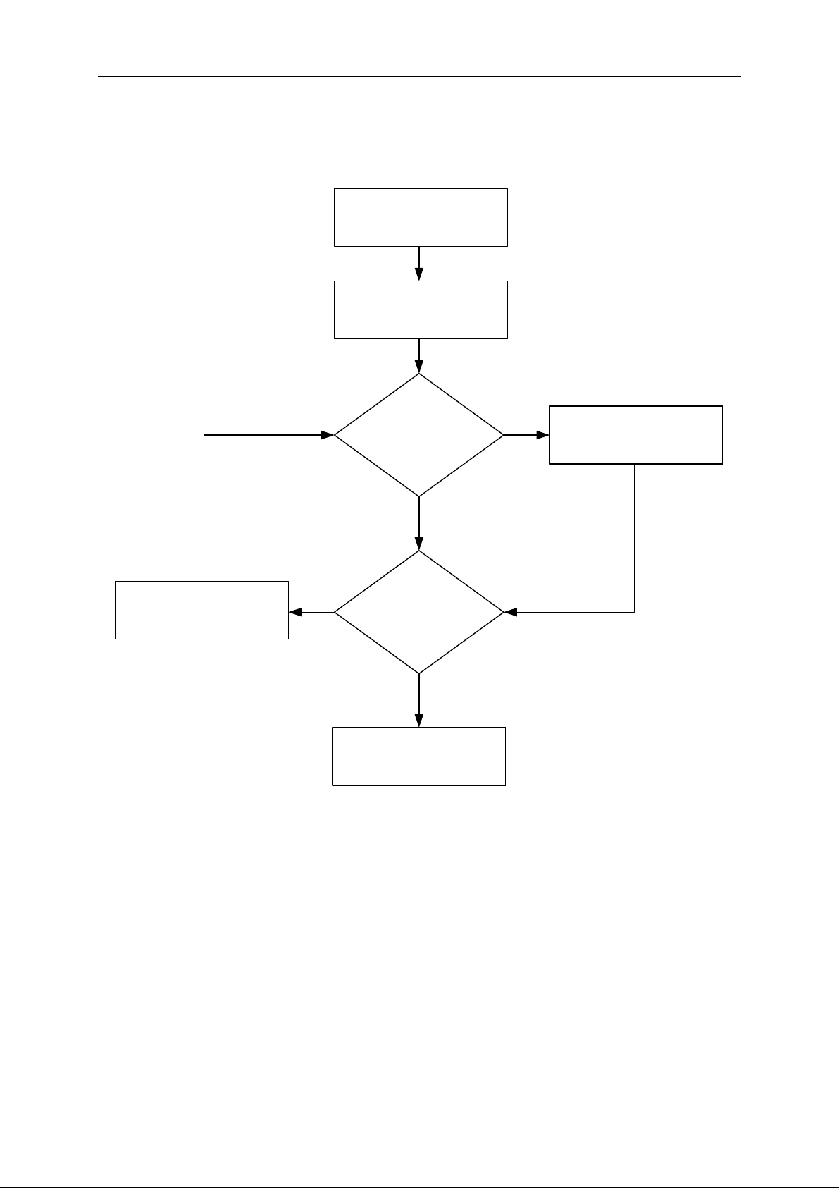
4. Operation Process Flow
Complete hardware
installation
Search for hardware
address
Reset IP address Set IP address
Yes
Reboot hardware device
Yes
No
Hardware
operation error
No
Configuration done
3
Page 10

Ethernet Configuration Tools for A620011 User’s Manual
Insert the Ethernet Card into the slot on the CSU rear panel and then turn on the CSU power.
Now connect it to network and see if the yellow LED of Ethernet Interface Connect is
always on and the green LED is blinking (see detail description in section 5.) If yes, it
means the Ethernet Card is installed successfully. Next, use the PC connected to network
to run the program as described below:
Searching for device
Figure 4-1 Hardware Device Search
Device address MAC address Serial No.
Figure 4-2 Search Completed
4
Page 11

Setting IP
Ethernet Configuration Tools for A620011 User’s Manual
Use IP Default
Self-defined
IP address
Figure 4-3 Setting IP (Skip if no need to self-define)
Reboot hardware
device
Figure 4-4 Hardware Reboot (performed when hardware device error)
Rebooting device
Activate reboot
function
5
Page 12

Ethernet Configuration Tools for A620011 User’s Manual
When reboot is
done
Figure 4-5 Reboot Finished
5. Ethernet Card
Figure 5-1 Ethernet Card
Network Cable
Connecting Port
6
Page 13

Ethernet Configuration Tools for A620011 User’s Manual
Installing Ethernet Card Here
Figure 5-2 CSU Rear Panel
Ethernet Interface Pin Assignments
Pin 1 Pin 2 Pin 3 Pin 4 Pin 5 Pin 6 Pin 7 Pin 8
TXD+ TXD- RXD+ EPWR+ EPWR+ RXD- EPWR- EPWR-
Transmit
Data+
7
Transmit
Data-
Table 5-1 Ethernet Interface Connect Pin Assignment
Receive
Data+
Power
Form
Switch+
Power
Form
Switch+
Receive
Data-
Power
Form
Switch-
Power
Form
Switch-
Page 14

Ethernet Configuration Tools for A620011 User’s Manual
LED Behaviors
LED Pin Header EM Integration Kit Digi Connect ME
Network:
Off - no link has been detected.
On - a link has been detected.
Serial port activity/Network activity:
Off - the serial channel is idle.
Blinking - serial data is transmitted or received.
TOP left
(yellow)
Top right
(green)
5(+)
7(-)
1(+)
3(-)
Table 5-2 LED Definition of Ethernet Interface Connect
6. Tr oubleshooting
Following lists the operation problems, the causes and the suggested resolutions.
Problem Cause Resolution
Unable to connect
Ethernet.
Device IP error. 1. The system is running for
L NOTICE
1. Do not insert or remove cards from the rear panel under normal operation. It may
cause the card to be damaged.
2. Make sure to follow the guide rail in CSU for installing the Ethernet Card to avoid
damages from occurring.
3. Enable Raw TCP access using TCP Port : 2101.
1. The insertion is incorrect.
2. The Ethernet Interface
Connect is malfunction.
initial communication.
2. Internal network error.
1. Reinsert the Ethernet card following
the guide rail and ensure the LEDs
are on correctly.
2. Consult with local distributor for
assistance.
1. Click Refresh List again later.
2. Consult with internal network
administrator for assistance.
8
 Loading...