

Christie Digital Systems Canada CRMX100 User Manual

RF Module
echnical Reference Information
T
DESCRIPTION
The CRMX-100 RF module is a 2.4GHz IEEE 802.15.4 transceiver designed for proprietary, Zigbee
or RF4CE application. The module is based on Texas Instruments CC2530 that combines the excellent
performance of a RF transceiver with industry–standard enhanced 8051 microcontroller unit, 128 KB
in-system programmable flash memory, 8-KB RAM, and many other features. The RF module
incorporates Texas Instrument CC2590 RF Front End power amplifier (PA) and low-noise amplifier
(LNA) for increased output power, and improved receiver sensitivity respectively. The module has an
option to either be populated with a chip antenna or reverse-polarity SMA connector to be used with an
external antenna. The RF module has various operating modes, making it highly suited for systems
where ultralow power consumption is required.
FEATURES
• 2.4GHz IEEE 802.15.4 Compliant RF Transceiver
High Performance and Low-Power 8051 Microcontroller
•
• Two Serial Unart Interface
• 2.4GHz Front End Amplifier
• Supports RemoTI stack from Texas Instruments
• 16 General Purpose I/O ports
• Chip antenna or RP-SMA connector for external antenna
• Miniature Footprint 35.80 x 23.11 mm
• Long Range up to 225 meter
• Max 10 mW output power
• RoHS compliant
OFFICIALLY RELEASED
Document Control
Dec 1, 2009
RF Module Datasheet Technical Reference Information 1 of 8
020-100489-02 Rev. 01 (11-2009)
ABSOLUTE MAXIMUM RATINGS
Rating MIN MAX UNIT
Supply voltage All supply pins must have the same
voltage
Voltage on any digital pin -0.3 VDD + 0.3,
Input RF level +10 dBm
Storage Temperature Range -40 125 °C
Reflow soldering temperature According to IPC/JEDEC J-STD-020C 260 °C
ESD
(2)
All pads, according to human-body
model, JEDEC STD 22, method A114
According to charged-device model
JEDEC STD 22, method C101
(1)
-0.3 3.9 V
V
Max 3.9
2 kV
500 V
DC
DC
1) Stress beyond those listed under the A
device. These are stress ratings only, and functional operation of the device at these or any other
conditions beyond those indicated under Recommended Operating Conditions is not implied.
Exposure to absolute-maximum-rated conditions for extended periods may affect device reliability.
2) CAUTION! ESD sensitive device. Precaution should be used when handling the device in
order to prevent permanent damage.
bsolute Maximum Ratings may cause permanent damage to
RECOMMENDED OPERATING CONDITIONS
Rating Min Max Unit
Power Supply Voltage (VDD) 2 3.6 VDC
Input Frequency 2405 2480 MHz
Ambient Temperature Range -40 85 °C
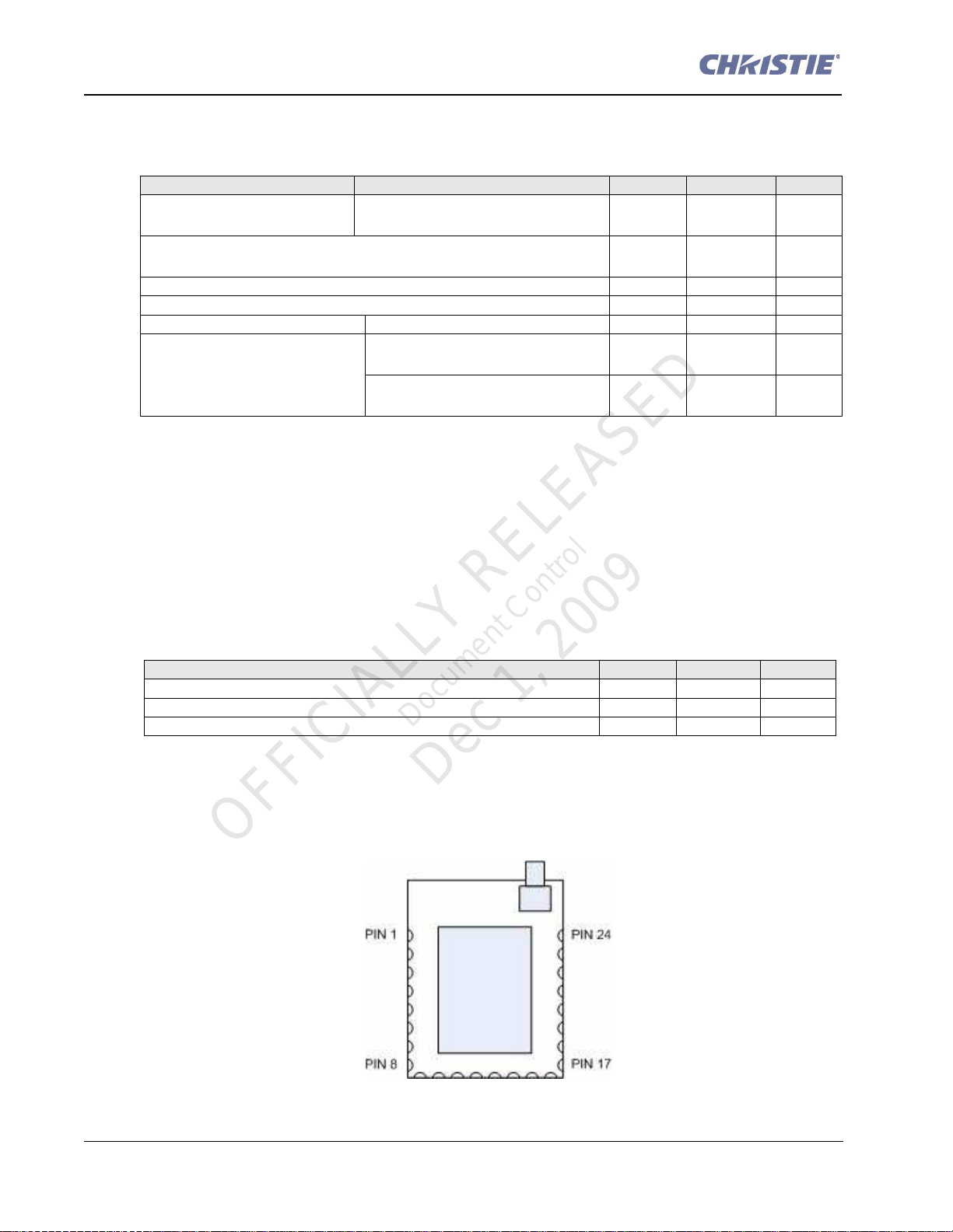
PIN DESCRIPTIONS
The RF module has 24 edge I/O pins for connecting to a host board. The following table enumerates
nd defines the RF module pinout.
a
OFFICIALLY RELEASED
Document Control
Dec 1, 2009
2 of 8 RF Module Datasheet Technical Reference Information
020-100489-02 Rev. 01 (11-2009)
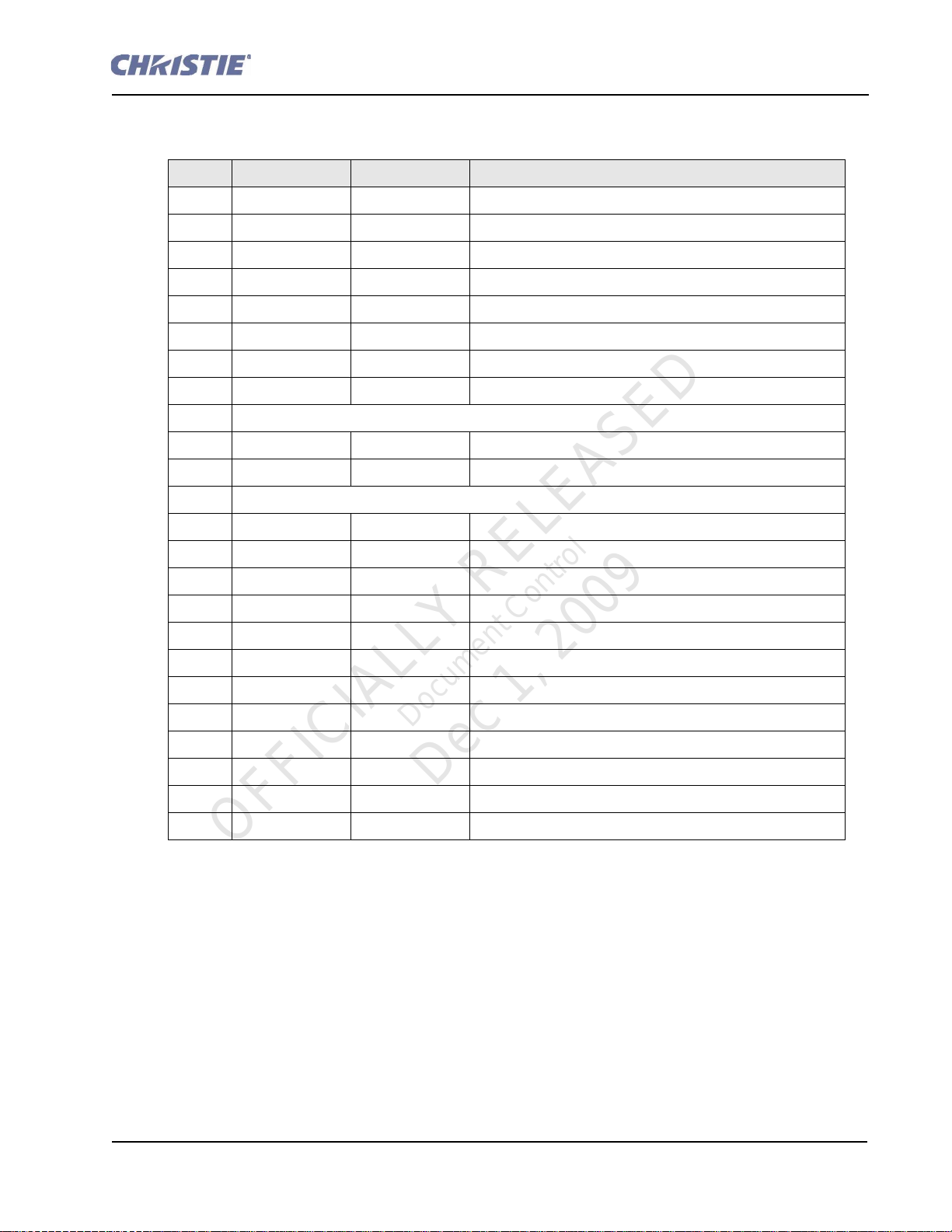
PIN PIN NAME PIN TYPE PIN DESCRIPTION
1 GROUND GND Ground
2 P2_2
3 P2_1 DI/DO/AI General Purpose Digital I/O Port 2_1
4 P2_0 DI/DO/AI General Purpose Digital I/O Port 2_0
5 P1_7 DI/DO/AI General Purpose Digital I/O Port 1_7
6 P1_6 DI/DO/AI General Purpose Digital I/O Port 1_6
7 P1_5 DI/DO/AI General Purpose Digital I/O Port 1_5
8 GROUND GND Ground
9 Not Connected
10 P1_3 DI/DO General Purpose Digital I/O Port 1_3
11 P1_2 DI/DO General Purpose Digital I/O Port 1_2
12 Not Connected
13 P1_0 DI/DO General Purpose Digital I/O Port 1_0
14 P0_6 DI/DO General Purpose Digital I/O Port 0_6
15 P0_5 DI/DO General Purpose Digital I/O Port 0_5
16 P0_4 DI/DO General Purpose Digital I/O Port 0_4
17 GROUND GND Ground
18 P0_3 DI/DO General Purpose Digital I/O Port 0_3
DI/DO/AI
General Purpose Digital I/O Port 2_2
19 P0_2 DI/DO General Purpose Digital I/O Port 0_2
20 RESET DI Reset, active low
21 P0_1 DI/DO General Purpose Digital I/O Port 0_1
22 P0_0 DI/DO General Purpose Digital I/O Port 0_0
23 VDD PI Power Supply Input
24 GROUND GND Ground
Document Control
Dec 1, 2009
OFFICIALLY RELEASED
DI= Digital Input
DO= Digital Output
AI= Analog Input
AO=Analog Output
PI = Power Input
GND = Ground
RF Module Datasheet Technical Reference Information 3 of 8
020-100489-02 Rev. 01 (11-2009)
 Loading...