

Page 1

PLEASE READ
We are in no way responsible for the
contents of the manual. We do not guarantee
its accuracy and we do not make any claim
of copyright. The copyright remains the
property of their respective owners.
Visit the site to read the latest projector
news and reviews, read and comment on
projector specifications, download user
manuals and much more.
Page 2

User's Manual
S12 and X10 Models
Table of Contents
Section Contents Page
1
2
3
Introduction
Installation &
Setup
Operation
1.1 The Projectors...................................................................................................1-1
1.2 Components......................................................................................................1-2
1.3 Purchase Record and Servicing.........................................................................1-2
2.1 Quick Setup.......................................................................................................2-1
2.2 Installation Considerations................................................................................2-2
2.3 Projector Position and Mounting......................................................................2-9
2.4 Source Connections ........................................................................................ 2-14
2.5 Power Connection...........................................................................................2-21
2.6 Operating Orientation .....................................................................................2-21
2.7 Leveling..........................................................................................................2-21
2.8 Zoom, Focus & Lens Offset............................................................................2-22
2.9 Serial Port Connections...................................................................................2-22
2.10 Keypad Protocols and Conversion..................................................................2-27
3.1 Overview...........................................................................................................3-1
3.2 Projector Basics................................................................................................3-1
3.3 Using the Keypad..............................................................................................3-5
3.4 Navigating the Menus.....................................................................................3-14
3.5 Using Inputs and Ch annels..............................................................................3-18
3.6 Adjusting the Imag e........................................................................................3-23
3.7 Configuring System Parameters......................................................................3-40
3.8 Working With the Lam p.................................................................................3-47
3.9 Projector Status...............................................................................................3-49
3.10 Using Multiple Projectors...............................................................................3-49
3.11 Error Conditions .............................................................................................3-52
4
Maintenance
Specifications
5
Appendices
6
NOTE: Due to continuing research, all information in this manual is subject to change without notice
54-017130-07P (08/02) — Software Version 2.1 Roadie S12/X10 User’s Manual
4.1 Warnings and Guidelines..................................................................................4-1
4.2 Cleaning............................................................................................................4-3
4.3 Replacing Keypad Batteries..............................................................................4-3
4.4 Replacing the Lamp and Filter..........................................................................4-4
4.5 Replacing the Lens............................................................................................4-9
4.6 Troubleshooting..............................................................................................4-11
5.1 Specifications....................................................................................................5-1
A Glossary...........................................................................................................A-1
B Keypad Reference ...........................................................................................B-1
C Menu Tree........................................................................................................C-1
D Serial Communication C ables..........................................................................D-1
E Throw Distance................................................................................................ E-1
F Optional Input Modules................................................................................... F-1
iii
Page 3
Section 1
Introduction
1.1 The Projectors
Roadie
Digital Light Processing
high-brightness and highresolution multimedia and
video projection. All models
are compatible with standard
international video formats and
can interface with IBM
compatible PC, Macintosh
computers and workstations.
They are
frequent transport and quick
installations, and are ideal for
large audience venues
demanding effortles s setup and
brilliantly sharp imag es.
Features
◊ 1280 x 1024 (1024 x 768 for X10) true resolution, other resolutions fully scaleable
◊ 12,000 ANSI lumens achievable brightness in S12
◊ Achievable contrast ratio of greater than 250:1 ANSI, 400:1 full field
◊ Tandem horizontal and vertical sizing software control
◊ Independent vertical stretch for chang ing aspe ct ra tios
◊ Keystone adjustment via menu option
◊ Interchangeable lenses for diagonal screen sizes up to 40 or more feet
◊ Display of NTSC, PAL and SECAM video input
◊ Display from PCs, VCRs, laser disc players, video cameras, etc.
◊ Memory for up to 99 custom “channels” (source setups)
◊ Intuitive on-screen menus or hidden direct control
◊ Identical built-in and remote keypads
◊ Controller and switcher compatibility
◊ Input switching with keypad
◊ Built-in RS-232 and RS-422 ports for computer control and networked projectors
◊ Remote-controlled shutter
◊ Rugged ergonomic design for harsh environments and secure handling
◊ Strong exterior panels of metal and polymer
◊ Simple hardware option for hoisting and for stacking multiple projectors
◊ Modular design for easy serv icing
projectors are powerful professional quality DMD projectors that utilize
(DLP) technology from Texas Instruments to achieve
-
robust units built for
10,000 ANSI lumens achievable brightness in X10
(optimized in X10 only)
Roadie S12/X10 User’s Manual
1-1
Page 4
INTRODUCTION
How The Projectors Work
1.2 Components
All models accept data/graphics and video input signals for projection on to front or
'
rear flat screens. High brightness light is generated by an internal 1.9 kilowatt Xenon
arc lamp, then modulated by three DMD (digital micromirror device) panels that
provide digitized red, green or blue color information. Light from the “on” pixels of
each panel is reflected, converged and then projected to the screen through a single
front lens, where all pixels are perfectly superimposed as a sharp full-color image.
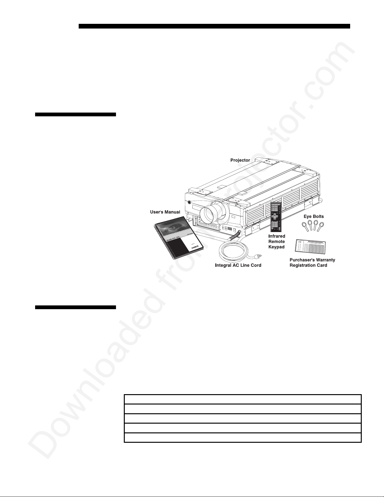
Included with the projector is an infrared (IR) remote keypad, an integral 20 amp line
cord, 4 eyebolts and a User’s Manual. Make sure that you have all these items, and
note that if you have purchased this projector, a purchaser’s Warranty Registration
Card is also included–complete this card and return it directly to Christie Digital
Systems as soon as possible.
1.3 Purchase
Record and
Servicing
Figure 1.1. Projector Components
SHOWN WITH ADDED LENS
Whether the projector is under warranty or the warr anty has expired, Christie’s
extensive factory and dealer serv ic e netw ork is alw ay s avai lab le. Ch ri stie serv ice
technicians are fully trained to quickly diag nose and correc t pro jector m alfun ct ions.
Complete service manuals and updates are available to service technicians for all
projectors.
Should you encounter a problem with the projector and require assistance, contact
your dealer or Christie. In many cases, any necessary servicing can be performed on
site. If you have purchased the projector, fill out the inform ati on below and keep wi th
your records.
Purchase Record
Dealer:
Dealer Phone Number:
Projector Serial Number*:
Purchase Date:
Installation Date, if applicable:
* NOTE: The projector serial number is located on the projector's front identification label
1-2
Roadie S12/X10 User’s Manual
Page 5

Section 2
Installation & Setup
This section explains how to install and set up the projector. If you are familiar w ith the projector and want to quickly
set it up for temporary use, follow the Quick Setup instructions below. For a more complete setup, follow the
instructions and guides covered in the remaining subsections.
NOTE: 1) The lens is not mounted when the projector is shipped from the factory. For instructions on how to install
or replace a lens, refer to 4.5, Replacing the Lens. 2) This sec ti on assumes the plug and video decoder are ins ta lle d.
Follow these steps for quick setup of the projector in a standard floor mount position.
2.1 Quick Setup
STEP 1
STEP 2
STEP 3
STEP 4
'
Position the Projector
Set the projector at the expected throw dist ance (projector-to-screen distance) and
vertical position. See 2.3, Projector Position and Mounting and Appendix E. Make
sure that the projector is level from side- to- side (see 2.7, Leveling).
'
Connect a Source
Locate the main input panel at the front of the projector. The lower left area, labeled
INPUT 1, accepts an RGB input via BNC connectors. The upper right area (assuming
the video decoder is installed) accepts a composite video at
at
INPUT 4. Connect your source to the appropriate panel connectors.
'
Connect the Line Cord to AC Power
The projector has its own integral 20-amp line cord. Use this cord only . Input power
required is 200 - 240 VAC, 50 to 60 Hz @ 14 amps for 200 V. Attach a proper AC
connector, following the wiring guide on page 5-3 (note: requires qualified service
technician). Make sure the AC on/off switch (breaker) is set to ON position and that
the line voltage indicator displays an acceptable AC level when you connect to AC.
WARNING
Do not attempt operation if the AC supply is not
within the specified voltage and power range.
'
Turn the Projector ON
Using either the built- in or rem ote key p ad, press
second to turn the projector on (or press
about five minutes. The
input panel, should glow a steady green.
POWER
LED, located in the lower right corner of the front
Powe r*
Powe r*
ON
). Let the projector warm up for
INPUT 3 or S-video input
and hold for approximately 1
Roadie S12/X10 User’s Manual
2-1
Page 6
INSTALLATION AND SETUP
g
STEP 5
STEP 6
'
Select a Source
Using either the built- in or rem ote key p ad, press
and display the image for the source you connected in Step 2. The display will resize
as needed, producing an image as large as possible for the type of source presen t.
'
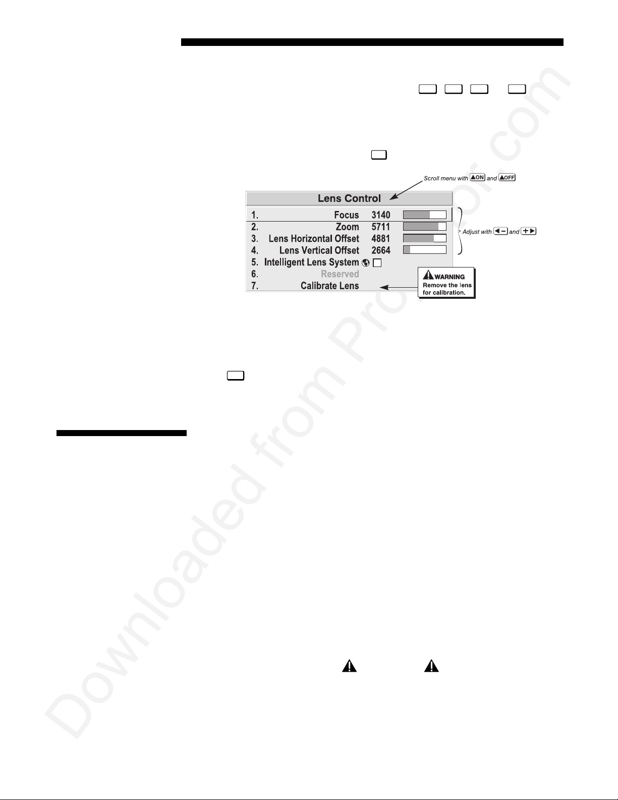
Adjust Image
With the input image displayed, press
Figure 2.1. Lens Adjustments
In the Lens menu, use the keypad as shown above to focus the image clearly and, if a
zoom lens is present, to increase or decrease image size. If desired, adjust horizontal
and/or vertical offsets to shift the lens and image location.
Lens
on any keypad.
Input1, Input2, Input3
, or
Input4
to select
2.2 Installation
Considerations
Lifting and Hoistin
Menu
Press
Channels if you want to work with other source inputs or defined channels.
Although the Roadie projector is engineered to deliver a stunning high brightness
quality output, the final display quality could be comprom ised if the projector is not
properly installed. This subsection discusses issues you should consider before
proceeding with a final installation. Even if you do not intend to use the projector in a
fixed and permanent installation, this subsection will help you to better understand
what may be done to enhance display performance.
For any new installation, yo u will likely have to safely lift or hoist the projector into
'
place. Keep in mind the following guidelines for safety.
Using the Integral Handles
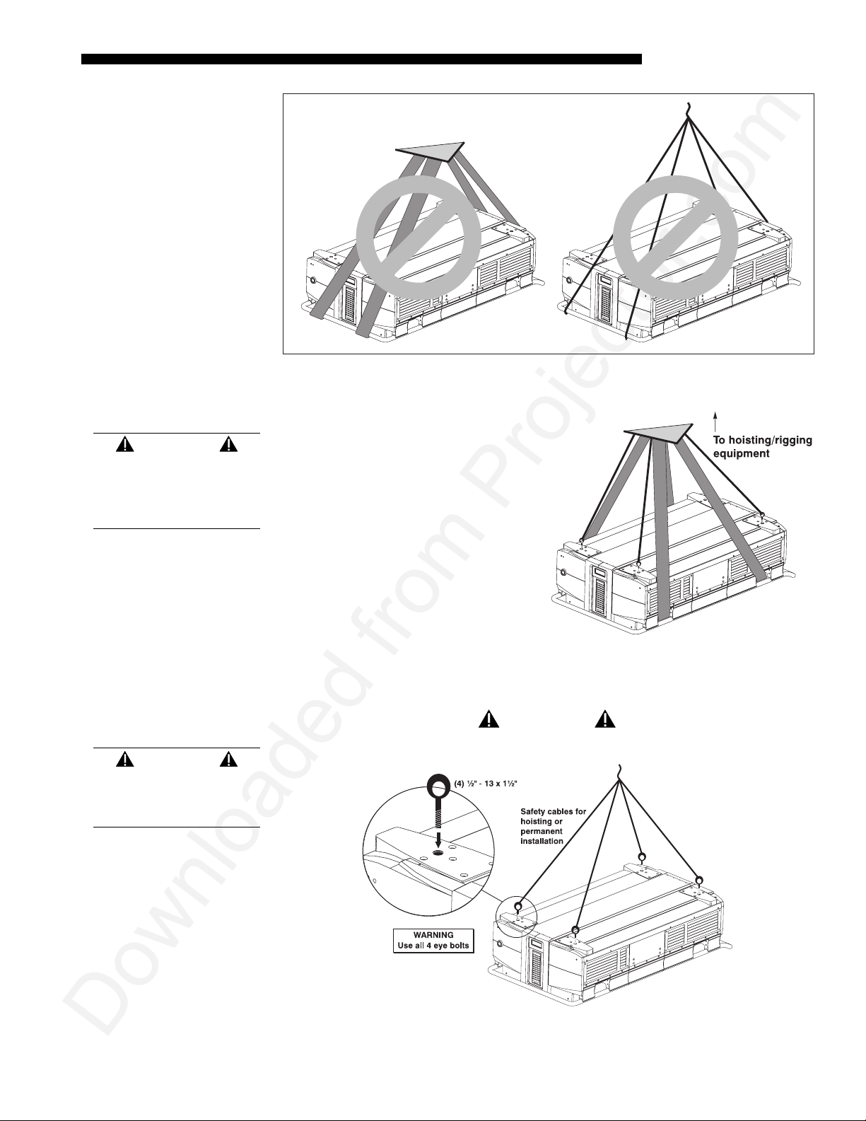
The projector includes stu rdy int eg ral wrap-around handles for convenient grasping.
While these handles are adequate for brief hand transport, such as lifting or carrying
over short distances by 2 or more people, the end handles are not intended to support
the entire weight of the projector for extended periods of time. In particular, never
hoist or suspend the projector from these end handles or use them in an installation
(see Figure 2.2).
to refine other display parameters, if necessary. See 3.5, Using Inputs and
WARNING
Use end handles for brief hand transport only.
Never suspend the projector from the side handles.
2-2
Roadie S12/X10 User’s Manual
Page 7
WARNING
Use straps or cabling
with load capacity
adequate for the
projector weight.
INSTALLATION & SETUP
Figure 2.2. Do not hoist by end handles
Hoisting
You can use appropriate webbed
strapping and hoisting/rigg ing
equipment to lift the projector and/or
install it as a permanently suspended
installation. Make sure to attach the
straps inside the side handles only, as
shown in Figure 2.3—do not use the end
or side handles. Hoist only one projector
at a time.
WARNING
Use at least 20 in.lb.
torque to attach
eyebolts.
Note that the projector also includes
tapped bolt holes in each corner that
accept screw-in eyebolts (provided).
Attach the 4 eyebolts securely (at least
20 in.lb. torque) and rig them with safety
cabling when hoisting or suspending th e pro jector.
WARNING
Remove the lens before hoisting.
Figure 2.3. Straps in Place
Figure 2.4. Attach Safety Cables
Roadie S12/X10 User’s Manual
2-3
Page 8
INSTALLATION AND SETUP
Installation Type
Choose the installation type which suits your needs: front or rear screen, floor mount
'
or inverted mount.
Front Screen, Floor Mount Installation
ADVANTAGES CONSIDERATIONS
• Easy to set up
• Can be moved or changed quickly
• Easy to access
Front Screen, Inverted Mount (ceiling) Installation
ADVANTAGES CONSIDERATIONS
• Does not take up audience space
• Projector is unobtrusive
• Projector cannot be accidentally moved
Rear Screen, Floor Mount Installation
ADVANTAGES CONSIDERATIONS
• Projector is completely hidden
• Projector is easily accessed
• Usually good ambient light rejection
Rear Screen, Inverted Mount (ceiling) Installation
ADVANTAGES CONSIDERATIONS
• Projector is completely hidden
• Usually good ambient light rejection
• Shares floor space with audience
• Installation is more permanent
• It is more difficult to access the projector
• Requires separate room
• Requires separate room
• Installation cost is usually higher
Screen Type
Rear Screen, Floor Mount with Mirror
ADVANTAGES CONSIDERATIONS
• Projector is completely hidden
• Usually good ambient light rejection
• Requires less space behind screen than
other rear screen installations
'
Front Screen Installations
• Requires separate room
• Installation cost is usually higher
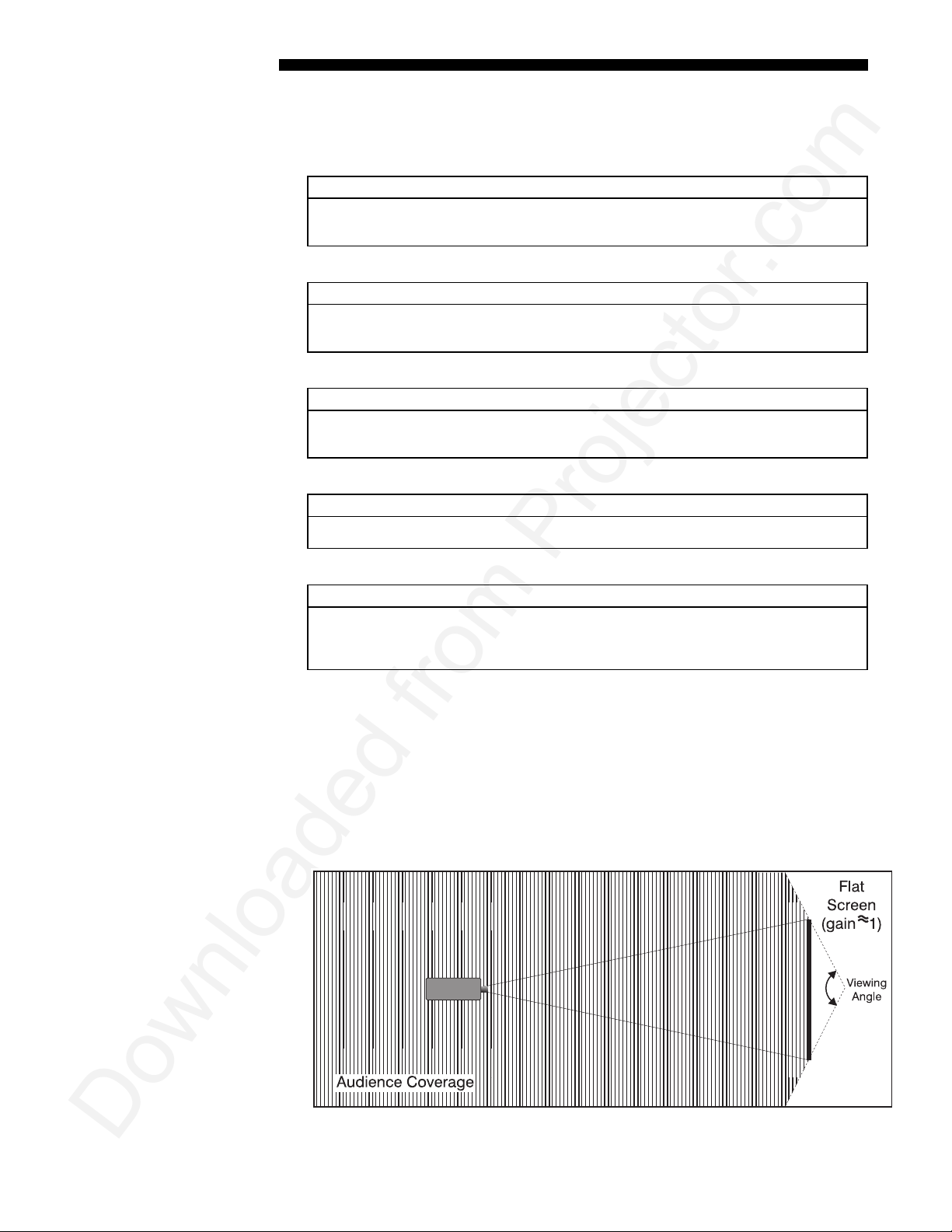
While there are two basic screen types, flat and curved, generally flat screens are
recommended for this projector. Flat screens offer a gain of about 1 with a viewing
angle just less than 180°. Incident light reflects equally in all directions so the
audience can see the display from various angles. Becau se of the low g ain, fla t
screens are most effective when ambient lighti ng is reduced, although this difference
may be negligible given the high brightness output from this projector.
Figure 2.5. Audience Coverage with Flat Screen
2-4
Roadie S12/X10 User’s Manual
Page 9
INSTALLATION & SETUP
NOTE: Lenses for this projector are designed primarily for use with flat screens, but
the projector depth-of-field range allows the lens to be focused on curved screens as
well. While focus remains sharp in the corners, there may be significant pincushion
distortion, primarily at the top of the screen.
Rear Screen Installations
There are two basic types of rear screens: diffused and optical. A diffused screen has
a surface which spreads the light striking it. Pure ly dif fuse d scree ns have a gain of
less than 1. The main advantage of the diffused screen is its wide viewing angle,
similar to that of a flat screen for front screen projection. Optical screens take light
from the projector and redirect it to increase the light inte nsi ty at the fron t of the
screen. This reduces it in other areas. A viewing cone, similar to that of a curved
front screen installation, is created.
To summarize, optical screens are better suited for brightly lit rooms where the
audience is situated within the viewing cone. Diffused screens may be better suited
when a wide viewing angle is required but there is low ambient room lighting.
Screen Size
Screen Aspect Ratio
Screen size (image size) may be from approximately 5 to 50 feet diagonal, depending
'
on the lens you are using. For instance, a 0.8:1 lens (0.6:1 as SXGA) can produce a 5
to 25 foot image size, whereas a 4-7:1 zoom lens (3.1-5.6:1 as SXGA) produces a 10
to 40 foot image size. Choose a screen size which is appropriate for your lens and
application. Keep in mind that if the projector will be used to display text
information, the image size must allow the audience to recognize all text clearly. The
eye usually sees a letter clearly if ey e-to-text distance is less than 150 times the
height of the letter. In other words, small text that is simply locate d too fa r from the
eye will be illegible no matter how shar ply and clearly it is dis played.
NOTES: 1) Screens with aspect ratios of 4:3 are typically specified by diagonal size,
but screens having other aspect ratios are not always specified by diagonal size. 2)
Stated screen sizes below refer to the diagonal size of a 4:3 screen—a 5:4 screen may
differ slightly.
Lens Type Diagonal Screen Size
0.8:1 fixed
1.5 – 2.5:1 zoom
2.5 - 4:1 zoom
4 - 7:1 zoom
7 – 15:1 zoom
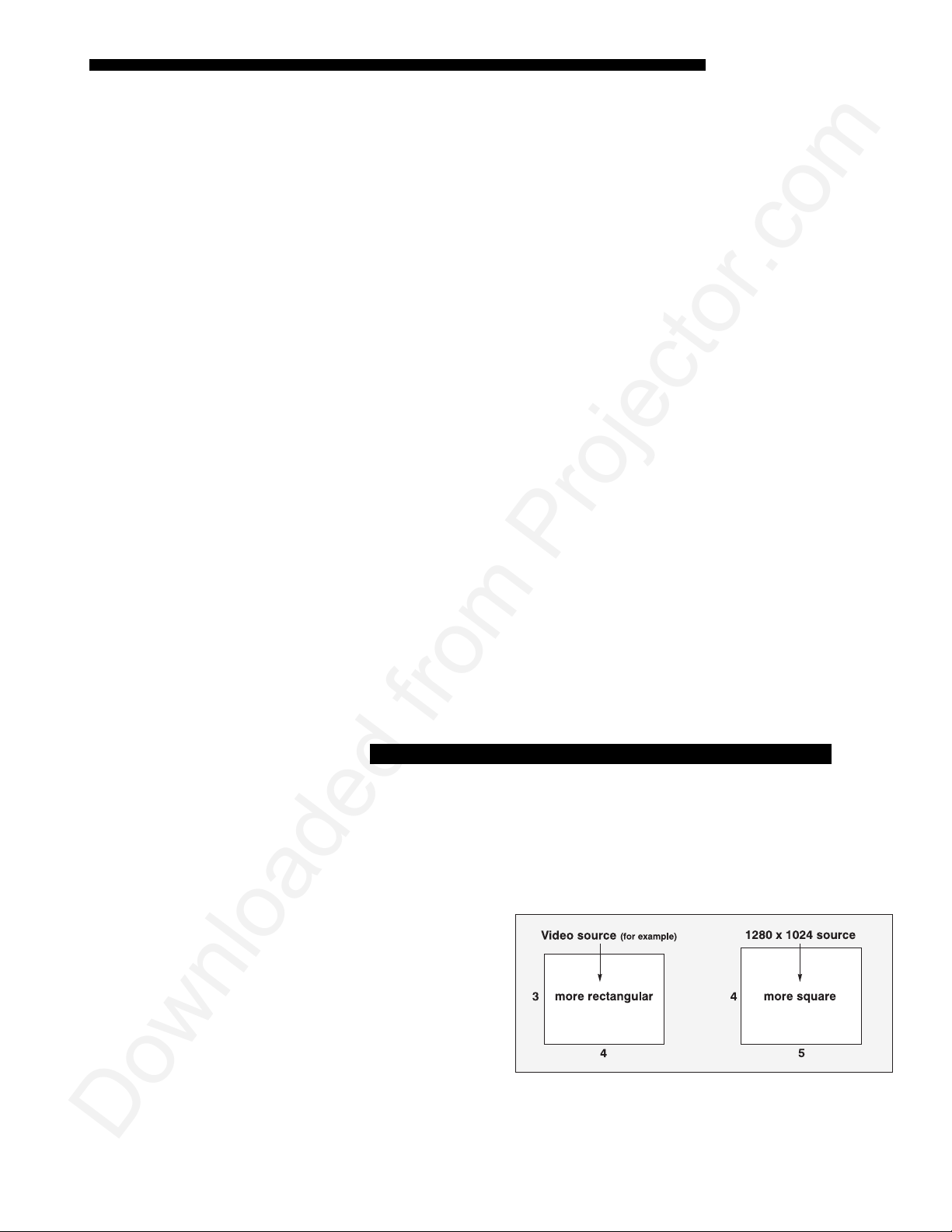
Aspect ratio describes the
'
proportion of the screen
and is expressed as the
ratio of width to height,
such as “4:3” or “5:4” (see
right). Although image size
and image aspect ratio can
both be adjusted quickly
through projector software,
it is still a good idea to
choose a screen aspect ratio
which is most appropriate for your projector. Ideally, to exactly fill a screen with an
(NOTE: 0.6:1 as SXGA)
(NOTE: 1.2 – 1.9:1 as SXGA)
(NOTE: 2.0 – 3.2:1 as SXGA)
(NOTE: 3.1:1 – 5.6:1 as SXGA)
(NOTE: 5.4:1 – 12:1 as SXGA)
Figure 2.6. Aspect Ratios of 4:3 and 5:4
5’ - 25’
6’ - 40’
6’ - 40’
10’ - 40’
10’ – 50’
Roadie S12/X10 User’s Manual
2-5
Page 10
INSTALLATION AND SETUP
g
image, the aspect ratio of the screen should correspond to the aspect ratio of the
image, which depends on the source in use. For example, standard video from a VCR
has a 4:3 ratio (approximately), whereas a high resolution graphics signal typically
has a 5:4 aspect ratio. By default,
the exception of graphics sources, will maintain their aspect ratio.
NOTE: With a few exceptions, sources with less than 1280 x 1024 resolution have a
4:3 aspect ratio. The normal aspect ratio for 1280 x 1024 sources is 5:4.
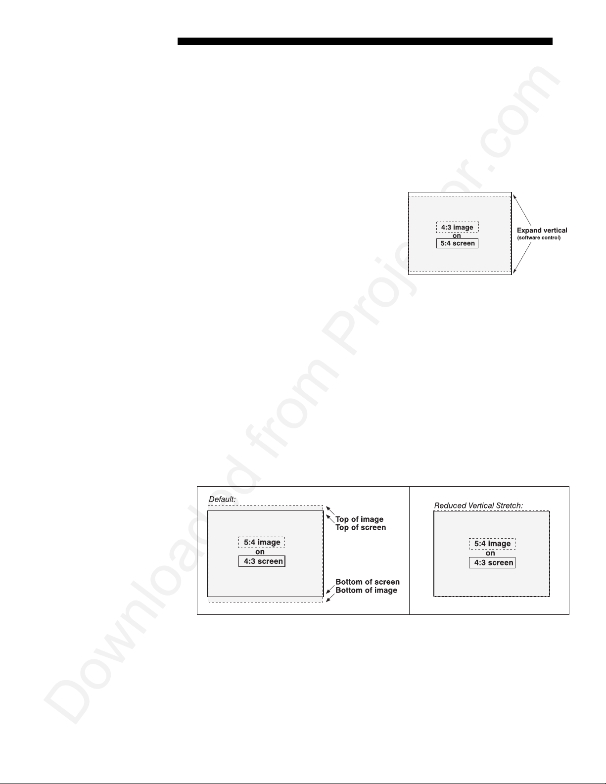
Using a 5:4 Screen with S12
If you use a mix of sources—i.e., those with
the rectangular 4:3 aspect ratio as well as
those with the slightly more square 5:4 aspect
ratio—a 5:4 screen will likely provide the
most flexibility with the S12 projector. With
one except ion, XGA images projected by the
S12 will—by default—resize to fill an SXGA
screen. The exception (illustrated in Figure
2.7) is that video signals will retain their
aspect ratio—fill the 5:4 sc reen by incr eas ing
Vertical Stretch to slightly expand the image to the top and bottom edges of the
screen. For details, see 3.6, Adjusting the Image.
Roadie
images will be as large as possible and, with
Figure 2.7. Adjusting a 4:3 Video
Image
Ideal Room Lightin
Using a 4:3 Screen with S12
If you are using a 4:3 screen with the S12, 4:3 images will—by default—slightly
overlap the top and bottom of the screen. To correct, reduce Vertical Stretch so that
the “too tall” 5:4 image no longer spills over the top or bottom of the screen (Figure
2.8). This control eliminates the need for simply moving the projector farther from
the screen, which would also result in black borders for all sources. See 3.6,
Adjusting the Image.
NOTE: The Vertical Stretch adjustment may soften the image slightly, but is rar ely
noticeable.
Figure 2.8. Using a 4:3 Screen for a mix of 5:4 and 4:3 sources (S12)
'
The high brightness output of the Roadie projector is certainly well suited for
locations where ambient lighting is less tha n optimum for projection, yet there are
still many simple things you can do to optimize your installation.
Visiting a movie theater can give you an idea of what makes an ideal projection
environment. Walls, floors and furnishings are dark and matte finished. A projection
room should not have white reflective ceilings or non-directional lighting such as
2-6
Roadie S12/X10 User’s Manual
Page 11
INSTALLATION & SETUP
fluorescent lights. The white ceiling sprea ds lig ht, m ak ing the room appear brighter.
Keep lighting and reflections to a minimum.
If it is not possible to eliminate fluorescent lights, consider using incandescent spot
lighting or parabolic refl ec tor s ("egg crates") to direct light down to the floor. Light
dimmers or rheostats allow furth e r control.
Outside windows are undesirable in any projection room. A small crack betwe en
curtains on a sunny day can wash out a projected image. If you do have windows,
make sure that window coverings are opaque and overlapping — some window
coverings are designed to provide up to 100 percent blockage of outside light.
Ideally, the material should have a matte finish.
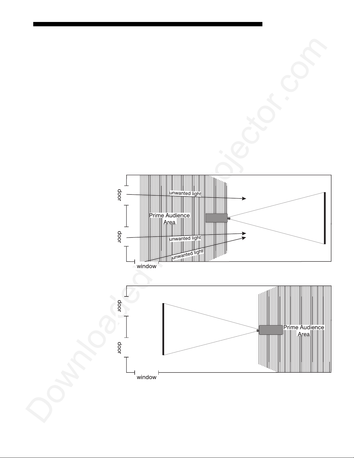
To minimize the effects caused by unwanted light from door and aisle ways,
carefully choose the position of your pro jec tor and screen. Figure 2.9 shows an
installation where poor screen placement allows too much unwanted light to enter the
screen. In Figure 2.10, screen and the projector are positioned so that unwanted light
is minimized.
Figure 2.9. Poor Screen Placement
Figure 2.10. Better Screen Placement
Even with all lighting removed it is still possible that room reflections within the
room can slightly degrade the image. Light from the projection screen shoul d be
absorbed by the ceilings, walls and floors so that it will not be reflected back to the
screen. Again, keep reflective surfaces to a minimum.
Roadie S12/X10 User’s Manual
2-7
Page 12
INSTALLATION AND SETUP
Other Considerations
Other considerations and tips which can help you improve your installation:
'
• Ventilation is an important factor when preparing a projection room. The ambient
temperature should be kept constant and below 35°C (95°F). Keep the projector
away from heating and/or air conditioning vents. Changes in temperatur e can
cause drifts in the projector circui try w hic h m ay affect per fo rmance.
• Keep the projector away from devices which radiate electromagnetic energy such
as motors and transformers. Common sources of these are slide projectors,
speakers, power amplifiers, elevators, etc.
• For rear screen applications, less spac e is required if a mirror is used to fold the
optical path.
• Choose the right screen size for the applicat i on:
◊ As screen size increases, magnification increases and reduces brightness.
Select a screen size which is appropriate for the venue, but not larger
than that required.
◊ Installing a large screen in a small room is similar to watching television
close up; too large a screen can overpower a room. A good rule of thumb
is to be no closer than 1.5 times the width of the screen.
◊ Larger scre ens requ ir e greater at tention to lighting conditions.
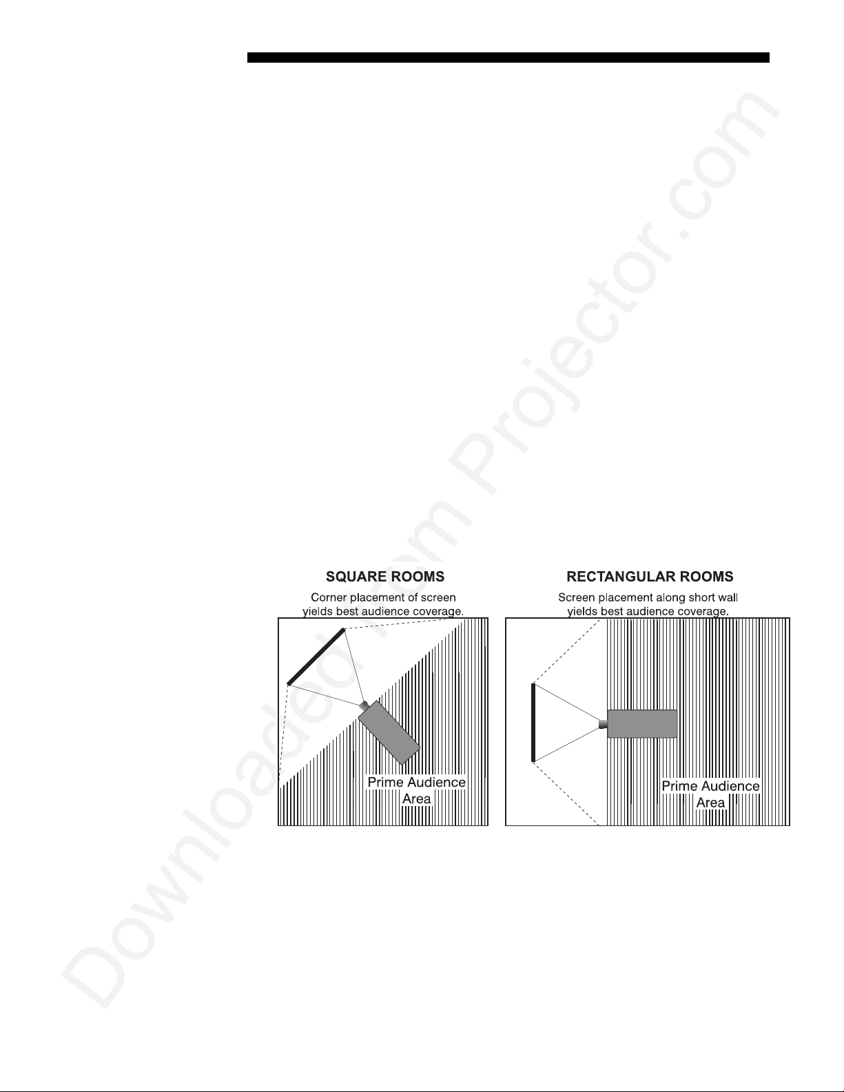
• When laying out the projection room, consider positioning the projector and
screen in a manner which wi ll achieve maximum audience coverage and space
efficiency. For example, placing the sc reen along the larger wall in a rectangular
room will reduce audience coverage. Figure 2.11 shows two examples of how
audience coverage is maximized.
Figure 2.11. Screen Locations for Maximum Audience Coverage
2-8
Roadie S12/X10 User’s Manual
Page 13
2.3 Projector
Position and
Mounting
Throw Distance
INSTALLATION & SETUP
Installation type, screen type, and lighting all affect where the projector is positioned.
In addition, both throw distance (the distance between the projector and screen) and
vertical position (the height of the pro jec tor in relat ion to the screen) m ust be
determined for every new installation. Both depend on the screen size and lens type
you are using. Make sure that the room can accommodate the required position of the
projector for the chosen screen size.
Throw distance is the distance betwe en the projector's front feet axes and the screen.
'
For any installation, an accurate throw distance must be determined in order for the
image to be of the right size for your screen–the farther the project or is from the
screen, the larger the image.
NOTE: If your projector is tilted in relation to the screen, as is sometimes the case
for large venues or elevated installations, throw distance still represents the smallest
measurement between the screen and front feet.
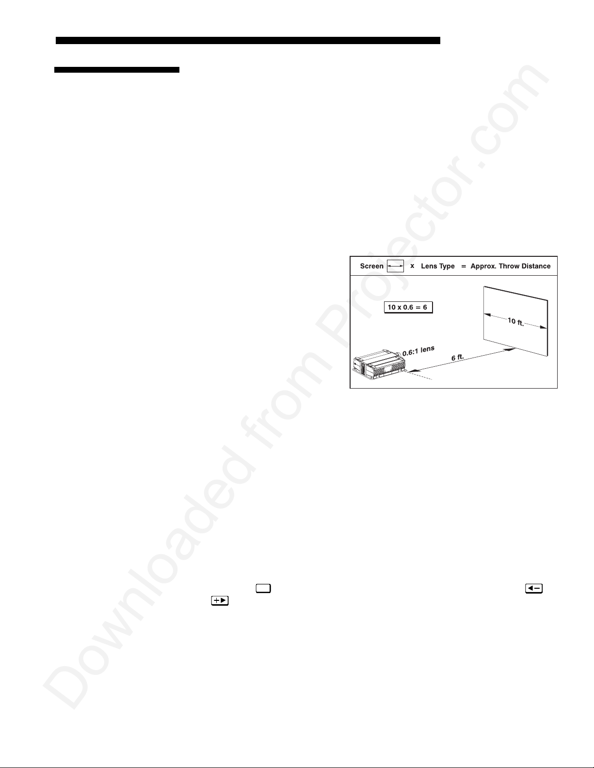
Throw distance is roughly equal
to the horizontal width of the
screen multiplied by the type of
lens you are using. For example,
if you are using a 0.8:1 lens (0.6:1
as SXGA), proper throw distance
will be approximately 0.8 (0.6 as
SXGA)
you know your screen size and
lens, you can estimate throw
distance needed—see example at
right.
IMPORTANT:
placement in an installation, always refer to the throw distance f ormula and/or
graph for your lens as listed in Appendix E. Keep in mind that due to lens
manufacturing tolerances for lens focal length, actual throw distance can vary
±5% or more between lenses describ ed as havin g the same th row ratio.
the screen width. Once
x
For proper
Figure 2.12. Estimating Throw Distance: Example
(SEE APPENDIX E FOR DETAILS)
Vertical & Horizontal
Position
THE VERTICAL POSITION
'
size of the screen and the lens type. Correct vertical posit ion helps ensu re tha t the
image will be rectangular in shape rat her than keystoned (having non- parall el sid es)
and that image focus and brightness both remain optimized.
NOTE: A keystoned image can be corrected through software in the X10. See Section
3.
In addition, vertical position of the image can be manually offset—that is, moved up
or done. Press
and . Note that the range of adjustment depends on the type of projector as well
as lens and whether or not you are also offsetting horizontally. See Table 2.1 for the
percentage of the image that can be displayed above and below the center of each
type of lens compatible with your projector. See Figure 2.13 for average X10 offsets
(non-VistaPro lenses only). All S12 offset ranges are illustrated in Figure 2.14.
NOTE: Due to manufacturing tolerances, any offset range can vary ±5% or more
between lenses described as having the same throw ratio, between projectors, and
Lens
to display the Lens Control menu, then adjust offsets with
of the projector in relation to the screen also depends on the
Roadie S12/X10 User’s Manual
2-9
Page 14
INSTALLATION AND SETUP
with any lens/projector combination. In addition, keep in mind that long throw
distances significantly reduce offset ranges.
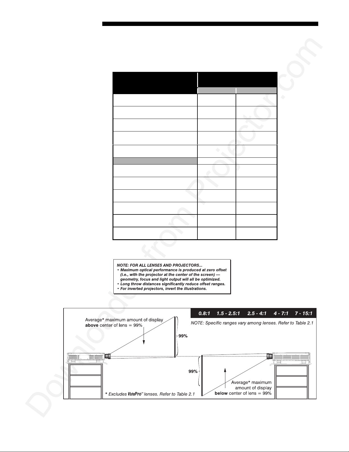
Table 2.1. Vertical Offset Ranges
Lens Type / Throw Ratio Max. Amount of Image
0.8:1 (0.6:1 as SXGA)
1.5 - 2.5:1 (1.2 – 1.9:1 as SXGA)
2.5 – 4:1 (2.0 – 3.2:1 as SXGA) × 90%
4-7:1 (3.1:1 – 5.6:1 as SXGA) × 101%
7-15:1 (5.4:1 – 12:1 as SXGA)) × 104%
Other Lenses (X10 only)
1:1 (VistaPro 1.2:1) × 75%
2.3:1 (VistaPro 3:1)
3.9:1 (VistaPro 5:1) × 95%
5.5:1 (VistaPro 7:1) × 100%
1.2 – 2.3:1 (VistaPro 1.5 – 3:1) × 86%
2.3 – 5.5:1 (VistaPro 3 – 7:1)
Above or Below Lens Center
X10 S12
× 98%
Ø 103%
× 104%
Ø 89%
Ø 90%
Ø 101%
Ø 112%
Ø 75%
× 93%
Ø 107%
Ø 91%
Ø 115%
Ø 86%
× 98%
Ø 94%
× 80%
Ø 60%
× 70%
Ø 89%
× 72%
Ø 81%
× 82%
Ø 82%
× 70%
Ø 89%
not used in S12
not used in S12
not used in S12
not used in S12
not used in S12
not used in S12
Figure 2.13. Average Maximum Vertical Offsets in X10
(NON-VISTAPRO LENSES ONLY)
2-10
Roadie S12/X10 User’s Manual
Page 15
INSTALLATION & SETUP
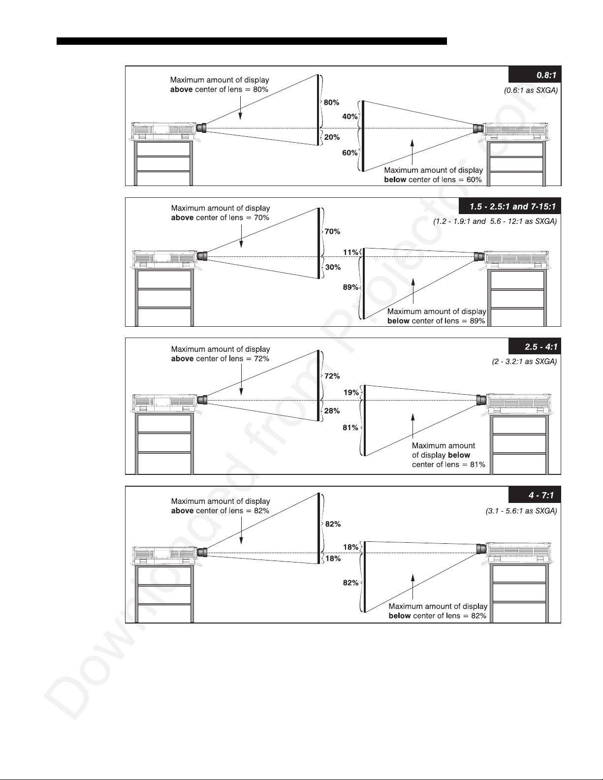
Figure 2.14. Maximum Vertical Offsets in S12
NOTES: 1) For any projector, if you cannot raise or lower the image enough using
mechanical vertical offsets, try adjusting V-Position in the Size and Position menu
(see 3.6, Adjusting the Image) when displaying at less than the maximum size. 2) If
the image becomes keystoned or exhibits uneven brightness, the projector may simply
be too high or low in relation to the screen. 3) Recommended offset ranges can
Roadie S12/X10 User’s Manual
2-11
Page 16
INSTALLATION AND SETUP
g
sometimes be exceeded, however this may affect image quality. 4) Simultaneous
horizontal and vertical offset can limit the adjustment range of each.
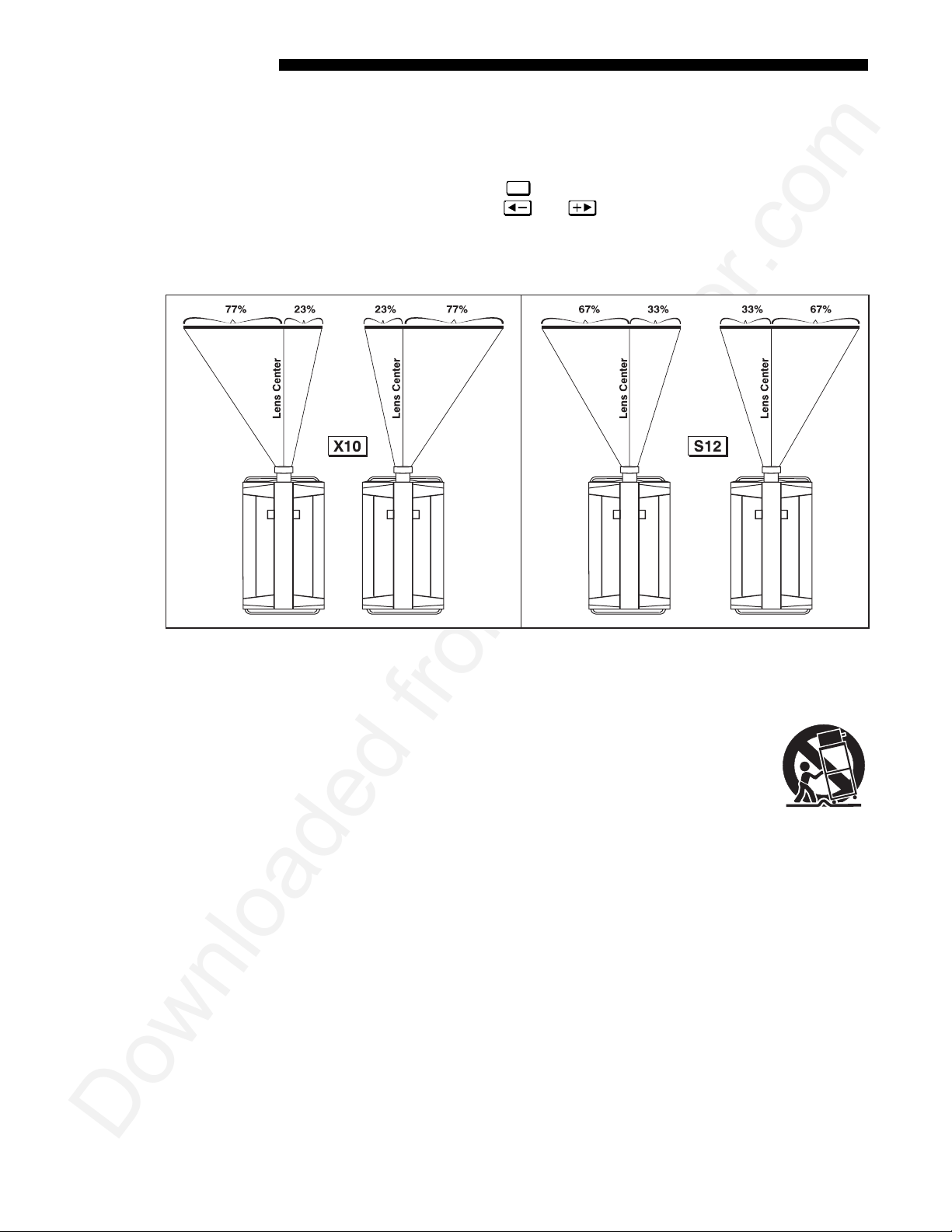
THE HORIZONTAL POSITION of the image can be offset—that is, shifted left or right
of lens center—by using the
offsets can be adjusted with
as the maximum percentage of the image that can be projected to either side of the
lens center—are shown in Figure 2.15. While offsets vary w ith lens type (see Section
5, Specifications), typical offsets are approximately 77% in X10, 67% in S12.
Lens
key. This displays the Lens Control menu, where
and . Maximum horizontal offsets—expressed
Mountin
Figure 2.15. Average Maximum Horizontal Offsets in X10 and S12
(SEE SECTION 5 FOR SPECIFIC HORIZONTAL OFFSETS FOR EACH LENS)
For typical front or rear floor mounts, mount the projector on a
'
secure table or cart. Take care with a mobile cart—avoid sudden
stops, excessive force and uneven surfaces that may cause the
projector and cart combination to overturn.
The table or cart should be reasonably level. Fine adjustments to the projector level
can be made by adjusting the height of the projec tor leg s; re fer to 2.7, Leveling for
details.
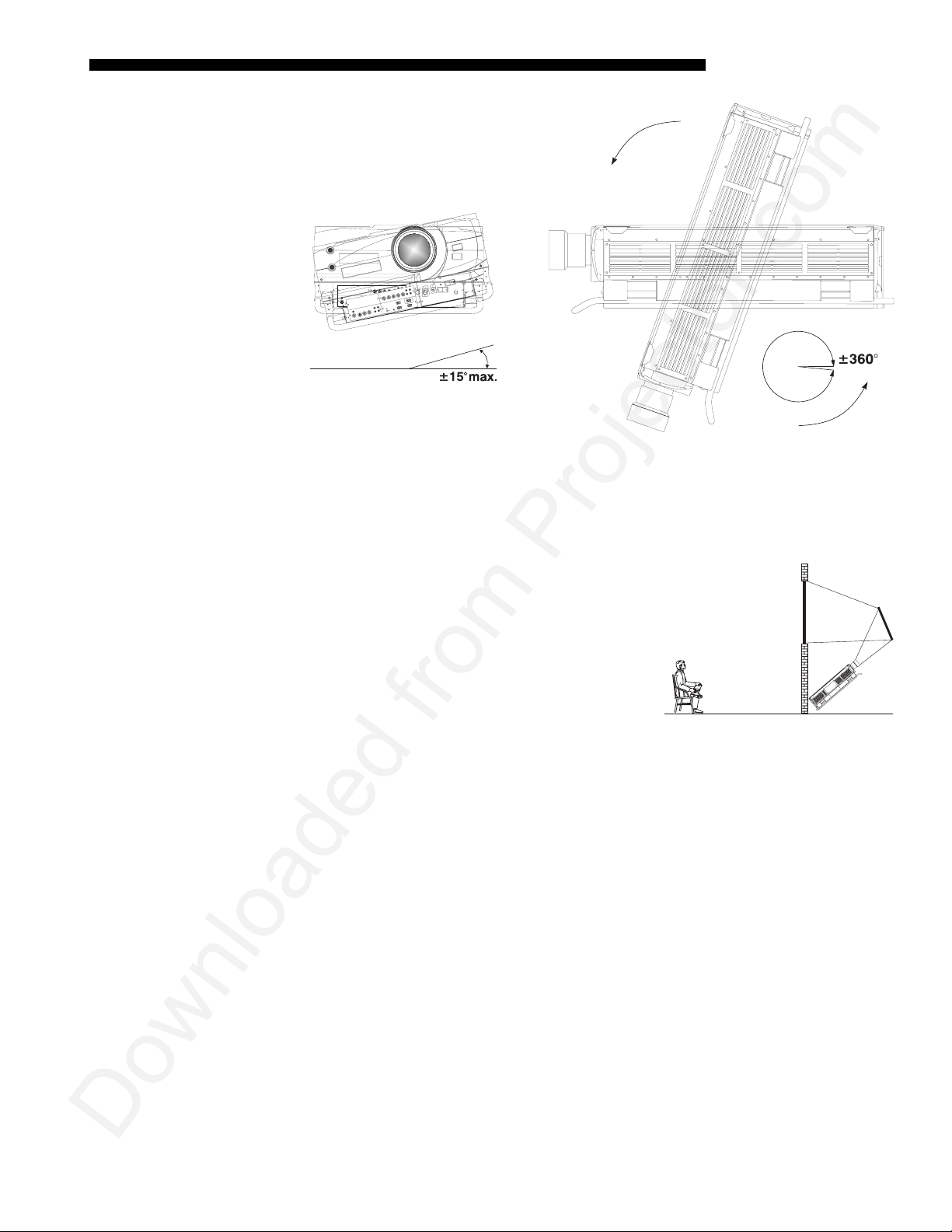
Special Mounting
Note that projector can be rotated and mounted at any vertical angle—i.e., you can
tilt the face of the projector up or down as much as desired for your installation. The
side-to-side tilt, however, must not exceed 15° (see Figure 2.16). This limit ensur es
that the arc lamp in the projector operates properly and safely. Alway s make sure that
exhaust air from the projector does not vent towards the lens, otherwise you may
detect heat waves in your projected image.
2-12
Roadie S12/X10 User’s Manual
Page 17
INSTALLATION & SETUP
p
Figure 2.16. Horizontal and Vertical Tilt Ranges
You must use the proper ceiling mount fixture or stacking kit for your projector. For
more information, contact your dealer.
Folded O
tics
In rear screen applications where space behind
'
the projector is limited, a mirro r may be used to
fold the optical path (see right). The position of
the projector and mirror must be accurately set—
if considering this type of instal la ti on, cal l your
dealer for assistance.
Roadie S12/X10 User’s Manual
2-13
Page 18
INSTALLATION AND SETUP
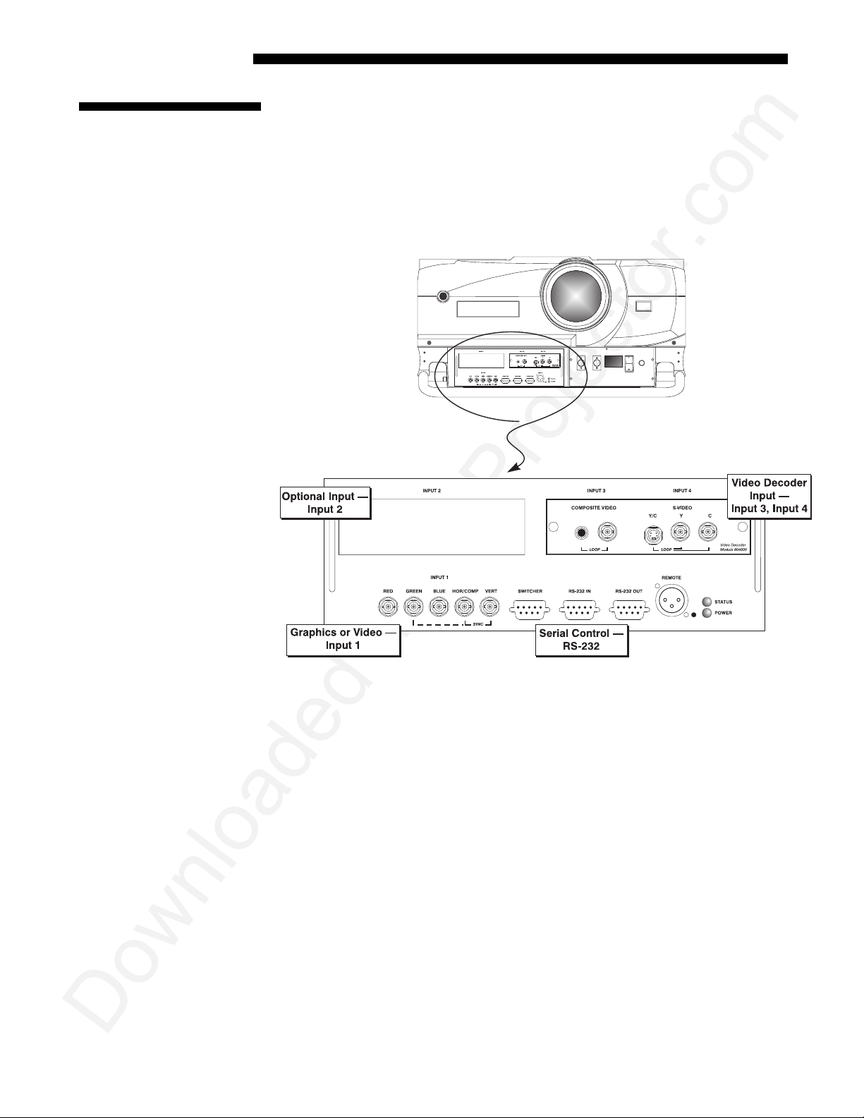
2.4 Source
Connections
The front panel of the projector provides standard input panels to which you may
connect a variety of sources. See Figure 2.17–the lower left area (
accepts an RGB signal from an external RGB source, or it can also be used for YPbPr
signals or additional video sources. The upper right panel–the Video Decoder
Module–accepts only composite video at
such as VCRs, laser disk players or DVD players. There are also several optional
interfaces available for connect ing othe r sourc es at
the upper left area, just below the proje ctor front ID label.
INPUT 3 or S-video at INPUT 4 from devices
INPUT 2. Such an option installs in
INPUT 1
) typically
2-14
Figure 2.17. Front Connector Panel
NOTE: For all connections as described in the following pages, use high-quality
shielded cables only.
Roadie S12/X10 User’s Manual
Page 19
INSTALLATION & SETUP
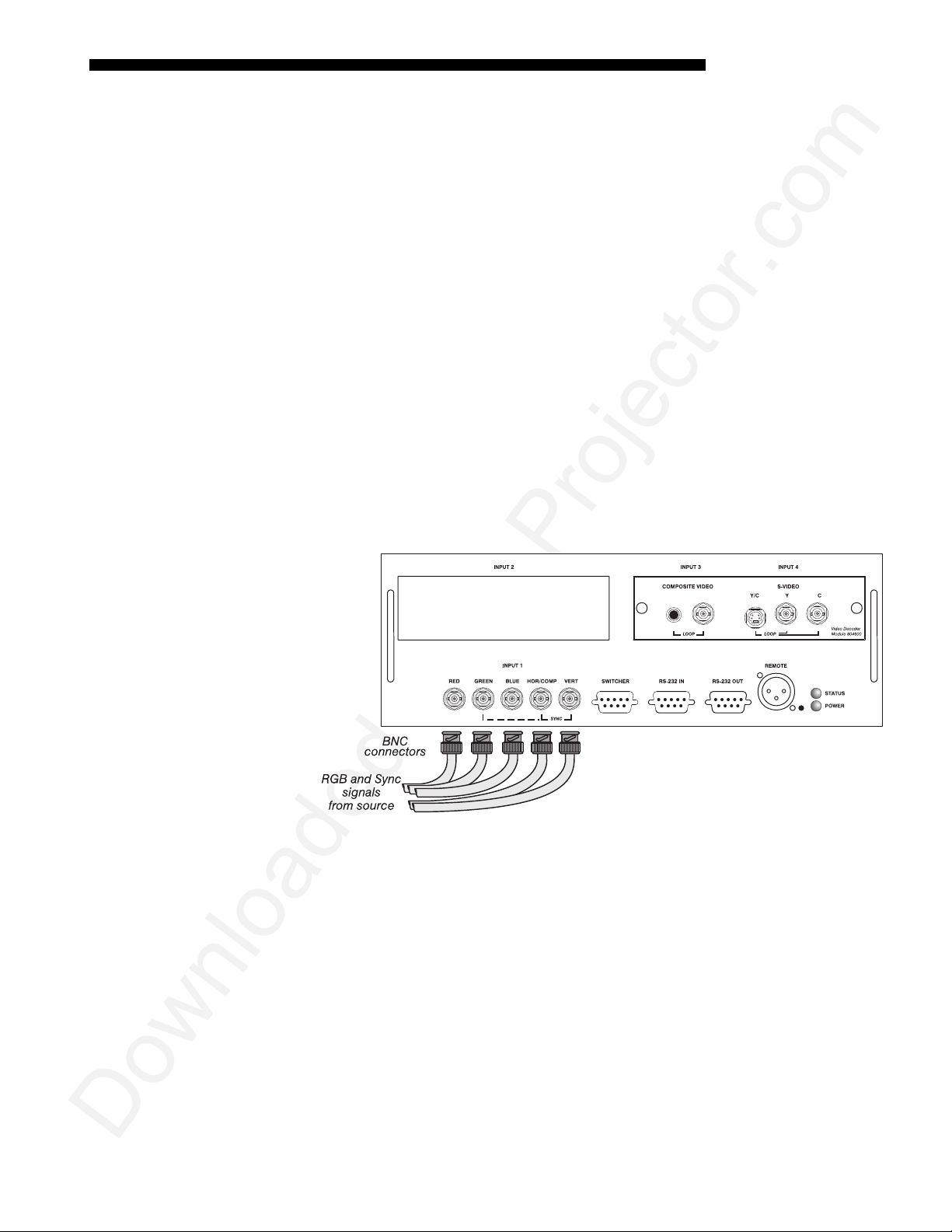
RGB Signals
INPUT 1
'
connection would be to an RGB source such as VGA, SVGA, XGA, Mac,
PowerMac, DEC, Sun, SGI and others. This projector supports multiple sync types
with RGB signals: sync-on-green, composite sync, and separate H & V syncs.
NOTE: Depending on the source, you may need a custom adapter cable with BNC
connectors at the projector end and a different type of connector at the other (such as
a 15-pin "D" connector for computer sources). Contact your dealer.
Connect the
outputs to the
sync-on-green, only the red, green, and blue connections are required. If the source
provides a composite sync output, connect it to the
the source provides separate horizontal and vertical sync outputs, connect horizontal
sync to the
labeled
NOTES: 1) If for some reason the projector fails to recognize a signal as an RGB
signal, specify this Color Space option within the Image Settings menu. See 3.6,
Adjusting the Image. 2) To connect YPbPr signals–such as from DVD or analog HDTV
sources–to
the next page.
provides 5 BNCs (connectors) for linking to a variety of sources. The typical
BNC input(s) first. Then connect the red, green and blue source
SYNC
RED, GREEN
SYNC input labeled HOR/COMP and connect vertical sync to SYNC input
See Figure 2.18.
VERT.
INPUT 1, use the red, green an d blu e BN Cs as desc ribed in YPbPr Sign als on
, and
BNCs on the
BLUE
INPUT 1
SYNC input labeled HOR/COMP. If
panel. If the source uses
Figure 2.18. Connecting RGB Input
Roadie S12/X10 User’s Manual
2-15
Page 20
INSTALLATION AND SETUP
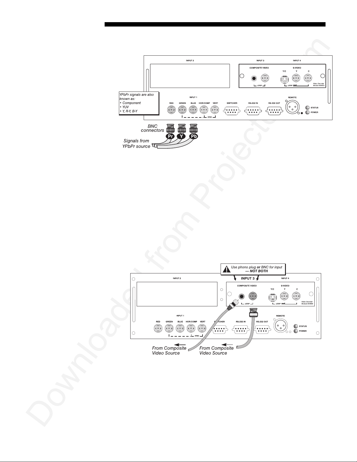
YPbPr Signals
(COMPONENT VIDEO)
Composite Video
Connect a YPbPr signal (component video) to
'
Figure 2.19. Connecting YPbPr Signal
NOTES: 1) If, for some reason, the projector fails to recognize a YPbPr signal,
specify this Color Space option within the Image Settings menu. See 3.6, Adjusting
the Image. 2) Do not connect digital component signa ls (known as YCbCr) to
1. Use the appropriate digital interface ins ta lle d at INPUT 2.
The video decoder input panel provides simultaneous connection of both a composite
'
video source (
INPUT 3) and an S-Video source (INPUT 4).
INPUT 1
as shown in Figure 2.19.
INPUT
If connecting a composite video source, use the Composite BNC connector or the
RCA phono jack at
NOTE: If you want to loop a composite signal through to another projector or
display device, see Video Loop Through later in this section.
INPUT 3
Figure 2.20. Connecting Composite Video
–do not use both as inputs. See Figure 2.20.
2-16
Roadie S12/X10 User’s Manual
Page 21
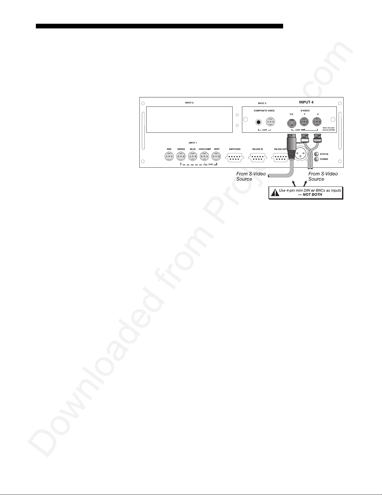
S-Video
INSTALLATION & SETUP
The video decoder input panel provides simultaneous connection of both a composite
'
video source (
If connecting an S-Video source, use the 4-pin mini DIN connector or the Y and C
BNC connectors (luma and chroma) at
2.21.
INPUT 3
) and an S-Video source (
INPUT 4–
Figure 2.21. Connecting S-Video
INPUT 4
do not use both as inputs. See Figure
).
NOTE: If you want to loop an S-video signal through to another projector or display
device, see Video Loop Through below.
Roadie S12/X10 User’s Manual
2-17
Page 22
INSTALLATION AND SETUP
p
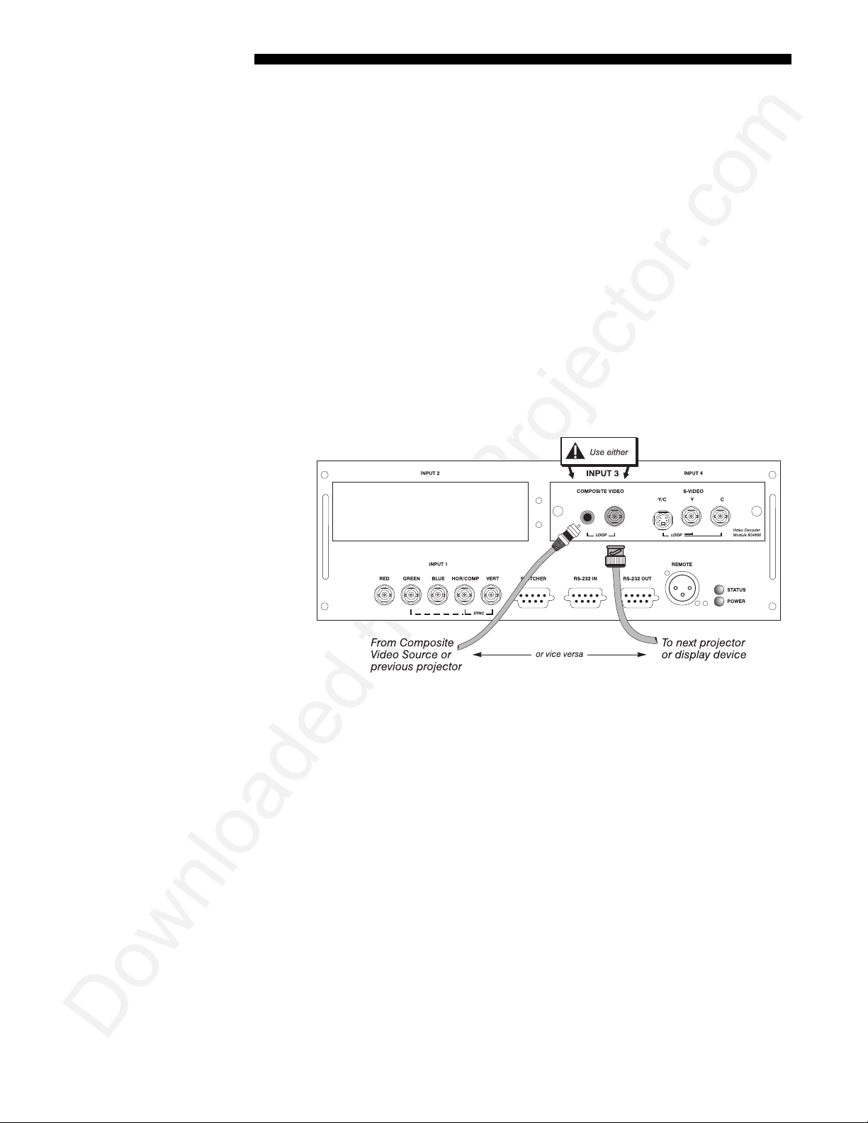
Video Loo
Through
To loop a single incoming video signal input (connected at the video decoder)
'
through to another projector or display device, use the empty connector(s) adjacent to
this same input as described below.
Composite Video Loop Through
CONNECTIONS:
to
INPUT 3 using either the small phono plug or the adjacen t BNC. Connect a second
cable from whichever
of the next display device or projector. Continue this looping method for each
projector, using either the phono plug or the adj ac e nt BNC as input into
then using the other connector as an output (i.e., loop through). Whether you use the
BNC or the phono plug as input or output depends on the type of cable you have on
hand and what type of connectors are on each end.
VIDEO TERMINATION:
Termination” is checked for the fin a l pro jec tor only. All other projectors must have
this option unchecked in order for the signal to continue. For other types of display
devices in the chain, typically a “Hi-Z” switch position is needed.
See Figure 2.22. From your source, connect a composite video signal
INPUT 3
In the Video Options submenu, make sure “Video
connector is free to one of the composite video inputs
INPUT 3,
Figure 2.22. Connections for Composite Video Loop Through
S-Video Loop Through
CONNECTIONS: See Figure 2.23. From your source, connect an S-video source signal
to
INPUT 4 using either the 4- pin m ini DIN or the 2 adjacent BNCs labeled Y and C.
2-18
Connect a second cable from whichever
video inputs of the next display device or projec tor. Cont inue th is looping method for
each projector, using either 4-pin mini DIN or the 2 adjacent BNCs as input into
INPUT 4, then using the other connector(s) as an output (i.e., loop through). Whether
you use 4-pin mini DIN or the 2 adjacent BNCs as input or output depends on the
type of cable you have on hand and what type of connectors are on each end.
VIDEO TERMINATION: In the Video Options submenu, make sure “Video
Termination” is checked for only the final pro jec to r. All ot her pro jec tors must have
this option unchecked in order for the signal to continue. For other types of display
devices in the chain, typically a “Hi-Z” switch position is needed.
Roadie S12/X10 User’s Manual
INPUT 4 connector is free to one of the S-
Page 23
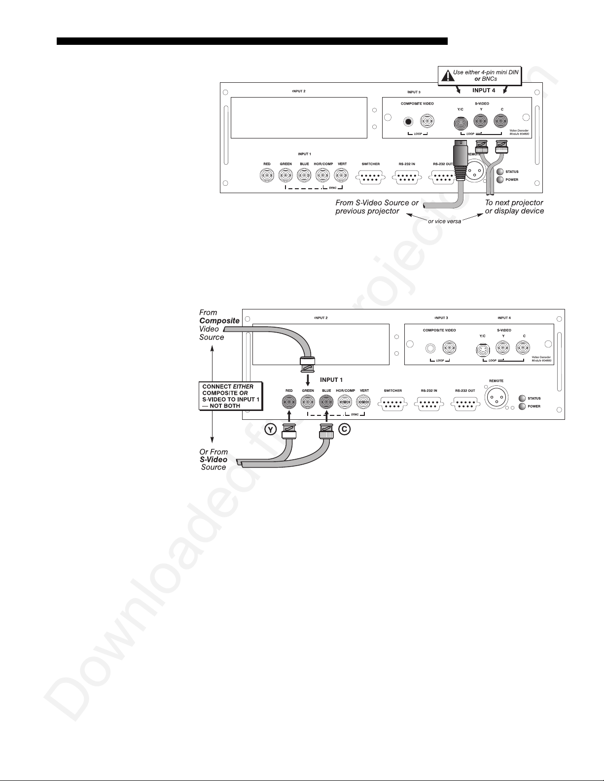
Extra Video
– COMPOSITE OR S-VIDEO
INSTALLATION & SETUP
Figure 2.23. Connections for S-Video Loop Through
If you want to use an extra video source in addition to the video source(s) connected at
'
INPUT 3 or INPUT 4 connect either a Composite or S-Video source to INPUT 1 as shown in
Figure 2.24. Do not connect both types here simultaneously. NOTE: For additional video
inputs, install an optional Composite/S-Video Input Module at
INPUT 2.
Figure 2.24. Connecting an Extra Video Source to Input 1
Optional modules allow you to increase your total num ber of inputs and/or
Optional Inputs
'
accommodate different signal types, whether analog or digital. Any one of these
modules can be installed in the area labeled
• RGB 500 Input Module
• RGB 400 Active Loop Thru Input Module
• RGB 400 Buffered Amplifier Input Module
• Composite/S-Video Input Module
• PC250 Analog Input Module
• Serial Digital Input Module
• Digital HDTV Module
• DVI Input Module
Alternatively, the analog interfaces (i.e., non-digital) can be installed in a Marquee
Case/Power Supply or Marq uee Swit che r, if desired, and used with the projector.
NOTES: 1) Optional digital interfaces cannot be used in a Marquee Case/Power
Supply or Switcher. 2) Connect analog HDTV signals directly to
INPUT 2. They include:
INPUT 1
Roadie S12/X10 User’s Manual
or to any
2-19
Page 24
INSTALLATION AND SETUP
g
“RBG” input module installed at INPUT 2—the option al HDTV Input Module used in
earlier projectors is not needed or recommended . 4) See Appendix F, Optional
Input Modules for a brief description of each interfa ce.
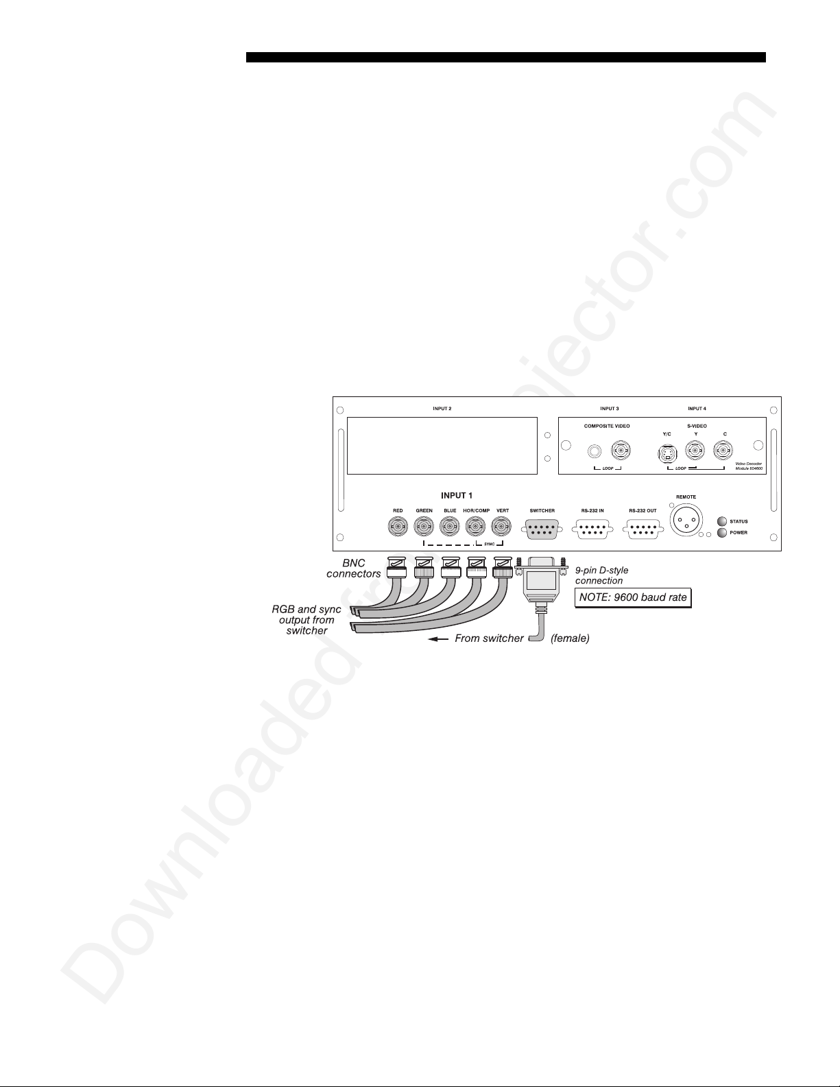
Connectin
a switcher '
You may wish to use one or more external Marquee Signal Switchers or a third party
switcher in order to significantly increase the number of sources you can select. If
you are using a Marquee Signal Switcher, connect the switcher’s RGB output to
INPUT 1 and connect an RS-232 serial communication cable between the switcher and
the projector serial port labeled
communication link (perm anently set at 9600 baud) enables you to access inputs
connected to the switcher in the same manner as those connected directly to the
projector. For most other third-party switchers, connect and access sources according
to the documentation provided with that switcher.
NOTE: Make sure any Marquee Signal Switcher connected directly to the projector
is set as “Switcher #1”. If it is not, unplug the switcher and turn the thumbwheel to
“1” before plugging back in and connecting to the projector and/or network.
SWITCHER
(see Figure 2.25). The switcher
Connecting Multiple
2-20
Roadie S12/X10 User’s Manual
Switchers
Figure 2.25. Connecting a Marquee Signal Switcher
If you are using more than one Marquee Signal Switcher, daisy-chain the RS-232
'
switcher inputs/outputs together to form a complete network of inputs accessible
from the projector (you can network up to 9 switchers), and connect Switcher #1 to
the projector as shown in Figure 2.25. In addition, connect the RGB output from each
switcher to its matching slot on switcher #1–for example, connect the RGB output
from switcher #2 to slot #2 on switcher #1, and the RGB output from switcher #3 to
slot #3 on switcher #1. Note that slots used in this manner on switcher #1 are no
longer recognized as inputs to the project or–if you select a slot lo cation that is
connected to another switcher’s RGB output, the projector will display the “no input
signal” error message.
Page 25
2.5 Power
Connection
INSTALLATION & SETUP
Plug the twist-lock ing 3- prong end of the integral line cord (30-amp, with L6-30
plug) into an appropriate grounded AC source. Twist to secure . Input voltage to the
projector must be capable of supplying between 200 and 240 VAC, 50 or 60 Hz. The
power source must be capable of supplying 2800 watts of power to the projector. See
Section 5, Specifications for complete power requirements.
WARNING
Do not attempt operation if the AC supply is not within
the specified voltage and power range.
Do not alter the line cord.
Caution: Once the projector is turned off, the lamp cooling fans will continue to
run for approximately five minutes to ensure that the projector and lamp have
sufficiently cooled, at which point the fans will automatically shut off. To avoid
thermal stress to the lamp, never unplug the line cord while the lamp cooling fans are
running. It is recommended that the main AC I/O switch (circuit breaker) remain in
the ON position at all times.
2.6 Operating
Orientation
2.7 Leveling
The projector is set up at the factory for use in a front screen, floor mount orientation.
If your initial installation is ceiling m ount or rear screen , display ed im ag es m ay be
upside down and/or reversed. To correct, you must change the image orientation
from within the Menu
Preferences menu (you may
prefer to do this before
installing the projector in its
final position/orientation).
In the Menu Preferences
menu, highlight and select
the "Image Orientation" pulldown list. Select from Rear,
Inverted Rear, Front or
Inverted Front according to
your intended installation.
See Section 3, Operation for
further information.
For most installations, the lens surface of the projector is parallel to the screen—this
prevents major keystoning of the image (i.e., an image with non-parallel sides). In
addition, the projector must be kept level from side-to-side in order for the lamp to
function safely. To make small corrections to the projector's level, rotate each leg as
necessary to raise or lowe r.
For angled installations, see
“Special Mounting” under
2.3, Projector Position and
Mounting earlier in this
section. To adjust
keystoning through
software, see Section 3.
Figure 2.26. Adjusting the Feet Height
Roadie S12/X10 User’s Manual
2-21
Page 26

INSTALLATION AND SETUP
2.8 Zoom, Focus &
Lens Offset
Zoom
Focus
Once the projector is properly set up and projecting an image, you are ready to make
quick adjustments of the m otor iz ed lens. Lens control is acc ess ed by pre ssi ng the
key on one of the keypads, which will display the Lens Control menu of options.
NOTE: Refer to Section 3 if you need help in navigating the menu.
If you have a zoom lens installed, adjust the zoom slidebar in the Lens Control menu
'
to increase or decrease the size of your image at the current throw distance.
In the Lens Control menu, adjust the focus slidebar until you obtain the best overall
'
image clarity.
Lens
Lens Offset
2.9 Serial Port
Connections
If using a computer
To ensure that the image is positioned as desired, adjust either or both offset slidebars
in the Lens Control menu. Try to achieve the desired overall image position and best
brightness while obtaining a rectangular image. If the brightness looks uneven, or the
edges do not look perfectly straight, the projector may not be in the optimal position
for your screen. See 2.3, Projector Position and Mounting for full details about lens
offset ranges for specific lenses and pro jec tor m odels.
Further display adjustments are available through keypad commands and on-screen
menus—refer to Section 3, Operation.
NOTE: Communication software is required for serial control. Contact your dealer
for details.
You may wish to use equipment other than the ke ypad for controllin g t he pr oj ect or or
for performing other special functions. Such equipment—such as most personal
computers—requires a serial interface for sending and receiving communications
through the serial ports on the projector. Note that there are two different types of
serial communication port s on this projector as described below.
'
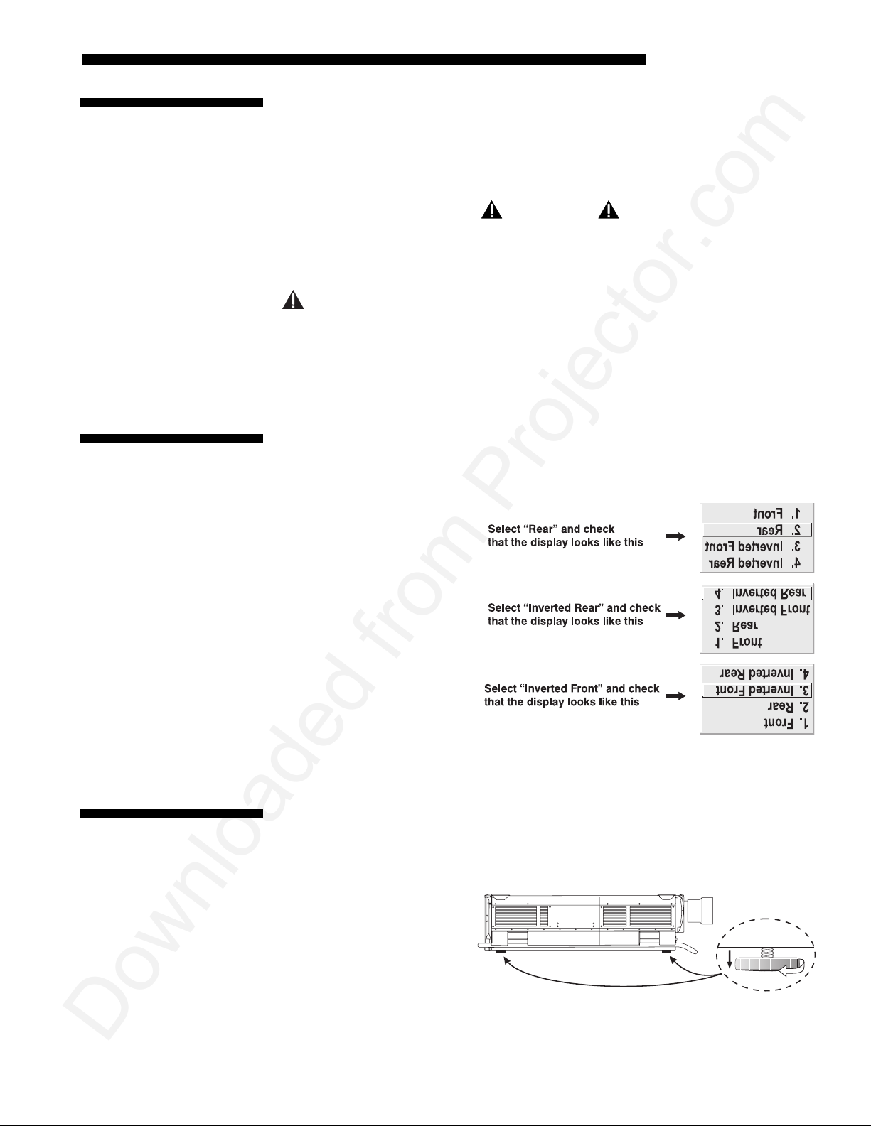
RS-232 Ports
From most computers, connect an
computer and the projector serial port labeled
is located near the bottom center of the projector's front control panel (see Figure
2.27). Then set the projector baud rate to match that of the computer (changing the
baud rate is described in 3.7, Configuring System Parameters).
RS-232 serial communication cable between the
RS-232 IN—this 9-pin D connector port
NOTE: Refer to Appendix D for complete cable wiring details.
2-22
Roadie S12/X10 User’s Manual
Page 27
INSTALLATION & SETUP
g
Figure 2.27. RS-232 Serial Connection to a Computer
RS-422 Ports
Some computers can provide
adapter or external converter) rather than the more common RS-232. RS-422
communication has differential “transmits-and-receives” and is generally better
suited for long distances than is RS-232 communication. RS-422 is not compatible
with RS-232—connecting one to the other could damage the equipment at either end.
RS-422
serial communications (often through a plug-in
If you wish to control the projector with a computer and/or other controlling device
(such as the Two-Way Controller) having RS-422 capability, connec t
communication cables between the computer (or other device) and either (or both) of
the projector serial ports labeled
locate d near the upper right corn er of the projector's front control panel ( see Figure
2.28). Use an
first consult the documentation supplied with your equipment.
RS-422 port only if your equipment has RS-422 capability—always
Figure 2.28. RS-422 Serial Connection to a Computer
Do not use an RS-422 port unless you are using a
computer with RS-422 capability. The voltage levels of
this signal can damage incompatible equipment.
RS-422—these 6-pin XLR connector ports are
WARNING
RS-422
serial
If usin
a switcher
You may wish to use one or more external Marquee Signal Switchers or a third party
'
switcher in order to significantly increase the number of sources you can select. If
you are using a Marquee Signal Switcher, connect the switcher’s RGB output to
Roadie S12/X10 User’s Manual
2-23
Page 28
INSTALLATION AND SETUP
INPUT 1 and connect an RS-232 serial communication cable between the switcher and
the projector serial port labeled
communication link (perm anently set at 9600 baud) enables you to access inputs
connected to the switcher in the same manner as those connected directly to the
projector. For most other third-party switchers, connect and access sources according
to the documentation provided with that switcher.
NOTE: See 2.4, Source Connections, “Connecting a Switcher” for complete details.
SWITCHER
(refer back to Figure 2.25). The switcher
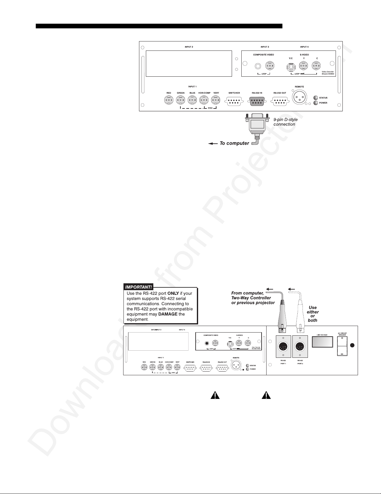
If using multiple projectors
'
Serial Communications
RS-232 NETWORK
an RS-232 interface, first set them all to the same baud rate needed, then chain the
projectors together by conne c ting the
(already connected to the computer/controller) to the
projector in the chain.
RS-422 NETWORK: To control multiple projectors with a computer/controller having
an RS-422 interface, first set them all to the same baud rate needed, then chain the
projectors together by conne c ting the
(already connected to the computer/controller) to the
next projector in the chain.
: To control multiple projectors with a computer/controller having
RS-232 OUT
Figure 2.29. Adding Another Projector via RS-232
RS-422 PORT 2
connector of the first projecto r
RS-232 IN connector of the next
connector of the first projector
RS-422 PORT 1 connector of the
Figure 2.30. Adding Another Projector via RS-422
2-24
Roadie S12/X10 User’s Manual
Page 29
INSTALLATION & SETUP
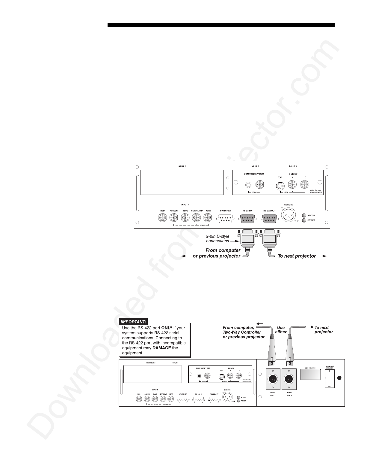
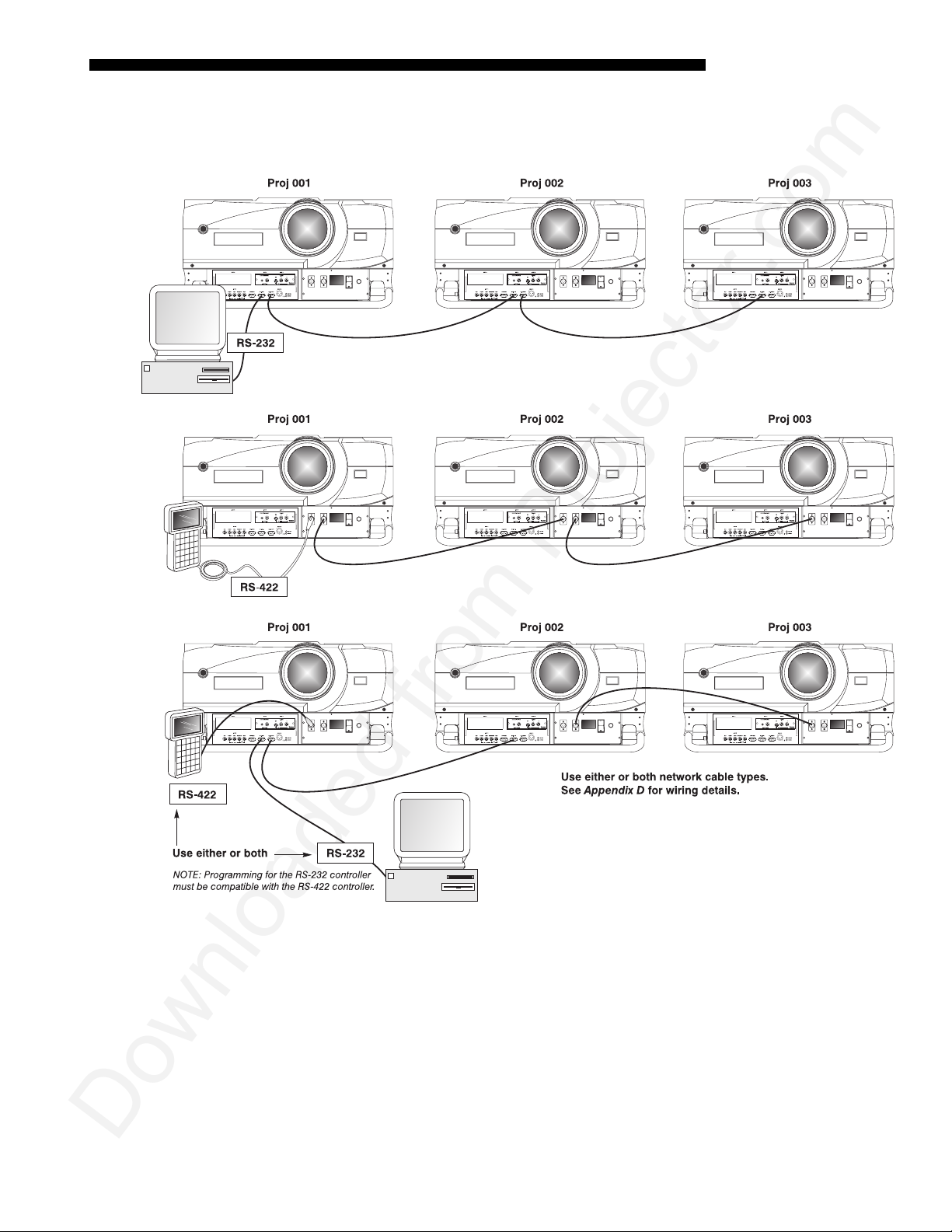
For either type of network, continue connect ing projectors in this manner until
you’ve reached the last projector in the chain, so that only the last projector has an
empty
RS-232 OUT
(or
RS-422 PORT
, if applicable). See exam ples below .
Figure 2.31. Assorted Networks
Note that communication parameters such as baud rate must be set to match the
particular controlling device before connecting as a network — re fer to the
documentation that came with your controlling device in order to determine the
proper baud rate. See 3.7, Configuring System Parameters if you need help changing the
projector baud rate from its default of 19200.
NOTES: 1) To avoid damage, connect only properly wired serial communication
cables. See Appendix D for details. 2) It is recommended that each RS-232
communication cable be no more than 25 feet in length. Use high quality cables.
Roadie S12/X10 User’s Manual
2-25
Page 30
INSTALLATION AND SETUP
p
'
Back-u
or “Split” Networks
In a typical network, broadcast serial communications or messages destined for a
specific projector travel through all serial ports in each projector regardless of
whether the messages originate from an RS-232 or RS-422 source (refer back to
Figure 2.31, bottom example). The communication path depends on the serial ca blin g
connected at each projector.
You may prefer the option of two separate communication paths—RS-232 or RS422—in your network, essentially creating a redundant “back-up” communication
path that can take over should a failed projector (or controller) prevent
communications via the other path. For this setup, connect each projector to the next
using both RS-232 and RS-422 ports.
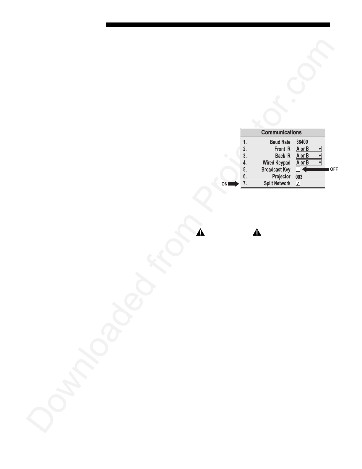
Then enable the “Split Network”
setting in the Communications menu
for each projector present so that RS232 communications remain on RS232 paths only and RS-422
communications remain on RS-422
paths only (Figure 2.32). Each
projector can then receive and send
either type of message depending on
which controller initiates the
commands—should one path fail, the second “back-up” network path can be used.
Only one network should be active at a g i ven time, as determined by the controller
(whether it is RS-232 or RS-422). Note that the “Broadcast Key” option is OFF.
Figure 2.32. Enable “Split Network”
IMPORTANT
Whenever downloading new projector software to networks, use a
single-route network only. DISCONNECT any redundant serial cabling
and UNCHECK the “Split Network” checkbox for each projector.
Two Different “Splits”
There are two differen t split ne tw ork configurations possible (Figure 2.33). Set up
whichever option best suits your application needs:
A. SPLIT NETWORK WITH ONE CONTROLLER–
want a back-up serial link, connect one controller standard (e.g., RS-232) to
one physical end of the network and the other controller standard (e.g., RS-
422) at the other physical end of the network. Make sure the “Split Network”
option is enabled in the Communications menu. If a projector should then fail
anywhere in the network, comm unication w ith the rem ainin g pro jecto rs can be
resumed in the opposite direction using the other standard. NOTE: This
configuration requires that both standards be available from a single
controller, or that you use an RS-232/RS-422 adapter.
If you have a single controller and
B. SPLIT NETWORK WITH TWO CONTROLLERS– If you have two controllers (one
RS-232 and one RS-422) and want one to be a back-up, connect each
controller to the appropriate port on the first projector in the network. Then
connect projectors together using both RS-232 and RS-422 ports as shown.
Make sure the “Split Network” option is enabled in the Communications
menu. Now, if either controller fails, you can simply switch to the other
controller and communicate via the other standard.
2-26
Roadie S12/X10 User’s Manual
Page 31

INSTALLATION & SETUP
j
Figure 2.33. Two Types of Split Networks
Pro
ector Numbers
2.10 Keypad
Protocols and
Conversion
Each projector can be assigned a unique 3-digit projector number (for example, 001).
'
These numbers are necessary when you are working with multiple linked projectors,
enabling you to direct commands to a certain projector rather than always
broadcasting to the entire network. For complete in formation on how to assign
projector numbers, see 3.7, Configuring System Parameters.
NOTE: To loop a single incoming video source through to another projector or
display device on a network, see Video Loop Through in 2.4, Source Connections.
At manufacture every keypad is assigned “A” as its default protocol, which is simply
a collection of settings that determine how the keypad operates. Once assigned, this
protocol remains in effect until it is changed—that is, the keypad will operate as it
currently does until you change its protocol.
Roadie S12/X10 User’s Manual
2-27
Page 32

INSTALLATION AND SETUP
Protocols are most useful for multiple-projector applications. For example, you might
want to change a keypad protocol if you are working with two projectors and two
remote keypads in the same room and need to control each projector independently
(Figure 2.34). When Keypad A has a different protocol than Keypad B, each keypad
communicates only with the projecto r having a matc hing protocol. Or, if you have a
network of two or more projectors connected together via RS-232 serial ports, you
may want only certain projectors to respond to a wired keypad, thus you can use
different protocols to limit responses.
NOTE: Matching the protocol on the projector to that of a keypad is done through a
setting in the Communications menu. See 3.7, Configuring System Parameters for
further information on how to change the projector 's infrare d sen sor (rear and front)
protocol.
A protocol for either type of remote keypad — IR or wired — can be changed
through software commands entered on the keypad. A new protocol set through
software commands remains in effect until the keypad batteries are removed and
replaced (if an IR remote), or until the keypad is unplugged (if a wired remote). A
remote can also be changed manually —you can "hard-wire" new jumper settings
inside the keypad so that they remain in effect until you change the hard-wiring. Note
that a hard-wired protocol can be temporarily overridden by the software protocol
change, effective until the keypad is unplugged and plugged in again (if a wired
remote) or until a battery is removed (if an IR remote).
Figure 2.34. Independent Keypads and Projectors
The standard IR remote keypad or the optional wired remote can be set to one of two
Remote Keypad
— IR OR WIRED KEYPAD —
2-28
Roadie S12/X10 User’s Manual
Protocol
'
different protocols — “A” or “B”. To hard-wire a protocol to “A” or “B” in eithe r
remote, follow Steps 1 through 5:
Step 1
Unplug the keypad from the projector (applies to wired remote only).
Page 33

INSTALLATION & SETUP
Step 2
Unlatch and open the empty battery compartment on the back of the keypad as shown
in Figure 2.35.
NOTE: A wired keypad opens as shown, but a cable passes through the battery
compartment cover.
Figure 2.35. Opening the Keypad
Step 3
Find the 4 jumpers located along the latching side of the battery compartment. These
jumpers set the keypad protocol and other settings so that the keypad functions in a
certain manner.
Step 4: Set the Jumpers
Set the jumpers as shown in Figure 2.36. Take care to refer to the correct part of the
drawing — IR or wired (optional). Use tweezers or needle-nose pliers to remove and
replace each jumper as necessary.
• J1 jumper: For either remote, set between pins 1 and 2 to set as Protocol “A”.
Set between pins 2 and 3 to set as Protocol “B”.
• J2 jumper: For either remote, set between pins 2 and 3 as shown; otherwise, the
projector will not respond correctly to keypad commands.
• J3 jumper: For the IR remote, make sure that the jumper is set between pins 2
and 3 as shown. For the wired remote, make sure that the jumper is set between
pins 1 and 2 as shown.
• J4 jumper: For the IR remote, make sure that the jumper is set between pins 1
and 2 as shown. For the wired remote, make sure that the jumper is set between
pins 2 and 3 as shown.
Roadie S12/X10 User’s Manual
2-29
Page 34

INSTALLATION AND SETUP
Figure 2.36. Locating and Setting the Jumpers
Step 5
Replace battery com partment cover. Plug into projector (wir ed keypad only) and test.
NOTE: A wired keypad can be converted into an IR remote keypad, a n d v i c e versa .
Follow the settings shown above, adding or deleting the cable and batteries as required.
The cable with 3-pin XLR connector is available separately from your dealer.
SHORTCUT METHOD:
You can also issue software protocol settings through the keypad. These software
commands will be lost when the keypad is either unplugged or when a battery is
removed — the keypad will revert back to the hard-wired jumper settings (see above)
until you enter the software commands again.
Input1 Color Pixel
Press
Input1 Color Pixel
Press
NOTE: If you change any keypad to a new protocol and the projector stops
responding, the projector may be set to a conflicting protocol. Use the projector's
built-in keypad to access the Communications menu. Under “Front IR” or “Back
IR” or "Wired Keypad", select the protocol that matches the new protocol of the
keypad at hand. The projector should now respond properly.
Posi tion
Posi tion
= Proto col “A”
= Proto col “B”
2-30
Roadie S12/X10 User’s Manual
Page 35

INSTALLATION & SETUP
g
Convertin
a Keypad
If desired, you can convert an IR remote keypad into a wired remote keypad and vice
'
versa.
TO CHANGE FROM INFRARED TO WIRED:
• Remove battery com partment cover from back of keypad.
• Remove batteries.
• Wait 1-2 minutes.
• Plug the keypad cable (availabl e separ at ely ) into the em pty batte ry
compartment. Make sure that the battery cov er is notche d sm oothly to
accommodate the cable without pinching it.
• Set keypad protocol as desired , using “wired” jumper settings.
• Replace battery compartment cover.
• Plug into the 3-pin XLR port at the front panel of the projecto r.
TO CHANGE FROM WIRED TO INFRARED:
• Unplug the keypad from the projector.
• Open the keypad back and unplug the keypad cable.
• Wait 1-2 minutes.
• Install batteries (see Section 4).
• Set keypad protocol as desired , using “IR” j umper settings.
• Replace battery compartment cover.
Roadie S12/X10 User’s Manual
2-31
Page 36

Page 37

3.1 Overview
3.2 Projector
Basics
Section 3
Operation
This section explains how to use the projector once it has been install ed. Please read
through these pages before using the pro jector for the first time. A good
understanding of projector features and how to access them will help you to take full
advantage of the capabilities of the projecto r within minutes .
NOTE: Installation involves locating the projector and adjusting it for use at that
location. If you have not yet installed the projector, refer to Section 2, Installation
and Setup.
Most projector functions and adjustments are entered through keypad commands that
either control the projector directly or activate a system of intuitive menus. Variations
in settings can be defined and retained in the projector's internal memory as a custom
channel, with up to 99 different channels possible.
Components and functions are illustrated on the following page.
Roadie S12/X10 User’s Manual
3-1
Page 38

OPERATION
p
Figure 3.1. Basic Projector Components
Lens
key on the keypad, the lens barrel of a
Lens
key on the keypad, focus adjusts the
Lens
key on the keypad, vertical and
3-2
Com
onents / Features
Roadie S12/X10 User’s Manual
REMOTE ZOOM - Accessed via the
'
motorized zoom lens (optional) rotates to adjust the size of th e image at the current
throw distance. Minimum and maximum image sizes depend on which zoom lens is
installed — see Section 5, Specifications. To adjust zoom manually, remove the zoom
adapter collar (see Section 4, Maintenance) and turn the tex tured zoom ring by hand.
REMOTE FOCUS -
sharpness of the image at the current throw distance. Focus cannot be adjusted
manually.
REMOTE LENS OFFSET – Accessed via the
horizontal offsets shift the lens and mov e the image up or down and left or right. See
Accessed via the
Page 39

OPERATION
Section 2, Installation and Setup for an illustrated explanation of offset ranges for all
lenses. Ranges are also listed on page 5-1. Offsets cannot be adjusted manually.
REMOTE CONTROL SHUTTER - Closing the shutter blocks the lens internally and turns
the image to off. Although the lamp remains “on”, its output is reduced to prevent
heat build-up. The shutter is controlled via
Shutter*
on the keypad.
COMPOSITE/S-VIDEO INPUT - Accepts a composite video and S-Video signal fro m
devices such as VCRs.
RGB INPUT - Accepts RGB and sync signals from devices such as computers, as well
as composite video, S-Video or YPbPr component signals.
RS-232 SERIAL INTERFACE (WITH LOOP THROUGH) - Allows one or more projectors to
be remotely controlled by a computer or controller, and provides a communications
connection for Marquee Signal Switchers.
RS-422 SERIAL INTERFACE (WITH LOOP THROUGH) - Allows one or more projectors to
be remotely controlled by an RS-422 compatible computer or controller (such as the
Two-Way Controller accessory). RS-422 communications can travel greater distances
than can RS-232 communications, and require RS-422 compatible equipment.
AC LINE CORD INPUT
to 60 Hz (15 amps @ 200 VAC). Always use the projector’s integral lin e cord, and
never alter this cord or plug. See complete po wer specifications in Section 5.
Do not attempt operation if the AC supply is not within
STATUS/POWER LEDS - Two LEDs (light emitting diodes) located in the lowe r righ t
corner of the front connector panel indicat e pro jecto r "Sta tus " (top ) and "Power "
(bottom). During normal operation, the "Power" lig ht is ste ady green and the "Status"
light flashes green each time a key is pressed or when the projector receives a serial
command. Use the following as a guide:
- The projector requires AC power of 200 to 240 VAC, 50
WARNING
the specified voltage and power range.
Roadie S12/X10 User’s Manual
3-3
Page 40

OPERATION
Figure 3.2. Reading the Status LEDs
NOTE: A steady red power light accompanied by a coded pattern of red and yellow
flashes from the status light indica te s an internal system err or. Con sul t the rear LCD
display for an explanation, and see 3.11, Error Conditions. If the problem persists,
contact a qualified service technician available through your dealer.
AC ON/OFF (20 A CIRCUIT BREAKER) –
down the projector to prevent damage. Keep the switch in the ON position so that AC
will reach the projector, as indicated by the adjacent Line Voltage Indicator—you
will then be able to power the projector on/off by using the
switch moves to the OFF position during operation, the projector will power off—
restart by first moving the AC switch back to its ON position, then try powering up as
key.
Powe r*
). If the breaker continues to “trip” (move to OFF), the projector
usual (press
will remain inoperable until your AC problem is corrected. It is recommended that
the switch remain in the ON position at all times. Turn the projector off with the AC
switch only if the fans have stopped, typically abou t 5 minutes after power ing off
Powe r*
with
LINE VOLTAGE INDICATOR (VOLTMETER) – During operation, this window displays the
number of AC volts the projector is receiving from the AC source. The window is
dark only when 1) the projector is unplugged or 2) there is no incoming AC, due to
the AC on/off switch being set to OFF or 3) improper AC (inadequate, excessive or
faulty) has automatically triggered the circuit breaker to open, causing a shutdown of
the projector. Monitor and make sure the display read s within the accept abl e AC
range (see Section 5) at all times.
Detects faulty AC and automatically shuts
Powe r*
key. If the AC
3-4
WIRED REMOTE KEYPAD CONNECTOR (3-pin XLR) -
control of the projector.
BUILT-IN KEYPAD - Alternative location for entering commands that control projector
performance.
LCD STATUS DISPLAY – Visual feedback for monitoring projector activities and status.
Roadie S12/X10 User’s Manual
For optional tethered remote
Page 41

OPERATION
INFRARED SENSORS - The infra red (IR) sensors on the front and rear of the projector
receive infrared signals from the IR keypad for remote control of projector functions.
For proper operation make sure that these sensor s are not blocked.
3.3 Using the
Keypad
HARD RESET -
system failure. Insert a pen point or very small screwdriver.
EYEBOLTS – Screw eyebolts into 4 corner holes (top or bottom) to hoist or suspend a
projector. See Section 2 for details.
SIDE HANDLES -
STACKING CORNERS -
three high). NOTE: All other stacking configurations require a separate hardware
accessory kit. See Section 2.
LAMP DOOR -
replacement requires a qualified service technician.
FILTER SIDE GRILLE -
The keypad appears in three locations:
Emergency access for powering dow n the pro ject or in the event of a
For safety straps when hoisting, or for brief hand transport.
For secure stacking of projectors on the flo or (maximum of
WARNING
When hoisting or stacking projectors, use Christie
stacking hardware (available separately).
For access/replacement of the interior lamp module. NOTE: Lamp
Louvered grille for air intake. Remove to replace air filters.
• Built-in to the rear of the projector
• Infrared (IR) Remote for tetherless control up to 100 feet away
• Wired Remote (optional) tethered to the front of the projector
While each keypad is identical in layout and provides complete control of the
projector, you may find one keypad more convenient than another for your specific
installation and application.
Roadie S12/X10 User’s Manual
3-5
Page 42

OPERATION
Built-in
The built-in keypad is located at the rear of the projector. An LCD window above
'
this keypad provides feedback regarding current status and activities of the projector.
Figure 3.3. Keypad
The IR Remote Keypad controls the projector by way of wireless communications
'
from a battery-powered infrared (IR) transmitter. Use the IR remote keypad the same
way you would use a remote keypad supplied with a TV or VCR. When making key
presses, direct the keypad either toward the screen or toward the front or rear of the
projector. One of two sensors on the projector will detect the signals and relay the
commands for internal processing.
3-6
IR Remote
Roadie S12/X10 User’s Manual
Page 43

Wired Remote
—OPTIONAL—
Guide to Keypads
OPERATION
The wired remote keypad connects to the 3-pin XLR jack via a 50 ft. cable. It is
'
recommended when:
• the rear keypad is inaccessible
• the lighting conditions are unsuitable for proper IR transmission
• you want to use a separate keypad for each projector in a group
NOTES: 1) For extra long distances and/or harsh environments, you may prefer to
use an optional remote Two-Way Controller to control the projector. For operating
details, please see the Two-Way Controller User’s Manual included with this
accessory. 2) Old VistaGRAPHX “Roadie style” keypads can be used with this
projector, but most
Keep in mind the following guidelines:
'
1)
Press keys one-at-a-time; there are no simultaneous ke y presses required.
2)
For any key having an “*” (
Func
key codes listed on the back are different and do not apply.
Powe r*
, for example), hold the key for approximately 1
second in order to toggle the function with a single key press. For other keys (or
to use a “*” key in conjunction with
ON
or
OFF
), a momentary press similar to
a mouse click is sufficient.
3)
Press the “lightbulb key” to temporarily illuminate the backlight for the keys
without sending any other comm and.
4)
ON
,
, and
,
OFF
repeat their “arrow” actions when held down. For
other keys, release and press again to repeat an action. In a serial network, pause
briefly between adjustments to ensure that more distant projectors can “keep up”
with the commands.
5)
If you press a key while the projector is busy with anoth er action, such as during
a power-up, the key press may not take effect.
Keypad Commands
Powe r*
Input1
When you turn on the projector it begins operating at presentation level, such as an
image from the most recently used source signal. The projector temporarily leaves
presentation level whenever you use the keypad to work with control settings, display
menus, or on-line help. For example, pressing
Menu
after startup displays the main
menu — presentation level is no longer active, although the image still appears in the
background. Press
Menu
again (or
Exit
) to return or leave the menu system and return
to presentation level.
Specific keypad commands are explained below:
'
Power ON/OFF
Press and hold for approximately 1 second to turn the projector on or off with a
single key press (note the AC I/O switc h m ust be on). Or press
immediately by
ON
or
OFF
if you want to guarantee the correct toggle (useful if
Powe r*
followed
you are unsure of the present status).
NOTES: 1) Whenever the projector is turned off, the lamp cooling fans remain on for
about five minutes to cool the lamp. 2) It is a good idea to avoid turning a projector
back on until it has been off for a few minutes. Hot re-strikes of the lamp may reduce
lamp life. 3) Do not turn off with the AC I/O switch.
Input 1
Input1
Press
This is the same as entering
to select the source connected to
Input
.
INPUT 1 on the projector (data input).
Roadie S12/X10 User’s Manual
3-7
Page 44

OPERATION
Input2
Input 2
Input2
Press
interface). This is the same as enterin g
Input3
Input 3
Press
video) . This is the same as en tering
Input4
Input 4
Press
is the same as entering
Input
Input
Press
to select the source connected to
Input3
to select the source connected to
Input4
to select the source connected to
Input
.
Input
when you want to display from a specific source location, such as a
Input
Input
INPUT 2
INPUT 3
.
INPUT 4
on the projector (an optional
.
on the projector (composite
on the projector (S-Video). This
switcher connected serially to the projector’s switcher port. The first digit represents
the number you have assigned to your switcher (usually 1-9, or “0” for one of the
four inputs on the projector). The second digi t represent s the sw itche r’s sl ot num ber
(1-9). For example:
Input
= display data from switcher 1, slot 2.
NOTES: 1) Although you don’t need to use the input key unless a switcher is
connected to the projector, you can also use
the projector itself: use
switcher), then
, , , or
as the first digit (representing the projector as the
as the second digit (the desired input slot number).
Input
to access the four input “slots” on
in combination with higher numbers is an invalid entry. 2) See 3.5, Using
Channels and Inputs for a detailed explanation of inputs.
NOTE:
Input
key behavior during a presentation depends on whether or not the
Display Channel List option is selected in the Menu Preferences menu. You can
choose to have on-screen feedback when you press
Input
, or you may prefer to enter
the desired source location “blind”, i.e., without on-screen feedback. See Menu
Preferences later in this section.
Chan
Channel
Chan
Press
to select a specific source setup (channel) defined and stored in projector
memory. Once you enter a 2-digit channel number (or, if there is a list displayed,
highlight it and press
Enter
), the display will automatically change and update
according to the numerous setup parameters defined for that channel.
NOTE:
Chan
key behavior during a presentation depends on whether or not the
Display Channel List option is selected in the Menu Preferences menu. You can
choose to use a scrollable list of channels when you press
Chan
, or you may prefer to
enter the desired channel number “blind”, i.e., without on-screen feedback. See
Menu Preferences later in this section.
Stby*
Standby
Stby*
Press
projector in a warmed-up and ready state. Or quickly press and release
follow immediately by
and hold for approximately 1 second to blank all display while keeping the
Stby*
and
ON
or
OFF
if you want to guarantee the correct toggle
(useful if you are unsure of the present status). Note that the lamp and electronics
remain ON in standby mode, even though the image turns to black and most
3-8
Roadie S12/X10 User’s Manual
Page 45

OPERATION
functions are disabled. To leave standby press and hold
Exit
Or simply press
Menu
Menu
Press
Menu
to display the Main menu. A list of several options ap pea rs for acc ess to
or
Menu
.
specific functions, such as Channel Setup or Image Settings. Press
Stby*
again (or use
Menu
remove all menus and return to presentation level.
Enter
Enter
Enter
Press
to select a highlighted item, to toggle a checkbox (checked vs. unchecked),
or to accept a parameter adjustment and return to the previous menu or image.
Exit
Exit
Exit
Press
NOTE:
to return to the previous level, such as the previous menu.
Exit
does not save changes within text editing boxes (including number
editing of a slidebars) or within pull-down lists. It acts as a “cancel” in these cases.
Arrow Keys
The arrow keys have a variety of functions depending on the situation. Some typical
uses are described below. See also Editing Text later in Section 3.
• Use
or to change a slidebar value—hold as desired for continuous
adjustment (note the adjustment increments and range depend on the
parameter being adjusted).
• Use
or to change to a different option within a pull-down list
without having to display th e lis t first
• Use
or to jump between “pages”, such as in Help or lengthy pulldown lists.
Stby*
again to
OFF
).
ON
Use the
or
increase or decrease the value in the second (bottom) slidebar of a double slidebar.
OFF
You can also use
ON
or
OFF
keys to navigate within a menu, pull-down list or text box, or to
ON
or
OFF
in conjunction with certain toggle keys—i.e., those
including an asterisk symbol—to ensure a toggle only in the desired direction. When
turning the projector on, for instan ce, you m ay be too far from the projector to know
whether it is really off or if the shutter is merely clo sed. I f you press
Powe r*
and hold it
for approximately 1 second in hopes of turning the projector on, the projector will
actually turn off if the projector was already on. Instead, to avoid the risk of togg ling
in the wrong direction, quickly press and release normally the function key you wish
to toggle (in this case
OFF
or
as desired. The specific toggle will occur.
Powe r*
). Then immediately (within 2 seconds) press either
ON
Toggle keys are labeled with an asterisk on the keypad. They are listed below:
•
•
•
Shutter*
Shutter*
Stby*
Stby*
Powe r*
Powe r*
ON
+
+
= close the shutter
OFF
= open the shutter
+ ON = put the projector in standby mode
OFF
+
+
= leave standby
ON
= turn the projector on
OFF
+
= turn the projector off
Roadie S12/X10 User’s Manual
3-9
Page 46

OPERATION
Color
Color
Press
Mute*
•
Mute*
OSD*
•
OSD*
Color
to adjust the color saturation level, i.e. the amount of color in a video
+
+
+
+
ON
= turn the menu display on
OFF
= turn the menu display off
ON
= turn the menu system on
OFF
= turn the menu system off
image. Lower settings produce less saturated co lor s — a setting of “0” produces a
black and white image, for example. If the color level is too high, c olor s will be
overpowering and unrealistic. Use
level is displayed. The
Tint
Tint
Tint
Press
to adjust the red/green color hue for tru e color re pro d uc tio n o f video and
Color
key has no effect when using ADP.
and until the desired color saturation
HDTV signals. For best result s, adjus t tin t while disp laying an external test patte rn—
otherwise, it is recommended that tint remain at its default setting. Use
until the desired tint is achieved. This function can be used with digital sources.
Detail
Detail
Detail
Press
video). Use
to adjust the sharpness of a video image (it is of limited use for non-
and until the display is as sharp as desired, keep ing in m ind
that any level of detail above 3 will also introduce a certain degree of noise in the
image. Set below 3 to filter the signal and remove noise from a noisy source.
and
Cont
Contrast
Cont
Press
to change the amount of white in your images. Use and until you
reach the desired level of contrast—for best results, start low and increase so that
whites remain bright but are not disto rte d or tinted, and that light areas do not
become white (i.e., are “crushed”). Conversely, low contrast causes dim images. See
3.6, Adjusting the Image (Image Settings subsection).
Bright
Brightness
Bright
Press
to increase or decrease the amount of black in the image. Use and
until you reach the desired level of contrast—for best results, start high and
decrease so that dark areas do not become black (i.e., are “crushed”). Conversely,
overly high brightness changes black to dark gray, causing washed-out images. See
3.6, Adjusting the Image (Image Settings subsection).
Vol
Volume
This key is not functional on this pro jec tor, as there is no audio capabil ity .
Proj
Projector
Proj
Press
when you want to access a specific projector within a network or if you
simply need to see if the local projecto r is listening. The number appearing in the
“Enter Number” window indic ate s whic h pro jecto r is curr ently li ste n ing to
commands, and will match the projector number that has been defined in its Menu
Preferences menu.
The “Projector” checkbox (read- only ) shows whether or not the pro jec tor phy sically
connected to a keypad is listening to commands from that keypad. A checkmark
3-10
Roadie S12/X10 User’s Manual
Page 47

OPERATION
means that connected projector is listening; if there is no checkmark, you are
communicating with a differ en t projecto r.
To use a specific projector, enter the 3-digit number assigned to the projector you
want to use. Press
Enter
to select, press
Exit
to cancel. If you switch to a projector
other than the one you are currently using, the checkmark will be deleted.
Pixel
Posi tion
To broadcast to multiple projectors, press
Proj
and then
Proj
again without entering a
projector number. Keypad commands will then affect all projectors present.
NOTES: 1) The "Broadcast Keys" option in the Communications menu must be
selected for only one (any) projector in a serial network. The keypad in use must be
OFF (disabled) for the remainin g pro jectors. See 2.10. Keypad Protocols and
Conversion, and 3.7, Configuring System Parameters.
Pixel
Pixel
Press
tracking first: use
to access the pixel tracking and pixel phase double slideb ar. Adjus t pixel
and to increase or decrease the frequency of the pixel
sampling clock to correct image consistency and aspect ratio. For proper phase, use
ON
and
OFF
to increase or decrease pixel phase so that any shimmer disappears and
the image is stable throughout. See 3.6, Adjusting the Image (Size and Position
subsection) for a complete explana tion of tracking and phase.
Position
Posi tion
Press
and to move the image left or right, use
down. Note that
to move the image using the double slidebar. At the slidebar, use
ON
Posi tion
does not affect lens position, but rather what portion of the
and
OFF
to move the image up or
available pixel area in the projector is used for displaying the incoming signal (1280
x 1024 for S12, 1024 x 768 for X10).
Lens
Lens
Lens
Press
to display the Lens
Control menu ,where you can
access motorized control of
horizontal/vertical offsets,
focus and zoom, or turn the
Intelligent Lens System
™
on
or off. All slidebars are
adjusted with
and .
NOTE: Since the direction of
lens travel affects the exact final position of the lens, setting a lens position (focus,
zoom or an offset) may cause the lens to reverse its direction of travel, depending on
its starting point, so that it approa ches the se tt ing from the corr ect di rec tio n. Any
even-numbered setting is approached from above (the slidebar values will decrease),
any odd-numbered setting is approached from below (the slidebar values will
increase).
FOCUS: Adjust the image clarit y.
ZOOM: Enlarge or shrink the image (requires a zoom lens).
HORIZONTAL OFFSET: Shift the lens and image left or right.
VERTICAL OFFSET: Shift the lens and image up or down.
Roadie S12/X10 User’s Manual
3-11
Page 48

OPERATION
INTELLIGENT LENS SYSTEM: Enable “Intelligent Lens System” to add the 4 lens
positions—focus, zoom, horizontal and vertical offset—to the current channel
settings recorded in projector memory (see 3.5, Using Inputs and Channels if you are
unfamiliar with channels). This featu re is part icu la rly use ful if you are using sources
with radically differen t aspec t ratios, such as anamorphic vs. 5:4. When switching to
and from such displays, for example, the lens will automatically move to the last
position defined for each channel, automatically opt imizing the display fo r focus,
zoom and offsets. Delete the checkmark if you want to use consistent zoom, focus
and offset settings for all channels—the lens will not move unless you re-adjust a
lens setting.
CALIBRATE LENS:
Select “Calibrate Lens” to ensure that the mid-point for each of the
four lens functions is defined as such in software, and that the lens mount movements
remain accurate to this reference. Regular calibration can correct for slight eventual
mechanical “drifting” of lens mount movements over time. It is particularly
recommended whenever the projector is bumped or subjected to vibration, and it is
required after certain service procedures.
IMPORTANT
It is recommended that you
REMOVE THE LENS before calibration.
Shutter*
Mute*
During calibration, th e lens mount will mov e in variou s direct ions for app roximately
20 minutes, and a small “Lens Calibrating” message will appear on screen.
Calibrating an empty lens m ount (i.e., no lens or collar) ensures that nothing can
bump into the optics during the process. Calibration is complete when lens mount
movement stops—the sound of the motors will permanently cease. The Lens Control
menu then reappears on screen.
Shutter
Press and hold
Shutter*
for approximately 1 second to toggle the shutter closed or open
with a single key press (this also blank s the image electronically ). Or quickly press
and release
Shutter*
and follow immediately with ON or
OFF
if you want to guarantee
the correct toggle (useful if you are unsure of the present status). Close the shutter
whenever you want to mute all display yet maintain access to projector functions.
Open the shutter to regain the display.
NOTES: 1) The status of the shutter is shown in the LCD window on the rear panel of
the projector. 2) Upon power-up, the shutter is open. 3) The lamp remains on.
Mute
Mute*
Use
to temporarily hide the current menu—press and hold for approximately 1
second to toggle the menu on or off with a single key press. Or quickly press and
release
Mute*
and follow immediately with ON or
OFF
if you want to guarantee the
correct toggle (useful if you are unsure of the present status).
Func
Function Key
From presentation level, press
color or colors in the display. For example,
Func
data,
will display all colors data. The list of available color combinations is
Func
followed by a 2-digit number to enable a specific
Func
will display only red and green
shown below and also appears on the back of the IR remote keypad. Color enabling
can also be accessed in various locations within the menu system.
3-12
Roadie S12/X10 User’s Manual
Page 49

OPERATION
NOTE: Once
Func
Func
Func
Func
Func
Func
Func
Func
is pressed in presentation level, the projector will not respond to
= Red
= Green
= Blue
= Red and Green
= Green and Blue
= Red and Blue
= All colors (
Exit
does the same thing)
non-numeric entry until 2 digits have been entered or 5 seconds have elapsed.
Use of the
elsewhere in Section 3. For example, press
Func
key within the menu system is noted with the appropriate topic
Func
in the Channel Setup menu to enable
deletion or copying of a channel.
OSD*
OSD (On-screen display)
OSD*
Press and hold
visible or invisible). Or press
for approximately 1 second to toggle menus on or off (i.e.,
OSD*
followed immediately by
ON
or
guarantee the correct toggle direction (useful if you are unsure of the present status).
Note that invisible menus are fully functional.
NOTES: 1) With OSD on, you can still hide menus, error messages, slidebars, etc.
with the appropriate setting in the Menu Preferences menu. 2) The status of the
key is displayed in the LCD window at the rear of the projector.
OFF
to
OSD*
Help
Help
Help
Press
again to exit. From presentation level, press
for detailed information about any current menu and highlight. Press
Help
to access the General Help menu
consisting of Using Help, Setup, Keys, Source (Input) Selection, Stat/Pwr LEDs and
Using 3D. Press
Tes t
Test
Tes t
Press
to display one of the several available test patterns. Press
display the next available pattern in the sequence.
or press
Exit
Exit
to leave General Help and return to presenta tion level.
Tes t
again to
Tes t
will exit after the last pattern,
at any time to remove the current test pattern from the screen and return
to presentation level.
NOTE: For a complete list of all test patterns, see the Configuration (Geometry)
menu description later in Section 3.
Keypad operating settings (protocols)
The remote keypad and the optional wired keypad both store keypad operating
settings (called protocols) in memory. In some advanced applications, such as when
you want to use two separate keypads to control t wo p r oje c tors in dependently, you
may want to override the original protocol set at manufacture (which is "A or B") for
one of the keypads. See section 2.10, Keypad Protocols and Conversion for complete
instructions.
Help
Roadie S12/X10 User’s Manual
3-13
Page 50

OPERATION
p
3.4 Navigating the
Menus
Most of the controls for the projector are
accessed from within the projector’s menu
system. There are several groups of related
functions, with each group selectable from the
Main menu as shown at right. Press
Menu
at any
time to display the Main menu.
On the keypad, either enter the number
corresponding to the function menu you wish
to access, such as
menu, or use the
for the Image Settings
desired option and press
keys to highlight the
Enter
. The function menu you selected will then appear. If
Figure 3.4. Main Menu
you select “Auto Set up”, this will not activat e a separate function menu but rather
begin an automated process of optimizing critical display parameters such as size,
position, pixel tracking, etc., for the cu rrent source.
Once you have a function menu displayed, navigate in a similar manner—ent er a
menu option number for any numbered option, or use
and press
Enter
at the desired option. Extra long menus have a scroll bar on the right–
to move the highlight
use the arrow keys to access the remainder of the menu. Locked items or items that
do not pertain to the current action appear dimmed and cannot be selected.
On-line Hel
NOTES: 1) If there is no signal present, all source-dependent adjustments are
disabled. 2) After 15 minutes of inactivity, the projector leaves the menu system and
returns to the presentation. 3) The Status menu is read-only.
When finished with a function menu, do one of the following:
• Press
• Press
If at any time you are uncertain what to do next, press
'
Exit
to return to the previous screen
Menu
to leave the menu system and return to the presentation
Help
to display detailed
information about the current menu or highlighted option. A scroll bar appears on the
right-hand side of a help window if there is additional text–use the arrow keys to
scroll. Press
Help
again to exit.
At the bottom of some menus, a line of hint text also appears.
Help
to access general Help Topics. Scroll as necessary
to return to your presentation.
3-14
Roadie S12/X10 User’s Manual
From presentation level, press
within a topic. Press
Exit
Page 51

Time-outs
OPERATION
Figure 3.5. Accessing General Help Topics
Whenever the projector is not at presentation level, such as wh en ther e is a slidebar,
'
menu, message or test pattern displayed, you have limited time in which to make a
keypad entry before the projec tor re turn s to presentation level and the graphic
disappears. These time-outs vary depending on the current display, as shown in the
following chart:
TIME-OUTS
Slidebar (from pres.) 5 seconds
Slidebar (from menu) 15 minutes
Lamp Timer Msg. 30 seconds
Channel entry 5 seconds
Other 15 minutes
The Global Icon
Using Slidebars and
Other Controls
Menu options that include this icon apply universally to any in coming signal.
'
Most of the function menus allow you to change settings by using slideba rs,
'
checkboxes, and pull-down lists. To select a slidebar, toggle a checkbox status, or
view a pull-down list, do one of the follow ing w ith in the func tion menu:
• Enter the menu option number corresponding to the setting you wish to
change (for example, press
menu).
• Or move the highlight to the option desired and press
• Or move the highlight to the option desired and press
• Or bypass the menus entirely and use a single key to immediately access an
adjustment during your presentation (NOTE: applies only to options having
their own key, such as Color, Tint, Detail, Contrast, Brightness, Pixel and
Position).
Once selected, change the setting as desired (see belo w) and press
return to the current function menu.
Slidebars in menus –
such as size or vertical stretch, appears to the left of its slidebar
icon (window). This number often expresses a percentage, or it may have units
associated with it (such as pixels, degrees Kelvin, etc.), depending on the specific
option. Press
number and the length of the bar change accordingly (for continuous adjustment,
hold down the desired arrow key). Or press
specific number entry via the keypad, then press
Exit
press
to cancel).
The current value for a given parameter,
or to gradually adjust the setting up or down—both the
to select Vertical Stretch in the Size & Position
Enter
.
or .
Enter
Enter
to activate a slidebar text box for
Enter
or or to save (or
to save and
Roadie S12/X10 User’s Manual
3-15
Page 52

OPERATION
Double slidebars -
In double
slidebars, such as the pixel
tracking/pixel phase double
slidebar, adjust the top slidebar
with
or as desired.
When you have finished with the
top slidebar (whether changed or
not), adjust the bottom slidebar
with
ON
or
OFF
. When you are done, press
Exit
to return to your presentation. For
fast continuous adjustments, hold down the desired arrow key.
“Direct” slidebars -
For quick access, you can often use a slidebar (or double
slidebar) without traveling the menu system. For example, simply press
immediately disp lay the same contrast slidebar accessed with the
Contrast
the Image Settings menu. Direct slidebars are listed below.
LIST OF DIRECT SLIDEBARS
H-Position or V-Position
Pixel Tracking or Phase
Volume
Contrast
Brightness
Color
Tint
Detail
Posi tion
Pixel
Cont
Bright
Color
Tint
Detail
Cont
to
option in
Use the arrow keys to adjust a direct slidebar, or press
number from the keypad , then
When you are done, press
Enter
or or to save ( or
Exit
to save and return to your presentation.
Enter
and enter a specific
Exit
to cancel).
NOTES: 1) You can still adjust a direct slidebar as usual if the menu display is
turned off (see
OSD*
or Menu Preferences menu) — the slidebar just won’t be visible.
2) A direct slidebar disappears if it is not used within 5 seconds.
Checkboxes -
Conditions are present if its adjacent
checkbox contains a checkmark. To toggle the checkbox,
simply highlig ht and press
Enter
, or highlight and use
to check and to uncheck. For a checkbox that is numbered, simply enter the
number of the option to toggle the checkbox.
Pull-down lists –
labeled with a
• Highlight it and press
To see a pull-down list of options available for a given parameter
, you can:
▼
Enter
• Or enter the menu option number.
ON
Use
noted with a small
or
OFF
keys to navigate up and down within the list (the current choice is
). Press
'
Enter
to choose an option from the list, if desired.
3-16
Roadie S12/X10 User’s Manual
Page 53

OPERATION
g
Figure 3.6. Example of Pull-Down List
Or, if you prefer to quickly scroll through a list without first pulling it down,
highlight the option and use
or . Press
Enter
when the desired choice appears.
Editin
Text
NOTES: 1) Press
list. 2) Press
ACTIVATE THE EDIT WINDOW: To enter or edit text, highlight the desired parameter
'
Exit
(such as a channel name) and press
or to jump between “pages” in an extra long pull-down
while in a pull-down list to cancel any change.
Enter
to activate its adjacent edit window. Any
previously entered text is displayed with its first character highlighted in a square
cursor, signifying that this charac te r is ready for edi t ing .
NAVIGATE WITHIN THE EDIT WINDOW:
Press to move the cursor forward or
to move the cursor backwards as desi red.
EDIT A CHARACTER:
character, use
To edit a highlighted
and
to scroll through
the alphabet, numbers, spaces and
punctuation available. When the character
you need appears, press
to select it—
the cursor will move to the next character of
current text, if present. Note that you can
also enter a number directly from the
Figure 3.7. Entering Text
keypad—it will be accepted and the cursor
will move on.
ADD OR DELETE A CHARACTER OR SPACE: To insert a space at the cursor lo cation,
press
Func
. To delete a highlighted character (or space), press
Func
.
PRESS
press
NOTE: Press
Enter
WHEN FINISHED: To accept the edits and move out of the edit window,
Enter
.
Exit
at any time to cancel changes and return to the previously-defined text.
Roadie S12/X10 User’s Manual
3-17
Page 54

OPERATION
g
Editin
Numerical Values
3.5 Using Inputs
and Channels
Do I Select an Input
Or a Channel?
Enter numbers directly from the keypad in order to specify numbers representing
'
projectors, channels (source setups), switchers, or slots. As each digit is entered, it is
displayed and the cursor moves on. Note that channel numbers are defined with 2
digits—for example, if you enter only a single digit (like “7”) for a channel number,
the channel will automatically be defined as “07”. Use “07” to utilize this channel.
NOTES: 1) Once you enter the first digit, this digit re plac es all old dig its. 2) If you
press any non-numbered key, the number entered up to that point is accepted and
updated as the new value. 3) Press
Exit
to cancel editing of numerical values.
NOTE: See Section 2, Installation and Setup, for a full explanation of how to
connect various sources to the projector.
The projector stores and automatically recalls up to 99 different channels (source
setups) for a variety of inputs. This memory feature allows you to define and
conveniently use a wide variety of customized setups rather than having to repea tedly
re-configure the projector for di ff eren t pres ent at ions. Each ph ysical source (i.e.,
input) can have several different channels associated with it.
INPUT – An input simply describes a physical location for an incoming sig nal
'
connection. These connections are always either on the pro jector it sel f (one of the
four inputs at the front of the projector) or on any switcher connected to the
projector’s switcher port.
Input
describes the source signal according to two specific
criteria only—to which switcher it is connected and to which slot it is connected—
and is identified by a 2-digit number entered on the keypad. The first digit specifies
the switcher (0-9), the second specifies the slot (1-9). Note that the projector is
always considered “switcher #0”, and has only 4 “slots”.
EXAMPLES:
Input
Input
SWITCH TO AN INPUT IN EITHER ONE OF TWO WAYS – Pressing the appro pr iat e direct
Input1
key —
,
Input2
= use source connected to switcher #1, slot #3
= use source connected to the projector, slot #1 (i.e.,
,
Input3
, or
Input4
— is a quick and seamless way to display from one
Input1
)
of the four inputs connected at th e front of the pro jec tor. Or, if your projector has a
switcher connected to it at the
SWITCHER port, press the general
Input
key and enter
the 2-digit number representing the switcher and slot location for the desired signal
(note there is no on-screen feedback for entering the numbers). Regardless of which
method you use to select a source/input, the image will be displayed according to the
following:
If it is the first time you have used the source/input (or if you used the input but did
not define a channel by adjusting anything), the projector will recognize the new
input signal based on its frequencies and polarities, and will automatically display an
image according to default settings for such a signal. Note that a graphic source will
resize into a full-screen image, whereas a video or HDTV source will resize as wide
as possible while maintaining their original aspect ratio.
If you used the source once bef ore and changed a display parameter such as
contrast, V-Position etc., then a channel was automatically created and still exists in
projector memory (see below). Using an
Input
key will automatic al ly reca ll th is
channel—and all its setup parameters—and update the display accordingly.
3-18
Roadie S12/X10 User’s Manual
Page 55

OPERATION
If more than one channel exists for the input, the image will be displayed according
to the setup parameters for the first channel with matching characteristics.
CHANNEL - A channel is a collection of measurements, locations and settings that
tailor a display to your specific needs. Since source types and applications can vary
greatly, you will likely want to adjust and define a wide variety of parameters, such
as brightness, contrast, tint, size, etc., in order to customize and optimize the display
coming from a particular source. For example, the display settings you choose for a
VCR source may be very different from those you choose for a high resolution
computer source, or one signal may simply vary from another signal used earl ier
through the same input location. Once you have adjusted a display parameter, such as
pixel tracking or contrast, all cu rre nt set ti ng s are collec tiv ely s tor ed in the projector's
memory as a unique 2-digit channel, such as
channels available for the same input, any of which can be selected by using the
Chan
“key on the keypad followed by the 2-digit channel number.
Shown at right is a sample channel list as
would be available from
called the channel list.
Chan
. This is t ypically
. You can have numerous distinct
Creating a New
Channel
– AUTOMATIC –
NOTE: The
or not, depending on what you have defined
within the Menu Preferences menu (see Menu
Preferences later in this section).
In order to use channels (
you must first create them. See below.
To use a new source with the projector, a new channel must be added to projector
'
memory so that the projector will respond properly to an input signal from that
source in the future. A new channel can be created automatically, as described here,
or it can be copied from an existing channel and then edited as necessary (see
Copying or Deleting Channels later in this section).
When you select a direct input (press
channels in the projector are searched for match ing inpu t and sig na l param eter s. I f no
match to the incoming input signal is foun d in the currently de fin ed channe ls, a new
channel is temporarily created based on factory-defined defaults for this signal. The
channel number assigned is the lowest available number from 01-99.
NOTES: 1) An automatic channel will be discarded unless one or more of its
parameters are changed, and will not appear in the channel list (see below). 2) If two
channels have the same distinguishing sour ce characteristics except for th e rever sal
of sync connectors (i.e., H-sync and V-sync, are switched), they are still defined as
distinct channels. 3) You cannot define a new channel without a signal present.
Chan
key may display a channel list
Chan
on the keypad),
Input
Input1, Input2, Input3
or
Channel List
Input4
or
), the existing
If the incoming signal does match an existing channel, the image will be set up and
displayed as usual according to the pa rameters currently de fin ed for tha t channe l.
Roadie S12/X10 User’s Manual
3-19
Page 56

OPERATION
What Channels
Are Defined So Far?
USING A CHANNEL: You can normally select a channel at any time by pressing
(see right). If you want to
prevent a channel from
appearing in this list, you
must edit the channel as
described in Channel Edit
later in this section. Such a
channel can still be
selected by entering its
number as shown at right.
NOTES: 1) The current channel is highlighted upon entering the channe l list, or, if
this channel is not displayed here, the first channel in the lis t is highlig h ted. 2)
Channels created automatically do not appear in the channel list unless a parameter
has been changed.
All available channels are listed in the Channel Setup menu, which describes how
'
each channel can be accessed and which serves as the gateway for editing, copying
and deleting channels.
From the presentation
level press
display the Main menu.
To display the Channel
Setup menu, press
move the highlight to
the Channel Setup
option and press
The Channel Setup
menu will appear (see
sample at right), with the active channel highlighted.
Menu
to
, or
Enter
.
Figure 3.8. All Channels Appear in the
Channel Setup Menu
Chan
3-20
Roadie S12/X10 User’s Manual
WHAT APPEARS IN CHANNEL SETUP MENU? This menu lists all channels defined so
far and indicates how they are connected to the projector. The far left colum n lists
channel numbers currently defined. The values in the far right columns indicate
horizontal and vertical frequen cies—i f someone has defined a name for this channel,
it appears here instead. Remaining columns contain details pertaining to each channel
setup, such as its switcher number, slot location, a variety of icons indicating access
to each channel, and an abbreviated description of each signal type. See Editing a
Channel Setup for details.
NOTE: If you have more than a handful of channels, use
remaining channels not visible in the initial display of channe ls.
SIGNAL TYPE — Either channel list, whether the
menu, identifies signal types in a shortened form as defined below. These descriptors
indicate what signal information the projector uses to identify a match for a given
channel, and are preceded by either an “i” (interlaced signals) or “p” (progressive
signal“). See Table 3.1.
Chan
key list or the Channel Setup
and to see the
Page 57

OPERATION
Table 3.1. Abbreviations for Signal Type
Abbrev. Signal Type
4WH Composite (4 wire) on HC input
4WV Composite (4 wire) on V input
SG Sync-on-green
SR Sync-on-red
5W Separate H,V
5WR Separate H,V swapped
SVid S-Vid
CVid Composite Video
3LH Tri-Level on HC input
3LV Tri-Level on V input
3LG Tri-Level on green
E3LH European Tri-Level on HC input
E3LV European Tri-Level on V input
E3G European Tri-Level on green
Dig Digital
FUNCTIONS WITHIN THE CHANNEL SETUP MENU —To copy, delete or edit a channel,
highlight the desired channel in the Channel Setup menu and do one of two things:
Copying or
Deleting Channels
Func
• Press
if you want to copy the selected channel or delete this or other
channels. See Copying or Deleting a Channel below.
• Press
Enter
if you want to edit channel setups (i.e., non-image related
parameters) for the selected channel. See Editing a Channel Setup,
below.
TO COPY A CHANNEL
'
Func
press
Enter
to go to the Channel Copy/Delete submenu. Select “Copy” and press
—a new channel will be created. It is identical to original, which still remains,
, highlight the desired channel in the Chann el Set up menu, then
but it is identified with the next available number from 01-99. If you change your
mind and do not want to copy the current channel, press
Exit
to cancel and return to
the previous menu. Copying channels is a quick method for creating numerous
channels, each of which can then be edited and adjusted for a variety of presentations
in the future.
Figure 3.9. Copying A Channel
TO DELETE A CHANNEL
then press
press
Func
to activate the Channel Copy/Delete submenu. Select “Delete” and
Enter
—a confirmation window will appear to make sure that you really want to
, highlight the desired channel in the Channel Setup menu,
delete this channel.
Roadie S12/X10 User’s Manual
3-21
Page 58

OPERATION
g
p
Figure 3.10. Deleting a Channel
Editin
a Channel Setu
CHANNEL EDIT — STEP 1
CHANNEL EDIT — STEP 2
TO DELETE MULTIPLE CHANNELS
and press
Only” and press
to delete all channels, even those that are locked. In either case, the current channel
will remain but will be redefined from projector defaults.
NOTE: For any deletion, a confirmation box appears to make sure that you really
want to delete. Select “Cancel” (default) if you d o n’t want to delete after all.
The basic setups that describe how and where a channel can be accessed are listed in
'
the Channel Setup menu. These channel setups can be edited at any time in the
Channel Edit submenu.
From the presentation lev el pre ss
Channel Setup menu, press
and press
To edit parameters shown in the Channel Setup menu, select the relevant channel and press
Enter
Func
to go to the Channel Copy/Delete submenu. Select “Delete Unlocked
Enter
to delete all unlocked channels. Or select “Delete All Channels”
Enter
. The Channel Setup menu will appear.
. The Channel Edit menu will appear similar to the sample shown in Figure 3.11.
, highlight any channel in the Channel Setup menu
Menu
to display the main menu. To display the
, or move the highlight to the Channel Setup option
Figure 3.11. Channel Edit Menu (SAMPLE)
CHANNEL EDIT — STEP 3
3-22
Roadie S12/X10 User’s Manual
If desired, edit the following channel setups in the Channel Edit menu:
CHANNEL NAME: An alpha-numeric label can be defined and/or changed
•
here. Channel names can be up to 12 characters in length.
CHANNEL NUMBER: A channel number from 01 to 99 can be changed
•
here. NOTE: If you enter a channel number that already exists, a dialog
Page 59

OPERATION
message appears indicating that this number is already in use–assign a
different channel number.
SWITCHER NUMBER: “
•
0” represents the projector itse lf. O r, if the input
source is connected to a switcher, the default will be the lowest switcher
number available (from 1-9)–change here as desired.
•
SLOT:
1 (
Input1
), 2 (
Input2
), 3 (
Input3
), or 4 (
Input4
) for projector inputs, or
current slot number (1-9) if the source is connected to a switcher.
•
LOCKED:
If checked, all of the image settings for this channel are disabled.
If unchecked (default), all available image settings can be adjusted as
desired. You cannot use Auto Setup with a locked channel.
•
IN MENU: If checked (default, except for automatically defined channels
with unchanged parameters), this defined channel will then appear in the
list available when
accessed via
Chan
key is pressed. If unchecked, the channel must be
Chan
on the keypad or via the Auto Source function. NOTE:
On-screen display of the channel list is an option tha t must be set in the
Menu Preferences menu.
•
AUTO SOURCE: If checked, (default), the projector can automatically
locate this channel when an incoming input signal matches. If not
checked, the projector can locate the selected channel only when it is
directly selected via
Chan
on the keypad—and a change in input signal will
not result in a channel change.
PREVIOUS CHANNEL: Select this option to see or change Channel Edit
•
settings for the previous channel in the Channel Setup list.
3.6 Adjusting the
Image
NEXT CHANNEL:
•
Select this option to see or change Channel Edit settings
for the next channel in the Channel Setup list.
Most options for image adjustments can b e accessed through two men u s: Size and
Position (
Menu
) and Image Settings (
Menu
), both of which are listed in the Main
menu. From either of these two menus, you can chang e setting s aff ecting the image
from the current channel by working with the appropriate slidebars, checkboxes and
pull-down lists.
Exit
will always return to the previous menu (or to the presentation, if
from the Main menu) and accept any changes you may have entered.
From your presentation, you can access any of the individual options in these menus
by pressing
location in the menu system. For example, press
Menu
followed by the appropriate two-dig it num ber rep res enting the ir
Menu
to quickly access the
“Color Setup” option in the Image Settings menu.
Note that for certain options, you may prefer to use a “direct key” from presentation
level to go directly to a particular option without traveling through the menu system
(note: not available for all display parameters). For example, press
“contrast” slidebar im mediately. Press
Exit
to return to your presentation.
Cont
to access the
NOTE: 1) To hide the “direct” slidebars only, make sure the Display Slidebars
option in the Menu Preferences menu is unchecked. 2) To hide the entire menu
system from view, toggle the on-screen display OFF: press and hold the
OSD*
key.
Roadie S12/X10 User’s Manual
3-23
Page 60

OPERATION
p
Auto Setu
Image Size and Position
If you want the projector to quickly set up the image for you, select “Auto Setup”
'
from the Main menu. A confirmation box will ask if you really want to continue, in
which case display parameters listed in Table 3.2 below will be set for you. An “Auto
Setup” can save time in setting up an image, and you can also make further
adjustments as desired. You must have an unlocked channel present to use Auto Setup.
Table 3.2. Auto Setup
What an “Auto Setup” Does
OPTIMIZES: SETS TO DEFAULT:
Pixel Tracking Contrast & Brightness
Pixel Phase Auto Input Level (off)
Size Blanking
Vertical Stretch Detail
Position Filter
Input Levels Luma Delay
The Size and Position menu allows you to
'
increase or decrease the size of your
image, change its proportion (aspect
ratio), move the image to a specific area of
the screen, and refine other related
parameters. Use Size and Position controls
to match the image precisely to the screen
size and aspect ratio used for your
application.
(if video source)
Refer to "Using Slidebars and Other
Controls" (earlier in this section) if you
need help using any of the following
slidebars or pull-down lists to alter your
image. Changes made to the Size and
Position menu are applied immediately
and are saved when you exit the menu
(press
Resize Presets
Use Resize Presets to
quickly display an image
in its native resolution
(including anamorphi c) or
to automatically resize an
image to closely fit the
screen. The value for Size,
Position and Blanking
parameters (described
later) will, in turn, change
as necessary without your
having to set them
Exit
or
Menu
).
Figure 3.13. Resize Presets Submenu
Figure 3.12. Size and Position Menu
3-24
Roadie S12/X10 User’s Manual
Page 61

OPERATION
manually. Resizing options for non-tiled applications are explained in detail below.
WHAT IS THE PROJECTOR’S DEFAULT?
your image will fill the screen as fully as possible for the type of source present. See
Select “Default” below.
WHEN “CUSTOM” APPEARS:
Size and Position menu when any of the values for Size, Vertical Stretch, H-Position,
V-Position or Blanking do not correspond to those for a preset. It is not an option in
the Resize Presets pull-down list.
• Select
So with the exception of HDTV (16:9), the “Default” setting produc es an aspec t ratio
that is ei ther almost or ex actly 5:4 (or 4:3 in X10). See S12 examples below.
“DEFAULT” (default) for most im ag es. This option will center and display
your image as large as possible f or the pres ent source, as de scr ibed below:
9 A graphic image will resize to fill the screen, regardless of its origina l
aspect ratio. For example, 1024 x 768 becomes 1280 x 1024 in the S12.
9 A video image will resize to fill the screen while still maintaining its
aspect ratio (assumed to be 4:3).
9 An HDTV wide-screen (16:9) image will resize to fill the screen
horizontally while maintaining its 16:9 aspect ratio (i.e., there will be
black borders at top and bottom, commonly called “letterboxed”).
9 A non-HDTV anamorphic (16:9) image, typical of DVDs, will be
stretched vertically.
The “Custom” descriptor autom a tica lly app ear s in the
When displaying a new source, by default
NOTE: Shown with S12 resolution (1280 x 1024). Roadie X10 has 1024 x 768 resolution.
• Select “NO RESIZING” to display the image in its native resolution, which may be
smaller or larger than 1280 x 1024 (S12 resolution). All Size, Vertical Stretch, H-
Position, V-Position or Blanking values will change accordingly. For example, for
a source with a native resolution of 800 x 600, “No Resizing” will center a
smallish image within a black border. Conversely, an HDTV image is wider than
both 1024 and 1280 and will be cropped on the sides—or, in the case of “1080i”
HDTV, cropped at top and bottom too. With “No Resizing”, signals with nonsquare pixels, such as video connected to
images that are too tall or too wide. See below.
INPUT 3 or INPUT 4, produce distorted
Roadie S12/X10 User’s Manual
3-25
Page 62

OPERATION
• Select “FULL SCREEN”
S12) for displaying the imag e, regardle ss of sourc e or
original aspect ratio. See right. NOTE: Shown with S12
resolution. Roadie X10 has 1024 x 768 resolution.
• Select
right. Depending on the source, this may create top
and bottom borders. See right.
• Select
bottom. Depending on the source, this may create
side borders. See right.
“FULL WIDTH”
“FULL HEIGHT” to fill the display from top- to-
to use all pixels (1280 x 1024 in
to fill the display from left-to-
• Select
• All
Size
Size controls both the image width and height in tandem, maintaining the original
aspect ratio (proportion) of data from the incoming signal. Under some conditions in
the X10, adjusting size also adjusts keystone.
NOTE: If Size
1,000,000, adjusting Size also adjusts keystone simultaneously.
$
“ANAMORPHIC”
“wide screen” (anamorphic) im ag e in its native 16:9
aspect ratio. Known as letterbox, the image will fill the
screen from left-to-right, but will not use all vertical
pixels available (top and bottom will be black). If you
do not choose “Anamorphic” when a non-HDTV
anamorphic image is present, the default image will be
stretched vertically, characterized by obvious distortion
and “thin people”.
NOTE: Use “Anamorphic” for regaining a 16:9 display of non-HDTV
anamorphic sources only (common to some DVDs, for example). For HDTV, the
“Default” setting will produce the same result.
TILED resizing cho ice s are selecta ble only if you have defined a tiled group of
projectors in the Tiling Setup submenu. See 3.10, Using Multiple Projectors.
$
1000 (1000 = No Resizing) and Size x Vertical Stretch value
to display an entire non-HDTV
3-26
Roadie S12/X10 User’s Manual
Page 63

OPERATION
Vertical Stretch
Vertical stretch adjusts the height the image while keeping the width constant. Use
Vertical Stretch to display data from the incoming signal in a different aspect ratio.
Under some conditions, adjusting Vertical Stretch also adjusts keystone.
NOTE: If Size
1,000,000, adjusting Vertical Stretch also simultaneously adjusts X10 keystone.
$
Pixel Track
(
SHORT CUT:
Pixel tracking adjusts the frequency of the pixel sampling clock, indicated by the
number of pixels per line, so that all pixels generated by a particular source are
sampled. Proper pixel tracking ensures that the image quality–whether good or poor–
is consistent across the screen, that aspect ratio is correct, and that pixel phase can be
optimized (below).
NOTE: By default, the projector samples at the correct frequency for most sources.
Pixel tracking is adjusted most effe ct iv ely using a g ood test patter n, such as a sm ooth
gray consisting of a clear pattern of tiny black and white dots, or a similar “half on,
half off” graphic image, such as the Windows shutdown screen. Steady flickering or
several soft vertical stripes or bands across the entire image indicates poor pixel
tracking. Adjust the slidebar unt il the st rip es broad en to the point w her e one larg e
stripe fills the image. Again, the image may still exhibit some noise. See Pixel Phase.
Pixel Phase
(
SHORT CUT: Press
$
1000 (1000 = No Resizing) and Size x Vertical Stretch value
Pixel
Press
and adjust the top slidebar.)
Pixel
and adjust the bottom slidebar.)
Pixel phase adjusts the phase of the pixel sampling clock relativ e to the incoming
signal. It is used primarily for adjusting RGB input s.
NOTE: Adjust pixel phase after pixel tracking is properly set.
Adjust pixel phase when the image (usually from an RGB source) shows shimmer or
“noise”. Pixel phase adjustment is done mo st effect iv ely from within a proper test
pattern, such as a smooth gray consisting of a clear pa tte rn o f tiny bla ck and white
dots, or a similar graphic image, such as the Windows shutdown screen. Adjust until
the image is stable and each dot is clearly defined. Using the numbers on the slidebar
as a guide, you will notice that you can actually stabilize the image at more than one
point—i.e., you may find that the image appearance at "11" is identical to the image
appearance at "38", thus you can select either setting.
Filter
Filter applies a low pass filter to the input signal . This remov es high frequen ci es
which can improve pixel phase noise but which also reduces signal bandwidth. Note
that most signals will not require any filter adjustment—use the filter option only if
standard pixel track ing and phase ad justments do not adequately clear up a “noisy”
signal. For best results:
Roadie S12/X10 User’s Manual
3-27
Page 64

OPERATION
1. Optimize Pixel Tracking and jot down the
value.
2. Optimize Pixel Phase
3. If the image is still too noisy, return to Pixel
Tracking and “mis-adjust” so that 2 vertical
bands of noise appear, separated by a good
center band. See right.
4. Adjust Filter to maximize the width of the good
area. See right.
5. Return Pixel Tracking to its correct setting from
Step 1.
6. Readjust Phase.
NOTE: “Filter” affects only the current signal.
H-Position
(
SHORT CUT: Press
This option moves the image right or left within the area of available pixels.
Posi tion
and adjust the top slidebar.)
NOTE: The value shown represents where the approximate center of the image lies in
relation to the total number of pixels available horizontally. This varies widely
according to the signal—watch the image while adjusting.
V-Position
(
SHORT CUT: Press
This option moves the image up or down within the area of available pixels.
NOTE: The value shown represents where the approximate center of the image lies in
relation to the total number of pixels available vertically. This varies widely
according to the signal—watch the image while adjusting.
Lens Control
(
SHORT CUT: Press
For a full description of the Lens Control menu, see 3.3, Using the Keypad (
and 2.8, Zoom, Focus & Lens Offset.
Blanking: Top, Bottom, Left or Right
This submenu blanks (turns to black) the top, bottom,
left, or right edge of the image so that any unwanted
information is cropped from view. For example, when
displaying native size video you may want to blank out
a few of the top lines. Avoid using in combination
with “Keystone” option.
Posi tion
and adjust the bottom slidebar.)
Lens
to activate the Lens Control menu.)
Lens
key)
PLL Loop Gain
This control changes the relative offset to the default gain. The default PLL (Phase
Lock Loop) Loop Gain setting of 10 is set automatically with a Pixel Track ing
3-28
Roadie S12/X10 User’s Manual
Page 65

OPERATION
adjustment and is correct in most cases. In rare instances, such as if your image
exhibits tearing or “flag-waving”, increase the PLL loop gain setting as necessary.
Or, if your image is unstable and “breaks up ”, this m ay indic ate that the PLL loop
gain setting is either too high or too low. PLL Loop Gain affects the current channel
only.
Keystone
NOTE: Optimized in X10 only.
Adjust the keystone control if Roadie X10 images appear keystoned in shape—that is,
smaller at either the top or bottom rather than rectangular. The effect of keystone
adjustment is similar to physical ly ti lt ing the projector up or down in relation to the
screen, and it affects all sources.
NOTES: 1) Keystone is enabled for a source only if Size is
Stretch is
Blanking.
Generally, set at 50 (default) to apply no
keystone—if your projector is positioned
with its lens surface parallel to the screen,
images will be rectangular. If images are
too narrow at the bottom, increase
keystone. If images are too narrow at the
top, reduce keystone.
The keystone control ma y be limited
when Size is just slightly greater than
1000. In general, work with image size,
stretch and keysto ne controls as necessary for your application.
Plug & Display (EDID)
By default, the Plug & Play option detects an incoming
digital flat panel video signal and displays it in the native
resolution of your proje ctor. If you have additional daisychained projectors, they will display in this resolution as
well. If you want to use a different resolution (for example,
your graphics card may not support the cur ren t resolut ion ),
select a different Plug & Play setting from the list—XGA (10240x 768), SXGA
(1280 x 1024) OR UXGA (1600 x 1200).
$1,000,000. 2) Optimized in X10 only. 3) Avoid using Keystone with
$1000 and Size x Vertical
Tiling Setup
See 3.10, Using Multiple Proje cto rs (Ti ling Se tup section).
Roadie S12/X10 User’s Manual
3-29
Page 66

OPERATION
g
Ima
e Settings
Use options in the two-page Image
'
Settings menu to alter your image in
ways that do not affect its size or
position. Changes made to the Image
Settings menu are applied
immediately and are saved when you
exit the menu (press
Options not available for your
projector appear dim and are disabled.
Contrast
(
SHORT CUT: Press
slidebar.)
“Contrast” increases or decreases the
perceived difference between light
and dark areas of your image (0-100).
If contrast is set too high, the light
parts of the image lose detail and
clarity. If set too low, the light areas
will not be as bright as they could be
and the image will be dim. Start low
and increase so that whites remain
bright but are not distorted or tinted, and that light areas do not become white (i.e.,
are “crushed”). For best results, keep close to 50.
Exit
Cont
Menu
or
and adjust the
).
Figure 3.14. Image Settings Menu
NOTE: If environment lighting changes, it may be necessary to re-adjust both
options.
Brightness
(
SHORT CUT: Press
“Brightness” increase s or decreases the amount of black in the image (0-100). Start
high and decrease so that dark areas do not become black (i.e., are “crushed”).
Conversely, high brightness changes black to dark gray, causing washed-out images.
For best results, keep close to 50.
Pixel Phase
(SHORT CUT: Press
See description in Size and Position section, above.
Detail
SHORT CUT: Press
(
”Detail” adjusts the sharpness of a video image. Use
is as sha rp as desired, keepi ng in mind that any increase in detail above 3 (default)
will also introduce a certain degree of noise in the image. Set below 3 to filter the
signal and remove noise from a noisy source. Keep at 3 to apply no detail.
Bright
and adjust the slidebar.)
Pixel
and adjust the slidebar.)
and adjust the slidebar.)
and until the display
3-30
Roadie S12/X10 User’s Manual
Page 67

OPERATION
Color Space
This option determines how the color components of an input signal are decoded for
accurate color in the display. Selecting a color space option is useful only for analog
signals connected to
automatically determined by the projector, in some circumstanc es you may wish to
override this and manually set a diff eren t colo r space.
INPUT 1
or
INPUT 2.
Although the color space for such a sig n al is
NOTE: For digital signals or for signals connected to
space function is entirely automatic and the pull-down list disabled.
The current color space appears in the Image Settings menu. Press
different option:
unless you are using component video at
• Select
• Select YPbPr (Video) with a standard definition televised signal (SDTV)
• Select
NOTE: When certain RGB signals are fir st conne cted, the proj ect or may not initiall y
recognize them as RGB and will incorrectly decode th eir col or info rmat ion as YPbPr
(video). These signals can include:
• RGB signals in NTSC, PAL, SECAM frequency ranges
• Scan-doubled sync-on-green
• Scan-quadrupled sync-on-green
For these signals, change the Color Space to RGB, then define a new channel for
future use.
Color Setup
Select this subm enu t o work with
aspects of color—adjust for
saturation and overall hue in video
signals, or adjust gamm a or
temperature in any disp lay .
RGB
YPbPr
(HDTV) with a high definition televised signal (HDTV).
INPUT 3
or
INPUT 4
INPUT 1
, the color
to select a
or
2.
COLOR —
color saturation level or the
amount of color in a video image. When set to “0’ the image appears black and
white, and when set too high the colors appear overpowering and unrealistic. Use
shortcut to “Color” slidebar, press
TINT
signals or HDTV signals. Use
is displayed in your image. It is best to adjust tint while displaying an external test
pattern—otherwise, i t is recommended that tint remain at its default se tting. For a
shortcut to “Tint” slidebar, press
“Color” adjusts the
and to adjust “Color” until the desired saturation level is displayed. For a
Color
at any time.
— “Tint” adjusts color hue to obtain true colo r repr oduc tio n of NTSC video
and until the desired balance or red-to-green
Tint
at any time
.
Roadie S12/X10 User’s Manual
3-31
Page 68

OPERATION
SELECT COLOR TEMP — “Select Color Temp” applies either a
preset color temperature (3200 K, 5400K, 6500K or 9300K) o r
any previously “User” define d color tem p era ture. Color
temperatures are measured in degrees Kelvin and represent the
“coloration” (reddis h or bluish ) of th e whites disp lay ed by the
projector—the lower the temperature, the more reddish the
whites; the higher the temp era ture, the m ore bluish the whites.
NOTE: The custom temperatures “User” or “Interpolated
Color” all default to 6500K until they are redefined in the
Color Temperature Setup menu. See below.
INTERPOLATED COLOR — Use this o ption if you need a specific color temperature
that lies somewhere between one preset color tempera ture and another. Adjust the
slidebar to define a new temperature which will be interpolated from the neighboring
presets (for example, 7841 is in ter pol ated from 6500 and 9300). This slidebar is
disabled unless you have a source connected and have selected “Interpolated Color”
in the “Select Color Temp” pull-down list.
GAMMA — NOTE: Gamma does not normally require adjustment and is intended for
experienced users only.
The "Gamma" option affects the shap e of the curve dete rmining
what gray shades are available for a gi ven amount of signal
input between minimum (black) and maximum (white).
Different curves can improve performance for certain kinds of
source input and applications. Generally the best gamma curve
is one that produces maximum contrast, brightness and color
performance for the current signal and ambient lighting
conditions.
DEFAULT (default) – This setting provides good black levels and high contrast
under optimum viewing conditions for vi rtu al ly all ty pes of imag es, includ ing
video, HDTV and computer graphics.
ENHANCED –
provides a more gradual rolled-off transition to maximum white. Together, these
differences can improve the appearance of m any kinds of images.
HIGH AMBIENT – This setting elev at es low gray levels compared to the “Default”
and “Enhanced” settings. In high ambient light conditions, details can be seen in
the dark parts of an image that would otherwise be difficult to perceive.
PAL/SECAM – This setting results in a darker image with higher contrast. The
gamma curve more closely matches the official standard for PAL and SECAM
video signals.
LINEAR – This setting is a straight, linear transition from black to white. For
normal source signals, it results in a picture of low contrast with highly elevated
low- and mid- level grays. It should be used only with sources that have their
own pre-applied gamma control.
This setting elevates middle gray levels compared to “Default”, and
COLOR TEMPERATURE SETUP — Use the Color Temperature Setup submenu to
apply, alter, add, or copy a color temperature, or if you want to use an unaltered
factory default color temperature.. This menu is duplicated in other locations.
3-32
Roadie S12/X10 User’s Manual
Page 69

OPERATION
By default, the projector can utilize any of four calibrated factory-set color
temperatures: 3200, 5400, 6500 or 9300 (expressed in degrees Kelvin). For most
applications, these temperature s will disp lay accurate and realist ic col or s fr om a
variety of sources. They can be selec ted at any time from the “Select Color Temp”
list in the Color Setup submenu.
However, if you require extra color temperatures, you can also add up to five custom
color temperatures—four “User” and one “Interpolated Color”—by defining them
within the Color Temperature Setup menu (each defaults to 6500K until then). Any
“User” or “Interpolated Color” temperature created here is immediately applied, or it
can be selected at any time from the Color Setup menu as usual, regardless of your
source or channel. Use of the Color Temperature Setup menu is described below.
NOTE: For best results, use an internal grayscale test pattern when working with
color temperature.
Figure 3.15. Color Temperature Setup Menu
SELECT COLOR TEMP – See Figure 3.15. Upon opening the Color Temperature
Setup menu, the current temperature appears as the top option. You can change to
a different color temperature here as desired, just as in the Image Settings menu.
Note that selecting a “User” color temperature, enables the “ W hi te Level”
options in the Color Temperature Setup—adjust as desired to define or change a
“User” co lor temperat ure (see “White Levels”, below). Likewise, selecting
“Interpolated Colo r” here ac tivates the “Interpolated Color” slidebar for choosing
a new interpolated color temperature for a connected source.
INTERPOLATED COLOR – Select this option if you need a specific color
temperature that lies somewhere between one preset color te mperat ure and
another. Adjust the slidebar to define a new temperature which will be
interpolated from the neighboring presets (for example, 7841 is interpolated from
6500 and 9300). It can be used any time and appears as a 4-digit temperature
when in use. NOTE: This option is disabled unless you have a source connected
and have selected “Interpolated Color” in the “Select Color Temp” pull-down
list.
WHITE LEVELS –
selected (in which case “User 1, 2, 3 or 4” appears at the top of the Color
Temperature Setup menu). Their current values are shown for the active color
temperature. Changing a white level here changes the drive (contrast) for that
color, essentially crea ti ng a new color temperature that is “warmer” or “coole r”
These 3 controls are adjustable only if a “User” choice is
Roadie S12/X10 User’s Manual
3-33
Page 70

OPERATION
etc. For maximum overall brigh tne ss, a lways keep at least one white level at
100. When you are satisfied with the new “User” temperature, it can be used
immediately upon exit or it can be selected from either the Image Settings menu
or the Color Temperature Setup menu as usual. You can re-define a “User” color
temperature at any tim e using the Color Temperature Setup menu.
COLOR ENABLE – Select which color or colors you want to see, useful while
working with color tem perat ur e white lev els.
COPY FROM – Use this option to replace the currently selected “User” color
temperature setup with that of another. This function can be particularly useful as
a starting point for a new “User” color, or for accessi ng an unaltered factory
default. It is disabled for all color temperatures except “User”. See Figure 3.16.
Figure 3.16. “Copy From”
To create a starting point: To set a starting point for a new custom user color
temperature, select a user temperature, then highlight “Copy From” and select a
temperature similar to what you want. Adjust white levels from there as desired.
To use a factory default: The preset
color temperature setups (3200K,
5400K, 6500K and 9300K) can be
altered from within the passwordprotected Service menu only—note that
although such an alteration changes the
setup and appearance for a preset, it
does not change its name. If you suspect
that you are using a preset temperature
that has been altered and you want
instead to use the original factorycalibrated color temperature without
clearing the entire proje ctor m emory,
you can use the “Copy From” option in
the Color Temperature Setup menu to set
up a “User” temperature with settings from a permanent factory preset:
1. Select the “User” color temperature you wish to update at the top of the Color
Temperature Setup menu, such as “User 2”.
Figure 3.17. Presets and
“Factory” Presets
3-34
Roadie S12/X10 User’s Manual
Page 71

OPERATION
2. From the “Copy From” list, select the matching temperature labeled “Factory”
(such as “Factory 5400K”). These are the ca lib rated color temperatures set at
manufacture—they remain intact for the life of the projecto r.
3. The setups for the “User” color temperature you sel ected at the top of the
Color Temperature Setup menu will now be updated/replaced by those for the
permanent factory calibrated temperature you selected in the “Copy From”
list. Again, a “User” temperature can be altered at any time, if desired.
Video Options
Not applicable with graphics sources.
VIDEO STANDARD — The projector
automatically detects the video standard
present and displays the name of this
standard here. Press
select a different video standard from a
complete list available to the projec tor
(some will appear disabled, depending on the current incoming signal). Selecting a
specific standard forces the projector to process the signal according to this standard.
NOTE: This option should remain set at “Auto” for all instances EXCEPT: 1) a poor
quality input signal or 2) a black-and-white video si gnal. In orde r to detect and
display such signals, select the relevant standard.
to view or
INPUT VIDEO BLACK —
called “setup”–that are present in certain v ideo sig nals, and ensures that bl ack s on
screen are neither crushed (i.e., with dark gray appearing black) nor excessi vel y
elevated (i.e., with black appearing dark gray). By default, the pro jector automatically
determines the correct setting according to the type of incom ing v ideo sig nal:
•
0 IRE – For DVD output with “enhanced black”, SECAM, most PAL
standards, and Japanese NTSC.
•
7.5 IRE – For most NTSC video signals.
For some types of video, you can overr ide the setting. The control is disabled for other
types of video (and all graphics sources). Genera lly, if black appears crushed when
brightness = 50, choose “0 IRE”. If black appears excessively elevated, use “ 7.5 IRE”.
VCR – This control determines to what degree the projector tolera tes signal
disturbances. The correct setting is automatically determ ined and set according to the
type of incoming source signal–for instance, there should be a checkmark for all
VCR sources. The VCR option may require a change from its auto setting in very
rare circumstances only, such as if you are having difficulty switching between two
unusual and almost identical VGA computer sources. Otherwise, it is not necessary
to change this option.
VIDEO TERMINATION — Enter a checkmark
to terminate the video inputs 3 and 4 (75
S
The input should be terminated unless
).
the signal loops through (continues) to
another project or or display device, in
which case only the last projector in the
chain should be terminated.
This control compensates for incoming elevated black levels–
Roadie S12/X10 User’s Manual
3-35
Page 72

OPERATION
ENABLE DECODER AGC – The “automatic gain control” affects decoded video images
only. Enter a checkmark (default) for most decoded video sources—this activates the
AGC circuit to ensure properly bright images. Delete the checkmark if a decoded
video image exhibits strange color artifacts such as stripes in highly saturated colors,
indicating an incompatibili ty betwee n this sour ce and the AGC.
DECODER LUMA DELAY –
signal , delaying the luma signal (intensity) in relation to the chroma (color). In the
image, increasing the luma delay will move luma (seen as a shadow where colors
overlap) to the right slightly, with colors remaining in place. Decreasing this delay
will move the shadow slightly to the left. If necessary for your current source, adjust
so that no shadows occur with adjacent colors.
Input Levels
NOTES: 1) It is recommended that only experienced users use the Input Levels
submenu—the projector automatically optimi zes inpu t le v els for a ll but the most
unusual of sources. 2) Before attempting an input level adjustment, check that overall
contrast and brightness settings are near 50 and that color temperature is properly
set up on an internal grayscale test pattern. 3) There must be at least one white pixel
present in the image for proper “Auto Input Level” function. Leav e this con tro l off.
Good RGB or input
levels—that is, the
drives and blacklevels
for each of the three
colors, red, green and
blue—ensure that
images from analog
sources other than
decoded video have
maximum contrast
without crushing black
or white. By default
(and in an “Auto Setup”
from the Main menu), the projector automatically determines the best input levels by
monitoring image content and adjusting the controls appropriately—further
adjustment is typically not required to obtain proper blacks or whites. NOTE: This
automatic adjustment requ ires at least 1 white pixel in the image. Without a white
pixel, input levels may produce skewed colors, particularly in non-video images.
This control affects any incom ing com posite or S- v ideo
Figure 3.18. Input Levels Submenu
However, for a very unusual sourc e exhibitin g overly high blacklevels (most oft e n
caused by a noisy source that causes blacklev el sp ik es), an exp er ienc ed user may
prefer to use the Input Levels menu (see Figure 3.18). These adjustments, which are
actually a calibration process to compensate for differences in sources and cabling,
enables an experienced user to perfect the source image input levels. Note that Input
Levels are of limited use with digital signals, but offer some ability to tweak poorly
mastered source materials.
Keep off for virtually all sources (default). Temporarily enter a
3-36
AUTO INPUT LEVEL –
checkmark only if you are an experienced user and you have an unusual source that
you feel needs further color temp eratu re and /or inpu t lev el adjus tm ent. Aft er ente ring
a checkmark, wait for the six values to sta bili ze, then delete the checkmark and exit.
Roadie S12/X10 User’s Manual
Page 73

OPERATION
BLACKLEVELS AND DRIVES - To check your image and adjust these controls:
1. Make sure overall Contrast and Brightness are both set to near 50.
NOTE: Not required for “Auto” adjustment.
Cont
•
•
2. Check the color temperature setup using an internal grayscale test
pattern, adjusting as desired to obtain a neutral grayscale. NOTE: Not
required for “Auto” adjustment.
3. Make sure you are using an analog source not connected to
INPUT 4
going through the decoder. A grayscale is recommended.
4. If the blacks and/or whites appear OK, input levels do not need
adjustment. If black levels are too high (and/or whites are too low, which
is rare), you likely have a noisy source that is producing skewed input
levels. Continue with Step 5.
5. Temporarily enable “Auto” in the Input Levels submenu. Wait for all 6
values to stabilize. Alternatively, do not use “Auto”—reduce blacklevels
manually instead. Judge by eye and change one or more of the six levels
as necessary to obtain proper blacks and whites. You may want to see
only a certain color while adjusting—use the “Color Enable” option
(described below).
6. Delete the “Auto” checkmark and leave the Input Levels menu.
= 50 (approx.)
= 50 (approx.)
INPUT 3 or
, as Input Levels are not applicable for digita l sourc es or source s
IMPORTANT: Do not use Input Levels to adjust color temperature. This will
distort Contrast and Brightness functions as well as color temperature.
CLAMP TIP – This option (full name sync tip clamping) can brighten the im ag e
produced from certain high resolution, high frequency graphic sources. Enter a
checkmark if the image appears unusual l y dim, if there are horizontal stre aks across the
image, or if there is significant co lor dr ift. D elete the checkmark if the image is either
sufficiently bright or overly bright.
NOTE: The sync tip clamping option is not used for video sources or any RGB source
with sync information on the video (e.g., sync-on-green).
COLOR ENABLE – Select which color or colors you want to see, useful while working
with color temperature white levels or input levels.
NOTES: 1) Input levels apply for the current source only, but for any color
temperature used. 2) Assuming that color temperature has been set up based on the
internal test patterns, you can then set up input leve l s for a given source so that it
matches the color temperature of the interna l tes t patterns.
PEAK DETECTOR – The Peak Detector is fast method of defining indiv idua l input
levels, and may improve the accuracy of inpu t lev els set by th e Auto Input lev el
function. Enabling the Peak Det ec tor act iv ate s a specia l opera ting mode that detects
only pixels that are considered black or white—all other levels are displayed as a
mid-level gray. When used with a 16-step grayscale pattern, where the black and
white bands are known to be at the edges of the image, you can watch these isolated
areas while adjusting indiv idual bl ack lev els and inpu t driv es as necessa ry . Images
from this source will then display correct blacks and whites without crushing.
Roadie S12/X10 User’s Manual
3-37
Page 74

OPERATION
See Figure 3.19.
1) Display a 16 level grayscale test pattern from the desired external source, and
enter a checkmark in the Peak Detector check box. NOTE: The “Peak Detector”
will initially rend er the grays cal e as a unifo rm gray field be fore adj ustme nt.
2)
Display one primary color (use Color Enable to select).
3) For t he current color, adjust its corres ponding “Black level” slidebar just until a
single band of black appears at one edge of the screen. This band represents the
first band of the grayscale pattern, which should be 100% black. Do not adjust
too far.
4) With the same color still active, adjust its corresponding “Input Drive” slidebar
just until a single band of white appears at the opposite edge of the screen. This
band represents the last band of the grayscale pattern, which shou ld b e 100%
white. Do not adjust too fa r.
5)
Go back and check the black band—adjust the black lev el sl ide bar if nec ess ary .
Adjustments are related, so you may have to go back and forth until both bands
are just optimized.
6) Repeat Steps 2-5 with the other two remaining primary color s. When each
primary color shows one optimized black band and white band, the input levels
for this source are correctly set. Upon exiting the Input Levels menu, the Peak
Detector checkbox will clear.
Figure 3.19. Adjusting Input Levels Using the Peak Detector
(RED EXAMPLE SHOWN)
Processing Mode
This control determines the
projector’s processing route for
the incoming signal.
The
3-38
Roadie S12/X10 User’s Manual
1)
AUTO (default):
projector will automatically
select the correct processing
mode according to what input signal it detects. Us e “Auto ” unless you want or
need to override its performance and apply a specific mode instead.
2)
VIDEO:
type. Note that this option utilizes 8-bit processing.
3)
GRAPHICS / HDTV: Performs basic de-interlacing and scaling, regardless of signal
type. Note that this option utilizes 8-bit processing.
4)
MINIMUM DELAY: Not available in this projector.
Performs 15 kHz NTSC/PAL video de-interlacing, regardless of signal
Page 75

OPERATION
5)
ADVANCED 10-BIT (ADP): Us es 10- bit process ing ins tead of the st anda rd 8- bit
processing provided in the projector, resulting in smoother and clea re r deta il s in
video images. This feature requires installation of optional internal hardware—
the Advanced Digital Processing Module—and is disabled unless this module is
present. It activates full source-to-screen 10-bit processing for a digital video
source, typically connected via the optional Serial Digital Input Module or the
Digital HDTV Input Module (
4) will also be noticeably improved, howev er thes e sign als are firs t conver ted
with 8-bit processing before routing thr oug h the ADP module.
Motion Filter
This control is most useful for smoothing out moving
images from interlaced sources. In most cases the
proper Motion Filter setting is automatically
determined according to the type of incom ing sourc e
signal. However, if your source is noisy and/or
inconsistent you may wish to “force” a setting to ensure
stable processing for this sour ce—if des ire d, overr ide
the default “Auto” setting by select ing the appr opr ia te m otion filter :
1)
AUTO: The projector will automatica lly use the co rre ct m otion f il ter acc ord ing to
the incoming signal. Note th at th e “Still Video” fi lt er w ill be appl i e d for RGB
non-HDTV interlaced signals, and the “Motion” filter will be applied for RGB
HDTV interlaced sources.
2)
STILL VIDEO: For static images with no motion, such as graphics from a CD.
Note: Applied for RGB non-HDTV interlaced signals.
3)
VIDEO: For video images that did not originate from film, or for moving
computer-generated images. NOTE: Applied for RGB HDTV interlaced signals.
4)
5)
6)
For video images that originated from film. This will optimize image
FILM:
quality and stability.
NOTES: 1) For 60 Hz video standards: NTSC, PAL M, PAL 60. 2) Also
recommend for PAL video standard if the ADP module is present—note that you
must select film mode manu ally in this case. 3) Signals can be from RGB video,
composite video or S-video sources.
GRAPHICS: For graphic images.
MOTION:
computer-generated images. NOTE: Applied for RGB HDTV interlaced signals.
For video images that did not originate from film, or for moving
INPUT 2
). Images from analog signals (
INPUT 1, 3
or
Dark Interval
Not available in this projector.
Invert Stereo3D
Not available in this projector.
White Boost
Not available in this projector.
PLL Loop Gain – See description in Size and Position.
Roadie S12/X10 User’s Manual
3-39
Page 76

OPERATION
Noise Reduction – requires optional ADP Module
Select the amount of i mage noise reduction desired, with “0” applying no noise
reduction (default) and “10” applying maximum noise reduction. The higher the
value, the softer the image.
Horizontal Filter – requires optional ADP Module
Select the amount of horizo n tal filtering desired for the current source. Note that the
default setting of “0” allows the projector to optimize the amount of horizontal
filtering according to the curren t source, and is the recommended setting for most
situations. You can override this by selecting a value from 1-10, with “1” applying no
filtering and “10” applying maximum filtering. High filtering levels will soften the
image slightly, particular ly evident along vertical edges.
Vertical Filter - requires optional ADP Module
Select the amount of ver tic al filtering desired for the current source. Note that the
default setting of “0” allows the projector to optimize the amount of vertical filtering
according to the current source, and is the recommended setting for most situations.
You can override this by selecting a value from 1-10, with “1” applying no filtering
and “10” applying maximum filtering. High filtering levels will soften the image
slightly, particularly evident along horizonta l edges.
3.7 Configuring
System
Parameters
System Configuration
And Diagnostics
Use the Configuration menu to
display and/or set global system
operating parameter s that are
typically in effect reg ardless of
source, or to work with other
settings that are not unique to the
current incoming source.
NOTE: For experienced
users/technicians only.
In the Configuration menu, you
'
can define a variety of general system parameters to suit your preferences, run certain
diagnostic tests, and access the Service Menu (password required). Settings in the
Configuration menu will ty pica lly apply regardless of the type of source pres ent.
Image Orientation
Use this pull down list to change the orientation of the im ag e according to the
orientation of your projector. If the setting is incorrect, projected images will be
reversed and/or upside down, See 2.6, Operating Orientation for an illustrated
explanation.
Language
Choose from English, French, Spanish, German and Italian language. The menus will
change immediately upon selection.
3-40
Roadie S12/X10 User’s Manual
Page 77

Menu Preferences
Use the options in this submenu to
adjust the appearance, content and/or
location of on-screen menus
displayed in presenta tion level.
OPERATION
MENU LOCATION —
down list to choose a pre-defined or
customized default location for the
display of on-screen menus.
To create a custom menu location,
choose a preset that is closest to the desired area. Then adjust the slidebars of
Horizontal Shift and Vertical Shift to move the menu to the desired location. To
prevent cropping of larger menus, avoid locations too close to a corner or edge.
HORIZONTAL SHIFT AND MENU SHIFT —
customized menu location.
DISPLAY CHANNEL LIST —
list whenever you press
with a list icon
feedback when using the
dialog box while switching channels and sources during a presentation, do not enter a
checkmark.
NOTE: The Channel List and input dialog box cannot be hidden when a menu is
displayed.
DISPLAY SLIDEBARS —
current image whenever an adjustable parameter is selected direct ly w ith a key (th e
option does not affect slidebars in menus) such as
“Display slidebars” is unchecked, these slidebars can still be accessed, but will be
hidden during adjustm ent.
Use the pull
Figure 3.20. Menu Preferences Menu
Shift your menus as desired, creating a
Enter a checkm ark if you want to see a scrollable channel
Chan
from your presentation. These channels must be marked
in the Channel Setup menu. This option also enables on-screen
Input
key. If you prefer to hide the channel list and input
Enter a checkmark to superimpose a small slidebar over the
Pixel
,
Posi tion
, , or
Bright
If
.
DISPLAY ERROR MESSAGES —
detected in either the incoming signal or projector. Select “Screen” or “All” to see a
brief on-screen messages or select “RS232” to be see messages via RS232 and RS422 serial communication only. To disable error message display, select “Off”.
LARGE MENU FONT —
have to adjust “Menu Location” to accommodate the increased menu area.
Communications
This submenu of the Configuration menu is fully described in a separate System
Communications subsection later in Section 3.
Enter a checkmark to enlarge me nus and their text. You may
Choose in what way you want to be notified of errors
Roadie S12/X10 User’s Manual
3-41
Page 78

OPERATION
Geometry
From the Configuration submenu, select the
Geometry submenu to adjust your display shape,
work with the lens or test patterns, or define a
multi-screen mapping of incom ing source
material. The “Reserved” option has no function.
KEYSTONE —
Image Size and Position in 3.6, Adjusting the
Image. Keystone adjustment is duplicated here for convenience during setup.
LENS CONTROL — For a full description of the Lens Control menu, see 3.3, Using the
Keypad (
TILING SETUP — See 3.10, Using Mu lt ip le Proje cto rs. Control is
duplicated here for convenience during setup.
TEST PATTERNS —
internal test pattern. Sel ec t OFF to turn off the display of a test
pattern.
(
SHORT CUT: Use
Color and Uniformity
Use the Color and Uniformity submenu for access to
Color Temperature Setup. “Reserved” options have no
function.
COLOR TEMP SETUP —
function is offered in here for conv enie nt acce ss.
Optimized for X10 only. Refer to
Lens
key) an d 2.8, Zoom, Focus and Lens Offset.
Use the pull-down list to select and display an
Tes t
key.)
See Image Settings. This
Figure 3.21. Geometry Menu
3-42
Roadie S12/X10 User’s Manual
Auto Power Up
Enter a check mark to enable the projector to automatically power up after losing
power due to a power failure or due to unplugging the projector during operat ion.
Note that unsaved display adjustments may be lost.
Diagnostics and Calibration
From the Diagnostics and
Calibration submenu you can
access several options for testing
and setup of images. You can
work with test patterns and v iew
specific colors, freeze an image
for inspection, and/or access the
Odd Pixel Adjustment menu for
precision settings of offset and gain. “Reserved” options have no function.
TEST PATTERN —
COLOR ENABLE — Refer to description under Image Settings.
Refer to description under Geometry submenu.
Page 79

OPERATION
FREEZE IMAGE — Enter a check ma rk to freeze (stop) an image at a single frame.
This diagnostic tool is useful if you need to examine in detail a still version of the
incoming image that cannot be “frozen” at the source. For example, in moving
images it is sometimes dif ficult to observe arti fac ts suc h as ext ernal
deinterlacing/resizing and signal noise. Remove the checkmark to return back to
normal.
ODD PIXEL ADJUSTMENT
sources with Color Space set to RGB
only.
When using certain R GB sources
with still images, you may need to
adjust the normal gain or offset of
odd pixels in relation to even pixels.
This will smooth out very narrow (1pixel wide) “checks” or vertical
stripes that indicate adjacent “on”
and “off” pixels. You can remove these patterns as follows:
1) Use an external grayscale test pattern with both dark and light gray areas.
2)
Display the imag e in its native resolu ti on – select “No Resizing” by accessing
Resize Preset in Size and Position menu.
3) Display a single color—choose from a “Color Enable” list or use the
shortcuts indicated on the back of the key pad.
4)
Examine an area of darkest gray (but not black). If there is a 1-pixel wide pattern
present, adjust “Odd Pixel Adjustment” offset for the current color. Stop when the
pattern disappears and the area is smooth.
5)
Examine an area of li g ht est gra y (not white). If there is a 1-pixel wide pattern
present, adjust “Odd Pixel Adjustment” gain for the current color. Stop when the
pattern disappears and the area is smooth.
6)
Repeat for each color, adjusting offset then gain for each.
– For
Func
key
NOTES: 1) Adjust offset before gain, since offset affects gain. 2) A value of 128
represents no change in normal odd pixel offset or gain. 3) Odd Pixel Adjustment
eliminates “1 pixel on, 1 pixel off” patterns only, not any type of larger patterns.
Reserved
No function for these options.
Service
The Service submenu offers the ability to enable or disable service passwords, and to
work with factory-defined color temperatures and other functions. This submenu is
password-protected and intended for use by qualified service technicians only.
Roadie S12/X10 User’s Manual
3-43
Page 80

OPERATION
y
S
stem Communications
Use the checkboxes and pull-down
'
lists in the Communications
submenu to alter the methods or
types of communication to and
from one or more projectors.
NOTE: Changes made to the
Communications submenu will be in
effect upon exit of the menu.
Figure 3.22. Communications Submenu
Baud Rate
The baud rate setting determines the speed of communication to and
from the projector. By default, the projector baud rate is set to 19200.
Setting the correct speed is important when you are controlling the
projector with an external device such as a computer or another
projector via an RS-232 or RS-422 port. You must set the projector
baud rate at these ports to match the baud rate of the controlling
device. If you are unsure about what baud rate to choose, refer to the
documentation for the controlling device. In an existing network, if
you discover that a projector has the wrong baud rate, make sure to use the pull-down
list and select the correct baud rate with th e
with
NOTE: 1) The baud rate setting does not affect the switcher port, which is always
9600 baud. 2) See Serial Port Connections and Appendix D for more information
about cable connections between d evi ces.
and keys.
Enter
key—do not just scroll this control
Front IR / Back IR
As described in Section 2, the standard IR remote keypad is capable of
sending data to the projector in either one of two protoco ls ca lle d
B. Likewise, the front and rear IR sensors on the projector can be set to
accept IR data accordingly, responding t o
A or B default is adequate for most single-projector insta lla tions. S ele ct
a specific protocol to prevent interfer ence when you are contr o llin g
two protectors in the same area and w ant to work with one projector at a time.
Note that the front and rear IR sensors cannot respond to different protocols–if you
change a protocol for either sensor to anything other than
other sensor also changes. For example, setting Front IR to
IR to
B. If you want only one sensor to respond to a particular protocol—A, B, or A or
B—disable the other sensor by setting its protoco l to OFF.
If you want to disable both IR sensors, you cannot use the IR remote keypad to select
the second
while you are using it. Instead, use either the built-in keypad or the wired remote to
set the remaining activ e senso r to
remote keypad.
OFF setting. This safeguard prevents accidentally disabling a keypad
OFF. The projector will no longer respond to an IR
IMPORTANT
Keep at “
A OR B
the current IR keypad protocol.
” unless you are sure of
A, B or both. The projector’s
OFF, the protocol for the
B also changes the Back
A or
NOTES: 1) The IR remote keypad for this projector is set at manufacture to
"Protocol A". See 2.10, Keypad Protocols and Conversion for information about
3-44
Roadie S12/X10 User’s Manual
Page 81

OPERATION
changing the keypad protocol. 2) A key press from a conflicting protocol will cause a
single yellow flash on the Status LED located in the lower right corner of the rear
projector panel.
Wired Keypad
Like the IR remote keypad, the optional wired keypad is either a "Protocol
(default) or a "Protocol
keypad data accordingly, responding to
projector from responding to a particular wired keypad protocol, or you can ensure
that the projector responds to either protocol (default). You can also prevent the
projector from responding to the keypad entirely. In the pull-down list, select the
desired protocol.
NOTE: The wired keypad for this projector is set at manufacture to "Protocol A". See
2.10, Keypad Protocols and Conversion for information about changing the keypad
protocol.
B" keypad. Likewis e, the projector can be set to accept wired
. If desired, you can prohibit the
A or B
" keypad
A
ADDING A WIRED KEYPAD PROTOCOL:
CHANGING A WIRED KEYPAD PROTOCOL:
select an option in the “Wired Keypad” list th at would disable the wired keypad
during use, since such options are automatic ally disabled in the list. In other words,
you cannot switch to the opposite protocol or select
Instead, if you want to quickly change to the other protocol, you may find it more
convenient to use one of the other keypads (the built-in keypad or the IR remote) to
execute the protocol change for the wired keypad. The projector will now recognize
only the opposing wired keypad protocol. Or, if you prefer, use the wired keypad to
safely change its own protocol:
1. Select the
changed (see Step 2), it will still be recognized by the projector.
2. Unplug the keypad and change the protocol in the keypad as desired. Do this
either by entering th e short- cut softw a re com m and or by hard- w iring the
keypad as described in 2.10, Keypad Protocols and Conversion.
3. Plug the keypad back into the projector. Return to the Communications menu
and select the new protocol you have just set up in the wired keypad.
TURNING OFF THE WIRED KEYPAD: If you want to disable the wired keypad entirely,
you cannot use it to select the
accidentally disabling the w ired k ey pad during us e. I nstead, use eit her the bui lt- in
keypad or the IR remote keypad to select
to the wired keypad.
A or B option. This will ensure that once your keypad is manually
OFF option. This safeguard prevents you from
To add a protocol, select the
As a safeguard, you cannot accidentally
OFF using the wired keypad.
OFF. The projector will no longer respond
A or B
option.
Broadcast Key
Enter a checkmark if you want keypad commands sent to one projector to be relayed
to all projectors in a network. Note the
effect of a broadcast setting and allow y ou to con tro l a specif ic pro jec tor w hen
necessary. Make sure to remove the checkmark if using the split network feature.
key will temporarily “ov err ide ” the
Roadie S12/X10 User’s Manual
3-45
Page 82

OPERATION
Projector
Enter a three-digit number (such as "001") to assign or change a number to the
projector currently in use – if the current pro jector already has a number assigned,
that number will appear here (see right).
Numerical identity for projectors is
required whenever you want to
communicate with a single projector
within a multiple-projector application
(see
Keypad). If you make a mistake in
assigning or changing the projector
number, press
For complete information about
controlling multiple projectors, see 3.10,
Using Multiple Projectors.
Split Network
Enter a checkmark if you have a network in which each projector is connected via
both its RS-232 and RS-422 serial ports (Figure 3.23
communications will then remain on either its RS-232 or RS-422 path (depending on
the controller) rather than being broa dca st to all 3 rem aining serial ports. Should a
projector or path ever fail, the other path will be available as a back-up.
The Split Network fe ature is unnecessary when only a single se ria l link is connected
between any two projectors (Figure 3.23B), and will cause communication errors if
these single links vary from RS-232 to RS-422 anywhere in the network. Likewise, if
you have two serial links connected between any two projectors, failure to use the
Split Network checkbox can also cause a communication error.
key description in 3.3, Using the
Exit
to cancel.
A). At each projector, serial
NOTES: 1) Requires double serial links—RS-232 and RS-422—between all
projectors in a network. 2) Set each projector’s Broadcast Key OFF. 3) Keypads
cannot broadcast in a split network—use controller(s) instead. 4) Do not use a split
network when downloading new projector software to a network.
Figure 3.23. Split Network Checkbox — ON vs. OFF
3-46
Roadie S12/X10 User’s Manual
Page 83

OPERATION
3.8 Working With
the Lamp
Whenever you install a new lamp in the
projector you must access the Lamp submenu
(available from Main) and record the lamp
serial number in the projector’s memory. You
can also choose the lamp operation mode you
prefer, such as maintaining a specific intensity
(light output) or power level, and define the
expected lamp life. Read-only information
includes the lamp serial number and age.
NOTE: See 4.4, Replacing the Lamp and
Filter for complete instructions on installing a
new lamp in the projector.
LAMP HOURS shows the number of hours logged on the current lamp. Whenever you
record a new lamp serial number, this value automatically resets to “0”, where it
begins to log time for the new lamp. NOTE: Read-only. This information also
appears in the Status menu.
LAMP S/N is the serial number recorded for the current lamp. When you install a new
lamp and enter its serial number, the number will appear here in the Lamp menu.
NOTE: Read-only.
Enter a checkmark for
upon power-up that the lamp has reached the specified lamp limit and should be
replaced. Delete the checkmark if you do not want to see this warning—instead,
when your lamp expires, only the status information on the back of the projector will
provide the warning to replace the lam p .
LAMP MESSAGE if you want to enable a warning message
Figure 3.24. Lamp Menu
NOTES: 1) It is recommended that the Lamp Message checkbox remain enabled. 2)
When a lamp warning message appears, press
message. The message will continued to appear upon power-up until you install a
new lamp.
Set
LAMP LIMIT to the number of hours you expect to log on the current lamp before
replacing it. The recommended limit is 1000 hours.
NOTES: 1) If you change modes over the life of a lamp, the lamp limit you originally
expected may no longer be possible. 2) Turning the lamp on and off reduces lamp life
significantly, as do other factors.
Set which
the light output—you can choose to run the lamp as bright as
possible (i.e., using maximum power—this is the default
upon power up), or you can power the lamp with a specific
wattage from 1400-1900. Although there are exceptions, in
most lamps higher light output or higher power settings can shorten lamp life.
Use the lamp mode that best suits your brightness needs. For example, in a tiled
application you may want to precisely match brightness levels between adjacent
images—judge by eye and set each individual
you may simply alway s want images to be as much bright as possible—choos e
Brightness
LAMP MODE you want to use in order to control
.
to temporarily cancel the
Lamp Power
setting as necessary. Or
Figure 3.25.
Max
Roadie S12/X10 User’s Manual
3-47
Page 84

OPERATION
Lamp modes are described below:
Max Brightness: The lamp will always burn as brightly as possible, driven by
•
maximum power available in the projector (see Section 5, Specifications).
Keep in mind that the “maximum brightness” for any lamp gradually
diminishes with age—images will become dimmer over time.
•
Intensity: Not available in this projector model.
•
Power: The power supplied to the lamp will remain at a specified watt level.
Once you select this option, enter the number of watts representing the power
level you wish to maintain. See “
Power” below.
POWER -
Set from 1400-1900 watts as desired, keeping in mind that lower power levels
produce dimmer images. When in either “
power level remains constant. Specify ing a power level of 1900 is the same as
operating in
NOTES: Power level can be set only if the lamp is in “power” mode.
INTENSITY – Not available in this projector model.
LAMP HISTORY -
recently installed and recorded in the projector. Lamp History
automatically updates whenev er you record a new lamp serial
number—the new lamp is added to the bottom of the list.
Use
to record the serial
number for a newly
installed lamp.
In the Lamp S/N
window, use the
number text entry
keys to record the
new lamp serial
number, and press
the change. See
Using Slidebars and Other Controls if you need help entering the number. Once
entered, the new lamp serial number will be added to the Lamp History menu and the
Lamp Hours timer will reset to “0”. Lamp Mode and Lamp Limit remain as they were
for the previous lamp, and can be changed at any time.
The number shown here indicates how many watts are applied to the lamp.
Power” or Max Brightness modes, the
Max Brightness mode.
This read-only option lists the most lamps most
CHANGE LAMP
again to accept
Figure 3.26. Recording the New Lamp Serial Number
NOTE: Enter a serial number only if you have just installed a new lamp. This will
help ensure that lamp timer is not reset on an old lamp and that the number of hours
logged on the lamp will be accurate.
IMPORTANT
Always DO record the serial number of a NEW lamp.
3-48
Roadie S12/X10 User’s Manual
Page 85

3.9 Projector
g
Status
OPERATION
This read-only menu lists a variety of det ai ls about th e standa rd and op tio nal
components currently in use on the projector. Refer to the Status menu for versions of
hardware (left side) and software (r ig ht side ) instal led, the number of lam p hours
logged in total and for a specific period (such as a rental period), and for your
projector model name and serial number. In addition, the Status menu identifies the
current channel, switcher, slot and frequencies.
ON, OFF
Use
, or
to see additional Status information.
3.10 Using Multiple
Projectors
Assigning a
"Projector#"
Controllin
One Projector
Figure 3.27. Status Menu
When working with multiple projectors, you may want to use the RS -232 or RS-422
serial ports to chain the projectors together in a network that you control from either a
keypad or a computer/controller (see 2.9, Serial Port Connect ions). Or you may prefer
that each projector stands alone, in which case you will probably use a single IR
remote keypad. In either case, you can switch back and forth between broadcasting to
all projectors or controlling each projector individually.
Make sure you have assigned a unique projector number to each projector present —
'
this number will be required in order get the exclusive attention of an individual
projector. To assign a projector number:
Menu
Press
down to "Projector#" and enter a three-digit number (000 to 999) for identifying the
current projector. Press
Repeat for each projector, using a unique three-digit number for each. Once every
projector has its own number, you can begin to control the network.
First make certain that only one (any) projector has its "Broadcast Keys" option
'
selected (checked) and IR sensors enabled — the remaining projectors must have the
and select the Communications menu. In the Communications menu, scroll
Enter
to accept the entry, or
(SAMPLE)
Exit
to cancel.
Roadie S12/X10 User’s Manual
3-49
Page 86

OPERATION
“Broadcast Keys” option unchecked and their keypads disabled (do this in Menu
Preferences menu). The "Broadcast Keys" projector will then relay keypad
commands to the other projectors. If using a wired remote, make sure to select the
“Broadcast Keys” option for the projector to which the wired remote is connected.
Broadcasting to
All Projectors
Tiling An Image
Across Multiple Displays
To work with a single projector, press
projector. Enter the three-digit number you have assigned to the projector you wish to
control. All keypad comm ands will then affect thi s projector exclus iv ely un til you press
again and enter a different number, or until you switch to broadcast mode (below).
NOTES: 1) If you are using a computer or contr ol ler to issue commands, use the
correct RS-232 software command to gain control of a single projector.
First make certain that only one projector has its "Broadcast Keys" option selected
'
(checked) — the remaining projecto rs m ust have the option unchecked and their
keypads disabled (do this in Menu Preferences menu). The "Broadcast Keys"
projector will then relay keypad commands to the others. If using a wired remote,
make sure to select the “Broadcast Keys” option for the projector to which the wired
remote is connected.
On either the IR remote or wired k e ypad, press
Press
all projectors.
NOTE: 1) If you are using a computer or controller to issue commands, use the
correct RS-232 software command to broadca st.
Tiling an image means that multiple adjacent
'
displays work togethe r to form a single image,
like a tiles in a mosaic. This videowall concept
contrasts with other multiple-projector
applications in which each display is a
complete and independent image. Use the
Tiling Setup menu as described below
(accessed via the Size and Posi tio n menu or
Configuration/Geometry menu) to configure a maximum of 16 displays (4 x 4) into
one single-image videowall or tiling array.
again without entering a number — the keypad commands will now affect
to display an editable window from each
to display the projector box.
Defining the Videowall
NUMBER OF ROWS – Use the slidebar to def ine the number of rows (1-4) present in
your videowall. Each projector must have the same setting.
NUMBER OF COLUMNS – Use the slidebar to define the number of colum n s (1-4)
present in your videowall. Each projector must have the same setting.
PROJECTOR ROW and PROJECTOR COLUMN – For each projector, use these two
slidebars to define the projector’s unique row-and-column location within the
videowall. Any videowall begins with the top left corner display as Row 1, Column
1. See Figure 3.28.
3-50
Roadie S12/X10 User’s Manual
Page 87

OPERATION
Figure 3.28. Tiling Setup (Example of 4x4 Array)
Resizing the Videowall Image
RESIZE PRESETS –
described above, select a desired tiled resizing method. Sections of incoming data
will then automatically map to the appropriate “row,column” address in your
videowall, filling the wall with a com plete image that is scaled as you have specified.
When your multiple-projector tiled array has been defined as
NOTES: 1) Tiled resizing options are enabled only if you have defined an array of
two or more projectors as described above. 2) Use the same tiled resizing option for
each projector in your array, regardless of the number of rows and columns in the
array. 3) Whether the wall produces a black border or a cropped image depends on
the aspect ratio and resolution of the incoming source.
• For each projector, select “Tiled Full Size” to
fully fill all screens in the wall. Each section
of incoming data will be scaled horizontally
and vertically to fill the screen to which it
automatically maps. See right. Note this
option does not necessarily maintain aspect
ratio.
• For each projector, select “Tiled Full Width”
to fill the videowall from left-to-right while
maintaining aspe ct ra tio. This ty pica l ly
creates a top and bottom black border on the
wall, and is best suited for HDTV signals. See
right.
NOTE FOR LARGE ARRAYS: 1) In large
arrays having 3 or 4 rows, the center row(s)
will automatically fill. 2) Screens with very
little or no image will be blanked (cropped).
Roadie S12/X10 User’s Manual
3-51
Page 88

OPERATION
• For each projector, select “Tiled Full Height” to
fill the videowall from top-to-bottom while
maintaining the incom ing aspec t rat io. This
typically create s a black borde r on the left and
right edges of the wall. See right.
NOTE FOR LARGE ARRAYS: 1) In large
arrays having 3 or 4 columns/rows, the center
screen(s) will automatically fill. 2) Screens
having very little or no image will be blanked
(cropped).
• For each projector, select “Tiled Anamorphic”
to fill the videowall from left-to-right while
maintaining the incom ing “wides cr een”
(anamorphic) aspect ratio of 16:9. This
typically create s a black borde r at the top and
bottom edges of the wall. See right.
NOTE FOR LARGE ARRAYS: 1) In large
arrays having 3 or 4 columns/rows, the center
screen(s) will automatically fill. 2) Screens
having very little or no image will be blanked
(cropped).
3.11 Error
Conditions
Large Displays and 10-bit Processing
When processing sources through
the optional ADP module, you
may have to crop the extreme top
and bottom edges of the image
OR map to fewer screens (see
right).
Occasionally the proje cto r ma y encounte r an error condition that can inte rrupt normal
operation. Such a condition can be caused by a simple invalid keypad entry, an input
signal error (most common) or a system error.
If you would like to be notified on-screen of such errors, select the “Screen” option
from the “Display Error Messages” pull-down list (in Menu Preferences menu). If
you would like to be notified via a serial communication only, select the “RS-232”
option instead. To receive both notifications, select “All”. To disable error messages
(except for “invalid user key entry”, which can’t be hidden), select “Off”.
NOTE: Except for invalid user key presses, error messages also always appear in the
LCD Status Display window adjacent to the keypad at the rear of the projector.
3-52
Roadie S12/X10 User’s Manual
Page 89

OPERATION
User Errors
Input Signal Errors
'
Invalid User Entry
A keypad entry not recognized by the projector will trigger an on-screen error
message describing the problem. For example, if you specify a channel number that
is not available, the message “Invalid Channel will appear. Or if you try to enter the
wrong password, you’ll see “Invalid Passw o rd”. Press
message and try again.
NOTE: The on-screen display of “Invalid User Entry” messages cannot be disabled,
even if Display Error Messages has been set to “Off”.
Input signal error messages appear when you are in presentation level (i.e., when
'
there are no menus present) and have selected an input on which the projector detects
a problem. While menus remain operational and any key press will temporarily
remove the error message, you must resolve the signal problem in order to
permanently eliminat e the messag e .
NOTE: Input signal messages appear on-screen only if Display Error Messages has
been set to “Screen” or “All”.
No Signal
The message "No signal" appears when ther e is no signal detected at the selected
input. Both HSYNC and VSYNC are inactive and the screen background is black.
Connect or correct the signal, or select another inp ut.
Enter
or
Exit
to clear the
System Warnings / Errors
Bad Sync
The message "Bad Sync" is displayed when HSYNC or VSYNC are active but the
signal cannot be displayed. Such a condition occurs when only one of the two signals
is present, or when either signal is unstable or of the wrong frequency. C orrect the
signal or select another input.
Other Signal Error Messages
In addition to the common "Bad Sync" and “No Signal” errors, you may encounter a
signal error message indicatin g th at Hsync and/or Vsync are either too fast or too
slow. When such a message appears, check the frequencies shown in the Status
menu. If they are correct, then the signal is not recognized by the projector. On some
PCs you may be able to change the settings to generate a compatible signal. If the
frequencies shown in the Status menu are incorrect, check the cabling to see where
the problem is.
When the projector encounters a system malfunction, either a System Warning
'
message or a System Error message may appear. Both types of messages are
accompanied by a steady red “Power” LED and a flashing red- and- yellow error code
on the “Status” LED, and a related message appears on the LCD Status Display
window. A system malfunction can be cleared with
but may indicate the need for service by a qualified serv ice te chni ci an.
NOTE: System messages appear on-screen only if Display Error Messages has been
set to “Screen” or “All”.
Exit Exit
from presentation level,
System Warnings
A system warning message indicates that a system malfunction has been detected
(see Status LED Codes, below). A system warning message replaces any input signal
Roadie S12/X10 User’s Manual
3-53
Page 90

OPERATION
message and disappears when the input signal status changes. While the projector
will remain operational, the message indicates the presence of a serious problem that
should be reported to the manufacturer. You can press
message, but for best results you should reset the projector—power the projector
down and up again with the
System Errors
A system error message indicates that a serious malfunction has been detected and
must be reported to the manufacturer (see Status LED Codes, below). The projector
will no longer operate and must be reset—power the projector down and up again
with the
The Status LED Codes
If the "Status" LED on the back of the projector repeatedly flashes a pattern of yellow
and red light while the "Power" LED glows a continuous red, you have encountered a
likely system error requiring the attention of a qualified service technician (see
System Warnings and System Errors, above). Acknowledge and clear the error with
Exit Exit
on again, cooling when necessary. Consult Table 3.3 and contact your dealer if the
problem persists.
key.
from presentation level, or try resetting the projector by power ing it off and
key.
Exit
to remove the
The specific pattern of flashing indicates the 2-digit code identifying the type of
problem encountered—the number of yellow flashe s represen ts the fi rs t dig it and th e
number of red flashes indicates the second digit. For example, a pattern of “yellowyellow-red-red-red-red-red-red-red-red” is “Code 28”, meaning the lamp is not
installed. These codes inclu d e:
3-54
Roadie S12/X10 User’s Manual
Page 91

OPERATION
Table 3.3. System Error Codes
Code Description
GENERAL
12 Software bug. Contact dealer/factory.
13 CRC error in flash ROM. Download new software.
14 Replace IPM
15 Attempting to download code without being in boot mode
16 Invalid interrupt. Power off/on. If persists, contact dealer/factory.
LAMP / BALLAST
21 Unable to turn the lamp on
22 Lamp is overheated
23 n/a
24 n/a
25 Lamp may be on before being turned on
26 Cannot read valid lamp ballast ID
27 Unexpected lamp shut-off
28 Lamp is missing
IMAGE PROCESSOR MODULE
31 Boot code CRC failed
32 Unable to program the Sync Xilinx part
33 Unable to program a device on Altera programming bus
34 Unable to program a device on JTAG programming bus
35 Unrecognized ROM type
36 Write to flash ROM failed
37 General IPM failure
38 Code being downloaded will not fit in ROMs
OPTICAL/DMD SUBSYSTEM COMMUNICATIONS
41 Unrecognized BTM or BRM
42 Unable to program a device on BTM or BRM
43 n/a
44 n/a
45 n/a
46 n/a
47 Mixed Formatters
48 Download failure in display engine
POWER & COOLING
51 n/a
52 n/a
53 Main exhaust fan has failed
54 n/a
55 Low voltage power supply failed to turn on
56 TEC for red DMD has overheated
57 TEC for green DMD has overheated
58 TEC for blue DMD has overheated
MOTOR CONTROL MODULE (
61 Problem communicating with the MCM
62 n/a
INTERCONNECT OR CHASSIS I.D.
71 Unable to access EEPROM on the ICM
72 EEPROM memory has re-initialized
VIDEO DECODER MODULE (INPUT 3 OR 4)
81 Unable to program the video decoder (VDM)
OPTIONAL INTERFACE MODULE
91 Unable to program the option card
If you encounter a system error, clear it with
powering it off and on again (cooling if necessary). Contact dealer/factory if error persists.
not in all projectors)
Exit Exit
. If necessary, try resetting the projector by
Roadie S12/X10 User’s Manual
3-55
Page 92

Page 93

Section 4
Maintenance
4.1 Warnings and
Guidelines
Labels and Markings
This projector is CSA approved and is designed for safe and reliable operation.
However, safe operation cannot be assured by design alone; installers, maintainers,
and users must maintain a safe operating environm ent for the sy stem. Please read
through and understand the following warnings and guidelines promoting safe usage
of the projector.
WARNING
Never look directly into the projector lens. The
extremely high brightness of this projector can
cause permanent eye damage.
WARNING
For protection from ultraviolet radiation,
keep all projector shielding intact during operation.
Observe and follow all warnings and instructions marked on the projector.
'
The exclamation point w ithin the equila ter al tr iang le ale r ts the user
to important operating and maint enan ce (serv icing ) instr uc tions in
the literature accompany ing the pro jector.
The lightning flash and arrowhead symbol within the equilateral
triangle alerts the user to non-insulated "dangerous voltage" within
the projector's enclosure that may be of sufficient magnitude to
constitute a risk of electric shock.
Operate the projector in an environment which meets the operating range
Projector Location
'
specifications in Section 5, Specifications. Do not operate the projector close to
water, such as near a swimming pool.
Do not place the projector on an unstable cart, stand or table. If the projector is to be
ceiling mounted, only use a Christie-approved ceiling mount
fixture.
A projector and cart combination should be used with care.
Sudden stops, excessive force, and uneven surfaces may cause the
projector and cart combination to overturn.
Roadie S12/X10 User’s Manual
4-1
Page 94

MAINTENANCE
Lamp and Filter
Replacement
LAMP: Do not operate the Xenon lamp for more than 1000 hou rs; risk of the lamp
'
shattering increases as a result of changes in the quartz glass. Also, operation beyond
1000 hours significantly reduces brightness output.
WARNING
Even cool lamps can explode. Direct lamp window AWAY
from all people and objects at all times.
The arc lamp operates at a very high temperature and
pressure. Failure to allow the lamp to sufficiently cool prior to
handling could result in an explosion causing personal injury
and/or property damag e. After turning the projector off it is
important that you wait at least five minutes before
unplugging it. This provides enough time for the internal lamp cooling fans to cool
the lamp and to automatically shut off. Cool completely before handling.
WARNING
Use only lamps supplied by the projector manufacturer.
FILTER:
replaced, air flow may become restricted and cause the projector to overheat.
See 4.4, Replacing the Lamp and Filter for the complete replacement procedu re.
Replace the side filter every 1000 hour s or sooner. If this filter is not
Power Cord
and Attachments
Ventilation
WARNING
Use only filters supplied by the projector manufacturer.
Only use attachments or accessories recommended by the manufacuter, such as the
'
integral AC line cord. Use of other attachments or accessories with this projector may
result in the risk of fire, shock or persona l injury.
WARNING
Use only the integral AC power cord supplied. Do not alter or
attempt operation if the AC supply and cord are not within the
specified voltage and power range.
Do not allow anything to rest on the power cord. Locate the projector where the cord
cannot be abused by persons walking on it or objects rolling ov er it.
Operate the projector at the specified vo ltag e only. Do not overload power outlets
and extension cords as this can result in fire or shock hazards.
The projector is equipped with a three wire plug having a third (grounding) pin. This
is a safety feature. If you are unable to insert the plug int o the outle t, cont act an
electrician to have the outlet replaced. Never defeat the safety purpose of the
grounding-type plug.
Before unplugging the power cord, make sure the intern al
'
lamp cooling fans have shut off. The fans automatically shut
off when the projector has adequately cooled down.
Slots and openings in the projector provide ventilation. To
ensure re liable operation of the projector and to prevent ov erheating, these openings
must never be blocked or covered. The projector should never be plac ed near or over
4-2
Roadie S12/X10 User’s Manual
Page 95

MAINTENANCE
g
p
a radiator or heat register. The projector should not be placed in an enclosure unless
proper ventilation is provided. In a stack, do not invert only a single projector.
Never insert objects of any kind into the projector through the ventilation openings.
They may touch dangerous voltag es or shor t-out components resulting in a fire or
shock hazard. Do not spill liquids into the projector. Should an accidental spill occur,
immediately unplug the proje c tor and h av e it serv iced by qua li fi ed serv ice per sonne l.
Servicin
4.2 Cleaning
Lens
If any of the following conditions exist, unplug th e pro jecto r from the power outlet
'
and refer service to qualified service personnel.
• The power cord has been damaged.
• The internal cooling fa ns do not come on when the proje ctor is first tu rned on.
• Liquid has been spilled into the projector.
• The projector has been exposed to excessive moisture.
• The projector does not operate normally.
• The projector has been dropped or the case has been damaged.
• Projector performance has deteriorated.
Do not attempt to service the projector yourself. All servicing must be performed by
a qualified projector service technician only. If replacement parts are required, it is
important that only manufacturer-approved parts are used. Other parts may result in
fire, electric shock or risk of personal injury.
Clean the projector exterior when required. Before cleaning, always unplug the
projector from the power outlet.
To avoid the risk of scratching the lens, clean the lens only if absolutely necessary. A
'
small amount of dust on the lens will have virtually no effect on picture quality. If the
lens must be cleaned, use a DRY soft cotton cloth. Clean gently in a circular motion.
Never touch the glass surface of th e lam p, as the oil imprint will seriously deg rade
Lam
Case
4.3 Replacing
Keypad
'
lamp performance. Should you accidentally touch the surface of the lamp, clean
carefully with a lint-free cloth moistened with isopropyl alcohol.
Clean the case with a soft dampened cloth. Use a mild commercial cleaner. Do not
'
use liquid or aerosol cleaners.
The IR remote keypad uses four AA size, 1.5V batteries (preferably alkaline). To
install new batteries, open the battery compartment at the back side of the keypad by
pulling on the raised portion of the cover as shown (Figure 4.1).
Batteries
Remove the old batteries and safely discard. Wa it a m inute or two and place the new
batteries in the compartment, orienting the positive/negative of each battery
according to the labels in the compartment. When batteries are in place, replace the
cover by inserting its bottom edge first and snapp ing the top into place. Do not force.
NOTE: Always wait a minute or two when replacing batteries so that the internal
electronics discharge and can recogn ize the chang e.
Roadie S12/X10 User’s Manual
4-3
Page 96

MAINTENANCE
4.4 Replacing the
Lamp and Filter
Figure 4.1. Replacing Keypad Batteries
NOTE: For this procedure you will need a “Roadie S12/X10/X8 Lamp and Filter
Replacement Kit” manufactured after May 2000.
The high brightness of your projector is provided by a 1.9 kilowatt Xenon lamp
permanently mounted inside its own protective housing. When the bulb approaches
1000 hours of usage, this lamp module needs to be replaced.
Lamp Replacement
Procedure
How Old is The Lamp?
The number of hours logged on the current lamp appears both in the Lamp submenu
(accessed through the Advanced menu) and the Status menu. In the Status menu, do
not confuse “Lamp Hours” with “Lamp Counter”, which indicates the number of
hours logged during the current rental period only and is normally used just for rental
projectors.
NOTE: As the lamp nears its limit (as set in Lamp Limit), a message can appear on
screen to warn that the lamp needs to be replaced. To make sure that this warning
appears, enter a checkmark in the Lamp Message checkbox located in the Lamp
submenu.
You will need a Phillips screwdriver for this procedure.
'
WARNING
Lamp replacement is to be done by
a qualified service technician only.
WARNING
Never remove a hot lamp. The bulb is under great
pressure and risk of explosion increases with
temperature, causing personal injury and/or property
damage. Allow to cool completely and handle by the
housing only.
WARNING
Even cool lamps can explode. Direct lamp window AWAY
from all people and objects at all times.
WARNING
Use only lamps supplied by the projector manufacturer.
4-4
Roadie S12/X10 User’s Manual
Page 97

MAINTENANCE
STEP 1
STEP 2
STEP 3
'
Turn off the projector
Turn the projector off and allow the cooling fans to stop automatically before
proceeding with Step 2.
'
Unplug the projector
When the cooling fans have stopped, unplug the projector. Allow additional time for
the lamp to cool completely. Never handle a hot lamp, and use caution at all times.
'
Unlatch & open lamp door
The lamp module is secured in
place behind a lamp door
located on the left side of the
projector about half way back
(see Figure 4.2 and Figure 4.3).
• Unlatch the center latch
by pulling up and
loosening ¼ turn.
• Slide the 2 bottom spring
fasteners firmly tow ards
the center. Then pull the
fasteners towards you to lock in place. NOTE: Pull firmly—the springs are
stiff.
• Pull the door down, then off—
the internal lamp bracket and
lamp module will be exposed.
Figure 4.2. Lamp Location
Figure 4.3. Open Lamp Door
STEP 4
'
Remove lamp bracket
Loosen both bracket knobs. Pull the bracket
straight up, lifting one end up until it is free from
its slot in the lamp cavity, and remove. See Figure
4.4.
Figure 4.4. Remove lamp
bracket
Roadie S12/X10 User’s Manual
4-5
Page 98

MAINTENANCE
STEP 5
STEP 6
'
Pull out old lamp module
Grasp the top and bottom
handles of the lamp module
and pull the module straight out
of the projector (Figure 4.5).
Pull firmly w hile keeping th e
assembly level.
Figure 4.5. Pull out old lamp module
'
Return old lamp module
All lamps returned to the manufacturer must be packed safely and securely in an
adequate shipping carton, such as the box and packing materials provided with the
new lamp. Label the carton clearly with an RMA number and return to the
manufacturer as described in the instructions provided with the new lamp.
NOTE: Your voluntary participation in this re-lamping program is
strongly encouraged, and helps ensure availability of economical
replacement lamps carrying a full warranty. Once you have returned a
used lamp, you are entitled to the purchase of a re-lamped lamp module.
Consult the Lamp Warranty Program document for further re-lamping details.
STEP 7
'
Insert new lamp module
•
CLEAN THE LAMP AREA AND CHECK NEARBY COMPONENTS: With the lamp
module removed, carefully check for and remove any debris in the lamp
compartment and adjacent duct. Make sure the cold mirror is intact, and that the
adjacent blower is clean and turns freely .
• See Figure 4.6. Align the
lamp module to the lamp
compartment with the
lamp window facing th e
projector, handles near
top and bottom.
Carefully slide the
module straight into the
projector. When it feels
as though it is in place,
push very firmly once
more to ensure that the
unit is properly seated as far back as possible.
WARNING
Clear the projector interior of any debris.
Figure 4.6. Install new lamp module
WARNING
Do not face, touch or bump the lamp window.
4-6
Roadie S12/X10 User’s Manual
Page 99

MAINTENANCE
STEP 8
STEP 9
STEP 10
'
Install lamp bracket
Set the lamp bracket into the slots on the side of
the lamp compartment, making sure both ends seat
securely at the bottom of the slots. Hand tighten
the 2 knobs firmly so that the lamp is secured as
far back into the projector as possib le. See rig h t.
Figure 4.7. Install bracket
'
Align the lamp
IMPORTANT:
ALIGNMENT IS MANDATORY for this projector, and must be done whenever the lamp
module is replaced or moved. Make sure the bracket is in place when aligning.
'
Replace the lamp door
Insert the top edge of the lamp door
under the projector top lid. Then release
the bottom latches by pushing back and
then sliding the fasteners firm ly away
from each other to lock into the
projector handle. Secure top latch. See
right.
Align as per the instructions supp lied with the new lamp kit.
STEP 11
NOTE: If the door doesn’t appear t o fit
properly, the lamp module is likely not
quite in all the way—push the module in
a little farther and re-align.
'
Power up the projector and reset the lamp timer
In the Advanced menu, select the “Lamp” option. In the Lamp submenu, select the
“Change Lamp” option–enter the new serial number in the S/N text box (see Section
3, Operation if you need help entering the number). When the new number is
recorded, the lamp tim er will automatically reset to “0” hours and begin to log time.
IMPORTANT
If you neglect to enter a serial number, the lamp timer
will not reset to “0” and will therefore be inaccurate. The
lamp life limit may then expire prematurely.
NOTES: 1) Once entered, the new lamp serial number is also automatically added to the
“Lamp History” submenu (read-only). 2) Lamp life data is required for warranty claims.
Figure 4.8. Replace lamp door
Roadie S12/X10 User’s Manual
4-7
Page 100

MAINTENANCE
Filter Replacement
Procedure
It is a good idea to replace the 2 side filters whenever the lamp module is replaced (or
'
more frequently if operating the pro jec tor in a dusty environment). These filters lie
along the right side panel of the projec tor, running from the front edge to about 9
inches from the rear.
STEP 1
STEP 2
'
Turn off the projector, cool, and unplug.
Before removing or installing a filt er, turn off the pro jector and all ow to cool fo r five
minutes before unplugging.
WARNING
Unplug the projector.
'
Remove the filter grille
Remove the 6 screws securing the filter grille to the projector (Figure 4.9).
Figure 4.9. Remove filter grille
Pull out the old filters and replace with the new, wire side in. Align the first filter to
the fro nt edge of the project or and follo w with the second so that the last 9 inches
(approx.) are not covered by filter. See Figure 4.10. Replace the grille and secure
with the 6 screws.
Figure 4.10. Install long and short filters
WARNING
Use only Christie filters. Never operate
the projector without the filters installed.
4-8
Roadie S12/X10 User’s Manual
 Loading...