

Page 1

Mirage WU-L
User Manual
020-100774-01
Page 2

Page 3

Mirage WU-L
User Manual
020-100774-01
Page 4

NOTICES
COPYRIGHT AND TRADEMARKS
© 2011-2012 Christie Digital Systems USA, Inc. All rights reserved.
All brand names and product names are trademarks, registered trademarks or trade names of their respective holders.
REGULATORY
The product has been tested and found to comply with the limits for a Class A digital device, pursuant to Part 15 of the FCC Rules.
These limits are designed to provide reasonable protection against harmful interference when the product is operated in a
commercial environment. The product generates, uses, and can radiate radio frequency energy and, if not installed and used in
accordance with the instruction manual, may cause harmful interference to radio communications. Operation of the product in a
residential area is likely to cause harmful interference in which case the user will be required to correct the interference at the
user’s own expense.
This Class A digital apparatus complies with Canadian ICES-003.
Cet appareil numérique de la classe A est conforme à la norme NMB-003 du Canada.
이 기기는 업무용 (A 급 ) 으로 전자파적합등록을 한 기기이오니 판매자 또는 사용자는 이점을 주의하시기 바라며 , 가정 외의 지역에서
사용하는 것을 목적으로 합니다 .
GENERAL
Every effort has been made to ensure accuracy, however in some cases changes in the products or availability could occur which
may not be reflected in this document. Christie reserves the right to make changes to specifications at any time without notice.
Performance specifications are typical, but may vary depending on conditions beyond Christie's control such as maintenance of
the product in proper working conditions. Performance specifications are based on information available at the time of printing.
Christie makes no warranty of any kind with regard to this material, including, but not limited to, implied warranties of fitness for
a particular purpose. Christie will not be liable for errors contained herein or for incidental or consequential damages in
connection with the performance or use of this material.
The product is designed and manufactured with high-quality materials and components that can be recycled and reused. This
symbol means that electrical and electronic equipment, at their end-of-life, should be disposed of separately from regular
waste. Please dispose of the product appropriately and according to local regulations. In the European Union, there are separate
collection systems for used electrical and electronic products. Please help us to conserve the environment we live in!
Canadian manufacturing facility is ISO 9001 and 14001 certified.
GENERAL WARRANTY STATEMENTS
For complete information about Christie’s limited warranty, please contact your Christie dealer. In addition to the other limitations
that may be specified in Christie’s limited warranty, the warranty does not cover:
a. Damage occurring during shipment, in either direction.
b. Projector lamps (See Christie’s separate lamp program policy).
c. Damage caused by use of a projector lamp beyond the recommended lamp life, or use of a lamp supplied by a supplier other
than Christie.
d. Problems caused by combination of the product with non-Christie equipment, such as distribution systems, cameras, video
tape recorders, etc., or use of the product with any non-Christie interface device.
e. Damage caused by misuse, improper power source, accident, fire, flood, lightening, earthquake or other natural disaster.
f. Damage caused by improper installation/alignment, or by product modification, if by other than a Christie authorized repair
service provider.
g. For LCD projectors, the warranty period specified applies only where the LCD projector is in “normal use.” “Normal use”
means the LCD projector is not used more than 8 hours a day, 5 days a week. For any LCD projector where “normal use” is
exceeded, warranty coverage under this warranty terminates after 6000 hours of operation.
h. Failure due to normal wear and tear.
PREVENTATIVE MAINTENANCE
Preventative maintenance is an important part of the continued and proper operation of your product. Please see the
Maintenance section for specific maintenance items as they relate to your product. Failure to perform maintenance as required,
and in accordance with the maintenance schedule specified by Christie, will void the warranty.
Page 5

Table of Contents
1: Introduction
1.1 Labels and Marking .....................................................................................................................1-1
1.2 General Precautions..................................................................................................................... 1-1
1.3 Safety Warnings and Guidelines .................................................................................................1-2
1.4 Contacting Your Dealer...............................................................................................................1-2
1.5 Projector Overview......................................................................................................................1-3
1.5.1 Key Features ........................................................................................................................ 1-3
1.5.2 List of Components.............................................................................................................. 1-3
2: Installation and Setup
2.1 Installation Considerations ..........................................................................................................2-1
2.1.1 Ventilation ...........................................................................................................................2-1
2.1.2 Screen Size and Type........................................................................................................... 2-1
2.1.3 Ambient Lighting................................................................................................................. 2-1
2.1.4 Lifting, Transporting and Mounting ....................................................................................2-2
2.1.5 Installation Types................................................................................................................. 2-2
2.1.6 Rear Installations .................................................................................................................2-3
2.2 Installing the Projector.................................................................................................................2-4
2.2.1 Unpacking the Projector ......................................................................................................2-4
2.2.2 Installing the Lens................................................................................................................ 2-4
Lens Focus Adjustment for Fixed Lenses ............................................................................2-5
2.2.3 Calculating Throw Distance, Position and Mount Projector ...............................................2-6
Projector Vertical and Horizontal Position ...........................................................................2-7
Mounting the Projector .........................................................................................................2-8
2.3 Connecting Sources .....................................................................................................................2-8
LEDS ....................................................................................................................................2-8
DVI Digital Video ................................................................................................................2-8
Dual Link Digital Video Input (DVI) Input Card .................................................................2-9
Twin HDMI Input Card ........................................................................................................2-9
Analog BNC Input Card .......................................................................................................2-9
Dual SD/HD - SDI Input Card .............................................................................................2-10
Video Decoder Input Card .................................................................................................... 2-10
2.4 Power Connection........................................................................................................................2-11
2.4.1 Connecting the projector to AC ...........................................................................................2-11
2.4.2 Turning the Projector ON .................................................................................................... 2-11
2.4.3 Disconnecting the projector from AC.................................................................................. 2-11
2.5 Communicating With the Projector............................................................................................. 2-12
2.6 Projector Network Setup for External Communication ..............................................................2-12
2.6.1 Ethernet (Recommended) ....................................................................................................2-12
2.6.2 Mixed Network ....................................................................................................................2-13
2.6.3 RS-232 Network .................................................................................................................. 2-14
Mixed Serial Network (RS-232 and RS-422) .......................................................................2-15
2.7 Projector Network Setup for ArrayLOC Communication........................................................... 2-16
2.8 Setting up the Image ....................................................................................................................2-16
2.8.1 Adjusting the Projection Lens..............................................................................................2-16
Mirage WU-L User Manual i
020-100774-01 Rev. 2 (4-2012)
Page 6

Table of Contents
2.8.2 Adjusting Image Geometry and Optical Alignment ............................................................2-16
Basic Optical Alignment Procedure .....................................................................................2-16
Folded Optics ........................................................................................................................2-17
2.8.3 Boresight Alignment (Advanced) ........................................................................................2-17
2.9 Adjust software to Optimize Image .............................................................................................2-19
2.10 System Integration - GPIO Connector.......................................................................................2-20
GPIO and External Devices ..................................................................................................2-20
2.11 Projection Lenses, Lens Mount and Other Features ..................................................................2-20
2.12 Cleaning the Lens ......................................................................................................................2-21
3: Operation
3.1 Using the IR Remote....................................................................................................................3-1
3.1.1 IR Remote ............................................................................................................................3-2
3.1.2 Wired Remote ......................................................................................................................3-3
3.1.3 IR Remote Commands .........................................................................................................3-3
Power ON/OFF .....................................................................................................................3-3
Test ........................................................................................................................................3-3
Auto .....................................................................................................................................3-3
Channel .................................................................................................................................3-4
Slot 1, 2, 3, and 4 ..................................................................................................................3-4
Input ......................................................................................................................................3-4
Swap ......................................................................................................................................3-4
Contrast .................................................................................................................................3-4
Bright ....................................................................................................................................3-4
Gamma ..................................................................................................................................3-4
Number Keys ........................................................................................................................3-5
Help .......................................................................................................................................3-5
Menu .....................................................................................................................................3-5
OSD (On-screen display) ......................................................................................................3-5
Shutter ...................................................................................................................................3-5
Function Key .........................................................................................................................3-5
Proj ........................................................................................................................................3-6
Enter ......................................................................................................................................3-6
Exit ........................................................................................................................................3-6
Arrow Keys ...........................................................................................................................3-6
Laser ......................................................................................................................................3-6
3.2 Navigating the Menus..................................................................................................................3-7
3.2.1 Main Menu...........................................................................................................................3-7
3.2.2 On-line Help.........................................................................................................................3-7
3.2.3 The Global Icon ...................................................................................................................3-8
3.2.4 Using Slidebars and Other Controls.....................................................................................3-8
3.2.5 Editing Text..........................................................................................................................3-9
3.3 Using Inputs and Channels ..........................................................................................................3-10
3.3.1 Inputs....................................................................................................................................3-10
Switching Inputs ...................................................................................................................3-10
3.3.2 Channels ..............................................................................................................................3-11
ii Mirage WU-L User Manual
020-100774-01 Rev. 2 (4-2012)
Page 7

Table of Contents
Creating a New Channel .......................................................................................................3-11
Using A Channel ..................................................................................................................3-12
Channel Setup Menu ............................................................................................................3-12
Signal Type ...........................................................................................................................3-13
Copying a Channel ...............................................................................................................3-13
Deleting a Channel ...............................................................................................................3-14
To Delete Multiple Channels ............................................................................................... 3-14
Editing a Channel .................................................................................................................3-14
3.4 Adjusting the Image.....................................................................................................................3-15
3.4.1 Automatic Image Setup .......................................................................................................3-16
3.4.2 Size and Position Menu .......................................................................................................3-16
Resize Presets ....................................................................................................................... 3-16
Size .......................................................................................................................................3-18
Vertical Stretch .....................................................................................................................3-18
Pixel Track ............................................................................................................................ 3-18
Pixel Phase ............................................................................................................................ 3-18
H-Position .............................................................................................................................3-18
V-Position .............................................................................................................................3-18
Keep Aspect on Auto Setup ..................................................................................................3-18
Blanking ................................................................................................................................3-19
3.4.3 Image Settings Menu ........................................................................................................... 3-19
Input Levels Menu ................................................................................................................3-22
Advanced Image Settings Menu ...........................................................................................3-25
3.4.4 Channel Setup ......................................................................................................................3-28
3.4.5 Configuration .......................................................................................................................3-29
Language ..............................................................................................................................3-29
Output Options ....................................................................................................................3-29
Power Management ..............................................................................................................3-30
Date & Time .........................................................................................................................3-31
Menu Preferences ................................................................................................................. 3-31
Communications ...................................................................................................................3-32
Geometry & Color ................................................................................................................3-35
Brightness Uniformity ..........................................................................................................3-37
Diagnostics & Calibration ....................................................................................................3-43
Service ..................................................................................................................................3-45
Option Card Settings ............................................................................................................3-45
ArrayLOC Menu ...................................................................................................................3-45
Managing Colors with ArrayLOC ........................................................................................3-55
3.4.6 Main Menu > Status.............................................................................................................3-59
3.4.7 Main Menu > Secondary Input & Switching.......................................................................3-59
3.4.8 Main Menu > Language....................................................................................................... 3-60
3.4.9 Main Menu > Test Pattern ................................................................................................... 3-60
3.5 How Color Settings Interact in a Mirage WU-L Array ...............................................................3-61
3.6 3D ................................................................................................................................................3-61
3.6.1 Requirements ....................................................................................................................... 3-61
Hardware ..............................................................................................................................3-61
Mirage WU-L User Manual iii
020-100774-01 Rev. 2 (4-2012)
Page 8

Table of Contents
Software or content ...............................................................................................................3-62
3.6.2 Connecting the GPIO 3D Stereo sync cable ........................................................................3-62
Connecting Two Stereo 3D Sync Inputs (Recommended for multiple sources) ..................3-62
Connecting One Stereo 3D Sync Output ..............................................................................3-63
3.6.3 Active and Passive Stereo 3D Configurations .....................................................................3-63
3.6.4 Example of 3D Multiple Display Setup...............................................................................3-66
4: Menu Tree
4.1 Menu Tree....................................................................................................................................4-3
4.1.1 Menu Tree Continued - Configuration.................................................................................4-4
4.1.2 Menu Tree Continued - Geometry and Color ......................................................................4-5
4.1.3 Menu Tree Continued - ArrayLOC......................................................................................4-6
5: Maintenance
5.1 Safety Warnings and Guidelines..................................................................................................5-1
5.2 Maintaining Proper Cooling ........................................................................................................5-1
5.3 Maintenance and Cleaning...........................................................................................................5-1
5.3.1 Warnings and Safety Guidelines..........................................................................................5-1
5.3.2 Labels and Markings............................................................................................................5-2
5.3.3 Instructions...........................................................................................................................5-2
5.3.4 Projector Location................................................................................................................5-2
5.3.5 Servicing ..............................................................................................................................5-2
5.3.6 Cleaning and Maintenance Guide ........................................................................................5-3
5.4 Light Module Replacement .........................................................................................................5-4
5.5 Lens Replacement........................................................................................................................5-4
6: Troubleshooting
6.1 Troubleshooting Guidelines.........................................................................................................6-1
6.2 System Warnings / Errors ............................................................................................................6-1
System Warnings ..................................................................................................................6-1
System Errors ........................................................................................................................6-2
6.2.1 LED Status Display On the Projector ..................................................................................6-2
6.2.2 Error Codes ..........................................................................................................................6-3
6.3 Power ...........................................................................................................................................6-4
6.3.1 Projector Does Not Power ON.............................................................................................6-4
6.4 Light Module ...............................................................................................................................6-5
6.4.1 Light Module Suddenly Goes OFF......................................................................................6-5
6.5 Displays .......................................................................................................................................6-5
6.5.1 The Projector is ON, but There is No Display.....................................................................6-5
6.5.2 The Display is Jittery or Unstable........................................................................................6-5
6.5.3 The Display is Faint .............................................................................................................6-5
6.5.4 The Upper Portion of the Display is Waving, Tearing or Jittering......................................6-5
6.5.5 Portions of the Display are Cut OFF or Warped to the Opposite edge................................6-6
6.5.6 Display Appears Compressed (Vertically Stretched) ..........................................................6-6
6.5.7 Data is Cropped from Edges ................................................................................................6-6
iv Mirage WU-L User Manual
020-100774-01 Rev. 2 (4-2012)
Page 9

Table of Contents
6.5.8 Display Quality Appears to Drift from Good to Bad, Bad to Good ....................................6-6
6.5.9 Display has Suddenly Froze ................................................................................................6-6
6.5.10 Colors in the Display are Inaccurate.................................................................................6-6
6.5.11 Display is Not Rectangular ...............................................................................................6-6
6.5.12 Display Is “Noisy” ............................................................................................................6-6
6.6 ArrayLOC.................................................................................................................................... 6-7
6.6.1 Cannot Find Color Adjustment Controls .............................................................................6-7
6.6.2 Color/Image Settings Are Greyed Out.................................................................................6-7
6.6.3 Sensor Isn’t Calibrated (yellow alert).................................................................................. 6-7
6.6.4 Invalid Target Gamut (yellow alert) ....................................................................................6-7
6.6.5 Unable to Achieve Target Brightness/Gamut (yellow alert) ...............................................6-7
6.6.6 Troubleshooting Tree - Color And Brightness Array.......................................................... 6-9
6.6.7 Troubleshooting Tree - Array Brightness............................................................................ 6-10
6.6.8 Troubleshooting Tree - Array Colors ..................................................................................6-11
6.6.9 Bright/COLORLOC Setup Walkthrough ............................................................................6-12
6.6.10 Array Status Decoder & Setting the RGB Brightness Target Unit....................................6-13
7: Specifications
7.1 Regulatory ...................................................................................................................................7-1
7.1.1 Safety ................................................................................................................................... 7-1
7.1.2 Environmental Regulations..................................................................................................7-1
7.1.3 Emissions .............................................................................................................................7-2
7.1.4 Electromagnetic Compatibility............................................................................................ 7-2
7.1.5 Immunity.............................................................................................................................. 7-2
7.2 Mirage WU-L Specifications.......................................................................................................7-2
7.2.1 Display .................................................................................................................................7-2
7.3 Lenses ....................................................................................................................................7-3
7.3.1 Power Requirements ............................................................................................................7-4
7.3.2 Light Module .......................................................................................................................7-4
7.3.3 Physical Specifications ........................................................................................................ 7-4
Maximum Product Dimensions (L x W x H) .......................................................................7-4
Product Weight .....................................................................................................................7-4
7.3.4 Projector Dimensions and Mounting Information ...............................................................7-5
7.3.5 Environment.........................................................................................................................7-7
Operating Environment ........................................................................................................7-7
Non-Operating Environment ................................................................................................7-7
7.3.6 Standard and Optional Components .................................................................................... 7-8
Standard Components ...........................................................................................................7-8
Optional Accessories ............................................................................................................7-8
7.4 Inputs .......................................................................................................................................... 7-9
Mirage WU-L User Manual v
020-100774-01 Rev. 2 (4-2012)
Page 10

Table of Contents
A: Interconnect Drawing
A.1 Interconnect Drawing..................................................................................................................A-1
B: Web User Interface
B.1 Logging On .................................................................................................................................B-1
B.2 Navigating the Web User Interface.............................................................................................B-2
B.2.1 Help Text.............................................................................................................................B-2
B.3 Basic Operation...........................................................................................................................B-3
B.3.1 Main Tab - General .............................................................................................................B-3
B.3.2 Main Tab - Status ................................................................................................................B-3
B.3.3 Tools Tab - Virtual OSD ....................................................................................................B-4
Virtual OSD Menu ................................................................................................................B-5
B.3.4 Admin Tab - System............................................................................................................B-7
Uploading a Logo File or Gamma File .................................................................................B-8
Creating a Backup File .........................................................................................................B-8
Restoring a File .....................................................................................................................B-8
Performing a Diagnostic Test using Interrogator .................................................................B-9
B.3.5 Admin Tab - Users .............................................................................................................B-9
Creating a User Name and Password ....................................................................................B-9
Change Password ..................................................................................................................B-9
Delete User ...........................................................................................................................B-9
B.3.6 Advanced Tabbed Page - RTE ............................................................................................B-10
RTE Buttons .........................................................................................................................B-10
B.3.7 To Add a Serial Command..................................................................................................B-13
B.3.8 About Tabbed Page .............................................................................................................B-13
C: Serial Communication
C.1 Introduction .................................................................................................................................C-1
C.1.1 Connection and Use.............................................................................................................C-1
C.2 Understanding Message Format..................................................................................................C-1
C.2.1 Basic Message Structure .....................................................................................................C-2
Start and End of Message .....................................................................................................C-2
Prefix Characters (Optional) .................................................................................................C-2
Projector Numbers (Optional) ..............................................................................................C-2
Function Code .......................................................................................................................C-2
+Subcode ..............................................................................................................................C-3
Request/Reply Symbols ........................................................................................................C-3
Other Special Functions (Optional) ......................................................................................C-3
Data .......................................................................................................................................C-3
Text Parameters ....................................................................................................................C-4
C.2.2 Sample Messages and their Meaning ..................................................................................C-4
C.2.3 What is Actually Sent in a Message....................................................................................C-5
C.2.4 Maximizing Message Integrity............................................................................................C-5
C.2.5 Accessing Specific Channels or Inputs ...............................................................................C-6
C.2.6 Flow Control........................................................................................................................C-6
vi Mirage WU-L User Manual
020-100774-01 Rev. 2 (4-2012)
Page 11

Table of Contents
C.2.7 Network Operation..............................................................................................................C-7
C.3 Description Of Control Types..................................................................................................... C-8
C.3.1 Subclasses ...........................................................................................................................C-8
C.3.2 Control Groups....................................................................................................................C-8
C.3.3 Access Levels......................................................................................................................C-8
D: Serial Command Reference
Mirage WU-L User Manual vii
020-100774-01 Rev. 2 (4-2012)
Page 12

Page 13
1 Introduction
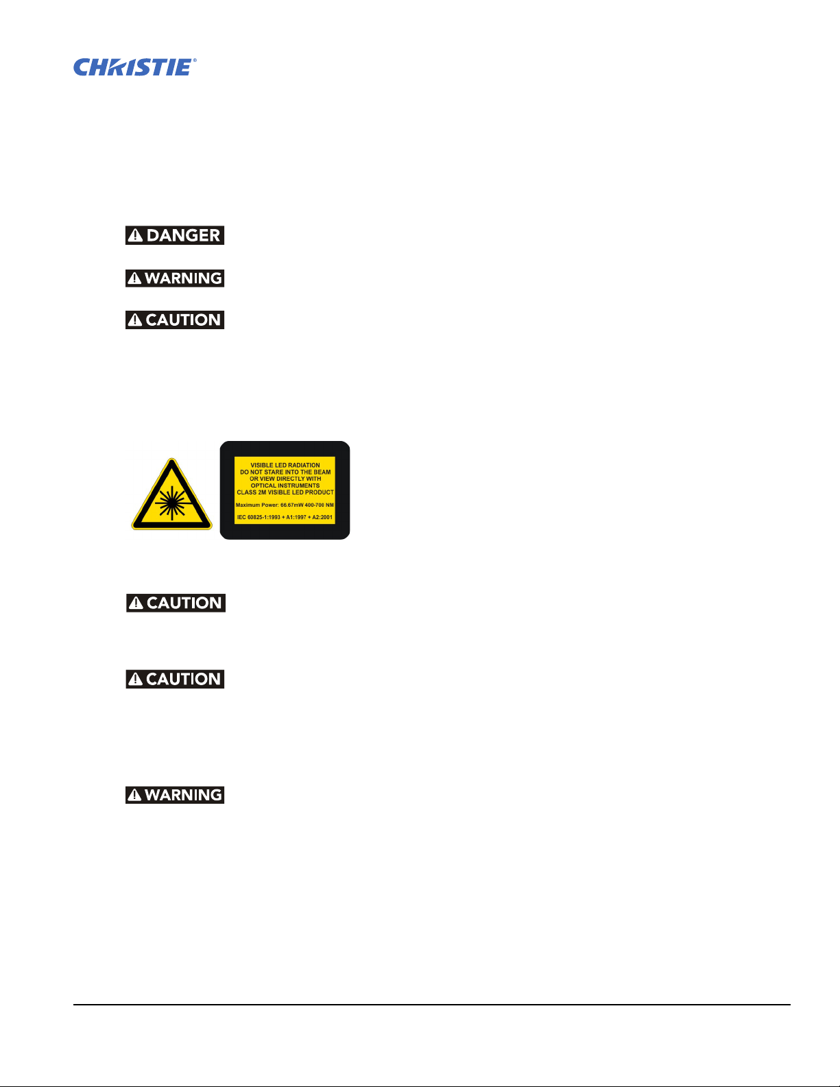
1.1 Labels and Marking
Observe and follow all warnings and instructions marked on the projector.
Danger symbols indicate a hazardous situation which, if not avoided, will result
in death or serious injury.
Warning symbols indicate a hazardous situation which, if not avoided, could
result in dea th or serious injury.
Caution symbols indicate a hazardous situation which, if not avoided, could
result in minor or moderate injury.
NOTICE: Information provided with this heading alerts users to key points of interest not related to personal
injury.
1.2 General Precautions
The projector is a class 2M source of visible and invisible
LED radiation. Directly Viewing the LED output with certain
optical instruments (e.g. eye loupes, magnifiers and
microscopes) within a distance of 100mm (3.94”) may pose
an eye hazard.
The projector is a class 2M source of visible and invisible LED radiation.
Directly viewing the LED output with certain optical instruments (for
example, eye loupes, magnifiers and microscopes) within a distance of 100
mm may pose an eye hazard.
Power should always be disconnected from the illumination module before
servicing, to avoid the possibility of inadvertent exposure to visible and
invisible LED radiation. Directly viewing the illumination module optical
output through certain optical instruments (for example, eye loupes,
magnifiers and microscopes) within a distance of 100mm may pose an eye
hazard.
Disconnect the AC cord before disconnecting the light module from the
Projector Head Module (PHM).
Mirage WU-L User Manual 1-1
020-100774-01 Rev. 2 (4-2012)
Page 14
Section 1: Introduction
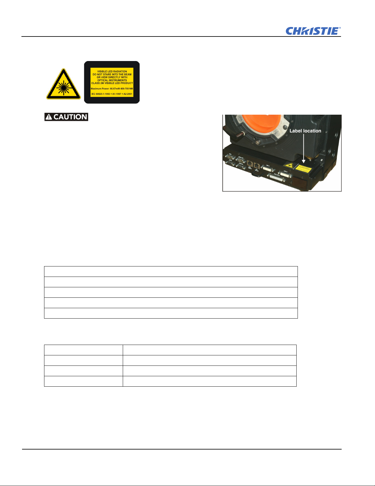
Figure 1-1 LED Caution Label Location
1.3 Safety Warnings and Guidelines
Be aware of the caution label on the projector warning of
possible eye hazard if the projected visible and invisible LED
radiation light is viewed directly through certain optical
instruments at close range. Figure 1-1 indicates where the
label is located.
The projector is a class 2M source of
visible and invisible LED radiation.
Directly viewing the LED output with
certain optical instruments (for
example, eye loupes, magnifiers and
microscopes) within a distance of 100
mm may pose an eye hazard.
1.4 Contacting Your Dealer
If you encounter a problem with your Christie projector, contact your dealer. To assist with the servicing of
your projector, enter the information in the tables and keep this information with your records.
Table 1.1 Purchase Record
Dealer:
Dealer or Christie Sales/Service Contact Phone Number:
Projector Serial Number*:
Purchase Date:
Installation Date:
* The serial number can be found on the license label located on the back of the projector.
Table 1.2 Ethernet Settings
Default Gateway
DNS Server
Projector IP Address
Subnet Mask
1-2 Mirage WU-L User Manual
020-100774-01 Rev. 2 (4-2012)
Page 15
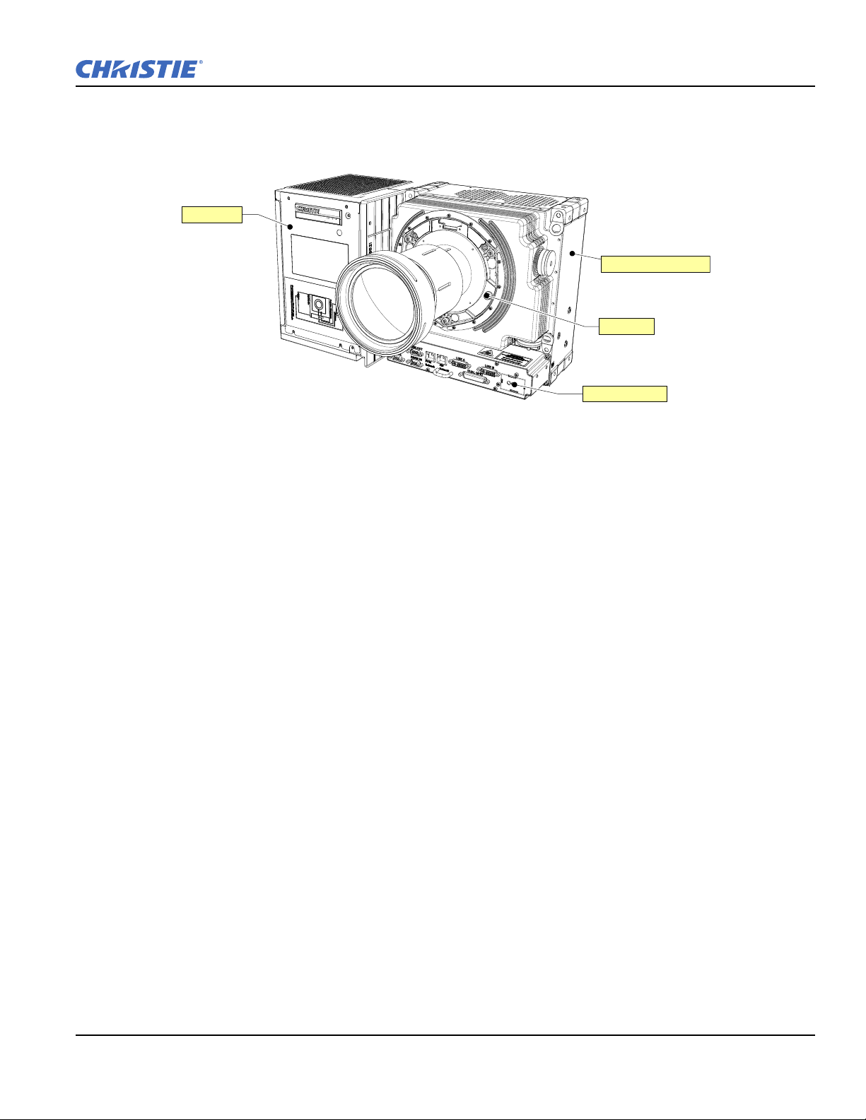
1.5 Projector Overview
Light Module
Projection Head Module
IR Remote Sensor
Lens Mount
Figure 1-2 Mirage WU-L Projector
NOTE: The rubber mount has been removed from around the lens mount for illustration purposes.
1.5.1 Key Features
Section 1: Introduction
• Native WUXGA, 1920 x 1200 resolution
• 10-bit image processing module
• Display of RGB, NTSC, PAL, and SECAM video inputs and HDTV formats
• Edge Blending ability using software for seamless displays
• Dual frequency IR sensor for use with standard IR remote and optional long-range dual frequency remote
• Memory for up to 99 custom “channels” (source setups)
• Intuitive on-screen menu system
• 3D functionality using built-in GPIO port: Native 3D, Frame Doubled 3D, and Dual Input 3D
• LED display for projector status monitoring
• Multiple control options including RS-232 and RS-422
• On-board ChristieNET software
• Universal AC input 100-240 VAC, 50/60Hz
• Dual Image Processing Card (DIPC)
1.5.2 List of Components
Make sure these components were received with the projector:
• Projector Head Module (PHM), with attached Illumination Module (LM)
• Electronics Module (EM)
• Warranty Card
• Web Registration Form
• Line Cord (rated, North American)
NOTE: Each projection system requires a User Kit (P/N: 125-104106-xx). If you did not receive a User Kit or
if you want to purchase additional kits, you can order them separately.
Mirage WU-L User Manual 1-3
020-100774-01 Rev. 2 (4-2012)
Page 16

Page 17

2Installation and Setup
This section explains how to install, connect and optimize the projector display.
2.1 Installation Considerations
• Ambient temperature must stay below 40°C (95°F). Changes in temperature can cause drifts in the projector
circuitry, which may affect performance. Keep the projector away from heating and air conditioning vents.
• Keep the projector away from all devices radiating electromagnetic energy. For example, motors and
transformers, slide projectors, speakers, power amplifiers and elevators.
• Use an optical mirror for rear screen installations to shorten the optical light path and use less space in the
projection room. For more information about projector installations, see 2.1.5 Installation Types.
2.1.1 Ventilation
NOTICE: Caution do not obstruct the air exchange to the projector.
The projector vents provide ventilation, both for intake and exhaust. Do not block or cover these openings. Do
not install the projector near a radiator or heat register, or within an enclosure. Make sure there is a minimum
clearance of 25cm (10”) on the left, right, top and rear sides of the projector.
2.1.2 Screen Size and Type
Screens with an aspect ratio of 16:10 are recommended for use with these projectors. To fill a screen with an
image, the aspect ratio of the screen must be equal to the aspect ratio of the image.
Diffused and optical screens are best suited for rear screen installations. A diffused screen has a surface which
spreads the light striking it. Purely diffused screens have a gain of less than 1. Optical screens take light from
the projector and redirect it to increase the light intensity at the front of the screen.
2.1.3 Ambient Lighting
The contrast ratio of projected images is reduced when light directly strikes the screen. Eliminate all stray light
sources from the viewing area.
Mirage WU-L User Manual 2-1
020-100774-01 Rev. 2 (4-2012)
Page 18
Section 2: Installation and Setup
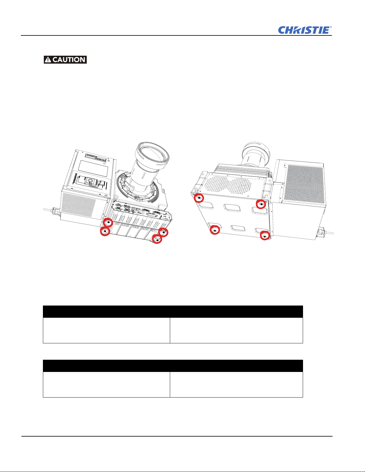
2.1.4 Lifting, Transporting and Mounting
Mount the projector to a sturdy, flat surface that fits the entire projector.
Use all four mounting points to secure the projector to the surface.
Maintain a minimum clearance of 25cm (10”) around the projector, called a
“stay out zone”, for air circulation and clearance for cable connections to the
input panel. Insufficient stay out zone clearance can cause the projector to
overheat during operation and/or place undue stress on source connections.
The projector should be lifted by 2 people. Use a stable cart to transport the projector. Refer to the drawings
given for your specific projector model for the mounting hole location and other technical information and
restrictions which may be useful during
installation.
2.1.5 Installation Types
This topic provides recommendations for getting optimum performance from your Christie projector.
Table 2.1 Front Screen / Floor Mount Installation
Advantages Considerations
• Easy to set up.
• Can be moved or changed quickly.
• Easy to access.
Table 2.2 Front Screen / Inverted Mount (ceiling) Installation
Advantages Considerations
• Does not take up audience space.
• Projector is unobtrusive.
• Projector cannot be accidentally moved.
Figure 2-1 Mounting Holes
• Shares floor space with audience.
• Cannot be moved or changed quickly.
• Access to the projector is limited.
2-2 Mirage WU-L User Manual
020-100774-01 Rev. 2 (4-2012)
Page 19
Table 2.3 Rear Screen / Floor Mount Installation
Advantages Considerations
Section 2: Installation and Setup
• Projector is hidden.
• Projector is easily accessed.
• Good ambient light rejection.
Table 2.4 Rear Screen / Inverted Mount (ceiling) Installation
Advantages Considerations
• Projector is hidden.
• Good ambient light rejection.
Table 2.5 Rear Screen / Floor Mount with Mirror
Advantages Considerations
• Projector is hidden
• Good ambient light rejection.
• Requires less space behind screen than
other rear screen installations.
2.1.6 Rear Installations
There are 2 basic types of rear screen installations:
• Requires a separate room or enclosure.
• Higher installation cost.
• Requires a separate room.
• Higher installation cost.
• Access to the projector is limited.
• Requires a separate room or enclosure.
• Higher installation cost.
• Complex installation.
• A diffused screen has a surface, which spreads the light striking it. Purely diffused screens have a gain of less
than 1.0. The advantage of the diffused screen is its wide viewing angle, similar to that of a flat screen for
front screen projection. This type of screen is suitable when a wide viewing angle is required but there is low
ambient room lighting.
• Optical screens take light from the projector and redirect it to increase the light intensity at the front of the
screen. This reduces it in other areas. A viewing cone, similar to that of a curved front screen installation is
created. This type of screen is better suited for brightly lit rooms where the audience is sitting within the
viewing cone.
Mirage WU-L User Manual 2-3
020-100774-01 Rev. 2 (4-2012)
Page 20
Section 2: Installation and Setup
Interconnection Diagram
Electronics Module
Projection Head Module
Light Module
Shown in lens-vertical configuration (top view)
Same connections for lens-horizontal conf iguration
Link A
EM Network
EM Power
EM Network
EM Power
Link A
Link B
Link B
Figure 2-2 Module
Interconnections
2.2 Installing the Projector
This section gives the installation sequence for the Mirage WU-L projector.
2.2.1 Unpacking the Projector
The projector is shipped assembled with the projection lens shipped separately.
The lens must be installed prior to setting up the projector.
1. Remove the projector from the box and packing material.
NOTE: Save packing material for at least 1 projector in case a projector needs to
be shipped for service.
2. Connect the Electronics Module to the Projector Head Module and Light Module.
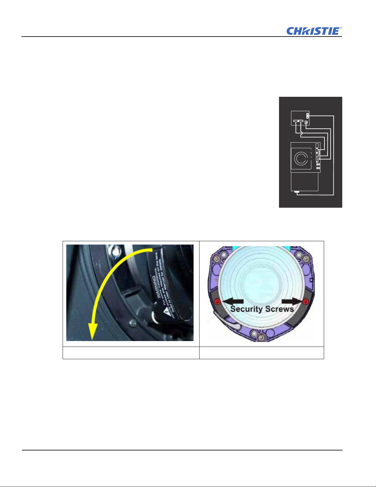
2.2.2 Installing the Lens
1. Remove the rear lens cap from the lens. Keep the front lens cap on the lens.
2. Rotate the lens clamp to the OPEN position (Figure 2-3).
Figure 2-3 Rotate to Open Figure 2-4 Security Screws
3. Remove and retain the (2) security screws from the lens mount, see Figure 2-4.
4. Align the lens interface plate with the lens mount. Fully insert the assembly straight into the lens mount
opening without turning.
NOTICE: Ensure the lens IS NOT inserted at an angle as this can cause damage.
5. Rotate the lens clamp to the CLOSED position before fastening the security screws.
6. Fasten the security screws (Security Screws).
NOTICE: Security screws MUST be installed.
7. Remove the front lens cap.
For more information concerning lenses, see 2.11 Projection Lenses, Lens Mount and Other Features and
2.12 Cleaning the Lens.
2-4 Mirage WU-L User Manual
020-100774-01 Rev. 2 (4-2012)
Page 21
Section 2: Installation and Setup
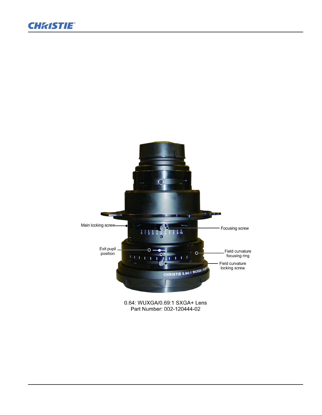
Lens Focus Adjustment for Fixed Lenses
This section describes best practices for lens focus adjustment of the 0.64:1 WUXGA lens
(PN: 002-120444-02) and the 0.75:1 (PN: 002-120415-01). The lenses have focus and field curvature
correction to sharpen the projected image. Failure to properly adjust lens focus results in an image that is not
uniformly focused and contains geometric distortion.
1. Loosen the main locking screw and the focusing screw.
2. Adjust the focusing screw for best focus in the image center.
3. Loosen the field curvature locking screw and adjust the field curvature focusing ring to sharpen the image
corners. Refer to the image below as an aid to gage the specific preset for your screen size.
4. Finally the focus screw should be "tweaked" for best overall screen focus.
5. Although it is not necessary, you may want to retighten the main locking screw. NOTE: Use a maximum of
4in.-lbs to tighten the main locking screw.
Figure 2-5 0.64:1 WUXGA Lens
Mirage WU-L User Manual 2-5
020-100774-01 Rev. 2 (4-2012)
Page 22
Section 2: Installation and Setup
Throw Ratio
throw distance
screen width
-----------------------------------
2%=
% Offset
# of pixels of offset
half vertical panel resolution
--------------------------------------------------------------------
100=
2.2.3 Calculating Throw Distance, Position and Mount Projector
Throw distance is the distance measured from your projector to the screen. This calculation determines if there
is enough room to install your projector with a desired screen size and if the image will be of the right size for
your screen. To estimate the throw distance take the horizontal width of the screen and multiply it by the lens
throw ratio. The result determines approximately the distance the projector should be positioned from the
screen to project a focused image large enough to fill the screen. For example, using a 1.2:1-1.6:1 zoom lens
set at its widest (1.2:1) throw ratio, throw distance would roughly be 1.2 x screen width.
IMPORTANT: Use the lens and screen size to calculate the precise throw distance. Due to lens manufacturing
tolerances for lens focal length, actual throw distance can vary
throw ratio.
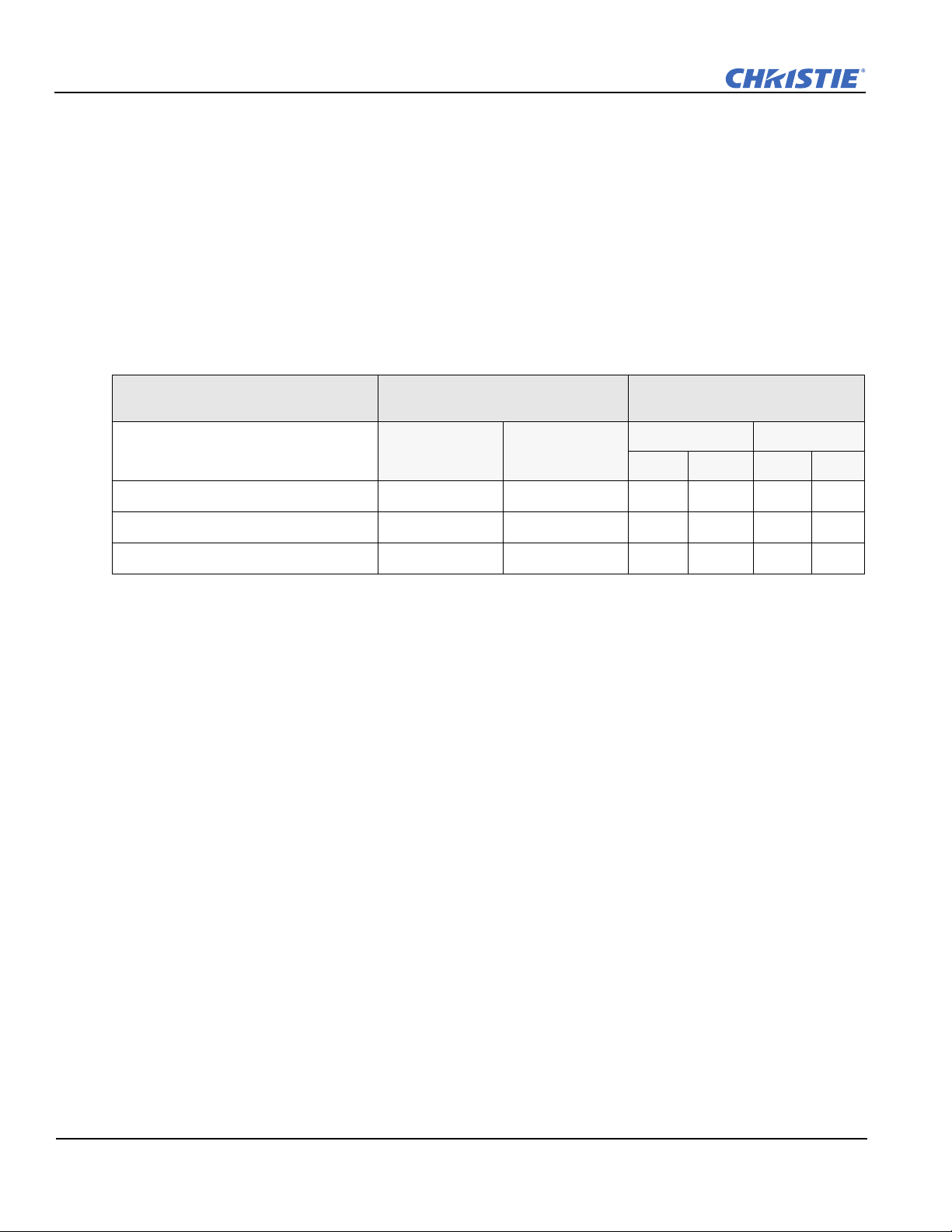
Table 2.6 Lens Types, Offsets and Throw Distances
±2% between lenses with the same nominal
CHRISTIE Lens
Throw Distance
Offset Percentage (Offset Pixels) Specified Throw Distance
Range
Horizontal Vertical Inches Meters
Min Max Min Max
0.64:1 11% (211) 26% (312 px) 40 120 1.0 3.1
1.2-1.6 75% (1440) 150% (1800 px) 59 213 1.5 5.4
0.75:1 75% (1440) 134% (1608 px) 28 102 0.7 2.6
NOTES:
Offsets are subject to ±7% centering tolerance.
1)
2) Image size outside the specified width range may result in reduced image quality.
3) Throw distance is measured from the marked exit pupil position on the lens (see Figure 2-5) to the screen.
Throw ratio is defined as:
4) 100% offset is defined as having all pixels shifted beyond the axis.
5) Offsets are measured from optical lens centre, which may not coincide with mechanical centre % offset is
defined as:
2-6 Mirage WU-L User Manual
020-100774-01 Rev. 2 (4-2012)
Page 23
Section 2: Installation and Setup
% Offset
# of pixels of offset
half vertical panel resolution
--------------------------------------------------------------------
100=
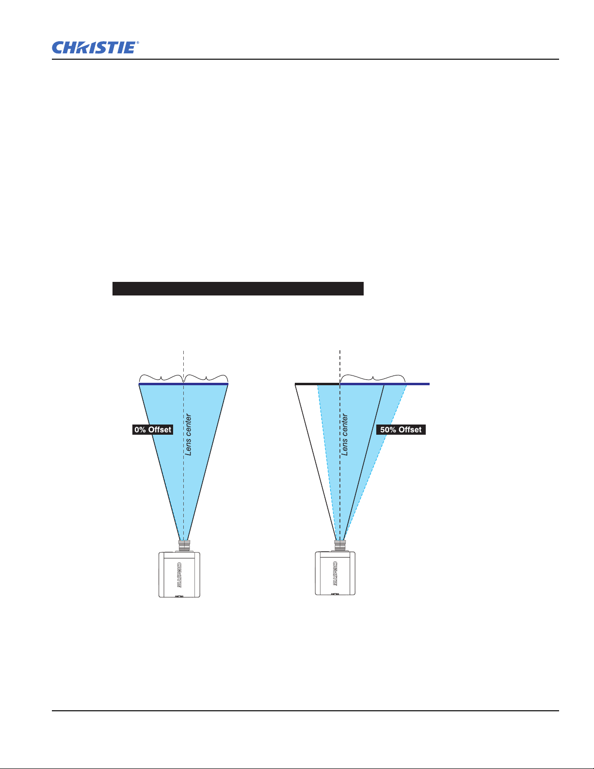
d; therefore,
half of the image appears to the left or lens center
#2 In this example, 50% offset is applied; therefore,
3/4 or 75% of the image appears to the one side of
Shaded area = projected image
960 pixels
display to left
of lens center
960 pixels
display to right
of lens center
480 pixels to
left of lens
center
1440 pixels displayed
to right of lens center
or 480 pixels of shift
to right of lens center
Example of Horizontal Offset (WUXGA pixels represented)
Projector Vertical and Horizontal Position
The projection lens and the screen type determine the vertical and horizontal position of your projector in
relation to the screen. Ideally, you should position the projector perpendicular to the screen to make the image
appear rectangular instead of keystoned (trapezoidal). You can offset vertical position of the image (move it
above or below the optical axis) by adjusting the lens mount. The type of projection lens you install determines
the amount of available vertical offset. Vertical offset can be expressed as the percent of half the image height
or the number of pixels of shift from lens center.
NOTES:
1)
Offsets are subject to ±7% centering tolerance.
2) % offset is defined as:
The horizontal position of the image can also be offset (moved to the left or right of optical center) by adjusting
the lens mount. The amount of horizontal offset available depends on the lens installed and if the image has
already been vertically offset. Horizontal offset can be expressed as the percent of half the image width or the
number of pixels of shift to one side of lens center.
#1 In this example, no offset is applie
and half appears to the right.
the lens center.
Mirage WU-L User Manual 2-7
020-100774-01 Rev. 2 (4-2012)
Page 24

Section 2: Installation and Setup
Mounting the Projector
NOTICE: Use only the CHRISTIE approved projector mounts designed for your projector. Refer to the
installation instructions and safety guidelines provided with in the kit.
There are several methods for mounting the projector. In typical front and rear screen installations the projector
can be mounted to a secure and level surface. The projector can be mounted in any orientation without
affecting performance.
2.3 Connecting Sources
All source connections are made to the input panel of the Electronics Module. Each input is labeled for easy
identification. Using the correct cable(s), connect your source. An interconnection label is available for
reference on the light module. Sources are connected to the Input Panel located at the top of the EM. The Input
Panel has slots for 1 image processor board and up to 4 input cards, and comes standard with 2 slots populated.
The input cards are hot swappable; they can be plugged in and out while the projector is running. The image
processor should only be replaced when the projector is OFF or when it is in STANDBY mode.
The video card that is installed in your projector determines the type of video source you can use. These video
cards are supported:
• High-Definition Multimedia Interface/Twin HDMI (High-Definition Multimedia Interface)
• Analog BNC
• Dual SD/HD-SDI (Serial Digital Interface)
• Dual Link DVI
•Video Decoder
These cards slide into any of the available option slots. One or more of the option slots may be used with any
combination of option cards, including multiples of the same card type. One input is active on any card at a
single time, except the Dual HDMI and Dual SD/HDSDI cards, which support up to 2 active signals on 1 card.
NOTE: Use only high-quality shielded cables for all connections.
LEDS
LEDs are located on the faceplate of each input card and indicate the following:
• Power ON - Green
• Signal Valid - Green
• Signal Invalid - OFF
DVI Digital Video
Use the DVI-I connector to connect either analog or digital video devices to the projector. Use a cable with
DVI-I connectors at both ends to connect devices that transmit digital and analog video signals such as satellite
receivers and digital cable TVs.
NOTE: For true digital output from devices that transmit digital signals,
connect to the DVI-I connector.
2-8 Mirage WU-L User Manual
020-100774-01 Rev. 2 (4-2012)
Page 25
Section 2: Installation and Setup
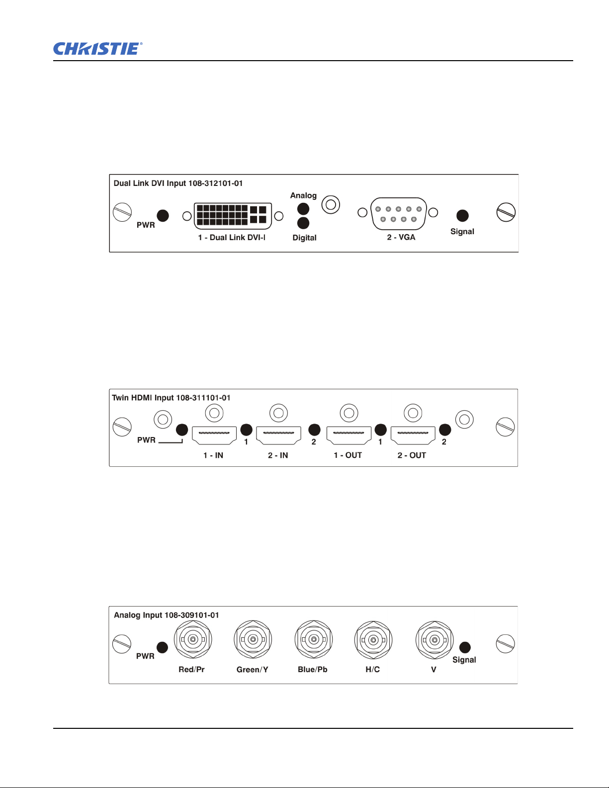
Dual Link Digital Video Input (DVI) Input Card
This card accepts a maximum 330MHz DVI-D or 165MHz HDMI signal via the DVI-I connector without
High-Bandwidth Digital Content Protection (HDCP) and analog video signals over the DVI-I or 15-pin VGA
connector. The module can simultaneously support a digital signal on the DVI input and an analog signal on
the VGA port; however, it does not support 2 analog signals at the same time. There are 4 LEDs on the module
faceplate. PWR indicates power is applied and the card is initialized, and the other 3 LEDs on the right-side of
the corresponding connectors indicate that a valid signal has been detected.
Twin HDMI Input Card
This card accepts 1 or 2 HDMI inputs, and can route one or both inputs to the card’s outputs without HighBandwidth Digital Content Protection (HDCP). Any input from any card can be looped out of this card. The
output label ‘1-OUT’ loops out the main image being displayed on the projector. The output labelled ‘2-OUT’
loops out the image displayed in the picture in picture (PIP). Any input from any optional input card can be
looped out of this card. There are five LEDs on the module faceplate. The PWR on the left side indicates
power is applied, and that the card is initialized. The LEDs to the right side of the corresponding connectors
indicate that a valid signal is detected. In the case of the outputs, the LED indicates a signal is currently being
looped out.
Analog BNC Input Card
This card accepts several types of sync modes. In 5-wire sync mode all 5 BNC connectors are used. If H and V
connectors are swapped, this card will still operate normally. An analog graphic source such as a VGA from a
PC can be connected. The card can operate in 4-wire sync mode, which accommodates 4-wire RGBC sources.
The composite sync cable can be connected to either the H/C BNC or the V BNC. The card supports 3-wire
RGB or YPBPr sync modes, sometimes called sync-on-Green (SOG). In this mode the H/C and V connectors
are not used. The sync is connected to the Green/Y BNC connector. This card offers no loop out capability.
There are 2 LED’s on the module faceplate. PWR indicates power has been applied and the card is initialized,
signal indicates a valid signal has been detected.
Mirage WU-L User Manual 2-9
020-100774-01 Rev. 2 (4-2012)
Page 26
Section 2: Installation and Setup
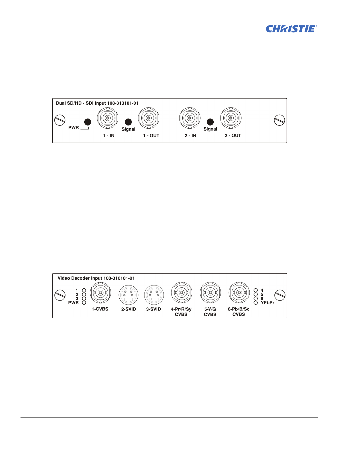
Dual SD/HD - SDI Input Card
This card accepts both standard-definition (SD) and high-definition (HD) serial-digital-interface (SDI) signals
from one of two standard-definition (SD) or high-definition (HD) SDI sources. Both single-link HD and duallink HD signals are accepted. The card has two SD/HD-SDI outputs, each of which is “loop through” for its
respective input. There are three LEDs on the module faceplate. PWR indicates power has been applied and the
card is initialized, and the two signal LEDs indicate a valid signal has been detected on the respective input.
Video Decoder Input Card
This card accepts and decodes standard definition (SD) video. This includes CVBS (composite video), SVideo, and component sources. This card supports as many as six video signals, four of them on BNC
connectors and two on four-pin mini-DIN connectors. Each mini-DIN connector accepts one S-Video signal.
The first BNC accepts composite video (only), while the remaining three BNCs can be grouped to allow one of
the following combinations:
• 3 CVBS sources on 4, 5 & 6
• 1 CVBS source, 1 S-Video source: Luma (Y) connected to 4 (Sy) and Chroma (C) connected to 6 (Sc)
• 1 YPbPr source: component signal on 4(Pr), 5(Y) & 6(Pb)
The video decoder input card has 8 LED indicators. The PWR LED indicates that the module is installed
properly, and has been successfully configured. The YPbPr LED indicates that a valid component signal has
been detected on inputs 4, 5, and 6 (Component input grouping must also be selected in the projector’s menu see Section 3 Operation. The remaining LEDs are each associated with one of the inputs and indicate a valid
signal has been detected on that input.
2-10 Mirage WU-L User Manual
020-100774-01 Rev. 2 (4-2012)
Page 27

2.4 Power Connection
The projector is a class 2M source of visible and invisible LED radiation.
Directly viewing the LED output with certain optical instruments (for
example, eye loupes, magnifiers and microscopes) within a distance of 100
mm may pose an eye hazard
Do not operate if the AC supply and cord are not within the specified
voltage and power range. The North American rated line cord is supplied
with this projector. For all other regions, use only a regionally approved line
cord, power plug and socket. Do not use a damaged line cord.
2.4.1 Connecting the projector to AC
The input voltage to the projector must be capable of 100-240 VAC. Use only a correctly rated line cord.
NOTE: Do not use a line cord or AC supply not in the specified voltage and power range. See Section 7
Specifications for projector power requirements.
1. Connect an approved line cord to the projector AC receptacle, located on the Light Module. Use only the
line cord supplied with the projector or a power cord of correct ratings that comply with regional
standards.
Section 2: Installation and Setup
2. Connect the 3-pronged end of the line cord to a grounded AC outlet. The outlet must be near the equipment
and easily accessible.
2.4.2 Turning the Projector ON
1. Flip the power switch on the LM (Light Module) ON. The projector takes about 2 minutes to initialize.
The status light beside the LED window turns yellow.
NOTE: The Electronics Module has a circuit breaker which is generally left ON. Certain error conditions
can turn the circuit breaker off. The circuit breaker must be ON for proper projector function.
2. Using the remote keypad, press the Power button, and then the UP arrow.
3. Press one of the input keys on the remote to select and display the image for the source connected in
2.3 Connecting Sources. For more information on the key functionality, see 3.1.1 IR Remote, on page 3-2.
For more information about sources, see 2.3 Connecting Sources, on page 2-8.
2.4.3 Disconnecting the projector from AC
Do not turn the main power switch to the OFF position or disconnect the
projector until the cooling fans have stopped.
1. Stop the projector.
2. After the internal cooling fans stop, move the main power switch on the light module to the OFF position.
3. Disconnect the line cord from the wall outlet.
Mirage WU-L User Manual 2-11
020-100774-01 Rev. 2 (4-2012)
Page 28
Section 2: Installation and Setup
2.5 Communicating With the Projector
To use the remote control, point the remote at the display screen or the projector IR sensor. To use the remote
with the cable, connect the cable to the remote and to the connector labeled
REMOTE on the Electronics Module
input panel. Check Wired Keypad Enabled in the Communications menu.
As an alternative to the projector keypad or remote, communicate with the projector using a PC or other
controller. Commands and feedback are sent to the projector's Electronics Module using Ethernet or serial links
(RS232 and RS422).
NOTE: Do not connect to the Projector Head Module (PHM).
2.6 Projector Network Setup for External Communication
This section outlines a several ways to set up a Mirage WU-L projector network for external communication.
IMPORTANT: To complete the projector network setup you will also need to connect the projectors together for
arrayLOC communication and functions. See ArrayLOC Network on page 3-53.
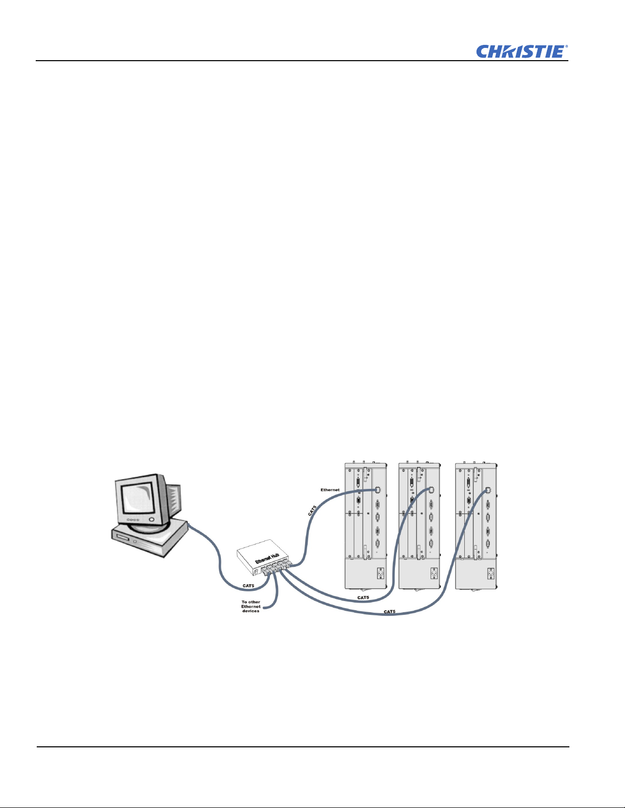
2.6.1 Ethernet (Recommended)
In the Ethernet network the controller communicates with each projector separately.
To add a projector to an Ethernet network:
1. Connect a standard CAT5 Ethernet cable between the controller (or Ethernet hub) and the Ethernet port on
the projector Electronic Module.
2. Set the IP address in Configuration > Communications > Ethernet Settings. See Ethernet Settings on
page 3-34.
3. Set Configuration > Communications > Network Routing to Separate. See Network Routing on
page 3-33.
2-12 Mirage WU-L User Manual
020-100774-01 Rev. 2 (4-2012)
Page 29
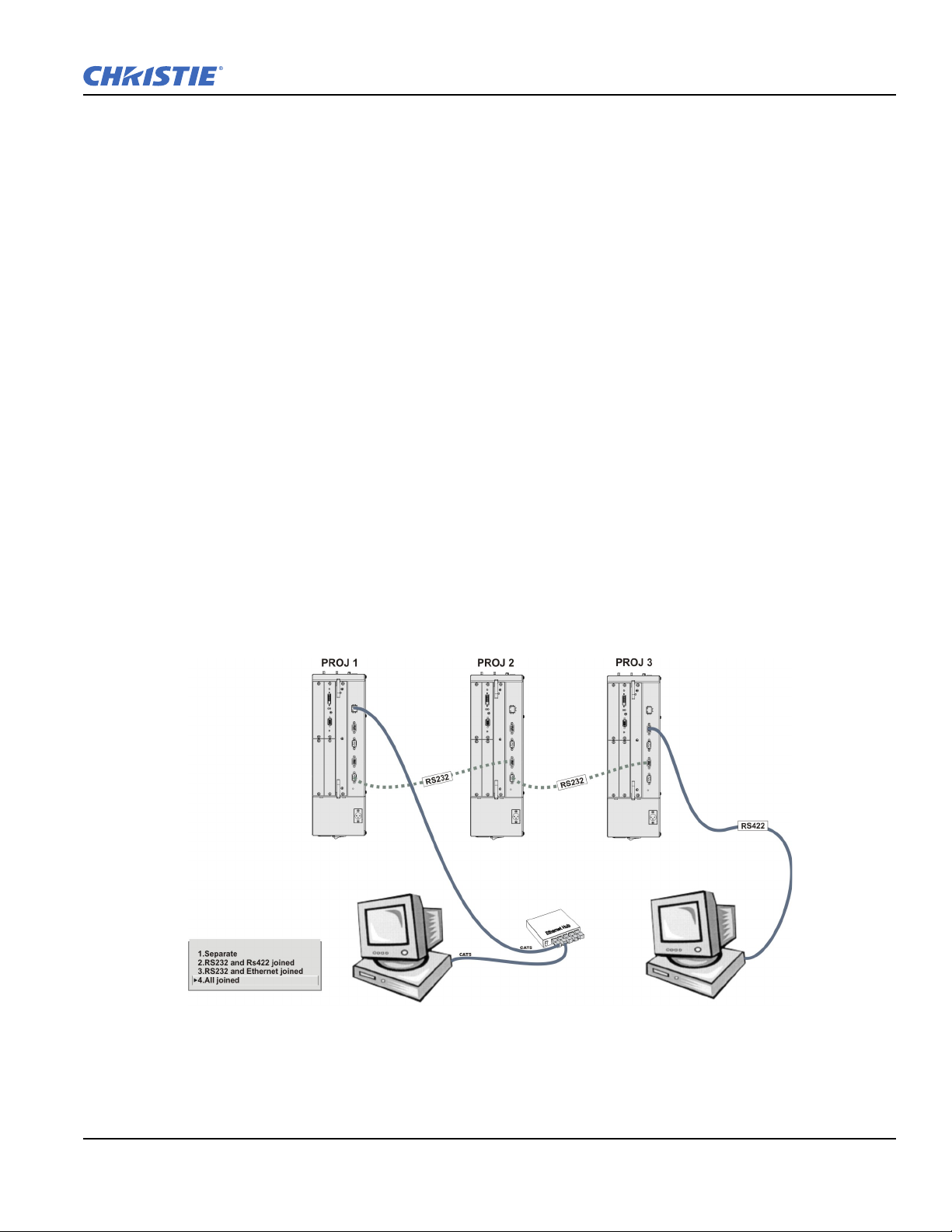
2.6.2 Mixed Network
In the mixed network the controller can communicate with the first projector and the command can be relayed
to each serially connected projector. This configuration is useful if you are using a non-RS232 controller with
the RS232 linking available between these projectors. The example shows both an RS422-compatible
controller and an Ethernet-connected PC for working with a network of projectors linked using their RS232 in/
out ports.
• Connect the controller to one projector:
• A standard CAT5 Ethernet cable between the controller (or Ethernet hub) and the Ethernet port on the
Electronic Module
• An RS-422 serial cable between the PC and the RS422 IN (pictured).
Section 2: Installation and Setup
• Connect a serial cable between the RS232 OUT connector of the first projector
Electronics Module and the
RS232 IN connector of the next projector Electronics Module. Connect the remaining projectors. RS232
communication cables must be good quality and no more than 25 feet in length.
• If you connected the controller, using an Ethernet cable, set the IP address in Configuration >
Communications > Ethernet Settings. See Ethernet Settings on page 3-34.
• Set the serial options in Configuration > Communications. See Communications on page 3-32.
•Set Configuration > Communications > Network Routing. See Network Routing on page 3-33.
• To relay commands to all projectors set Network Routing to All Join.
• To isolate just RS422 communications, select RS232 and Ethernet Joined. Only projector #3 will
respond to the RS422 controller.
• To isolate just Ethernet communications, select RS232 and RS422 Joined—only projector #1 will
respond using Ethernet.
Mirage WU-L User Manual 2-13
020-100774-01 Rev. 2 (4-2012)
Page 30
Section 2: Installation and Setup
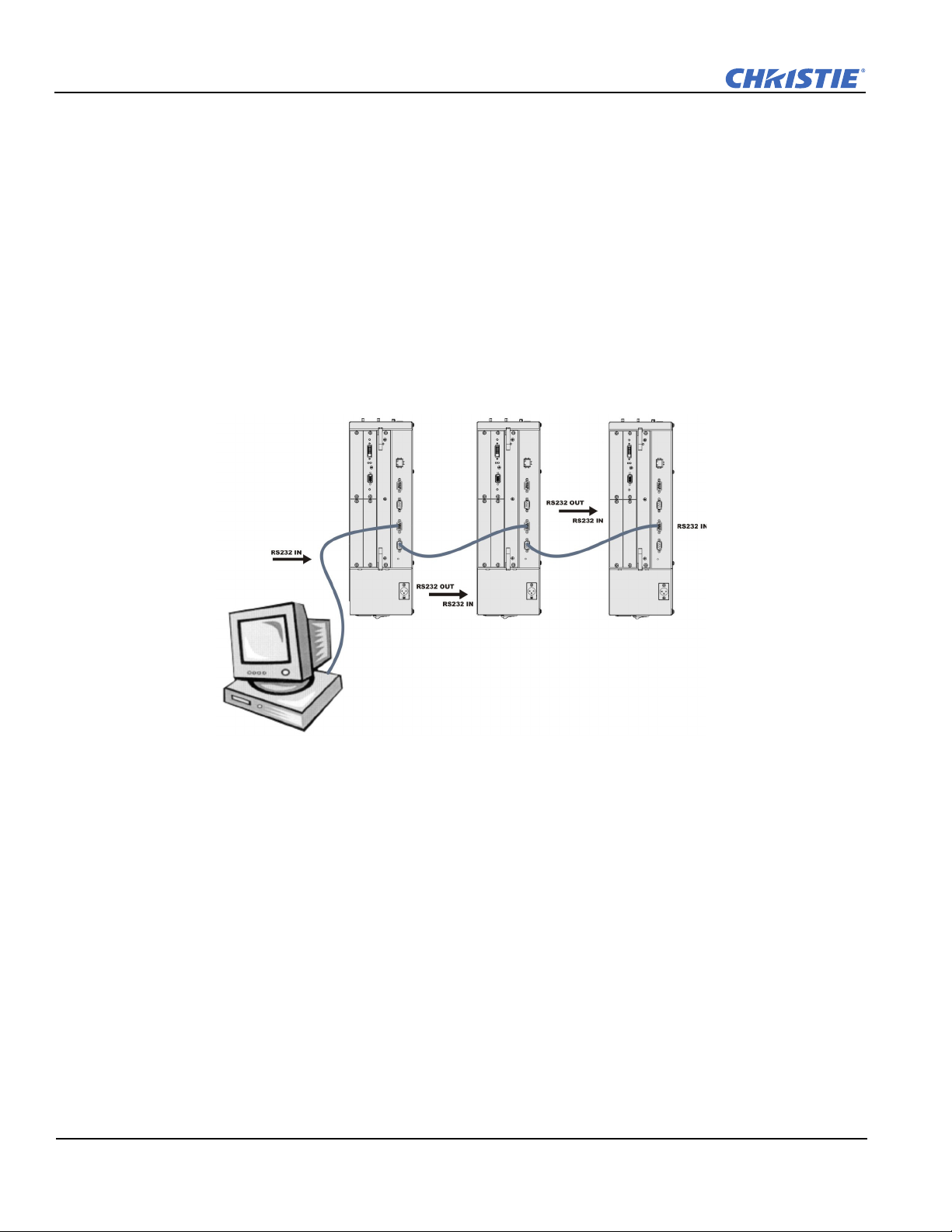
2.6.3 RS-232 Network
In the RS-232 network the controller can communicate with the first projector and the command can be relayed
to each serially connected projector.
• Connect the controller to one projector using serial cable between the PC and the RS232 IN port on the
Electronic Module.
NOTICE: Using the wrong type of serial cable can damage the projector.
• Connect a serial cable between the RS232 OUT connector of the first projector
Electronics Module and the
RS232 IN connector of the next projector Electronics Module. Connect the remaining projectors. RS232
communication cables must be good quality and no more than 25 feet in length.
• Set the RS-232 serial options in Configuration > Communications. See Communications on page 3-32.
•Set Configuration > Communications > Network Routing to one RS232 and RS422 Joined. See Network
Routing on page 3-33.
2-14 Mirage WU-L User Manual
020-100774-01 Rev. 2 (4-2012)
Page 31

Section 2: Installation and Setup
Mixed Serial Network (RS-232 and RS-422)
RS-422 serial communication is better over long distances than RS-232 communication. Use the RS-422 port
only if your device has RS-422 capability. Always read the equipment literature before connecting.
NOTICE: Connecting to the RS-422 port with incompatible equipment, including the wrong type of serial cable,
can damage the projector.
In the RS-422 network the controller can communicate with the first projector and the command can be
relayed to each serially connected projector.
• Connect the controller to one projector using RS-422 serial cable between the PC and the RS-422 IN port on
the Electronic Module.
• Connect an RS-232 serial cable between the RS232 OUT connector of the first projector
Electronics Module
and the RS232 IN connector of the next projector Electronics Module. Connect the remaining projectors
using RS232 cables. RS232 communication cables must be good quality and no more than 25 feet in length.
• Set the serial options in Configuration > Communications. See Communications on page 3-32.
•Set Configuration > Communications > Network Routing to one RS232 and RS422 Joined. See Network
Routing on page 3-33.
Mirage WU-L User Manual 2-15
020-100774-01 Rev. 2 (4-2012)
Page 32

Section 2: Installation and Setup
2.7 Projector Network Setup for ArrayLOC Communication
See the Integration Guide for detailed information about arrayLOC setup.
2.8 Setting up the Image
2.8.1 Adjusting the Projection Lens
NOTICE: Lock lens adjustments to prevent unnecessary tampering.
Loosen the adjustment locks on the lens barrel before making adjustments.
2.8.2 Adjusting Image Geometry and Optical Alignment
Only perform image alignment once the projector is fully assembled and powered up in its final location. Basic
image alignment ensures the image reflected from the DMD is parallel to and well-centered with the lens and
screen. This initial optical alignment is the foundation for optimizing images on the screen, and must be
completed before final boresight adjustments. Before beginning, ensure that the projector is properly
positioned relative to the screen.
Basic Optical Alignment Procedure
1. Display a test pattern: Appropriate for analyzing image focus and geometry, such as the “framing” test
pattern showing the cross-hair centered across the image. Press the Test key on the remote keypad.
2. Coarse focus: Do a quick preliminary focus and (if available) zoom adjustment with the primary lens. Do
not worry about consistency across the image at this point, just center focus. It is good practice to have the
zoom adjustment collar and the focus adjustment collar in the center of its range.
3. Center the image in the lens: Holding a piece of paper at the lens surface, adjust offsets as necessary until
the image is centered within the lens perimeter. A full white field works best for this.
4. If necessary, center the image on the screen: If the projector is mounted off-center to the screen axis,
then offset the lens as much as required. Aim the projector over slightly towards the center of the screen,
but use caution, as too much tilt will cause excessive keystone distortion. Lens offset will not.
5. Re-check side-to-side leveling: With the framing pattern on screen, double-check projector leveling so the
top edge of the image is parallel to the top edge of the screen.
6. Throw distance: Ensure that the projector is positioned in the throw distance range for the lens in use.
2-16 Mirage WU-L User Manual
020-100774-01 Rev. 2 (4-2012)
Page 33

Folded Optics
Figure 2-6 Folded Optical Path
Figure 2-7 Boresight Pattern
In rear screen applications where space behind the projector is limited, a mirror may be used to fold the optical
path, see Figure 2-6. The position of the projector and mirror must be accurately set - if considering this type
of installation contact Christie Customer Support for assistance.
2.8.3 Boresight Alignment (Advanced)
Section 2: Installation and Setup
1. Display the Boresight Test Pattern by pressing the Tes t key on the remote keypad, then use the Left arrow
key to cycle to Boresight, see Figure 2-7.
2. Focus the image on the cross-hair pattern at the image center. Evaluate the focus on cross-hair image I and
II. If all three images are in focus, no further action is required. If boresight is required see step 3.
Mirage WU-L User Manual 2-17
020-100774-01 Rev. 2 (4-2012)
Page 34

Section 2: Installation and Setup
Figure 2-10 Position Setscrew Flush
3. If boresight is required, see Figure 2-8 to understand how the adjustment screws on the lens mount affect
the corresponding cross-hairs on the test pattern.
4. Use a 5mm Allen key to loosen the three locking setscrews on the lens mount, see Figure 2-9.
NOTE: The setscrews must be backed out several turns, so that they do not contact the inner lens mount
plate.
Figure 2-8 Cross-Hair Pattern Figure 2-9 Screw Locations
5. Fine tune the focus of cross-hair pattern I by adjusting the appropriate capscrew, see Figure 2-9. Adjust
until the cross-hair image is in focus with minimal flare.
6. Adjust cross-hair pattern II, by adjusting the appropriate capscrew, see Figure 2-9. Adjust until the crosshair image is in focus with minimal flare.
7. Adjust cross-hair pattern III, by adjusting the
appropriate capscrew, see Figure 2-9. Adjust until the
cross-hair image is in focus with minimal flare.
8. Repeat steps 5, 6 and 7 as required until all three crosshair patterns are in equal sharp focus. If the boresight is
acceptable, see Step 11. If the boresight does not appear
to be converging to an acceptable level of image quality
or if the lens will not focus over the correct range of
throw distances, then the boresight requires coarse
adjustment, see step 9.
9. The original factory boresight can be recovered
approximately by positioning the 3 setscrews, see
Figure 2-9. Position the setscrews flush with the front face of the lens mount plate and in contact with the
inner lens mount plate, see Figure 2-10. This may require adjusting both setscrews and capscrews.
10. If further action is required. Repeat step 2.
2-18 Mirage WU-L User Manual
020-100774-01 Rev. 2 (4-2012)
Page 35

11. Lock the set screws and re-check the boresight quality. Tighten the setscrews enough to ensure they will
not shift.
12. When the image is focused, lock adjustments in place by tightening the adjustments until just tight.
2.9 Adjust software to Optimize Image
NOTES: 1) See Section 3 for details on accessing and adjusting individual settings. 2) Unless otherwise
indicated, instructions apply to all projector models in stand-alone or multi-projector configurations.
1. Display an external signal.
2. Select Screen Image Orientation in Configuration > Output Options and change the orientation of the
displayed image to suit the installation.
3. Assign projector ID number(s).
4. Modify options in the Main menu. For example, select Language to change the menu language.
5. Enable Broadcast Keys in the Communications menu – this lets you to switch between communicating
with one or all projectors when connected serially.
6. Select Auto Setup to automatically select the best settings for an incoming signal.
7. Make sure that Processing Mode, in Image Settings, is correct for the selected source.
Section 2: Installation and Setup
8. Change Resize Presets if you want the image displayed at a resolution other than native.
9. Adjust Pixel Phase and Pixel Tracking from the Size and Position menu to eliminate noise from the
displayed image.
10. Adjust H-Position and V-Posi tion from the Size and Position menu to re-center the image on screen.
11. Adjust Size in Size and Position until the image is at the necessary width, then adjust Ve r ti c al St r et c h.
Adjusting one option may have an affect on the other; repeat adjustment if necessary. Adjust H-Position
and V-Position again if required to center the image.
12. Adjust the geometry. Use Tabl e 2. 7 as a guide.
Table 2.7 Recommended Order for Image Setup
Flat, Straight-forward Alignment
(Use the options available in
Menu > Configuration > Geometry and Color)
Geometry Correction TWIST™ Software - Warping
Edge Blending TWIST™ Software - Blending
Black Blending
Brightness Uniformity TWIST™ Software - Brightness Uniformity
(Use TWIST software for geometry correction
and blending, see the TWIST User Manual)
NOTE: Do not use black blending if Twist software is
used for geometry correction.
Complex Geometry
13. ArrayLOC automatically adjusts projector colors and brightness. Ensure that arrayLOC is enabled.
14. Some analog sources may require adjustments to Blacklevels and Input Levels.
Mirage WU-L User Manual 2-19
020-100774-01 Rev. 2 (4-2012)
Page 36

Section 2: Installation and Setup
GPIO
12637485
9
2.10 System Integration - GPIO Connector
The General Purpose Input-Output (GPIO) connector located on the Mirage WU-L projector input panel is
used to enable control of stereo function.
GPIO and External Devices
If you want to use GPIO to interface external I/O devices to the Mirage WU-L projector, you will need to have
a custom adapter made. Seven GPIO pins on the 9-pin D-Sub GPIO connector are configured through RS232
commands. The other two pins are reserved for ground and power. See GPIO Pins for pin identification. The
cable required for connecting the external device to the projector GPIO connector, whether a standard serial
cable or a custom one, must be compatible with the external device.
Table 2.8 GPIO Pins
PIN NUMBER SIGNAL
1 + 12V (200mA)
2GPIO 1
3GPIO 2
4GPIO 3
5 Ground
6GPIO 4
7GPIO 5
8GPIO 6
9GPIO 7
The GPIO connector can be configured to automate any number of events using the serial command code GIO.
Each pin is defined as either an input or output depending on the desired outcome. In general, configure the pin
as an input if you want the projector to respond to something the device does and as an output if you want the
external device to respond to an action taken by the projector. For example, configure the pin as an output if
you want the lighting in a room to automatically dim when the projector is powered ON. By using the GIO
command, you can also set the state of each pin as high or low. By default, the state of each pin is high. The
voltage applied to pins in the high state is + 3.3V. See (GIO) General Purpose Input/Output, on page D-29.
2.11 Projection Lenses, Lens Mount and Other Features
Using the lens cap when transporting the lens avoids scratching and
damaging the lens.
The Mirage WU-L projector includes a lens mount that allows lens control and adjustment: vertical and
horizontal offsets, zoom and focus. The lens mount can be fitted with any one of the available optional lenses –
see Section 7 Specifications.
• Zoom and Focus – Adjust zoom to fit the displayed image on the screen and adjust focus to improve the
clarity of the image.
• Lens Offset – The lens mount allows vertical and horizontal offset of the displayed image.
• Shutter – Standard on all models, the shutter allows you to turn the screen absolutely black when in the
“Closed” state. A WHITE shutter state allows you to view menus and images if RGB brightness is set to 0.
2-20 Mirage WU-L User Manual
020-100774-01 Rev. 2 (4-2012)
Page 37

2.12 Cleaning the Lens
Check periodically. A small amount of dust or dirt on the lens has minimal effect on image quality. To avoid
the risk of scratching the lens, clean only if absolutely necessary.
Dust:
1. Brush most of the dust from the lens with a camel-hair brush or blow dust away with a dust-free blower.
2. Fold a microfibre cloth smooth and gently wipe remaining dust particles from the lens. Wipe evenly with
the smooth portion of the cloth that has no folds or creases. DO NOT apply pressure with your fingers - use
the tension in the folded cloth itself to collect dust.
3. If significant dust is still bound to the surface, dampen a clean microfibre cloth with coated optics cleaning
solution (damp, not dripping). Wipe gently until clean.
Fingerprints, smudges, or oil:
1. Brush away most of the dust with a camel-hair brush and/or blow away using a dust-free blower.
2. Roll a lens tissue around a swab and soak it in coated optics cleaning solution. The tissue should be damp,
but not dripping.
3. Gently wipe the surface using a figure-8 motion. Repeat this motion until the blemish is removed.
Section 2: Installation and Setup
Mirage WU-L User Manual 2-21
020-100774-01 Rev. 2 (4-2012)
Page 38

Page 39

3 Operation
See Safety Warnings and Guidelines in 5 Maintenance.
This section describes the controls and switches used for basic projector operation once it is properly installed,
aligned and configured by a Christie accredited service technician. You can access projector controls and
settings with the IR remote, or with a laptop using the web interface. This chapter focuses on the use of the IR
remote, and the projector menus. For information about accessing the same functionality through the web
interface, see Appendix B: Web User Interface.
3.1 Using the IR Remote
Laser radiation is emitted from the laser diode in the remote. Do not look
directly into the beam of the laser.
The standard IR remote can be used as a wired or wireless control. Under optimal conditions, the wireless
keypad can communicate with a projector over a 100 foot distance. In wireless mode, the standard IR remote
communicates with the projector with a battery-powered infrared (IR) transmitter.
Use the standard IR remote the same way you would use a remote control supplied with a TV or DVD player.
When pressing a function key, direct the standard IR remote toward the projector’s front IR sensor. The IR
sensor on the projector will detect the signal and relay the commands for internal processing. A laser pointer is
built into the standard IR remote.
Keep these guidelines in mind:
Section 3: Operation
• Press keys one-at-a-time; there are no simultaneous key combinations required.
• NOTE: To use Power, Shutter, and OSD functions, press the appropriate button and then press the
to switch ON or the
seconds, or press it twice quickly.
• Arrow keys are held down for continuous adjustment/movement in the related key direction.
• NOTE: In serial networks, pause briefly between adjustments to make sure that more distant projectors can
“keep up” with the commands. If you press a key while the projector is still responding to the previous
action, such as during power-up, the second key press may not take effect.
•See 3.1.1 IR Remote, on page 3-2 for the description of those keys provided for the standard IR remote
keypad.
DOWN arrow to switch OFF. You can also press-and-hold the appropriate button for 2
UP arrow
Mirage WU-L User Manual 3-1
020-100774-01 Rev. 2 (4-2012)
Page 40

Section 3: Operation
Power Auto
Test Shutter
Input Slots
Slot 1
Slot 3
Slot 2
Slot 4
PIP Swap
Menu
Channel
Gamma
13
2
4
6
5
7
9
8
0
Help Func
Bright
Contrast
Exit
Proj
Lens H
Lens V
Zoom
Focus
Laser
Input
OSD
10+
- Press OSD
to turn Off
Swap
10+
Slots
Display the source from
the next active input on the
card in the selected slot
Select an active or inactive
input on any slot
Laser Pointer Status LED
Plug In for Remote Keypad
These functions are not remote controllable
on the Mirage WU-L. Lens adjustments are
performed manually.
3.1.1 IR Remote
3-2 Mirage WU-L User Manual
020-100774-01 Rev. 2 (4-2012)
Page 41

3.1.2 Wired Remote
You can convert the standard IR remote into a wired remote using the optional cable. Connect one end into the
standard IR remote, and the other to the XLR connector labeled Remote on the Electronics Module. The
wired remote is recommended when the lighting conditions are unsuitable for proper IR transmission.
To use the wired remote, make sure that wired remote support is enabled on the projector the remote is
connected to: Main Menu > Configuration > Communications > Wired Keypad Enabled.
To use the wired remote to control multiple projectors in an ArrayLOC network, ensure that wired remote
support is enabled on the controlling projector, and make sure that key synchronization is enabled on the
controlling projector and on all the receiving projectors: Main Menu > Configuration > ArrayLOC >
ArrayLOC Configuration > Synchronize Keys, Test Pattern, Color Enable.
NOTE: A wired remote control does not require batteries unless you need to use the laser pointer.
3.1.3 IR Remote Commands
Specific keypad commands are explained in 3.1.1 IR Remote, on page 3-2.
The projector is a class 2M source of visible and invisible LED radiation.
Directly viewing the LED output with certain optical instruments (for
example, eye loupes, magnifiers and microscopes) within a distance of 100
mm may pose an eye hazard.
Section 3: Operation
Power ON/OFF
Press and hold
release
POWER followed immediately by pressing the UP arrow key (ON) or DOWN arrow key (OFF) to
POWER for 2 seconds or press twice quickly to turn the projector ON or OFF. Or, press and
guarantee the correct action. This is useful if you are unsure of the present state of the projector.
Tes t
Steps forward through all internal test patterns. After stepping past the last test pattern, you will return to the
current input. Press
through the test patterns. Press
TEST and then cycle by pressing the LEFT or RIGHT arrow keys to cycle in either direction
EXIT to return to the current input.
Auto
Initiates an automated process in which the projector optimizes critical display parameters such as size,
position, pixel tracking, etc., for the current source. These parameters are listed in Tab le 3 .1 . An Auto Setup
can save time in perfecting a display, before you make adjustments as required.
Table 3.1 Auto Setup
OPTIMIZES SETS TO DEFAULT
Pixel Tracking Contrast
Pixel Phase Brightness
Size and Blanking Auto Input Level (OFF)
Vertical Stretch Detail (if video source)
Position Filter
Input Levels Luma Delay
NOTE: You must have an unlocked channel present to use Auto Setup.
Mirage WU-L User Manual 3-3
020-100774-01 Rev. 2 (4-2012)
Page 42

Section 3: Operation
The Best Auto Setup will be obtained under the following conditions:
• Input levels: It is best to have an image with saturated (very bright) colors.
• Phase: High contrast edges are needed.
To determine the active window size:
• Video images should have whites and blacks in the image.
• Wide range video images should have content (including white) that extends to all edges of the image.
Channel
Select a specific source setup (channel) defined and stored in projector memory. To select a channel, press
CHANNEL and enter a 2-digit channel number; or if there is a list displayed, highlight the desired channel
number, and press
defined for that channel. For more information, see 3.3 Using Inputs and Channels.
NOTES: 1) A new channel is automatically created when you adjust an image from a new source. 2)
CHANNEL key behavior during a presentation depends on whether the Display Channel List option is enabled
in Menu Preferences. You can use a scrollable list of channels when you press
the channel number without on-screen feedback. For more information, see Menu Preferences on page 3-31.
Slot 1, 2, 3, and 4
ENTER. The display automatically changes and updates according to the setup parameters
CHANNEL, or you can enter
Press a
INPUT on the card. Press a different SLOT key to select a different input card. For more information, see Using
SLOT key to select the input card in that slot. Press the SLOT key again to display the next active
Inputs and Channels on page 3-10.
Input
Displays all inputs in all slots, both active and inactive. Press
an input for the main image. Press
INPUT again and select the secondary image. For more information, see
INPUT once and scroll through the list to select
Using Inputs and Channels on page 3-10.
Swap
Swaps between the main and secondary images.
Contrast
Changes the level of peak white in your images. Use the
LEFT/RIGHT arrow key until you reach the desired
level of contrast. For best results, start low and increase, so that whites remain bright, but are not distorted or
tinted and light areas do not become fully white (i.e., “crushed”). Conversely, low contrast causes dim images.
Bright
Increases or decreases the black level in the image. Use the
LEFT/RIGHT arrow key until you reach the desired
level of brightness. For best results, start high and decrease so that dark areas do not become fully black (i.e.,
“crushed”). Conversely, overly high brightness changes black to dark gray, causing washed-out images.
Gamma
Determines how gray shades are displayed between minimum input (black) and maximum input (white) for a
given amount of signal. The proper setting helps maintain optimized blacks and whites while ensuring a
smooth transition for the values used in grays. Unlike brightness and contrast controls, the overall tone of an
image can be lightened or darkened without changing the 2 extremes and your images will be more vibrant yet
with good detail in dark areas when using the Gamma control. The nominal setting for Gamma Correction of 0
is correct for most signals and conditions. If excess ambient light washes out the image and it becomes difficult
or impossible to see details in dark areas, increase the gamma correction setting to compensate.
3-4 Mirage WU-L User Manual
020-100774-01 Rev. 2 (4-2012)
Page 43

Number Keys
Press 1 to 9 to enter a value in a text box or to select a menu item.
To enter a number greater than 9, press
2 to enter the number 12 as a menu selection.
then
0 (zero) before pressing another number. For example, press 0 (zero)
Section 3: Operation
NOTE: When entering numbers in a text field, the 0 (zero) button acts as the number
0 (zero). See Editing Text
on page 3-9.
Help
Press
HELP to display a list of context-sensitive Help windows. Press HELP again to close the Help window.
Menu
MENU to enter or exit the projector menu system.
Press
OSD (On-screen display)
Press
OSD then the DOWN arrow to hide the projector menu system during use.
To see the menus again, do one of the following:
• Press and hold
• Press and release
•Press
OSD twice.
OSD for 2 seconds.
OSD followed immediately by UP arrow.
Invisible menus are fully functional, enabling “hidden” access to numbered features and image adjustments by
entering the corresponding sequence of key presses on the remote.
NOTE: With OSD ON, you can still hide error messages and slidebars by disabling these options in the Menu
Preferences menu.
Shutter
The shutter is open upon power-up. Press and hold
order: OPEN-CLOSED-WHITE-OPEN. Or, press and release
(CLOSED) or
DOWN arrow (OPEN) to guarantee the correct state.
SHUTTER to move between simulated shutter states in the
SHUTTER followed immediately by UP arrow
Close the shutter to block the displayed image while maintaining access to projector functions.
The white shutter state allows you to view menus and images if RGB brightness is set to 0. The LED status
display shows SH when the shutter is in either black or white modes.
Function Key
In a Numeric Field in a Menu: Use
FUNC to enter a negative number.
In a Text Field:
•Press
FUNC followed by the UP arrow key or DOWN arrow key to convert between Capital and lowercase
letters.
•Press
•Press
Mirage WU-L User Manual 3-5
020-100774-01 Rev. 2 (4-2012)
FUNC followed by the LEFT or RIGHT arrow key to insert or delete a character respectively.
FUNC followed by ENTER to delete all characters.
Page 44

Section 3: Operation
Figure 3-1 Function Key
LASER RADIATION
DO NOT STARE INTO BEAM
LASER DIODE
Wavelength 670nm
Max Output 1mW
CLASS II LASER PRODUCT
CAUTION
Within a Presentation: Press FUNC followed by 2 numbers to enable a
specific color or colors in the display (see Figure 3-1).
For example, will display only red, and will
display green data. Eliminating one or more colors can help with certain
diagnostics and setups, such as when accurately overlaying one image on top
of another from stacked projectors.
NOTE: Color enabling can also be implemented from numerous locations
within the menu system.
Press
FUNC followed by HELP to disable Keystone, Edge Blending and
Brightness Uniformity settings. This disables the features without changing the settings associated with them.
Proj
Press
PROJ to access a specific projector within a group of projectors or to confirm if the local projector is
listening. The number in the Enter Number window indicates which projector is currently listening to
commands, and will match the projector address defined in the Configuration > Communications menu.
The Proj
check box (read-only) shows whether or not the projector physically connected to a remote is
listening to commands from that remote. A check mark means that the connected projector is listening; if there
is no check mark, you are communicating with a different projector. To control a specific projector with the
remote, press
to a projector other than the one you are currently using, the check mark will disappear. To broadcast to
multiple projectors, press
all projectors present.
NOTES: The projector address can be set in the Configuration > Communications menu.
PROJ, and then enter the 3-digit number assigned to the projector you want to use. If you switch
PROJ twice without entering a projector number. Remote commands will then affect
Enter
Press
ENTER to select a highlighted item, to toggle a check box, or to accept a parameter adjustment and return
to the previous menu or image.
Exit
Press
EXIT to return to the previous level (the previous menu).
NOTE: Exit does not save changes within text editing boxes (including number editing of a slidebar value) or
within drop-down lists. It acts as a “Cancel” in these cases.
Arrow Keys
Use the
LEFT/RIGHT arrow key to change a slidebar value or to select a different option within a drop-down
list without having to first scroll through options or navigate within a menu, drop-down list, or text box.
Laser
Press
LASER to activate the laser pointer on the remote. Point the remote at
the screen to highlight an area of your presentation. the LASER pointer
requires batteries in the wired remote to work.
3-6 Mirage WU-L User Manual
020-100774-01 Rev. 2 (4-2012)
Page 45

3.2 Navigating the Menus
3.2.1 Main Menu
Most of the projector controls are accessed from within the
projector menu system. There are several groups of related
functions, with each group selectable from the Main Menu.
Press
MENU at any time to display the Main Menu.
• Using the IR remote, enter the number corresponding to the
Function menu you wish to access, such as
Settings menu. Or use the
remote to highlight a desired menu option.
• With a Function menu displayed, enter a desired menu option
number or use the
UP/DOWN arrow key to highlight the
desired menu option.
• To select a highlighted menu option, press
corresponding function menu or drop-down list showing
additional options will display.
• Long menus have a scroll bar on the right. Use the Arrow keys to scroll UP and DOWN through a menu.
Locked items or items that do not pertain to the current action or condition appear grayed (Figure 3-2), and
cannot be selected.
UP/DOWN arrow key on any
Section 3: Operation
2 for the Image
ENTER. The
When finished with a function menu:
•Press
EXIT to return to the previous screen.
OR
•Press
MENU to leave the menu system, and return to the presentation.
NOTES: 1) If there is no signal present, all source-dependent adjustments are disabled. 2) After 15 minutes of
inactivity, the projector closes the menu and returns to the presentation. 3) The Status menu is read-only.
3.2.2 On-line Help
Press the HELP button to display information about the current menu or highlighted option. Press HELP again
to exit.
Mirage WU-L User Manual 3-7
020-100774-01 Rev. 2 (4-2012)
Page 46

Section 3: Operation
Figure 3-2 Example of a Slidebar
Figure 3-3 Example of a Check Box
3.2.3 The Global Icon
Menu options that include this icon, apply globally. Menu options without this icon apply to the
selected channel only.
3.2.4 Using Slidebars and Other Controls
Most of the function menus allow you to change settings by using slidebars, check boxes, and drop-down lists.
Navigating options:
• Enter the menu option number corresponding to the setting you wish to change (for example, press
MENU 1 3 to select Ver tic al St r etc h in the Size and Position menu).
• Move the highlight to the option desired, and press
• Move the highlight to the option desired and press
arrow key to adjust immediately. Both the number and the length of
the bar change accordingly. See Figure 3-2. Hold for continuous
adjustment.
• For options that have their own key, such as Contrast
entirely and press the corresponding
adjustment during your presentation.
• For “blind” access, hide the entire menu system (see OSD (On-screen display) on page 3-5) and access using
the proper sequence of key presses.
Slidebars in menus: The current value for a given parameter, such as size or vertical stretch, appears to the left
of its slidebar icon (adjustment window). This number often expresses a percentage, or it may have units
associated with it (such as pixels), depending on the specific option.
• Press
• Press
LEFT/RIGHT arrow key to gradually adjust the setting up or down.
ENTER to activate a slidebar text box for specific number entry using the remote.
• When you are finished making your adjustment, press
• Some settings automatically impose a test pattern or color change as part of making the adjustment. Pressing
EXIT saves the adjustment and automatically cancels the imposed test pattern or color change.
NOTES: 1) You can still adjust a slidebar directly as usual if the display is turned OFF. The slidebar just
won’t be visible. (see OSD (On-screen display) on page 3-5 or Menu Preferences on page 3-31 ). 2) If you have
accessed the slidebar directly (as described above), it will disappear if it is not used within 5 seconds.
GAMMA, BRIGHTNESS, or CONTRAST key to immediately access an
ENTER.
LEFT/RIGHT
, Brightness, and Gamma, you can bypass the menus
EXIT to save and return to your presentation.
Check boxes: A condition is present if an adjacent check box
contains a check mark.
To select or clear the check box, highlight and press
highlight and use the
mark) or
LEFT arrow key to clear (showing an empty check box).
If a check box is numbered, enter its number to select or clear the check box. See Figure 3-3.
Drop-down lists: To see a list of options available for a given parameter:
• Highlight the menu option, and press
• Enter the applicable menu option number to open the drop-down list.
• Use the
ENTER to choose a highlighted option from the list.
UP arrow key or DOWN arrow key to navigate UP and DOWN within the drop-down list. Press
• To quickly scroll through a list without first pulling it down, highlight the menu option, and use the
RIGHT arrow key. Press ENTER when the desired choice appears.
3-8 Mirage WU-L User Manual
ENTER, or
RIGHT arrow key to select (showing a check
ENTER.
LEFT or
020-100774-01 Rev. 2 (4-2012)
Page 47

•Press the LEFT arrow key (backward) or the RIGHT arrow key (forward) to jump between pages in an extra
Figure 3-4 Entering Text
Figure 3-5 Add/Delete Character or Space
long drop-down list.
• While in a drop-down list, press
3.2.5 Editing Text
Section 3: Operation
EXIT to cancel any change.
Activate the Edit Window:
a Channel name) and press
To enter or edit text within a text field, highlight the desired menu option (such as
ENTER
to activate its adjacent edit window. Any previously entered text is displayed
with its first character highlighted in a square cursor, signifying that this character is ready for editing.
Navigate Within the Edit Window: Press the RIGHT arrow key to
move the cursor forward character by character or
LEFT arrow key to
move the cursor backwards as desired.
Edit a character: To edit a highlighted character, use the
DOWN arrow keys to scroll through the alphabet (a-z), numbers (0-9,
UP and
space, and punctuation (- dash or _ underscore) available. When the
character you need is highlighted, press the
RIGHT arrow key to select
it. The cursor moves to the next available character within the current
text field.
NOTE: Also enter numbers directly from the IR remote.
Change Case: To convert a lowercase letter to a capital letter (uppercase), position on the letter, and press
FUNC plus the UP arrow key simultaneously. To convert a capital letter (uppercase) into a lowercase letter,
position the cursor on the letter, and press
Add or Delete a Character or Space: To insert a space at the cursor position, press
FUNC plus the DOWN arrow key simultaneously.
FUNC plus the RIGHT
arrow key simultaneously. To delete a highlighted character (or space), press the FUNC plus the LEFT arrow
key simultaneously.
Delete all Characters: Press
FUNC followed by ENTER.
Press Enter When Finished: To accept (save) all edits and leave the edit window, press
Cancel all Changes and Exit: Press
EXIT at any time to cancel changes, and return to the previously defined
ENTER.
(saved) text.
Edit numerical values: Enter numbers directly from the remote to specify numbers representing projector
channels (source setups), slots, etc. As each digit is entered, it is inserted at the right of the field, and the
numbers already in the field are shifted to the left.
Channel numbers are defined with 2 digits, for example, if you enter only a single digit (such as “7”) for a
channel number, the channel is automatically redefined as “07”. Enter 07 to use this channel. If you press any
non-numbered key, the next sequential number is assigned as the new value. Press
EXIT to cancel editing of
numerical values.
Mirage WU-L User Manual 3-9
020-100774-01 Rev. 2 (4-2012)
Page 48

Section 3: Operation
3.3 Using Inputs and Channels
The projector allows you to define, store, and recall up to 99 different channels (customized setups or
configurations) for a variety of inputs. Each physical source connection (i.e., input at the projector) can have
several different channels associated with it:
• Slot refers to an input card installed in the projector. There are 4 input card slots.
• Input refers to both the physical connector on the input card and to the media source connected to it. Each
Input card can have one or more inputs.
• Channel refers to the setup parameters for a media source input. The parameters include the slot and input,
input type, and input resolution.
NOTE: See 2.3 Connecting Sources for a full explanation of how to connect sources to the projector.
3.3.1 Inputs
An input is a input source physically connected to the projector. Input describes the source signal and the input
slot (1-4) to which it is connected.
Switching Inputs
To select an input using the IR remote:
• Press the
each of the 4 input slots. See Figure 3-8. The currently selected input for the main image is highlighted.
Scroll UP or DOWN through the list. Press
list to locate the input you require, and press
• Press the appropriate
Main image. Press
only applicable for the Main image.
To select an input using the menu system:
INPUT key to display the Main Input window, which shows the currently available input signal for
SLOT key (1-4) to quickly display one of the 4 inputs connected to the projector for the
SLOT again to select a different input. This will not bring up any menu selection, and is
ENTER to display the Input drop-down list. Scroll through the
ENTER again to make the selection.
• Use the menu options Menu > Secondary Input & Switching > Main Input and Menu > Secondary Input
& Switching > Secondary Input to select the source of the image for the main or secondary image.
Secondary input is not supported in 3D mode.
3-10 Mirage WU-L User Manual
020-100774-01 Rev. 2 (4-2012)
Page 49

With any of these methods, the image will be displayed according to the following:
Figure 3-6 Channel List
Current Channel#
Channel#
Slot
Input
Signal
Type
Horizontal
Frequency
i-Interlaced
p-Progressive
Vertical
Frequency
With any of these methods, the image displays according to the following:
• If it is the first time you have used the source/input (or if you used the input, but did not define a channel by
adjusting anything), the projector will recognize the new input signal based on its frequencies and polarities,
automatically displaying an image according to default settings for that signal. In general, the image from the
new source will be as large as possible without losing its aspect ratio. This and other default image settings
depend on the incoming source.
• If you used the source once before and changed a display parameter, such as Contrast, V-Position, etc., then
a channel was automatically created and still exists in projector memory (Creating a New Channel on
page 3-11). Using one of the input or slot keys will automatically recall this channel—and all its setup
parameters—and will update the display accordingly. If more than one channel exists for the input, the image
displays according to the setup parameters for the first channel with matching characteristics.
3.3.2 Channels
A channel is a collection of measurements, locations, and
parameter settings that tailor the display of a signal to your
specific needs. Since input source types and applications can
vary greatly, you will likely want to adjust and define a wide
variety of parameters, such as brightness, contrast, size, etc., in
order to customize and optimize the display from or for a
particular input source. For example, the display settings you
choose for a VCR source may be very different from those you
choose for a high-resolution computer source. Once you have
adjusted a display parameter, such as pixel tracking or contrast,
all current settings are collectively stored in the projector's
memory as a unique 2-digit channel, such as 09. You can have
numerous distinct channels available for the same input, any of
which can be selected by using the
the 2-digit channel number. Shown in Figure 3-6 is a sample list of channels available for Main Channel 03.
Section 3: Operation
CHANNEL key, followed by
NOTE: The CHANNEL key may display a channel list or not, depending on what you have defined for
“Display Channel List” (see Menu Preferences on page 3-31 discussed later in this section).
In order to access channels by using the
CHANNEL key on the remote, you must first create the channels. See
Creating a New Channel on page 3-11.
Creating a New Channel
To use a new source with the projector, a new channel must be created so that the projector will respond to an
Input signal from that source. A new channel can be created automatically, or it can be copied from an existing
channel and then edited as necessary. See Copying a Channel on page 3-13. When you select a direct input
(
SLOT 1, SLOT 2, SLOT 3, or SLOT 4), the projector searches for any existing channels that match the input
and signal parameters – this only occurs if Auto Source is enabled on these channels. If no match to the
incoming input signal is found in the currently defined channels, a new channel is temporarily created based on
factory-defined defaults for the new type of signal. The channel number assigned is lowest available number
from 01-99.
NOTES: 1) An automatic channel will be discarded unless one or more of its parameters are changed, and
will not appear in the Channel list. 2) If 2 channels have the same distinguishing source characteristics except
for the reversal of sync connectors (i.e., H-sync and V-sync, are switched), they are still defined as distinct
channels. 3) You cannot define a new channel without an incoming signal.
Mirage WU-L User Manual 3-11
020-100774-01 Rev. 2 (4-2012)
Page 50

Section 3: Operation
Figure 3-7 Using a Channel
Current Channel#
Channel#
Slot
Input
Signal
Type
Horizontal
Frequency
i-Interlaced
p-Progressive
Vertical
Frequency
TO CHANGE
CHANNEL:
Enter 2 digit
Channel#
or
Move highlight and
press Enter
Using A Channel
You can normally select a channel from the
Channel Setup list at any time by pressing
the
CHANNEL key. If you want to hide a
channel from appearing in this list, you must
deselect the In Menu option (check box) for
that channel. See Figure 3-7. If you wish to
access the channel, press the
and enter its associated number.
NOTES: 1) The current channel is
highlighted in the channel list, or, if the
current channel is hidden, the first channel in
the list is highlighted. 2) Channels created
automatically (temporary) do not appear in
the channel list unless a parameter for the
channel was changed. See Creating a New
Channel on page 3-11.
Channel Setup Menu
All available channels are listed in the Channel Setup menu, which describes how each channel can be
accessed and provides access for editing, copying, and deleting channels. Press
Channel Setup menu displays (see Figure 3-8).
The far left column lists channel numbers defined in sequential order, unless you have deleted a channel. See
Deleting a Channel on page 3-14. The values in the far right columns indicate:
• Horizontal and vertical frequencies, or if there is a defined name for a channel, appear here. The H & V
frequencies will not appear if a name has been defined for the channel; instead the name is only seen. The H
& V frequencies are inserted as the name when the channel is first created. The vertical frequency is
displayed with the sync polarity.
• The remaining columns pertain to each signal type; input number, slot location, a variety of icons indicating
access to each channel, and an abbreviated description of each signal type.
•A Channel Setup Icon legend is provided as a reference.
NOTE: Use the
display of the Channel list.
CHANNEL key
MENU, 3 (Channel Setup). The
UP arrow key and DOWN arrow key to see the remaining channels not visible in the initial
Figure 3-8 Channel Setup Menu
3-12 Mirage WU-L User Manual
020-100774-01 Rev. 2 (4-2012)
Page 51

Section 3: Operation
1.
2.
1,2
4,1
15.73kHz-
33.72kHz+
i59.94-Hz-
Channel Setup
A
A
iSVid
pDig
p29.07-Hz+
Select Channel Operation
Edit
Copy
Delete
Delete Unlocked Only
Delete All Channels
1.
2.
3.
1,2
4,1
1,2
15.73kHz-
33.72kHz+
15.73kHz-
i59.94-Hz-
Channel Setup
A
A
iSVid
pDig
iSVid
p29.07-Hz+
i59.94-Hz-
A
Enter
New Channel identical
to Chan #1.
Signal Type
The Channel list or the Channel Setup menu identifies the signal type for each channel. The abbreviations
are defined in the table below. These abbreviations are preceded by either an ‘i’ (interlaced signals) or ‘p’
(progressive signal).
Abbrev. Signal Type
-- No Sync
4WH Composite (4 wire) on HC input
4WV Composite (4 wire) on V input
SG Sync-on-green (4 wire)
5W Separate H,V (5-wire)
5WR Separate H,V swapped (5-wire)
SVid S-Video
CVid Composite Video
Dig Digital
DSDI Digital Dual Link HD-SDI
DVI Digital DVI
HDMI Digital HDMI
HSDI Digital HD-SDI
SDI Digital SDI
The first 5 items in the table are analog RGB with various sync combinations, indicating Sync Source when
editing the channel.
Copying a Channel
Highlight the desired channel in the Channel Setup menu, then press
submenu. Select Copy and press
ENTER to create a new channel. It is identical to the original, which still
remains, but it is identified with the next available number from 01-99. If you change your mind and do
want to copy the current channel, press
EXIT to cancel and return to the previous menu.
ENTER to go to the Channel Options
not
Copying channels is a quick method for creating numerous channels, each of which can then be edited and
adjusted for a variety of presentations in the future.
Mirage WU-L User Manual 3-13
020-100774-01 Rev. 2 (4-2012)
Page 52

Section 3: Operation
1.
2.
1,2
4,1
15.73kHz-
33.72kHz+
i59.94-Hz-
Channel Setup
A
A
iSVid
pDig p29.07-Hz+
Select Channel Operation
Edit
Copy
Delete
Delete Unlocked Only
Delete All Channels
Enter
Delete Channel Setup
Cancel
Do you wish to delete this channel setup?
(default)
Deleting a Channel
Highlight the desired channel in the Channel Setup menu, then press
Operation submenu. Select Delete, and press
ENTER. A window appears to confirm the deletion of this
ENTER to activate the Select Channel
channel.
To Delete Multiple Channels
Highlight any channel in the Channel Setup menu and press
ENTER to go to the Select Channel Operation
submenu.
• Select Delete Unlocked Only and press
ENTER to delete all unlocked channels.
• Select Delete All Channels to delete all channels, even those that are locked. In either case, the current
channel will remain, but will be redefined from projector defaults.
NOTE: For any deletion, a window will appear to confirm the deletion of the desired channel. Select Cancel
from the menu (default) if you don’t want to delete.
Editing a Channel
1. Press
MENU from the presentation level to display the Main
menu. To display the Channel Setup menu, press
3 or move
the highlight to the Channel Setup option, and press
ENTER. The Channel Setup menu appears.
2. To edit parameters shown in the Channel Setup menu,
select the relevant channel and press
ENTER. The Channel
Edit menu will appear similar to the screen capture shown
here.
3. Review and edit channel settings as required. See Tabl e 3. 2
for channel setting options.
3-14 Mirage WU-L User Manual
020-100774-01 Rev. 2 (4-2012)
Page 53

Section 3: Operation
Table 3.2 Channel Edit Options
Option Description
Name An alphanumeric label can be defined and/or changed here. Channel names can be up to 25
characters in length. The default name is the horizontal and vertical sync frequencies.
Channel A 2-digit channel number can be changed here.
NOTES: 1) If you enter a channel number that already exists, a message appears indicating
that this number is already in use; assign a different channel number.
channels.
Slot 1-4, corresponding to which slot in the projector input panel the source is connected.
Input 1-6, corresponding to which input on the selected slot the source is connected.
In Menu If checked (default, except for automatically defined channels with unchanged parameters), this
defined channel will appear in the list available when
the channel must be accessed using
function.
CHANNEL on the IR remote or using the Auto Source
CHANNEL key is pressed. If unchecked,
2) You can define up to 99
NOTE: On-screen display (OSD) of the channel list is an option in the Menu
Preferences menu.
Auto Select If checked, (default), the projector can automatically locate this channel when an incoming input
signal matches. If not checked, the projector is only able to locate the selected channel when it is
directly selected using the
result in a channel change.
Locked If checked, all of the image settings for this channel are locked. If unchecked (default), all
available image settings can be adjusted as desired. You cannot use Auto Setup with a locked
channel.
Previous Channel
Next Channel
Select this option to see or change channel settings for the previous channel in the
list.
Setup
Select this option to see or change channel settings for the next channel in the
list.
CHANNEL key on the IR remote. A change in Input signal will not
Channel
Channel Setup
3.4 Adjusting the Image
The most commonly used options for image adjustments are accessed through 2 menus: Size and Position
(
MENU 1) and Image Settings (MENU 2), both of which appear in the Main menu. You can change settings
affecting the image from the current channel by working with the appropriate slide bars, check boxes and dropdown lists from either of these 2 menus.
Main menu) and accepts any changes you may have entered. Settings are saved with the current channel. From
your presentation, you can access any of the individual options in these menus by pressing
the appropriate number keys representing their location in the menu system. For example, press
to quickly access the “Gamma” option in the Image Settings menu.
NOTES: 1) Some frequently used display functions have dedicated keys on the IR remote. For example, press
CONTRAST to access the contrast slide bar. Press EXIT to return to your presentation. 2) To hi de “ dire c t”
slide bars, disable the Display Slide bars check box in the Menu Preferences menu. 3) To hide the entire menu
system from view, turn OFF the on-screen display by pressing OSD then the
Mirage WU-L User Manual 3-15
020-100774-01 Rev. 2 (4-2012)
EXIT returns to the previous menu (or to the presentation, if from the
MENU followed by
MENU, 2, 7,1
DOWN Arrow Key.
Page 54

Section 3: Operation
3.4.1 Automatic Image Setup
Auto setup is a good first step in setting up the image. Press AUTO on the remote. This optimizes critical
display parameters such as size, position, pixel tracking, etc., based on the type of incoming source. An auto
setup can save considerable setup time, and you can still adjust the image as described below.
The best auto setup will be obtained under the following conditions:
• Input levels: It is best to have an image with saturated (very bright) colors.
• Phase: High contrast edges are needed.
To determine active window size:
• Video images should have whites and blacks in the image
• Wide range video images should have content (including white) that extends to all edges of the image.
3.4.2 Size and Position Menu
Increase or decrease the size of your image, change
its proportion (aspect ratio), move the image to a
specificarea of the screen, and refine other related
parameters. Use Size and Position controls to
match the image precisely to the screen used at the
site. See 3.2.4 Using Slidebars and Other Controls
if you need help using any of the options and
controls. Changes made in the Size and Position
menu are applied immediately and are saved when
you exit the menu (press
EXIT or MENU).
Resize Presets
Resize Presets will display an image in its native
resolution (no resizing) or will resize the image by
maximizing either the height, width or both height
and width, or will resize to the maximum size
possible while keeping the original aspect ratio.
Size, Position and Blanking parameters will
automatically adjust accordingly or, if Blanking is
set first to define an Active Input Area; Resize
Preset scaling will occur in this region of interest only.
• Custom re-size option does not initially appear in the Resize Presets drop down list.The Resize Presets
value changes to Custom automatically when any of the values for Size, Vertical Stretch, H-Position, V-
Position or Blanking do not correspond to those for a preset option.
3-16 Mirage WU-L User Manual
020-100774-01 Rev. 2 (4-2012)
Page 55

Section 3: Operation
•Select Default for most sources (factory default). The image will be centered and displayed as large as
possible depending on the type of source.
By default when displaying a new source, your image will use as much of the projector display area as
possible for the type of incoming source data, but with minimal or no changes to aspect ratio.
• No Resizing displays the image in its native resolution, which may or may not match the projector
resolution. For example, for a source with a native resolution of 800 x 600, “No Resizing” in an SXGA+
projector will use the central 800 x 600 pixels, and have a black border.The black border areas are unused
areas as shown below.
• Full Size uses all pixels for displaying the image, regardless of source or original aspect ratio. Incoming
source material having a different aspect ratio than the projector will be stretched for display.
• Full Width fills the projector display from left-to-right without changing the original aspect ratio of the
image. Depending on the source, data at the top and bottom may be discarded (cropped), or the display may
have black borders at the top and bottom (called “letterboxed”).
• Full Width fills the display from top-to-bottom. Depending on the source, this may create borders.
Mirage WU-L User Manual 3-17
020-100774-01 Rev. 2 (4-2012)
Page 56

Section 3: Operation
• Anamorphic displays an anamorphic image in its native 16:9 aspect ratio. The
image will fill the screen from side-to-side and be centered between black bars at
top and bottom.
Size
Controls both the image width and height, maintaining the current aspect ratio of
the displayed signal data.
Vertical Stretch
Adjusts the height of the image while keeping the width constant. Use Vertical Stretch to change the aspect
ratio of the display.
Pixel Track
Steady flickering or several soft vertical stripes or bands across the entire image indicates poor pixel tracking.
Proper pixel tracking ensures that the image quality is consistent across the screen, the aspect ratio is
maintained, and that the pixel phase can be optimized (described in Pixel Phase on page 3-18). Tracking
determines the frequency of the pixel-sampling clock, indicated by the number of incoming pixels per line, so
that all pixels generated by a particular source are sampled.
NOTE: By default, the projector samples at the correct frequency for most sources.
For best results, use a test pattern such as a smooth gray consisting of a clear pattern of black and white pixels,
or a similar “half ON, half OFF” graphic image, such as the Windows 2000 shutdown screen. Adjust the slide
bar until the vertical stripes broaden to the point where one large stripe fills the image. If the image still
exhibits some shimmer or noise, adjust Pixel Phase as described in Pixel Phase on page 3-18.
Pixel Phase
Adjust “Pixel Phase” after “Pixel Track”. Adjust pixel phase when the image (usually from an RGB source)
still shows shimmer or “noise” after pixel tracking is optimized. Pixel phase adjusts the phase of the pixelsampling clock relative to the incoming signal. Adjust the slidebar until the image stabilizes and each pixel is
clearly defined. You may notice that you can stabilize the image at more than one point. For example, you may
find that the image appearance at “11” is identical to the image appearance at “38”, you can use either setting.
If some shimmer from a video or HDTV source persists, use the “Filter” control to remove high-frequency
noise from the signal.
H-Position
Move the image right or left within the area of available pixels. The value shown represents the approximate
center of the image in relation to the total number of horizontal pixels. It varies widely according to the signal;
watch the image while adjusting.
V-Position
Move the image up or down within the area of available pixels. The value shown represents the approximate
center of the image in relation to the total number of vertical pixels. It varies widely according to the signal;
watch the image while adjusting.
Keep Aspect on Auto Setup
Maintains the input aspect ratio when calculating the default size in auto setup. If disabled the source is scaled
to fit the platform, except where the video source includes a defined default stretch.
3-18 Mirage WU-L User Manual
020-100774-01 Rev. 2 (4-2012)
Page 57

Blanking
Figure 3-9 Full Width
Figure 3-10 Blanking of
a Primary Image
Active Input Window
This read-only value indicates the current size of your
displayed data or “region of interest” as defined by the
blanking controls. By default, the projector
automatically determines what portion of its full
resolution to use, and pixels in the surrounding borders
are turned off. Specify the active input window size by
adjusting one or more Blank settings (Figure 3-10).
For example, if you have blanked (cropped) 100 pixels
from both the left and right edges of an incoming
source of 1400 x 1050, the remaining active input
window will be reduced to 1200 x 1050.
Blanking (Top, Bottom, Left, and Right)
Crop the image so that unwanted edges are removed from the display
(changed to black). Blanking defines the size of the Active Input
window, or area of interest. Range of adjustment depends on the source
resolution, and other factors.
Section 3: Operation
3.4.3 Image Settings Menu
Use the Image Settings menu to alter your main image without
affecting its size or position. Changes made are applied immediately
and are saved when you exit the menu (press
not available for the projector model or source are disabled, and appear
dim (gray).
Image color is managed by ArrayLOC (see ArrayLOC Menu on page 3-45 and Managing Colors with
ArrayLOC on page 3-55).
Contrast
Contrast increases or decreases the perceived
difference between light and dark areas of your
image (0-100). For best results, keep close to 50. For
best results, start with a low value and increase so
that whites remain bright, but are not distorted or
tinted, and that light areas do not become white.
NOTE: If the environment lighting changes, an
adjustment of Gamma is recommended (see below).
Brightness
Increases or decreases the amount of black in the
image (0-100). For best results, keep close to 50.
Start with a high value and decrease so that dark areas do not become black. Conversely, high brightness
changes black to dark gray, causing washed-out images.
EXIT or MENU). Options
Reserved
This selection is reserved for future use.
Mirage WU-L User Manual 3-19
020-100774-01 Rev. 2 (4-2012)
Page 58

Section 3: Operation
Color Space
Determines how the color components of an analog input signal are decoded for accurate color in the display.
Useful only for analog signals and certain digital sources
automatically determined by the projector, you may wish to override this and manually set a specific color space.
NOTE: For some signals, the color space function is entirely automatic and the drop-down list is disabled.
The current color space appears in the Image Settings menu. Press
• Select RGB unless you are using component video.
• Select YCbCr SDTV (ITU-R BT.601) with a standard definition televised signal (SDTV).
• Select YCbCr HDTV (ITU-R BT.709) with a high definition televised signal (HDTV).
NOTE: When certain RGB signals are first connected, the projector may not recognize them as RGB and will
incorrectly decode their color information as YCbCr (video). These signals can include:
• RGB signals in NTSC, PAL, SECAM frequency ranges.
• Scan-doubled sync-on-green.
• Scan-quadrupled sync-on-green.
For these signals, change the color Space to RGB, and then define a new channel for future use.
Video Options
This submenu is used with video sources only. See Video Options Menu on page 3-20.
Input Levels
Only experienced users should use the Input Levels submenu. With Auto Setup, the projector automatically
determines the best input levels by monitoring image content and adjusting the controls appropriately; further
adjustment is typically not required to obtain proper blacks or whites. Use this menu to manually adjust blacks
and whites. See Input Levels Menu on page 3-22.
.
Although color space for these analog signals is
ENTER to select a different option:
Advanced Imaging Settings
Use the Advanced Image Settings submenu to make the adjustments necessary for lesser-used but more
specialized applications on your projector. See Advanced Image Settings Menu on page 3-25.
Video Options Menu
This submenu is used with video sources only.
• Enable Decoder AGC
Automatic Gain Control (AGC) affects decoded video
images only. Enter a check mark (default) to activate
the decoder’s AGC circuit to ensure properly bright
images. Delete the check mark if a decoded video
image exhibits strange color artifacts such as stripes
in highly saturated colors, indicating an
incompatibility between this source and the AGC.
3-20 Mirage WU-L User Manual
020-100774-01 Rev. 2 (4-2012)
Page 59

Section 3: Operation
•Video Standard
Identifies the standard used to process the video signal. For most sources, the projector automatically detects
the incoming horizontal and vertical frequencies and sets the signal processing to the corresponding standard.
An “A” indicates auto-selection. Press
ENTER to select a different video standard from the list. Standards that
have frequency characteristics that differ from those of the incoming signal are disabled.
NOTE: Best results are obtained with defined channels. Otherwise, switching from one video source to
another can sometimes cause slight disturbances in the display, indicating that the Auto function is struggling.
Recover by briefly selecting a different video standard, then going back.
Table 3.3 Regions and Video Standards: Summary
STANDARD WHERE USED (Subject to Change)
PAL Most of Europe, China, Australia, some of S. America, and some of
Africa
NTSC N. America and Japan
SECAM France, Eastern Europe, most of Africa
NTSC 4.43 A tape-only standard for partially-translated hybrid signals
PAL-M Brazil
PAL-NC Argentina, Chile, other Latin American countries
PAL 60 Most of Europe
NOTE: Generally, use “Auto” for all instances except: a poor quality input signal or a black-and-white video
signal. In order to detect and display such signals, select the relevant standard from the list.
• Input Video Black
This control compensates for incoming elevated black levels
present in certain video signals, and ensures that blacks in the
display are neither crushed (i.e., where dark grays appear
black) nor excessively elevated (i.e., where blacks appear dark
gray). By default, the projector automatically determines the best setting according to the type of incoming
video signal:
• 0 IRE – Used for DVD output with “enhanced black”, SECAM, most PAL standards, and Japanese
NTSC.
• 7.5 IRE – Used for most NTSC video signals.
For some types of video, you can override the setting. The control is disabled for other types of video (and all
graphics sources). Generally, if black appears crushed when brightness = 50, choose “0 IRE”. If black
appears excessively elevated, use “7.5 IRE”.
•Color
This slide bar adjusts the color saturation level. Lower settings produce less saturated colors, for example a
setting of “0” produces a black and white image. If the color level is too high, colors will be overpowering
and unrealistic.
•Tint
Adjusts the red/green color hue for true color reproduction of video and HDTV signals. For best results,
adjust tint while displaying an external test pattern. It is recommended that tint remain at its default setting.
Mirage WU-L User Manual 3-21
020-100774-01 Rev. 2 (4-2012)
Page 60

Section 3: Operation
•Filter
The proper filter setting is automatically set for virtually all signals, and rarely needs to be changed. Override
only if standard pixel tracking and phase adjustments do not adequately clear up a “noisy” video signal, or if
a graphics signal appears overly “soft”. Both instances indicate that “Filter” may be set to the wrong option.
• Sampling Mode
Sets the color sampling mode for a digital signal to either YCbCr 4:4:4, RGB or YCbCr 4:2:2. The proper
sampling mode is determined automatically by the projector; you can override this setting.
• Film Mode Detect
Enable or disable film motion detection. Only available for interlaced or segmented frame sources.
• Chroma/Luma Delay
Affects any incoming composite or S-video signal, delaying the luma signal (intensity) in relation to the
chroma (color). In the image, increasing the luma delay will move luma (seen as a shadow where colors
overlap) to the right slightly, with colors remaining in place. Decreasing this delay will move the shadow
slightly to the left. If necessary for your current source, adjust so that no shadows occur with adjacent colors.
• Adaptive Contrast
Dynamically expands the contrast of the output image producing vibrant images with seamless response to
scene changes and fades. The slide bar adjusts the amount of adaptive contrast to apply, with a setting of “0”
producing no change.
• Split Screen
This control allows a snap shot of the main image to be presented on the right side or lower part of the screen,
to allow evaluation of advanced image processing features. All resizing controls are honoured on both images.
However, image processing controls (such as, Detail, Sharpness, Noise Reduction and Adaptive Contrast) only
happen on the left side or top image. Changing inputs, channels or test patterns will disable this control.
• RGB Quantization Range
This control defines the RGB quantization levels for digital DVI and HDMI inputs using the RGB color space.
Typically, graphics sources use the full range of levels for the given bit depth (i.e. 8-bit, 10-bit, 12-bit) and
consumer electronics (CE) products typically use a limited range of data within the given bit depth. This
control must be set to Limited to correct the levels for those CE products that use the limited space. This adjusts
what is considered black and white levels in the image. As an example for 8 bit space, full range RGB uses
levels 0 (black) to 255 (white). A limited CE range is 16-235 for 8-bit video sources.
Input Levels Menu
Only experienced users should use the Input
Levels submenu. The projector automatically
optimizes input levels for all but the most unusual
of sources. Before starting, check that overall
contrast and brightness settings are near 50 and
that color temperature is properly set up on an
internal grayscale test pattern. Good RGB or input
levels (that is, the drives and black levels for each
of the 3 colors, red, green and blue) ensure that
images from analog sources other than decoded
3-22 Mirage WU-L User Manual
020-100774-01 Rev. 2 (4-2012)
Page 61

Section 3: Operation
video have maximum contrast without crushing black or white. By default (and in an “Auto Setup”), the
projector automatically determines the best input levels by monitoring image content and adjusting the
controls appropriately; further adjustment is typically not required to obtain proper blacks or whites.
NOTE: This automatic adjustment requires at least 6-12 consecutive white pixels in the image. Without these
pixels, input levels may produce skewed colors, particularly in non-video images.
For a source exhibiting overly high black levels (typically caused by a noisy source causing black level spikes)
use the Input Levels menu (3.3.1 Inputs, on page 3-10). These adjustments, serve as a calibration process
compensating for differences in sources and cabling, to perfect the source image input levels and eliminate
“overshoot” and “undershoot”.
NOTES: 1) Input Levels are of limited use with digital signals, but do offer some ability to tweak poorlymastered source materials. 2) Input levels apply for the current source only, but for any color temperature
used. 3) Assuming that color temperature has been set up based on the internal test patterns, you can then set
up input levels for a given source so that it matches the color temperature of the internal test patterns.
• Auto Input Level
Use only if you are an experienced user and you have an unusual source that you feel needs further Color
Temperature and/or Input Level adjustment. This compensates for incoming out-of-range drives (white) and
black levels (black) that would cause “crushing” of light and dark colors in the image. After entering a check
mark, wait for the 6 slide bar values to stabilize, then delete the check mark, and exit. The Auto Input Level is
automatically turned OFF upon exit from the Input Levels menu.
• Black Levels and Drives
NOTICE: Do not use Input Levels to adjust color temperature. This will distort contrast and brightness
functions, as well as color temperature.
To check your image levels and adjust these controls:
1. Confirm that you are using an input on a Dual Link DVI card. Input Levels are not applicable for sources
going through the decoder.
2. Display a representative image for source you are setting up.
3. Make sure that overall “Contrast” and “Brightness” settings are both set to near 50.
4. If black levels are too high (or whites are too low, which is rare), you likely have a noisy source that is
producing skewed input levels.
5. To adjust levels automatically, check to enable Auto Input Levels in the Input Levels menu. Wait for all
six Blacklevel and Input Drive values to stabilize. Uncheck the Auto Input Levels option.
NOTE: Do not use Auto Input Levels for dark images.
6. Exit the Input Levels menu. Exiting the Input Levels menu automatically disables Auto Input Levels and
Auto Color Enable.
• Auto Color Enable
When a check mark is present, select a specific black level or drive will automatically enable the
corresponding color in the display. Delete the check mark to see all colors, or to enable a different specific
color through the Color Enable control.
Mirage WU-L User Manual 3-23
020-100774-01 Rev. 2 (4-2012)
Page 62

Section 3: Operation
•Clamp Location
Clamp Location brightens the image produced from certain high-resolution high-frequency graphic sources.
The projector automatically selects the best clamp location for most sources. Use the normal Back Porch
location if the image is either sufficiently bright or overly bright. Select Sync Tip if the image appears
unusually dim, if there are horizontal streaks across the image, or if there is significant color drift. This moves
the clamping pulse from the normal back porch location (which is likely too short) to the tip of the horizontal
sync pulse. Tri Level is typically needed for an HDTV source.
• Input Peak Detector
Input Peak Detector is a tool to assist with defining individual input levels, enabling you to accurately set the
input levels for any particular source with the appropriate image. Enabling the peak detector activates a special
operating mode for detecting only pixels that are considered black or white. All other levels are displayed as a
mid-level gray. When used with a smooth grayscale pattern in which black and white are known to be at
opposite edges of the image, you can watch these isolated areas while adjusting individual black levels and
input drives until both black and white edges are
Images from this source will then display correct blacks and whites without crushing.
To adjust levels manually:
• Do not enable Auto Input Levels.
• To judge by eye and adjust levels manually, change one or more of the six levels as necessary to obtain
proper blacks and whites.
just visible and distinguished from neighboring pixels.
1. Display a 16-level grayscale test pattern from the desired external source, and enter a check mark in the
Input Peak Detector check box.
NOTE: The Input Peak Detector will initially render the grayscale as a uniform gray field before
adjustment or extreme crushing.
2. Display one primary color.
NOTE: Select Auto Color Enable to ensure that the correct color is displayed for each setting.
3. For the current color, adjust its corresponding Black level slidebar just until a single band of black appears
at one edge of the screen. This band represents the first band of the grayscale pattern. It should be 100%
black.
4. With the same color still active, adjust its corresponding Input Drive slidebar just until a single band of
color appears at the opposite edge of the screen. This band represents the last band of the grayscale pattern,
which should be 100% white (or the current color, if a certain color is enabled).
5. Check the black band and adjust the black level slidebar, if necessary.
NOTE: Adjusting the black levels affects the gain. Only adjust when necessary.
3-24 Mirage WU-L User Manual
020-100774-01 Rev. 2 (4-2012)
Page 63

Section 3: Operation
Figure 3-11 Adjusting Input Levels Using the Peak Detector
6. Repeat steps 3-5 with the 2 remaining primary colors. When each primary color shows one optimized
black band and white (or colored) band, the Input levels for this source are correctly set. Upon exiting the
Input Levels menu, the Peak Detector check box will clear.
Select which color or colors you want to see in the display, useful while working with color temperature white
levels or input levels.
NOTES: 1) Input levels apply for the current source only, but for any color temperature used. 2) If color
temperature is set up based on the internal test patterns, you can set up input levels for a given source so that it
matches the color temperature of the internal test patterns.
Advanced Image Settings Menu
Use the Advanced Image Settings submenu to make the adjustments
necessary for lesser-used but more specialized applications on your
projector.
Gamma Settings
The system offers 2 types of gamma correction.
Gamma correction can be applied to a specific source
to correct for luma encoding. This is a channel setting
and reapplied every time the same signal is detected.
This is the 'Gamma' control. On the other hand the
system also provides a global Gamma Correction
control. The global control offers an offset applied to
all channels. This offset is used to compensate for
changes in ambient conditions, such as ambient light in
the room and projected material.
Mirage WU-L User Manual 3-25
020-100774-01 Rev. 2 (4-2012)
Page 64

Section 3: Operation
Figure 3-12 Gamma Curve
•Gamma Correction
Applies a global offset to all gamma settings for each channel. It affects the shape of the curve by performing
a linear transform toward a gamma curve of 1.0 while the control is increasing and likewise a linear
transform toward a gamma of 3.0 as the control is decreasing. The control should only be adjusted to
compensate for ambient conditions. To correct a particular source only, use the Gamma control.
•Gamma
Select the base gamma table for a given source. Select from one
of the standard tables, a custom gamma function, or select an
arbitrary gamma table that has been downloaded to the projector.
NOTE: A separate PC utility is needed to do this.
The 2.22 curve is a power curve typically used to encode graphics
and video sources, see Figure 3-12. The 'standard' curve (auto
setup default) is a modified 2.22 curve with a small linear section
in the black that enhances the detail in darker areas of the projected content. Typically standard or 2.22 is
used for all sources. Alternatively, if neither default is ideal, apply a simple gamma curve by defining a
custom power function and slope. Select Gamma Function to enable the function and slope controls. For
more complex non-standard gamma curves, a user-defined curve created externally and downloaded to the
projector can be used (requires separate PC-based Arbitrary Gamma software application to create the table,
and the Web UI to download it).
NOTE: If any of these special user curves have been installed, their names will appear in the Gamma Table
drop-down list.
• Gamma Function
Defines the base gamma power curve used when the base Gamma table value is set to “Gamma Function”.
This value, combined with the Gamma Slope setting determines the base Gamma table to be used as the
custom base table. The curve is generally a power curve with a small linear segment at the bottom defined by
the slope.
•Gamma Slope
This control defines a slope to be used for the base custom Gamma table for a small section at the bottom of
the curve. This slope can be used to bring in or out the low level blacks in the image. This slope, combined
with the gamma function, defines the custom Gamma table.
Detail Settings
Adjusts the sharpness of the image. Setting detail
above the halfway point can introduce ‘noise’ in the
image. Lower settings can improve a noisy signal.
•Detail
Adjust the sharpness of the image. Setting detail
above the halfway-point can introduce noise in the
image. Lower settings can improve a noisy signal.
This command does not take effect unless the
minimum change required in the Detail Threshold
control is reached.
• Texture Enhancement
Applies texture detail enhancement based on adaptive horizontal, vertical, and diagonal large edge and small
edge enhancement processes.
3-26 Mirage WU-L User Manual
020-100774-01 Rev. 2 (4-2012)
Page 65

Section 3: Operation
• Detail Threshold
Selects a filter sensitivity to noise. A higher value may improve noisy sources especially for higher settings
of detail.
• Detail Overshoot
Minimizes ringing on the enhanced edges detail and texture effects.
• Split Screen
Allows a snap shot of the main image to be presented on the right side of the screen to allow evaluation of
advanced image processing features. All resizing controls are honoured on both images; however, image
processing controls only happen on the left side image. Changing inputs, channels or test patterns will
disable this control.
Noise Reduction Settings
• Noise Reduction
Selects a filter sensitivity to noise. A higher
value may improve noisy sources, but it will
soften the image.
• Block Artifact Reduction
Locates and reduces block edges produced by
Discrete Cosine Transform (DCT) based
compression processing.
• Mosquito Noise Reduction
Reduces mosquito artifacts around sharp edges in DCT based compression by dynamically adapting to
image content.
• Split Screen
Allows a snap shot of the main image to be presented on the right side of the screen to allow evaluation of
advanced image processing features. All resizing controls are honoured on both images; however, image
processing controls only happen on the left side image. Changing inputs, channels or test patterns will
disable this control.
• Full Screen Eye-Motion Filter
Check this control to apply the eye-motion filter to the entire screen rather than applying just to the edge
blending regions.
• Eye-Motion filter
Adjust this filter to reduce the saccadic eye-motion sometimes noticeable in edge blending regions. Too
much filtering may result in loss of detail. For best results, adjust this setting while positioned at the nominal
screen-viewing distance.
Color Settings
NOTICE:
Use this Color Settings menu to set up color
manually only if you override ArrayLOC. See 3.5 How
Color Settings Interact in a Mirage WU-L Array, on
page 3-61.
Mirage WU-L User Manual 3-27
020-100774-01 Rev. 2 (4-2012)
Page 66

Section 3: Operation
ArrayLOC is enabled automatically, and Select Color Adjustment is set to Max Drives. Use the color function
under ArrayLOC to manage projector color. ArrayLOC color and color temperature settings override settings
in this menu.
NOTE: To check ArrayLOC operational status, check Main Menu > Status. ArrayLOC can only be disabled
from the passcode-protected Service menu. Please contact Customer Support for more information.
• Select Color Adjustment
Select the output color adjustment most suited to this input signal.
• Max Drives: All color adjustments are turned OFF allowing the projector to run at maximum brightness.
• SD Video and HD Video: Sets the output color to a specific standard value. Adjusts the colors; red,
green, blue, and white.
• User#: Select 1 of 4 user defined sets of color adjustments; defined in the Configuration menu.
• Color Temperature
Allows you to specify a color temperature between 3200 and 9300. Expressed in degrees Kelvin (3200K,
5400K, etc.). Lower numbers appear reddish white and higher numbers appear bluish.
Standard settings are:
• 9300K is close to the white of many computer monitors
• 6500K is the standard for color video, in both standard and high definition forms
• 5400K is a standard for graphics and black and white video
• 3200K is useful if the projected image is to be filmed or shot as part of a studio set illuminated with
incandescent lights
For all color temperatures the color primaries; red, green, and blue are unchanged and reflect the native
colors of the projector.
3.4.4 Channel Setup
Allows you to select a predefined channel (see Channel Setup Menu, on page 3-12).
3-28 Mirage WU-L User Manual
020-100774-01 Rev. 2 (4-2012)
Page 67

3.4.5 Configuration
Use the Configuration menu to define general operating
parameters and communications with other projectors and
equipment, and to access other advanced processing and image
adjustments affecting overall performance. The Configuration
menu provides access to diagnostics, calibration tools and the
Service submenu (password-protected).
Language
Choose the available language to use in the projector menus.
The change will take effect immediately.
Output Options
Screen Image Orientation
Select the on screen image orientation from Front, Rear, Front
Inverted, and Rear Inverted.
Frame Locking
Select how the projector controls the output frame timing based
on the input signal. When set to Frame Lock, output image
frames are locked to the input if possible. When locked, the
output is always locked to the primary input. When set to Free Run, sets the output to the Free Run
Frequency value. The projector will not display 3D content when set to Free Run.
Section 3: Operation
NOTE: Frame locking on projectors in a ArrayLOC
network can be controlled from one projector. See
Synchronize Frame Delay on page 3-54. When
Synchronize Frame Delay is used, the master
projector sets the frame delay for the synched
projectors in the array.
Set Frame Delay
This control delays the output signal timing relative
to the input signal timing by a fraction of a frame,
and up to several frames. The minimum latency can
vary based on the amount of scaling applied to the
image. When using keystone or warping, an
additional latency is required, depending on the
amount of warp. The control is only available when
the input signal is frame locked.
In Free Run mode, or in cases where the signal cannot be frame locked, the minimum latency defined by the
scaling and keystone/warp is applied to the signal.
NOTE: Frame locking on projectors in a ArrayLOC network can be controlled from one projector. See
Synchronize Frame Delay on page 3-54. When Synchronize Frame Delay is used, the master projector sets the
frame delay for the synched projectors in the array.
Mirage WU-L User Manual 3-29
020-100774-01 Rev. 2 (4-2012)
Page 68

Section 3: Operation
Actual Frame Delay
Indicates the dynamically calculated, effective minimum frame delay for the projector. The calculated delay is
affected by image shift, scaling, warp/keystone applied, and format. For example, the minimum latency can
vary based on the amount of scaling applied to the image. When using keystone or warping, an additional
latency is required, depending on the amount of warp.
Free Run Frequency
This control sets the output video vertical frequency when Frame Locking is set to Free Run. The projector
will not display 3D content when set to Free Run.
HDMI Output Loop Source
The HDMI output options are:
• Choose Direct Loop to directly pass-through the HDMI input signals from the same Twin HDMI input card.
The Input1 signal is looped to Output1, and the Input2 signal is looped to Output2.
• Choose Main/Secondary Loop to loop the main & secondary video to the outputs, regardless of which card
these signals originate from. The main video signal is looped to Output1, and the secondary video signal is
looped to Output2.
Power Management
Auto Power Up
If there is an AC power interruption while Auto Power Up
is enabled, the projector will resume operation in the same
state as it left OFF. If the light engine is on and an image is
showing when AC power is lost, the projector will
automatically power back up with the light engine on, and
an image will show when AC is restored.
Auto Shutdown Enable
When you select Auto Shutdown mode, and the projector
is inactive for the time specified in Turn Off Image After
(min), the light engine dims and the shutter closes. If the
projector continues to be inactive for the time specified in
Enter Standby After (min), the projector enters standby
mode. Any activity during the time intervals cancels auto
shutdown and returns the projector to normal operation.
Turn Off Image After (min)
Sets the time of inactivity after which auto shutdown dims the light engine and closes the shutter.
Enter Standby After (min)
Sets the additional time of inactivity after which auto shutdown initiates standby mode.
EM Stealth Mode
Check this option to operate the projector with the status LED display on the EM module turned off. The status
LED is turned OFF during operation only. In standby mode, the status LED displays codes normally.
NOTE: Option card LEDs on the EM remain visible.
3-30 Mirage WU-L User Manual
020-100774-01 Rev. 2 (4-2012)
Page 69

Section 3: Operation
Fan Assist
Normal cooling uses temperature sensors to regulate fan speed. Fan Assist enables full speed fan operation on
the Light Module (LM) when operating in high ambient temperatures or for long periods. This may help to
reduce thermal problems and may prevent an emergency shutdown for thermal safety reasons. Fan assist
increases noise levels due to the simultaneous full speed operation of the fans.
Date & Time
The current year-month-day, hour-minute-second. Changes made reset the projector real-time clock.
Menu Preferences
Adjust the appearance, content and/or location
of on-screen menus and messages.
Large Menu Font
Select to enlarge menus and text. Adjust
Menu Location to accommodate the change.
Menu Location
Select a location for the display of on-screen
menus.
To create a custom menu location:
1. Choose a preset location.
2. Adjust Horizontal Shift and Ve rt ic al
Shift.
NOTE: Avoid locations too close to a corner
or edge to prevent cropping of larger menus.
Horizontal Shift And Vertical Shift
Adjusts the location of on-screen menus.
Display Automatic Message Boxes
Check to enable messages directly triggered by user actions, for example gamma or lens control messages.
Display User Message Boxes
Check to enable messages that are not directly triggered by user actions, for example signal information
messages.
Display Error Messages
Choose how you want to be notified of errors detected in either the incoming signal or projector. Select Screen
or All (default) to see brief on-screen messages. This is recommended during setup or testing of the projector.
Or, select Serial Ports to receive messages using RS-232 or RS-422 serial communication only. To hide error
message displays, such as during shows and presentations, select Off or Serial Ports.
Splash Screen Setup
Choose when to display a special splash screen image, such as your company logo, graphic, or message.
• Always Off – A splash screen never appears
• Start-up Only – The splash screen logo appears at projector start-up only.
• Start-up And No Signal – A splash screen appears at start-up and at any time when there is no signal.
Mirage WU-L User Manual 3-31
020-100774-01 Rev. 2 (4-2012)
Page 70

Section 3: Operation
To add your own splash screen in addition to the default “CHRISTIE logo” splash screen, use the Web UI to
download the desired bitmap (.bmp) file to the projector. This will overwrite any other user splash screen that
has been downloaded.
NOTE: Only one user splash screen can be saved in the projector.
OSD Transparency
Check this box if you want the On Screen Display (OSD) menu backgrounds to be transparent.
Menu Type
Menu type is preset to Advanced which provides access to all projector functions.
Splash Screen
Choose which splash screen is to be used; the default or user downloaded splash screen.
Cascading Menus
Enable or disable cascading menus. When disabled, a single menu level will be displayed on the OSD at a time.
Communications
Defines and controls how single or multiple projectors are linked with each other and with a controlling device.
For detailed information see Appendix C: Serial Communication.
Serial Options
NOTE:
The Synchronize Keys, Test Pattern, Color
Enable option lets you use the ArrayLOC network to
forward IR remote keys from the master projector to all
the synched projectors in the ArrayLOC group. See
Synchronize Keys, Test Pattern, Color Enable on
page 3-54.
3-32 Mirage WU-L User Manual
020-100774-01 Rev. 2 (4-2012)
Page 71

Section 3: Operation
Figure 3-13 Network Routing List
• Baud Rate
Determines the speed of communication to and from the projector on the RS-232 or RS-422 links. The
maximum rate for the RS-232 is 115200; for RS-422 it is 19200. Set the baud rate to match that of your
controlling device, such as your PC. See the documentation for the controlling device to determine the baud
rate. In an existing network of projectors, if you discover that a projector has a different baud rate, use the
pull-down list and select the correct baud rate using the
ENTER key. Do not scroll this control with LEFT
arrow key or RIGHT arrow key. Serial communication is always 8 data bits, no parity.
• Serial Flow Control
Determines whether software flow control is used when transmitting and receiving data on the serial port.
• Serial Mode
Select the serial data mode. The mode includes the number of bits, the parity and the number of stop bits.
• Serial Protocol
Select the protocol used on the serial communications port.
Projector Address
Displays the ID number assigned to the current projector. Enter a number up to 3 digits in length (such as
“001”) to change the number.
The projector address enables you to communicate with a single projector within a multiple-projector
application, for example when making adjustments to several projectors to create a seamless image. See the
PROJ key described in 3.1 Using the IR Remote.
Network Routing
NOTE: Not applicable for stand-alone
projectors or simple serial networks with only
one type of controller and linking.
• Separate
Select “Separate” (factory default) to keep
RS-232, RS-422, and Ethernet messages on their respective paths instead of being broadcast to the other
types of ports, see 2.6.1 Ethernet (Recommended), on page 2-12 and Mixed Serial Network (RS-232 and RS-
422), on page 2-15.
• RS-232 and RS-422 Joined
Messages originating from an RS-232 or RS-422 controller are relayed to all RS-232 or RS-422 ports.
Ethernet communication are isolated on the Ethernet port.
• RS-232 and Ethernet Joined
Messages RS-232 and Ethernet ports are relayed to both RS-232 and Ethernet ports. RS-422 communications is isolated. In the case of multiple Ethernet sessions over the single Ethernet connector, input on the
RS-232 port is relayed to all Ethernet sessions; however, input from any Ethernet session is only relayed to
the RS-232 ports.
•All Joined
All messages reach all ports, regardless of type. In the case of multiple Ethernet sessions, input on one
Ethernet session are relayed to all other Ethernet sessions as well as to the RS-232 and RS-422 ports.
Mirage WU-L User Manual 3-33
020-100774-01 Rev. 2 (4-2012)
Page 72

Section 3: Operation
Ethernet Settings
Access: Main Menu > Configuration > Communication > Ethernet Settings.
NOTE: Recommended for Network Administrators only.
• IP Address
Enter a valid and unique IP address for use on the
network to which the projector is currently connected.
This address will overwrite any previous IP address
such as the projector factory-defined default. It takes
approximately 10 seconds for the projector to respond
at its new address.
•TCP Port
On some Ethernet networks, firewall restrictions may
require that the port number of the projector be
changed from its default of 3002. If so, enter a new valid port number here. It is highly recommended not to
use a port # below 1000, as these ports are typically reserved for and used by common IP applications.
• Subnet Mask
Subnet Mask determines the subnet mask for the IP address and must be set manually.
• Gateway
This is the IP address of the gateway used to reach any non-local IP addresses; it must be set manually.
•Host Name
Set the hostname for the device.
• Domain Name
Set the domain for the device.
• Mac Address
Displays the MAC address of the projector (read-only).
Broadcast Keys
Use Broadcast Keys to relay all key presses received by the projector to all other projectors on the network.
Front IR Enabled
Check this option to enable the front IR sensor.
Wired Keypad Enabled
Check this option to use the wired keypad.
3-34 Mirage WU-L User Manual
020-100774-01 Rev. 2 (4-2012)
Page 73

Geometry & Color
Figure 3-14 - Vertical Keystone
Figure 3-15 - Horizontal Keystone
From the Configuration menu, select the Geometry & Color
submenu when you need to modify overall color performance
and/or image geometry for all sources.
• Test Pattern
Choose the desired internal test pattern, or select OFF to turn
off a test pattern. Alternatively, use the
TEST key for cycling
through test patterns.
• Geometry Correction
Keystoning is typically caused by tilting the projector in
relation to the screen, so that the lens surface and screen are no
longer parallel to each other. Use the projector menu options
to make basic keystone adjustments appropriate for flat
screens. For complex geometry correction, for example for
spherical screen, see the TWIST User Manual (020-100143-
xx).
Settings to adjust keystone are in the Geometry
Correction submenu. Brightness Uniformity,
Edge Blending and Black Level Blending should
be disabled before performing keystone
adjustments.
Vertical keystone is used to correct a keystoned
image shape in which the top and bottom borders
of the image are unequal in length, and both sides
of the image are inclined toward the top or bottom
edge, see Figure 3-14.
Section 3: Operation
Horizontal keystone is used to correct a keystoned image shape in which the left and right borders of the image
are unequal in length, and the top and bottom are slanted to one of the sides. See Figure 3-15.
Mirage WU-L User Manual 3-35
020-100774-01 Rev. 2 (4-2012)
Page 74

Section 3: Operation
• 2D Keystone Cursor Offsets
Use these settings to move the cursor in from the corner
point when a projector is overshooting and the cursors
for adjustment are not visible. Move the cursors in from
the corners and make the keystone adjustments in the
normal way.
Adjusting an Image for Keystone Distortion
1. Enable keystone adjustments by selecting
Keystone from the Geometry Correction dropdown list.
NOTE: This will enable the controls for performing 1D or 2D keystone adjustments.
2. Select a Test Pattern.
NOTE: The Grid test pattern is recommended.
3. Perform coarse keystone adjustment by using the Horizontal or Vertical Adjust setting. Use the
RIGHT arrow keys to make the adjustment.
LEFT and
NOTES: 1) If Vertical Keystone adjustments have been made, starting to do any Horizontal Keystone
adjustments will erase the Vertical settings, and vice versa. 2) The corner cursors are a guide as to how
the image will be adjusted. The outside edge of a cursor will be the outside edge of the image. It may not be
possible to exactly match the screen dimensions with the Horizontal and Vertical Keystone controls, but
these settings can be refined when the 2D keystone settings are adjusted.
4. When adjustment of the corners is complete, select
OK.
NOTE: A message will be displayed indicating that the projector is “Processing request”. The settings are
applied to the displayed image, and will take approximately 10 seconds.
5. After the Horizontal or Vertical adjustments have been made, selecting 2D Keystone adjustments will
retain these settings. Fine adjustment can now be made by moving any single corner separately.
6. Use the arrow keys to move to the required corner.
NOTE: The current corner will be displayed in red.
7. Press
ENTER to select the corner.
NOTE: The current corner will be displayed in green.
8. Use the arrow keys to move the selected corner to match the screen.
9. Press
ENTER again, to save that position for the corner.
10. Repeat steps 6 to 9 to adjust all 4 corners until they match the screen.
11. Select
OK to apply the new corner positions to the image.
NOTE: A message will be displayed for approximately 10 seconds indicating that the projector is
“Processing request”.
Under certain combinations of extreme keystone co-ordinates and specific signal frequency, a keystoned image
may result that is outside the bandwidth limitations of the projector. When attempting to apply the keystone
settings, a message will pop up on the OSD, indicating that the bandwidth has been exceeded and the keystone
cannot be applied. The cursor co-ordinates for keystone adjustment will remain at the failed keystone position.
This will allow the user to make minor changes and attempt to reapply the corner settings. Either the coordinates must be adjusted, or the free run frequency must be changed to fall within the allowed bandwidth.
3-36 Mirage WU-L User Manual
020-100774-01 Rev. 2 (4-2012)
Page 75

Section 3: Operation
The Func+Help key combination will immediately disable the Keystone, Brightness Uniformity, Edge
Blending and Black Level Blending features. This is helpful when, in some extreme keystone configurations,
some image corruption may appear and/or the menus may not be readable. Although Func + Help
disables
these features, it will not overwrite their settings. If keystone is simply enabled again, the same image
corruption may occur. After pressing Func + Help
, it is recommend to immediately “Reset Keystone
Settings”, which will set all keystone co-ordinates to zero.
Brightness Uniformity
Brightness Uniformity provides further
refinement of displays already matched for
their primary colors and overall light output.
Use the Brightness Uniformity menu
options for basic adjustments so that no area
appears brighter than another. In the
Brightness Uniformity menu, enable the
Brightness Uniformity Enable check box to
access a multitude of adjustments for light
output control in specific areas throughout
the image. Your settings apply as long as the
Brightness Uniformity Enable check box is
enabled.
While making adjustments, enable the
Coarse Adjustment check box to apply
Brightness Uniformity settings with a large
granularity. Coarse Adjustment helps
identify brightness changes and accelerates
projector response time while adjusting
settings. To disable the Brightness
Uniformity function, delete the Brightness
Uniformity Enable check mark.
To correct brightness uniformity for a
complex screen setup, see the TWIST User Manual (020-100143-xx).
When used to refine screens already matched for their primary colors and overall light output, proper
adjustment of Brightness Uniformity can create an exceptionally smooth screen in which:
• No area of the screen appears brighter than another
• Light output from one screen closely matches adjacent screens
Although the Brightness Uniformity control can be used for a stand-alone projector, it is particularly useful
for setting up and maintaining tiled images that form a cohesive display wall in which the color “cast” and light
output appear uniform throughout each image as well as throughout the entire wall. The procedure provided
here assumes a multiple-screen application.
NOTE: For information about the Eye Motion Filter fields, see Noise Reduction on page 3-27.
Mirage WU-L User Manual 3-37
020-100774-01 Rev. 2 (4-2012)
Page 76

Section 3: Operation
Figure 3-16 13-Point Test Pattern
IMPORTANT: Read through the entire procedure before attempting to adjust the brightness
Adjust Brightness Uniformity
1. Adjust the primary colors as described in Adjust Projected White and Primary Colors for the Array on
page 3-56 procedure, before attempting to work with brightness uniformity. This ensures that primary
colors, color temperature, and maximized light output are all well matched from one screen to another.
These matches are needed before you can achieve good brightness uniformity results.
IMPORTANT! Double-check that all WHITES and LIGHT OUTPUT are well-matched.
2. Select the Brightness Uniformity check box. This will enable access to the uniformity controls and will
apply the settings to your image.
3. Select the 13-Point test pattern for Full White for display. The
13-Point test pattern provides nine screen “zones” with 13
targets, see Figure 3-16.
4. Determine by eye or meter which areas need to be adjusted.
uniformity controls.
For Best Results
. Rather than examining the CENTER of each
zone when assessing Brightness Uniformity adjustments focus
on extreme EDGES as indicated in the illustration at right.
5. Enable Coarse Adjustment to quickly apply display changes
without redrawing the whole image.
6. Use sliders to achieve relative uniformity in the necessary zone.
7. Disable Coarse Adjustment to accurately display changes as
you make them.
8. Use sliders for fine adjustment as necessary in the required zones.
9. Adjust overall gain to ensure that overall light output remains well matched from one screen center to the
next.
Cancel Brightness Uniformity
If you do not want to use or apply Brightness Uniformity settings, clear the Uniformity Enable check box at
the top of the Brightness Uniformity menu.
Edge Blending
The Edge Blending submenu provides a range of basic controls for smoothing together the overlapping bright
edges of multiple adjacent projected images to create a single larger “seamless” image. These controls, which
primarily affect white levels, are typically used in conjunction with mechanical lens blinders (optional), which
are installed on the front of the projector and which primarily affect black levels. Brightness uniformity
adjustment, if desired, should be performed first. The Edge Blend or Grid test pattern is useful for the
mechanical setup of the projectors. If necessary, adjust Black Level Blending first with the Black test pattern,
then use the White test pattern to blend the white levels on the blend edges. The final step is to check the
blended image with an external source.There is a centerline (both horizontal and vertical) in the Edge Blending
test pattern. The intersection of these lines is the true center of the projector display area.
3-38 Mirage WU-L User Manual
020-100774-01 Rev. 2 (4-2012)
Page 77

Section 3: Operation
Figure 3-17 Edge Blending
Figure 3-18 Edge Blending Concept
The Show Blending Overlap control enables or disables edge blending
overlap. When enabled, this will make the size of the Edge Blending regions
obvious. This control should only be used during setup.
For information about advanced blending of complex configurations, for
example with spherical screens, see the TWIST User Manual (020-100143-xx).
In simple terms, a blend appears as a gradient strip along an edge of a projected
image. It is darkest along the extreme edge of the image, and lightens nearer to
the rest of the image (Figure 3-17).
How Are Blends Used?
In multiple-projector walls, complementary
blends between neighboring images can
compensate for the extra “brightness” or
intensity where these edges overlap. By
controlling blend width and other properties,
you can achieve uniformity across the group
of images. Visible overlaps disappear
(Figure 3-18). For best results, use the same
projector model and type throughout your
display wall. In addition, avoid high-gain
screens whenever possible; the optical performance of such screens demands minimal image offset, so
projectors must be located very close to one another.
Edge blending software controls are located in the Edge Blending submenu, which can be accessed using
Configuration > Geometry & Color > Edge Blending. The Advanced Edge Blending option opens to the
second page of the Edge Blending submenu.
Edge Blending Menu
Use edge blending controls to set the precise
width, shape, and midpoint you need to blend
overlapping edges together smoothly.
NOTE: For information about advanced blending
of complex configurations, for example with
spherical screens, see the TWIST User Manual
(020-100143-xx).
Blend Width
Determines how much area is used for blending
along an overlapping edge. Slide bar values
represent the number of pixels used for the
blend. For example:
• A setting of 8 creates a blended edge 8
pixels wide.
• A setting of “0” signifies no blending.
For best results in most applications, use a blend width of 12-25% (for example with a screen size of
1920 × 1200, 230-480 pixels). NOTE: Ranges: 0-960 horizontal, 0-600 vertical.
Mirage WU-L User Manual 3-39
020-100774-01 Rev. 2 (4-2012)
Page 78

Section 3: Operation
Show Blending Overlap
Turns your defined blend width area to solid gray so that, if needed, simply overlapping the gray bars can
seamlessly align 2 adjacent images. Clear the Show Blending Overlap check box to reactivate the blend
effect.
Other Functions
For convenience, the Edge Blending submenu also includes related options for enabling a test pattern. Such
functions duplicate those provided elsewhere in the menu system.
Advanced Edge Blending Controls
Use advanced edge blending controls to
more finely control the blend curve.
Blend Shape
Determines the rate of roll-off across the
blend width, i.e. how quickly the white
levels across the blend change from light
and dark. Increasing the Blend Shape
setting accelerates the rate of change at
both extremes so that less of the region
appears mid-gray. Decreasing the Blend
Shape setting slows the rate of change so
that more of the region appears mid-gray.
For most applications, this subtle control
is best left close to 50.
Blend Midpoint
Determines the white level at the blend midpoint (the point equidistant between the beginning and end of the
blend). Increasing the Blend Midpoint setting creates a blend that appears brighter than the rest of the
image. Decreasing the Blend Midpoint setting creates a blend that is darker than the rest of the image. A
setting of 50 means the midpoint is approximately 50% black; for best results in most applications, keep
fairly close to this default.
Edge Blending Procedure
NOTES: 1) Before attempting to work with edge blending software functions, align the projectors/images by
correctly overlapping the displays from your intended external source. 2) Match colors and the brightness
uniformity.
NOTICE: For a shared edge, all blend procedures and settings should be identical on both projectors.
1. Start with 2 projectors. Display full white field test pattern from both.
2. In the Edge Blending submenu, enable Edge Blending by selecting Standard for non-warped images.
3. Set Starting Points For Adjustment.
a. Set all blend widths to 0.
b. Go to Advanced Edge Blending and set all options to 50.
4. Set Blend Width
. On one projector, increase the Blend Width for an overlapping edge (for example, if the
projector image is on left, its right edge overlaps the adjacent image by adjusting Right Blend Width).
Use the same setting on the second projector for this shared edge.
3-40 Mirage WU-L User Manual
020-100774-01 Rev. 2 (4-2012)
Page 79

Section 3: Operation
5. Re-adjust width (both projectors) until the overly bright band at the midpoint of the overlapping blends
disappears or just changes to very light gray. For the shared edge, use the same Blend Width setting on
each projector.
NOTE: If the best blend appears to be between 2 settings, choose the wider setting for both projectors.
6. Check the blend and adjust as required:
• To lighten the overall blend, increase the Blend Midpoint in both projectors.
• To darken the overall blend, decrease the Blend Midpoint in both projectors.
• To fine-tune the amount of mid-gray intensity (as opposed to black/white) in the blend, adjust Blend
Shape in both projectors.
7. Repeat with remaining projectors/overlaps.
8. Check completed display wall with the desired external signal.
9. If necessary, adjust the mechanical alignment to maintain perfect pixel-on-pixel alignment over time.
In applications where you are projecting only white or light images, the Blend Width may be slightly higher;
set according to how much overlap you have between images.
NOTE: Recommended overlap is 12.5%–25%.
Array Color Target
See Array Color Target on page 3-48.
Projector Color Adjustment
See Projector Color Adjustment on page 3-50.
Black Level Blending
Brightens the center regions to match
adjacent blend regions when edge blending
multiple projectors. The Black Level
Blending submenu provides controls that
allow you to adjust the black level hues of
multiple adjacent projected images to create
one large seamless display.
NOTES: 1) Adjust edge blending before
adjusting black levels. 2) Blinders are
recommended for fixed installations. 3) Do
not use black level blending if TWIST was
used for the geometry.
Black Level Blending Procedure
NOTES: 1) Adjust edge blending before
adjusting black levels. 2) The zones in Black
Level Blending menu correspond to the Edge
Blend zones. If a given Edge Blend zone width
is set to 0 (i.e. no blend on that side), then the
corresponding BLB zone is disabled. It only
becomes accessible when that Edge Blend
zone is active.
Mirage WU-L User Manual 3-41
020-100774-01 Rev. 2 (4-2012)
Page 80

Section 3: Operation
1. Start with 2 projectors. Select the black test pattern for both projectors from the Geometry & Color
submenu.
2. In the Black Level Blending submenu, enable black blending.
3. Set the blend width.
4. Working with one projector at a time, use the center brightness slidebar to adjust the center brightnesss
(brightness of the non-blended region) so that the center intensity matches that of the brightest blended
region (the center of all images when blending a 2 x 2 display is the target area).
5. You can choose which of the next 4 options, Top, Bottom, Left, Right, to use depending on which edge of
the projector you are working with has been edge blended. The blend width can be adjusted to line up
properly but by default it corresponds to the edge blending setting determined for that edge.
6. The brightness and black hues of the blended region can be adjusted in more detail in case fine-tuning is
needed (may be necessary only for blending a 2 x 2 projector display because of blending differences for
the sides and center).
NOTES: 1) The menu options vary depending on the edge blending parameters. 2) You may need to re-adjust
the black level brightnesses following the overlap adjustments on each blended edge. 3) When adjusting 6 or
more projectors, you need to ensure that the hue and brightness of each target area is matched at closely as
possible.
Manual RGB Adjustment
These adjustments can turn on
multiple RGB LEDs simultaneously, which uses
more power and increases the possibility of
overheating.
The Manual RGB Adjustment menu lets you
manually adjust the native projector color space by
adjusting the LED power levels. The brightness of
unsaturated colors can be significantly increased by
turning on multiple RGB LEDs simultaneously.
Interaction with ColorLOC
When Bright/ColorLOC is OFF or in Fixed mode,
these adjustments can be used to define the color
gamut. In Cool or Bright mode, the projector
automatically moderates the LED power level to
maintain the color gamut selected through the Array
Color Target menu. See How Color Settings Interact
in a Mirage WU-L Array on page 3-61.
3-42 Mirage WU-L User Manual
020-100774-01 Rev. 2 (4-2012)
Page 81

Section 3: Operation
NOTICE: Only Christie accredited service technicians should attempt this procedure. For general use, adjust
color and brightness using ArrayLOC.
Table 3.4 Manual RGB Adjustment menu
Option
Color Mode Use this dropdown list to select the color mode: Native, EBU or User Color presets which control
the LM LED power settings for each color. The settings for Native mode are locked.
LM Red Part Of Red Changes the power of the red LED for the red color.
LM Green Part Of Red Changes the power of the green LED for the red color.
LM Blue Part Of Red Changes the power of the blue LED for the red color.
LM Green Part of Green Changes the power of the green LED for the green color.
LM Red Part Of Green Changes the power of the red LED for the green color.
LM Blue Part Of Green Changes the power of the blue LED for the green color.
LM Blue Part of Blue Changes the power of the blue LED for the blue color.
LM Red Part of Blue Changes the power of the red LED for the blue color.
LM Green Part Of Blue Changes the power of the green LED for the blue color.
RGB Brightness Controls the overall brightness of the LEDs. If ArrayLOC is enabled, the adjustment must be made
on the master projector.
Red Color, Green Color,
Blue Color
Copy Setting From Copies the Color Mode settings from an existing preset to the current preset.
Auto Color Enable Automatically select color based on slider being adjusted.
Displays the color values as reported by the sensors.
Description
Diagnostics & Calibration
Make the necessary adjustment from the
Configuration menu options described below.
Tes t P attern
Choose the desired internal test pattern to
display, or select Off to turn OFF a test pattern.
Alternatively, use the Test key for cycling
through test patterns.
Grey Level
Set the level of grey for displaying in the full
gray field test pattern.
Freeze Image
Check this option to freeze an incoming image
on a single frame in order to examine details. For
example, in moving images it is sometimes
difficult to observe artifacts such as external deinterlacing/resizing and signal noise. Uncheck to
return to normal.
Color Enable
Use this option to select a color while working with color temperature, input levels or other setup parameters.
NOTE: Use the remote to enable/disable colors by entering the Function code. See Function Key on page 3-5.
Mirage WU-L User Manual 3-43
020-100774-01 Rev. 2 (4-2012)
Page 82

Section 3: Operation
Input Peak Detector
This is a fast method for defining individual input levels, and improving the accuracy of input levels set by the
Auto Input Level function. Enabling the Peak Detector activates a special operating mode for detecting only
pixels that are considered black or white; all other levels are displayed as a mid-level gray. When used with a
16-step grayscale pattern in which the 2 black and white bands are known to be at opposite edges of the image,
you can watch these isolated areas while adjusting individual black levels, and Input drives until both bands are
just visible. Images from this source will display correct blacks and whites without crushing or washing out.
Input Level Detector
The Input Level Detector check box enables specific thresholds for blacks and whites. Input levels that fall
below a specified level value (see below) are displayed as black, and all others are displayed as white. To use:
1. Enable Input Level Detector and display a continuous grayscale.
2. Set Level Detector Threshold to near black (such as 200).
3. Adjust Offsets to minimize area of black stripe.
4. Set Level Detector Threshold to near white (such as 800).
5. Adjust Gains to minimize area of white stripe.
Level Detector Threshold
Input Level Value defines the value to be used by the Input Level Detector in recognizing blacks and whites.
See Input Level Detector, above.
Aspect Ratio Overlay
Check this box to display an overlay pattern over the image. The overlay shows the boxes corresponding to the
size and shape of different aspect ratios.
Tes t P attern Color Swap
This function swaps the green and red color when drawing the Grid test pattern, and may be helpful when
adjusting convergence on the projector.
Freeze Image During Auto Setup
If selected, this will hide temporary image artifacts that may appear during the auto setup procedure.
Advanced Diagnostics
Allows for the setting of advanced controls which
may cause image disruption, including the possible
loss of the OSD menus. These disruptions are only
temporary; pressing
EXIT to exit the menu will restore
the settings and allow normal operation.
Output Peak Detector
This is an aid for setting up the input levels. It
causes the data to be processed so that very bright and very dark signals display as fully ON or OFF, and
everything in-between is set to mid-level gray. The Input levels should be adjusted so that bright and dark
objects in the image are just visible.
Output Level Detector
This is an aid for setting up the Input levels. It causes the data to be processed so that all levels below a
specified value are set to black and all above (and including) it are set to white.
3-44 Mirage WU-L User Manual
020-100774-01 Rev. 2 (4-2012)
Page 83

Section 3: Operation
Level Detector Threshold
Specifies the threshold to be used by the level detector.
Light Engine Test Pattern
One of 3 light module test patterns may be displayed: black, white, or grey scale.
LED Strobe Adjust
During power up the projector will automatically optimize LED strobe timing, the time between when a LED is
told to turn on versus when it actually does turn on. If the strobe timing is not optimal, color banding may be seen
on grey levels. Use this advanced option to correct color banding by adjusting the slider left or right as required.
Service
The Service menu is intended for use by accredited Christie service technicians only. It is passcode protected.
Option Card Settings
Allows adjustment of any settings specific to each option card that is currently installed in the projector.
ArrayLOC Menu
Use this menu to set up your projector array color
and brightness.
By default ArrayLOC is enabled and configured
to automatically display a moderately saturated
gamut at the maximum brightness the array can
support.
For an overview of projector and source color
settings, see 3.5 How Color Settings Interact in a
Mirage WU-L Array, on page 3-61.
For an annotated walkthrough for setting up
ArrayLOC and fine tuning the setup, see 6.6.9
Bright/COLORLOC Setup Walkthrough, on page
6-12 in the troubleshooting section.
NOTE: While working in the ArrayLOC menus
and submenus, ArrayLOC displays a warning
popup on the affected projector if adjusted
settings fall outside the range the system can
adjust for. Warnings include:
• Minimum brightness not met (BCLOC disabled)
• Minimum brightness not met (Warning)
• Min Gamut not met (BCLOC disabled)
• Min Gamut not met (Warning)
Bright/ColorLOC Mode
Use this option to set the Bright/ColorLOC mode.
•In ALL modes (except OFF), the projector:
• Sets the flag to execute the Array BCLOC algorithm.
•In Cool or Bright mode, the LM color adjustment options on the Manual RGB Adjustment menu are
disabled.
Mirage WU-L User Manual 3-45
020-100774-01 Rev. 2 (4-2012)
Page 84

Section 3: Operation
• Cool mode: LED control performed by BCLOC. Color Space Correction is also performed
electronically to achieve the target color space.
• Bright mode: This is the recommended (default) mode. The Bright mode is the same as Cool, except
multiple LEDs may operate at the same time. This mode should provide brighter performance, but it will
also generate more heat in the system.
•In OFF mode, the projector:
• Disables BCLOC. Color control is done manually through Manual RGB Adjustment and manual color
settings.
• Clears the flag to execute the Array BCLOC algorithm.
• Restores the LM color adjustment options on the Manual RGB Adjustment menu and the manual color
adjustments.
• Ignores setting changes sent by a projector with the master flag set (Synchronize to this Projector on
page 3-46).
•In Fixed mode, the LED setting is derived from Manual RGB Adjustment; Color Space correction is
performed electronically to achieve the Target Color Space.
Synchronize to this Projector
To broadcast the ArrayLOC settings to the projectors in your array, you must define a projector as the
“master” by checking the option Main Menu > Configuration > ArrayLOC > Synchronize to This
Projector.
The master projector has access to most settings under the Bright/ColorLOC Configuration and Array
Color Target submenus. These settings are greyed out on the other projectors in the array to prevent
conflicting information from being sent to the array.
You can change which projector is the master at any time, by checking the Synchronize to This Projector
option on another projector. The previous master projector automatically releases the setting.
See ArrayLOC Status on page 3-52. See Bright/ColorLOC Configuration > Bright/ColorLOC Array
Status to check projector information.
A projector with BrightColorLOC mode turned OFF ignores BCLOC changes from master projectors.
If at some point you are working with another projector within your array or group, and decide to make some
setting changes, you may not be able to do so as some settings will be locked (grayed out) because their
projectors may not be the current master. You can however select the new projector as the master (as described
above), and make your required changes. The previous master projector will relinquish control.
3-46 Mirage WU-L User Manual
020-100774-01 Rev. 2 (4-2012)
Page 85

Bright/ColorLOC Configuration
a
b
Target
White
Target
Green Primary
a
b
---
minimum gamut
Use the Bright/ColorLOC Configuration
menu to assess and work with the capabilities
of the projectors in the group or array.
Minimum Brightness
Use this option to set the minimum
brightness (as a percentage of the target
brightness) that the array will target, and to
set the threshold for alerts from projectors
that cannot achieve the minimum. Projectors
that fall below the minimum are excluded
from the calculations of the common gamut
and common brightness. Excluded projectors
are flagged in the Bright/ColorLOC Array
Status window with an M.
If the projector falls below the minimum, the
projector operates at its current brightness
and gamut. Changes will not be made.
Minimum Gamut
Section 3: Operation
Use this option to set the minimum gamut (as a percentage of the target gamut) that the array will display,
and to set the threshold for alerts from projectors that cannot achieve the specified minimum. Projectors that
fall below the minimum are excluded from the calculations of the common gamut and common brightness.
Excluded projectors are flagged in the capabilities window with a m.
If the projector is unable to maintain the minimum gamut, the projector operates at the current brightness and
color gamut. LED drive level changes and electronic color correction is not done.
NOTE: The failure point for maintaining minimum gamut is
calculated as:
For example, see the diagram at the right. Where b is the length
of the line from the target white point to the target color primary,
and a is the length of the line from the target white point to the
intersection of the projector capability gamut line and the line
from the target white point to the target color primary.
Projector Capability
Identifies the projector capability with respect to the arraycommon color gamut as defined by Color Target and Brightness
Target. 100% indicates the projector meets the target. A greater
number indicates that the projector can exceed the target. A smaller number indicates how much the
projector falls short of meeting the target.
Mirage WU-L User Manual 3-47
020-100774-01 Rev. 2 (4-2012)
Page 86

Section 3: Operation
Enable Warning
Check this option to enable warnings when either the projector brightness capability or color capability falls
below the specified warning threshold.
Warning Brightness Threshold
Set the Brightness Warning Threshold as a percentage of the brightness target. When the common
brightness reaches the warning level, all projectors in the BCLOC group issue a warning message: “Projector
fails to meet warning brightness threshold of xx%; capability xx%.”
Changing this option:
• Recalculates the internal brightness warning level.
• If warnings are enabled, checks the current common brightness capability against the brightness warning
level.
Warning Gamut Threshold
Set the Warning Gamut Th reshold as a percentage of the target gamut. When the common gamut falls
below this level, all projectors in the BCLOC group issue a warning message: “Projector fails to meet
warning gamut threshold of xx%; capability Rxx% Gxx% Bxx%”.
Changing this option:
• Recalculates the Internal gamut warning level.
• If warnings are enabled, checks the current common gamut against the gamut warning level.
Array Color Target
Use this menu on the master projector to set the
color target for the projector array. The settings
apply to the projectors belonging to the same
Brightness/ColorLOC group, which are set to
synchronize with the group. These settings are
enabled on master projectors only.
Choose Maximum to view the common color
gamut values for the array.
NOTE: 1) The recommended procedure for
setting the color target for a projector array
follows the description of the menu items. 2) If
you are setting up a single projector, create an
array of one and make it the master to enable the
color controls.
• Target Color Space
Sets the color space for the projector array.
Changing this option displays the red/green/
blue x/y associated with the selected option.
Selecting one of the user-defined color spaces
displays the last saved values.
3-48 Mirage WU-L User Manual
020-100774-01 Rev. 2 (4-2012)
Page 87

Section 3: Operation
• Array Capability
Indicates the current projector capability with respect to the selected color target and the target white point.
The information format is:
R 999.9 G 999.9 B 999.9 W 999.9
R/G/B - Indicates the percentage achieved of the red, green, and blue target gamut.
W - Indicates the percentage achieved of the product of the RGB brightness, and the target brightness.
• Target Red X/Y, Target Green X/Y, Target Blue X/Y
Displays the color values associated with the selected target color space.
• Only values for user defined color spaces (User 1 through 4) can be changed. Changes to these values
update the associated color space chromaticity.
• When the Target Color Space is set to Maximum, the values reflect a color space larger than capable
for the best array color saturation.
• Target White X/Y
Displays the white x/y values associated with the Select White Point option.
• Only values for user defined white points (User White 1 through 4) can be changed.
• When Set White Color to Color Temperature is checked, the values are calculated based on the
specified White Color Temperature.
• Copy Color Space From
Updates the Target Red x/y, Green x/y, Blue x/y values based on the color space selected from the list. This
option is available only when the Target Color Space is set to one of the user-defined options,
User 1 though 4.
• Select White Point
Sets the white point for the array. Changing this option un checks the Set White Color to Color
Tem pe ra tu re check box and updates the Target White x/y values and the White Color Temperature.
• Set White to Color Temperature
Check this option to recalculate Target White x/y values based on the specified standard White Color
Temperature. This option is available only when Select White Point is set to one of the user-defined options,
User White 1 through 4.
This option is unchecked automatically when you change the Select White Point option.
• White Color Temperature
Use this option to specify the white color temperature used to calculate and update the Target White x/y
values. This option is available only when Set White to Color Temperature is checked.
• Copy White Point From
Updates Target White x/y values, Set White Point to Color Temperature, and White Color Temperature
based on the white point selected from the list. This option is available only when the Select White Point
option is set to one of the user-defined options, User White 1 through 4.
• Test Pattern Enable
Check this option to enable the automatic display of a flat white test pattern when you select the Array Color
Targ et menu.
The test pattern is turned OFF automatically when you
Mirage WU-L User Manual 3-49
020-100774-01 Rev. 2 (4-2012)
EXIT the menu.
Page 88

Section 3: Operation
• RGB Brightness Target
Use this option to adjust the RGB brightness target for the array.
• RGB Brightness
Use this option to adjust the brightness of the projector array as a percentage of the target brightness.
• Bright/Color Group
Identifies the BCLOC group to which the projector belongs.
The BCLOC group identifies a subset of projectors in the array that are used in the Array BCLOC algorithm,
and are included in the Array Capability data table.
Projector Color Adjustment
Use this menu to make ArrayLOC projectorspecific color adjustments. These controls are
used to fine-tune the matching performed by
ArrayLOC after the targets have been set
through the Target Color Space menu.
These adjustments compensate for the
projection system as a whole, including loss
of brightness or color shift due to lens, mirror,
and screen. For example, the mirror might not
reflect blue 100 percent, or the screen might
absorb more blue. Measure the output at the
screen with a color meter and use this option
to adjust the blue until you get the array color
target value at the screen.
Adjustments are specific to the target color
space. If the color space is changed for the
array, projector adjustments can be copied
from the old target color space and fine-tuned
again.
See also Adjust Projected White and Primary
Colors for the Array on page 3-56.
• Target Color Space
Use this option to change the color space.
Changing this option applies the red/green/
blue x/y values associated with the selected option. It also updates the red/green/blue components of each
color on this menu. Selecting one of the user-defined color spaces displays the last saved adjustment values.
The Target Color Space option is enabled only on the master projector. All other projector-specific color
adjustments on this menu are available on all projectors at all times.
• Red Part/Green Part/Blue Part of Each Color
Use these options to make projector specific color adjustments to the selected Target Color Space.
3-50 Mirage WU-L User Manual
020-100774-01 Rev. 2 (4-2012)
Page 89

Section 3: Operation
•Clear Adjustments
Use this option to reset the color values to the color adjustment default values: 0 or 100
• Reset Current Adjustments to Default
Use this option to reset the red part/green part/blue part of each color to the default values set at the factory
during calibration. Color adjustment default values are shown in Black Level Blending, on page 3-41.
• Auto Color Enable
Check this option to enable system color to change based on the cursor position in the Array Color Target
menu.
• Red/green/blue part of red changes the system color to red.
• Red/green/blue part of green changes the system color to green.
• Red/green/blue part of blue changes the system color to blue.
• All other menu options change the system color to white.
The color resets automatically when you exit the menu.
• Test Pattern Enable
Check this option to enable the automatic display of a flat white test pattern when you select the Array
Color Target menu.
The test pattern is turned off automatically when you exit the menu.
• Copy Adjustments From
Use this drop-down menu to copy the adjustment values from the selected color space to the current color
space.
• White Brightness Adjustment
Use this option to adjust the RGB brightness for the projector.
Mirage WU-L User Manual 3-51
020-100774-01 Rev. 2 (4-2012)
Page 90

Section 3: Operation
ArrayLOC Status
1 706 294 390.8 210 745 678.2 137 034 77.7211W
Common Gamut
375.5
User 1
0 701 296 362.9 210 747 679.1 145 023 57.5 wW* 371.2
2
213
100
ProjID Group WBAFlags
rgb
100
Rx Ry RY Gx Gy GY Bx By BY
600 300
600 300
210 600
210 650
153 060
153 060
Wx Wy WY
313 329
313 329
313 329 371
600329313
Total number of
projectors in same
Bright/ColorLOC
group
Primary coordinates from
Array Color Target menu
RGB Brightness
from Array Color
Target menu
Common
brightness
White coordinates from Array
Color Target menu
Primary coordinates of Array
common gamut
0
ArrayLOC Status
To the review the capabilities of the specified group of projectors, navigate to Main
Menu>Configuration>ArrayLOC>ArrayLOC Status.
The array status window includes the following information:
• The target gamut and calculated common gamut are shown in the same format as the projector data below.
•The Flags column uses several characters to identify projectors within the array:
Any projector with broadcast mode enabled is identified with an asterisk * if broadcasting to its Bright/Color
group.
•The Proj ID column shows the projector array ID.
•The Group column shows the projector Bright/Color group #.
•The WBA column shows the projector white brightness adjustment.
•The Rx, Ry, and RY columns show the projector red CIE 1931 x, CIE 1931 y and CIE 1931 Y capability.
•The Gx, Gy, GY, Bx, By, and BY columns show the projector green and blue capability.
•The Wx, Wy and WY show the projector white capability. The projector white capability is calculated as the
Figure 3-19 Array Status
For the common gamut, if it is smaller than the target gamut, this is indicated in the flags column with
< Target.
• The least red projector is identified with a lowercase r.
• The least green projector is identified with a lowercase g.
• The least blue projector is identified with a lowercase b.
• The dimmest projector is identified with a lowercase w.
• The projector with white brightness capability less than Target brightness is identified with an uppercase
W.
The Y capability is the product of the projector Y grossed-up intensity and its current red duty cycle on time.
sum of the red, green and blue capability, scaled by the projector current duty cycle.
3-52 Mirage WU-L User Manual
020-100774-01 Rev. 2 (4-2012)
Page 91

Array Status Filter
Use this option to specify which projectors are included in the ArrayLOC Status report.
• Group, Min Capability includes projectors in the array that meet targets.
• Group includes all projectors in the ArrayLOC group.
• None includes all the projectors detected in the ArrayLOC network.
ArrayLOC Configuration
• ArrayLOC Network
Select the projector-to-projector communication
network configuration for all Ethernet messages
related to ArrayLOC functions, including
ArrayLOC messages and BCLOC messages.
Section 3: Operation
• EM Network: All Ethernet messages related to ArrayLOC flow through the EM Network port of the PHM.
Figure 3-20 Projectors in an EM Network
Mirage WU-L User Manual 3-53
020-100774-01 Rev. 2 (4-2012)
Page 92

Section 3: Operation
• PHM Network: All Ethernet messages related to ArrayLOC flow through the PHM Network port of the
PHM.
Figure 3-21 Projectors in a PHM Network
Synchronize Keys, Test Pattern, Color Enable
Use the Synchronized option to set the projector to listen for remote keystrokes through the ArrayLOC
network and the master projector. All synchronized projectors respond to the same keystrokes. Double key
strokes may not register correctly, use alternate key commands instead.
A synchronized projector automatically starts listening to its IR receiver if the master projector becomes
unavailable, for example if it goes into standby mode.
You can override the key synchronization by using the Proj key and projector address to communicate with
a specific projector, or you can use a wired remote with a specific projector.
Independent indicates that the projector listens to its own IR remote receiver. It is the default option.
Change this setting for each projector individually.
NOTE: ArrayLOC network communication overrides RS-232 serial communication for keys.
Synchronize Frame Delay
Use the Synchronized option to synch the frame delay on all the synched projectors in the ArrayLOC
group. Set the delay value in Set Array Frame Delay.
NOTE: To use this synchronization feature, set
FrameLocking to FrameLOCK. See Frame Locking on page 3-29.
Independent is the default option. Change this setting for each projector individually.
Set Array Frame Delay
This option indicates the current frame delay for all the synched projectors in the ArrayLOC group. Use
this control on the master projector to adjust the frame delay for the synched projectors in the ArrayLOC
group. Set the value equal to or higher than the reported Minimum Array Frame Delay value. Setting the
value lower than the reported minimum may result in tearing artifacts.
3-54 Mirage WU-L User Manual
020-100774-01 Rev. 2 (4-2012)
Page 93

Section 3: Operation
Minimum Array Frame Delay
Indicates the largest minimum frame delay reported for the ArrayLOC group. The value is the largest of
the reported minimum frame delay required to render the display without tearing artifacts on each
projector in the ArrayLOC group.
Synchronize RGB Brightness
Use the Synchronized option to synch the RGB brightness for all the synched projectors in the ArrayLOC
group.
Change this setting for each projector individually. Synchronized is the default option.
RGB Brightness Target
Use this option to adjust the target brightness for all projectors in this array.
RGB Brightness
Use this option to adjust the brightness of the projector array as a percentage of the target brightness.
Managing Colors with ArrayLOC
Mirage WU-L projectors use ArrayLOC to display a reasonably saturated gamut at the maximum brightness
that all the projectors in the array can support. ArrayLOC monitors the projector array and adjusts settings
automatically.
To manage color using ArrayLOC:
• Take Control of the Array on page 3-55
• Adjust Projected White and Primary Colors for the Array on page 3-56
• Fine-tune Whites, White Brightness, or Primary Colors on page 3-57
• Fine-tune Projector Colors With a Color Meter on page 3-58
NOTE: ArrayLOC is enabled by default.
Take Control of the Array
To make color adjustments across the array, you must
make the projector you are working with the master
projector.
1. On the projector you want to work with, access
the ArrayLOC menu: Main Menu >
Configuration > ArrayLOC.
2. Check Synchronize to This Projector.
The current projector becomes the master
projector. Changes you make in the Array Color
Target or ArrayLOC Configuration menus on
the master projector are broadcast to the other
projectors in the array.
Mirage WU-L User Manual 3-55
020-100774-01 Rev. 2 (4-2012)
Page 94

Section 3: Operation
Adjust Projected White and Primary Colors for the Array
User-defined target color spaces allow color primaries and white points to be adjusted independently. For
example, you can select the target color space User 1, copy the values from the target color space Factory,
leave the color primaries, and adjust only the white point. All the settings for a user-defined color space are
editable.
1. Navigate to Main Menu > Configuration > ArrayLOC > Array Color Target.
2. In Target Color Space, select one of the User settings to modify.
NOTE: To use another color space as a starting point, select a source color space from the Copy Color
Space From list. When using Maximum as a starting point, the values reflect a color space larger than
capable for the best array color saturation. The values may not reflect real-world colors.
3. Check both Auto Color Enable and Test Pattern Enable, the system (background) color changes to the
target color being adjusted (for example, Target Red x invokes a red background). All other menu options
change the system color to white as long as Test Pattern Enable is checked.
4. Adjust the color primaries (for example, Target Red x and Target Red y) for the color space.
5. To adjust white in the image, select a User White item (1 to 4).
• Adjust Target White x and Target White y values, or
• Check the Set White to Color Temperature box and set the White Color Temperature value to any
value between 3200 and 9300°K.
6. To adjust the target brightness for the array, adjust RGB Brightness Target on the master projector. For
maximum brightness, set the value to a large number, such as 1000.
7. If the array appears matched across all projectors for color and brightness, color setup is complete,
otherwise see Fine-tune Whites, White Brightness, or Primary Colors on page 3-57.
NOTE: Array Capability expresses the common gamut red, green, blue and white values of the current
projector as a percentage of the array target color and brightness values (see Minimum Gamut, on page 3-
47). If any of these values is less than 100, there is at least one projector in the array that cannot achieve
target values. Reducing Target Color Space and RGB Brightness Target values in the master projector will
bring the Array Capability values closer to 100.
3-56 Mirage WU-L User Manual
020-100774-01 Rev. 2 (4-2012)
Page 95

Fine-tune Whites, White Brightness, or Primary
Colors
Projector Color Adjustment lets you fine-tune color
or brightness for individual projectors that don’t quite
match the array. For more information, see Projector
Color Adjustment, on page 3-41.
These steps outline color adjustments using projector
color settings until the colors appear to match the rest of
the projectors in the array. Color adjustments are
evaluated by eye. A color meter can help determine the
change required, but the results are still evaluated by
eye. For information about using the color meter with
this procedure, see Fine-tune Projector Colors With a
Color Meter on page 3-58.
1. Navigate to Main Menu > Configuration >
ArrayLOC > Projector Color Adjustment.
2. Projector Color Adjustment settings are specific to
each color space. To use existing fine-tuning
adjustments as a starting point, select a tuned color
space from Copy Adjustments From.
Section 3: Operation
3. Check both Auto Color Enable and Test Pattern
Enable, the system (background) color changes to the target color being adjusted (for example, Target Red
x invokes a red background). All other menu options change the system color to white as long as Test
Pattern Enable is checked.
4. Navigate to Main Menu > Configuration > Communication. Note the IDs of the projectors you want to
fine-tune.
5. To adjust white color and brightness settings (repeat for each projector that needs adjustment):
a. Press P
ROJ, <PROJECTOR ID > on the remote. The remote directs commands to the specified projector
only.
b. Use the White Brightness Adjustment to roughly match the white brightness of the array. A higher
value makes the projector image brighter.
c. Adjust the Red Part of White, Green Part of White, and Blue Part of White to match the white
color to other projectors in the array.
d. Readjust the White Brightness Adjustment control if matching white colors revealed mismatched
white brightness.
6. Navigate to Main Menu > Configuration > Communication. Note the IDs of the projectors you want to
fine-tune.
Mirage WU-L User Manual 3-57
020-100774-01 Rev. 2 (4-2012)
Page 96

Section 3: Operation
High Y
Low Y
Low X High X
Red
+B –G
+G –B
High Y
Low Y
Low X High X
Green
+B
–R
+R
–B
High Y
Low Y
Low X High X
Blue
1
+G
–R
+R
+R
–G
–R
High Y
Low Y
Low X High X
White
+G
3
–R
+R
+B
+B
+G
+R
2
7. To adjust color primary settings (repeat for each projector that needs adjusting):
a. Press P
ROJ, <PROJECTOR ID > on the remote. The remote directs commands to the specified projector.
b. Adjust the XXX Part of YYY controls where and YYY is the color being adjusted, and XXX and
YYY are not the same color (ie. non-dominant colors). Negative values for the non-dominant colors
are permitted. Adjusting XXX Part of XXX adjusts the color’s brightness and affects the color of
white.
Example: If the blue primary color does not match. Use the Red Part of Blue and Green Part of Blue
controls. Negative values will increase the saturation of the blue. Values between -15 and +3 work
well.
NOTE: For information about using a color meter with this procedure, see Fine-tune Projector Colors
With a Color Meter on page 3-58.
8. Repeat steps 6 and 7 until all the primary colors are matched.
9. After adjusting the primary colors, verify that the white color and brightness still match. Repeat the process
if necessary.
Fine-tune Projector Colors With a Color Meter
To use a color meter for projector color adjustments, follow the instructions in Fine-tune Whites, White
Brightness, or Primary Colors on page 3-57, but use a color meter for the XXX Part of YYY adjustments.
1. To note the xy color values reported for the common gamut, navigate to Main Menu > Configuration >
ArrayLOC > ArrayLOC Status. For example, see Figure 3-19.
2. Measure the projected primary color with the meter and compare the metered values to the common gamut
values.
3. Use the adjustment guide to determine how to adjust the Projector Color Adjustment values to correct the
differences.
The adjustment guides are color coded. The suggested corrections are also color coded, and
reflect the direction of the change, + or -. For example, if the measured red is 660, 325 and the Common
Gamut value is 640, 330 then the measured x is high (High X) while the measured y is low (Low Y). The
corresponding quadrant of the RED guide indicates +G (increase green) to correct the mismatch with other
projectors.
1
Some corrections require both red and green adjustments.
2
Alternative: decrease blue (-B) instead of increasing red and green.
3
Alternative: increase blue (+B) and increase green (+G) instead of decreasing red, and increasing green.
Figure 3-22 Red, Green, Blue, and White Color Adjustment Guides
3-58 Mirage WU-L User Manual
020-100774-01 Rev. 2 (4-2012)
Page 97

3.4.6 Main Menu > Status
Access the read-only Status window from the Main menu. It lists a variety of details about the standard and
optional components detected in the projector. See the Status menu for versions of hardware and software
installed, the hours logged in total and for a specific period (such as a rental period), and for your projector
model name and serial number. In addition, the Status menu identifies the current channel, its location, its
frequencies and other details.
3.4.7 Main Menu > Secondary Input & Switching
Use the Secondary Input & Switching menu to enable and define how you want to use the secondary input.
NOTE: To control the primary image, access all picture controls through the Main menu.
The following section describes each
option found in and stemming from the
Secondary Input & Switching menu.
Main Input
From the list of active Inputs, select one to
be used as the Primary or Main image.
Secondary Input
From the list of active inputs, select one to
be used as the secondary.
Section 3: Operation
Swap Main & Secondary inputs
Toggle the current secondary input’s
relationship so that the primary (Main)
input becomes the secondary, and the
secondary input becomes the primary.
NOTE: There may be a slight delay when
swapping the Primary and Secondary
images.
Secondary Size & Position
Most of the controls adjust the secondary image in the same fashion as the main image controls, see
3.4.2 Size and Position Menu on page 3-16.
Keep Aspect On Auto Setup
Ensures that Auto Setup for any source will maintain the input aspect ratio when the default size is
calculated. If disabled, and the source is not a special case, the video source where a default stretch is
defined, the source is scaled to fit the platform.
Secondary Blanking
The controls adjust the secondary image in the same fashion as the main image controls, see Blanking on
page 3-19.
Secondary Image Settings
The controls adjust the secondary image in the same fashion as the main image controls, see Image Settings
Menu on page 3-19.
Mirage WU-L User Manual 3-59
020-100774-01 Rev. 2 (4-2012)
Page 98

Section 3: Operation
Secondary Video Options
The controls adjust the secondary image in the same fashion as the main image controls, see Video Options
Menu on page 3-20.
Secondary Input Levels
The controls adjust the secondary image in the same fashion as the main image controls, see Input Levels
Menu on page 3-22.
Secondary Advanced Image Settings
The controls adjust the secondary image in the same fashion as the main image controls, see Advanced Image
Settings Menu on page 3-25.
Fade Time
Controls the amount of time (in seconds) it takes to fade between images on a source switch. It also fades in the
secondary image and OSD if possible.
Frame Locking
Enable or disable Frame Lock. When set to Frame Lock, output image frames are locked to the input if
possible. When Locked, the output is always locked to the primary input. When set to Free Run, sets the
output to the Free Run Frequency value. The projector will not display 3D content when it is set to Free Run.
Auto Input Searching
When enabled, the system will continually search for the next valid signal when no signal is present or when
loss of sync occurs on the current user-selected input. In the case of multiple signals to choose from, the order
is based on slot, followed by inputs on that slot.
HDMI Output Loop Source
This control is used to configure the HDMI output options. Selecting Direct Loop will directly pass-through
the HDMI Input signals: on the same Twin HDMI Input Card, the Input1 signal is looped to Output1 and the
Input2 signal is looped to Output2. Selecting Main/Secondary Loop will loop the main and secondary video
to the outputs, regardless from which card these signals originate. The Main video signal is looped to Output1,
and the secondary video signal is looped to Output2. Selecting Disable will shut OFF the HDMI outputs
completely.
Standby Active Loop-Through
Select the check box to allow an incoming signal to be passed to the Output ports of the HDMI Input module
when the unit is in Standby mode.
3.4.8 Main Menu > Language
Use this drop-down list to select a language for the menu system.
3.4.9 Main Menu > Test Pattern
Steps forward through all internal test patterns. After stepping past the last test pattern, you will return to the
current input.
3-60 Mirage WU-L User Manual
020-100774-01 Rev. 2 (4-2012)
Page 99

3.5 How Color Settings Interact in a Mirage WU-L Array
Image Settings > Color Space tells the projector how to interpret video data coming in. See Color Space on
page 3-20.
Image Settings > Advanced Image Settings > Color Settings adjusts the color temperature. Use ArrayLOC
color and color temperature settings instead. When enabled, ArrayLOC overrides the settings on the Color
Settings menu. See Color Settings on page 3-27.
Configuration > Geometry & Color > Manual RGB Adjustment is the manual way to set the levels of each
LED. These adjustments are available when ArrayLOC is OFF or set to Fixed mode. When ArrayLOC is set to
Cool or Bright mode, LED levels are controlled by ArrayLOC function automatically.
Configuration > ArrayLOC > Array Color Target tells the projector what you expect to see on the screen.
This is the recommended way to control the color space for the projector and array. See Array Color Target on
page 3-41. This menu is also available under Configuration > Geometry & Color.
Configuration > ArrayLOC > Projector Color Adjustment lets you adjust each projector output so that it
represents the color target. Adjustments compensate for projector-to-projector differences and for the
projection system as a whole, including loss of brightness or color shift due to lens, mirror, and screen. For
example the mirror might not reflect blue 100 percent, or the screen might absorb more blue. You can measure
the output at the screen with a color meter and use this option to increase the blue until you get the array color
target value at the screen. See Projector Color Adjustment on page 3-50. This menu is also available under
Configuration > Geometry & Color.
Configuration > ArrayLOC > Projector Color Adjustment > White Brightness Adjustment lets you turn
the brightness target adjustment into a meaningful number, for example a number that relates to Ft-L. See
6.6.10 Array Status Decoder & Setting the RGB Brightness Target Unit in the troubleshooting section.
Section 3: Operation
3.6 3D
The Mirage WU-L projector is capable of displaying stereoscopic 3D video sources. The Mirage WU-L relies
on additional hardware, such as stereo emitters and glasses, to complete the display system.
Images generated from a stereo 3D-video source consist of a series of images (frames) that alternate quickly
between two slightly different view points, corresponding to our left and right eyes. When these frames are
displayed fast enough and viewed with special stereo glasses synchronized to the left/right (L/R) changes, the
resulting image appears with the same depth and perspective that is sensed in the real world.
NOTE: The type of special glasses can be active stereo or passive stereo glasses depending on the type of
stereo controllers and screen used.
3.6.1 Requirements
Stereo 3D applications require a stereo 3D-capable source, special hardware/software setups described below,
and the projector’s 3D Settings menu option to control the projector’s processing, synchronizing and
displaying of your stereoscopic 3D source material.
Hardware
• Christie Mirage WU-L projector.
• Christie GPIO 3D Stereo Sync Cable (required for Mirage UI-L projectors; ensures minimum frame delay).
This GPIO cable is standard with all Mirage WU-L projectors.
Mirage WU-L User Manual 3-61
020-100774-01 Rev. 2 (4-2012)
Page 100

Section 3: Operation
• A source, usually a computer with a stereo 3D graphics card capable of displaying progressive scan
(alternating frames) of OpenGL quad buffered stereo 3D applications. Suggested video cards include ATI or
NVIDIA.
• Emitter for controlling active shutter glasses.
• An appropriate qualified device that mounts in front of the lens of the projector that will process the light
from the lens into a passive polarized light. Contact your Immersive dealer for more information.
Software or content
• Any 3D computer software that supports active or sequential 3D stereo on a supported computer/graphic
card.
• A video stream from video source that has been prepared to be sequential content. The Mirage WU-L also
supports stereo signals prepared on either a compatible Dual or Single link HDSDI format.
port does not support 3D.
• Frame locked Passive sources are also compatible with the Mirage WU-L with the appropriate primary and
secondary input card.
3.6.2 Connecting the GPIO 3D Stereo sync cable
This GPIO cable provides the means for synchronizing the various components in your 3D system. Your
source, projector display output, and emitters or 3D passive filter system can then operate together with
precision to minimize cross-talk and color artifacts. Connect as shown below in Figure 3-23.
NOTE: For Mirage WU-L, inputs A and B are not required, but recommended to ensure that stereo is
configured correctly, especially for multiple projector setups.
NOTE: The VGA
Figure 3-23 Mirage GPIO 3D Stereo Sync Cable
Connecting Two Stereo 3D Sync Inputs (Recommended for multiple sources)
Connect your video card’s stereo 3D sync cable to either Input A or either Input B on the GPIO 3D Stereo Sync
Cable. These inputs are provided to allow you to connect two different Stereo 3D sources and conveniently
switch the display back-and-forth between them.
3-62 Mirage WU-L User Manual
020-100774-01 Rev. 2 (4-2012)
 Loading...