

Page 1

Roadster, Matrix WU,
Mirage S+/HD/WU
USER MANUAL
020-100002-06
Page 2

Page 3

Roadster, Matrix WU,
Mirage S+/HD/WU
U S E R M A N U A L
020-100002-06
Page 4

NOTICES
COPYRIGHT AND TRADEMARKS
© 2005-2011 Christie Digital Systems USA, Inc. All rights reserved.
All brand names and product names are trademarks, registered trademarks or trade names of their respective holders.
REGULATORY
The product has been tested and found to comply with the limits for a Class A digital device, pursuant to Part 15 of the FCC Rules. These limits
are designed to provide reasonable protection against harmful interference when the product is operated in a commercial environment. The
product generates, uses, and can radiate radio frequency energy and, if not installed and used in accordance with the instruction manual, may
cause harmful interference to radio communications. Operation of the product in a residential area is likely to cause harmful interference in which
case the user will be required to correct the interference at the user’s own expense.
This Class A digital apparatus complies with Canadian ICES-003.
Cet appareil numérique de la classe A est conforme à la norme NMB-003 du Canada.
㧊 ₆₆⓪ 㠛ⶊ㣿 (A ) 㦒⪲ 㩚㧦䕢㩗䞿❇⪳㦚 䞲 ₆₆㧊㡺┞ 䕦ⰺ㧦 ⡦⓪ ㌂㣿㧦⓪ 㧊㩦㦚 㭒㦮䞮㔲₆ ⧒Ⳇ , Ṗ㩫 㣎㦮 㰖㡃㠦㍲ ㌂㣿䞮⓪ ộ㦚
⳿㩗㦒⪲ 䞿┞┺ .
GENERAL
Every effort has been made to ensure accuracy, however in some cases changes in the products or availability could occur which may not be
reflected in this document. Christie reserves the right to make changes to specifications at any time without notice. Performance specifications
are typical, but may vary depending on conditions beyond Christie's control such as maintenance of the product in proper working conditions.
Performance specifications are based on information available at the time of printing. Christie makes no warranty of any kind with regard to this
material, including, but not limited to, implied warranties of fitness for a particular purpose. Christie will not be liable for errors contained herein
or for incidental or consequential damages in connection with the performance or use of this material.
The product is designed and manufactured with high-quality materials and components that can be recycled and reused. This symbol
means that electrical and electronic equipment, at their end-of-life, should be disposed of separately from regular waste. Please dispose of the
product appropriately and according to local regulations. In the European Union, there are separate collection systems for used electrical and
electronic products. Please help us to conserve the environment we live in!
Canadian manufacturing facility is ISO 9001 and 14001 registered.
GENERAL WARRANTY STATEMENTS
For complete information about Christie’s limited warranty, please contact your Christie dealer. In addition to the other limitations that may be
specified in Christie’s limited warranty, the warranty does not cover:
a. Damage occurring during shipment, in either direction.
b. Projector lamps (See Christie’s separate lamp program policy).
c. Damage caused by use of a projector lamp beyond the recommended lamp life, or use of a lamp supplied by a supplier other than Christie.
d. Problems caused by combination of the product with non-Christie equipment, such as distribution systems, cameras, video tape recorders,
etc., or use of the product with any non-Christie interface device.
e. Damage caused by misuse, improper power source, accident, fire, flood, lightening, earthquake or other natural disaster.
f. Damage caused by improper installation/alignment, or by product modification, if by other than a Christie authorized repair service
provider.
g. For LCD projectors, the warranty period specified applies only where the LCD projector is in “normal use.” “Normal use” means the LCD
projector is not used more than 8 hours a day, 5 days a week. For any LCD projector where “normal use” is exceeded, warranty coverage
under this warranty terminates after 6000 hours of operation.
h. Failure due to normal wear and tear.
PREVENTATIVE MAINTENANCE
Preventative maintenance is an important part of the continued and proper operation of your product. Please see the Maintenance section for
specific maintenance items as they relate to your product. Failure to perform maintenance as required, and in accordance with the maintenance
schedule specified by Christie, will void the warranty.
Page 5

Table of Contents
1: Introduction
1.1 Using this Manual........................................................................................................................1-1
1.2 Safety Warnings and Guidelines .................................................................................................1-2
1.2.1 General Precautions .............................................................................................................1-2
1.2.2 Labels and Markings............................................................................................................ 1-2
1.2.3 Typographical Notations......................................................................................................1-3
1.3 Purchase Record and Service Contacts .......................................................................................1-3
1.4 Projector Overview......................................................................................................................1-4
1.4.1 How the Projector Works ....................................................................................................1-4
1.4.2 Main Features ......................................................................................................................1-5
1.4.3 Lamps/Light Output.............................................................................................................1-5
1.4.4 Inputs ...................................................................................................................................1-5
1.5 List of Components .....................................................................................................................1-7
2: Installation and Setup
2.1 Projector Quick Setup and Installation........................................................................................2-1
2.1.1 QuickSetup...........................................................................................................................2-1
2.2 Installation Considerations ..........................................................................................................2-4
2.2.1 Lifting, Hoisting, and Stacking............................................................................................2-4
2.2.2 Hoisting Procedure ..............................................................................................................2-7
2.2.3 Stacking Procedure ..............................................................................................................2-8
2.2.4 Alignment Procedure ........................................................................................................... 2-10
2.2.5 Installation Type ..................................................................................................................2-12
2.2.6 Screen Type .........................................................................................................................2-13
2.2.7 Screen Size........................................................................................................................... 2-14
2.2.8 Screen Aspect Ratio.............................................................................................................2-14
2.2.9 Ambient Lighting.................................................................................................................2-14
2.2.10 Other Considerations .........................................................................................................2-15
2.3 Projector Position and Mounting.................................................................................................2-15
2.3.1 Throw Distance....................................................................................................................2-15
2.3.2 Vertical & Horizontal ..........................................................................................................2-16
2.3.3 Tilting the Projector .............................................................................................................2-17
2.3.4 Mounting..............................................................................................................................2-18
2.3.5 Folded Optics.......................................................................................................................2-18
2.4 Connecting Sources .....................................................................................................................2-18
2.4.1 RGB Signals ........................................................................................................................2-19
2.4.2 YPbPr (Component Video).................................................................................................. 2-20
2.4.3 Composite Video .................................................................................................................2-20
2.4.4 DVI Digital Video ...............................................................................................................2-21
2.4.5 Dual SD/HD-SDI.................................................................................................................2-21
2.4.6 Other Optional Inputs ..........................................................................................................2-22
2.5 Connecting Communications ......................................................................................................2-22
2.5.1 Remote Keypads ..................................................................................................................2-22
2.5.2 Serial Port Connections .......................................................................................................2-22
2.5.3 Ethernet Communications....................................................................................................2-23
Roadster, Matrix WU, Mirage S+/HD/WU User Manual i
020-100002-06 Rev. 1 (04-2011)
Page 6

Table of Contents
2.6 Connecting Multiple Projectors ...................................................................................................2-25
2.6.1 Serial Links ..........................................................................................................................2-25
2.6.2 Ethernet Networks................................................................................................................2-26
2.6.3 Separating Networks ............................................................................................................2-28
2.6.4 Communicating to All Ports ................................................................................................2-28
2.7 Power Connection........................................................................................................................2-29
2.8 Operating Orientation ..................................................................................................................2-29
2.9 Leveling .......................................................................................................................................2-29
2.10 Zoom, Focus and Lens Offset....................................................................................................2-30
2.10.1 Lens Adjustments...............................................................................................................2-30
2.11 Keypad and Remote Protocols and Conversion.........................................................................2-31
2.11.1 Ergonomic Keypad ...........................................................................................................2-32
2.11.2 Standard IR Remote ...........................................................................................................2-32
2.11.3 Setting the Protocol............................................................................................................2-32
3: Operation
3.1 Projector Basics ...........................................................................................................................3-1
3.1.1 Zoom ....................................................................................................................................3-1
3.1.2 Lens Release ........................................................................................................................3-1
3.1.3 Focus ....................................................................................................................................3-1
3.1.4 Lens Offset...........................................................................................................................3-1
3.1.5 Shutter and Iris .....................................................................................................................3-2
3.1.6 Eyebolts................................................................................................................................3-2
3.1.7 Handles.................................................................................................................................3-2
3.1.8 Stacking Mounts / Stacking Legs.........................................................................................3-2
3.1.9 Adjustable Feet ....................................................................................................................3-2
3.1.10 Filter Panel .........................................................................................................................3-2
3.1.11 Lamp Door .........................................................................................................................3-2
3.1.12 Input Panel .........................................................................................................................3-2
3.1.13 AC Power Input and Monitoring .......................................................................................3-3
3.1.14 Status Display (Error Codes) and Status Display Window...............................................3-4
3.1.15 Keypads / Sensors ..............................................................................................................3-4
3.2 Using the Keypads .......................................................................................................................3-4
3.2.1 Built-in Keypad....................................................................................................................3-5
3.2.2 IR Remote ............................................................................................................................3-6
3.2.3 Wired Remote ......................................................................................................................3-7
3.2.4 Guide to Keypads.................................................................................................................3-8
3.2.5 Keypad Commands ..............................................................................................................3-8
3.3 Navigating the Menus..................................................................................................................3-13
3.3.1 On-line Help.........................................................................................................................3-14
3.3.2 Time-outs .............................................................................................................................3-15
3.3.3 Global Icons ........................................................................................................................3-15
3.3.4 PIP Icon ...............................................................................................................................3-15
3.3.5 Using Slidebars and Other Commands ................................................................................3-15
3.3.6 Editing Text..........................................................................................................................3-17
3.3.7 Editing Numerical Values....................................................................................................3-18
ii Roadster, Matrix WU, Mirage S+/HD/WU User Manual
020-100002-06 Rev. 1 (04-2011)
Page 7

Table of Contents
3.4 Using Inputs and Channels ..........................................................................................................3-18
3.4.1 Do I Select an Input or a Channel? ......................................................................................3-18
3.4.2 Creating a New Channel (Automatic) .................................................................................3-20
3.4.3 What Channels are Defined So Far?....................................................................................3-20
3.4.4 Copying or Deleting Channels.............................................................................................3-22
3.4.5 Editing a Channel Setup ......................................................................................................3-23
3.5 Adjusting the Image.....................................................................................................................3-24
3.5.1 Before You Begin ................................................................................................................3-25
3.5.2 Size and Position Menu .......................................................................................................3-25
3.5.3 Image Settings Menu ...........................................................................................................3-30
3.6 Adjusting System Parameters and Advanced Controls ...............................................................3-44
3.6.1 System Configuration (General Settings) ............................................................................3-45
3.6.2 System Configuration (Communication)............................................................................. 3-46
3.6.3 System Configuration (Geometry & Color) Submenu ........................................................3-51
3.6.4 System Configuration (Diagnostics / Calibration)...............................................................3-56
3.6.5 System Configuration (Optional Input Modules) ................................................................ 3-59
3.7 Working with PIP or Seamless Switching..................................................................................3-59
3.7.1 Working with PIP ................................................................................................................3-60
3.7.2 Working with Seamless Switching ......................................................................................3-61
3.8 Working with the Lamp............................................................................................................... 3-62
3.8.1 Lamp Menu..........................................................................................................................3-62
3.8.2 How Old is My Lamp? ........................................................................................................3-65
3.8.3 When to Replace the Lamp..................................................................................................3-65
3.9 Status Menu .................................................................................................................................3-66
3.10 Using Multiple Projectors..........................................................................................................3-66
3.10.1 Matching Colors In Multiple Screens................................................................................3-66
3.10.2 Achieving Brightness Uniformity......................................................................................3-69
3.10.3 Edge Blending....................................................................................................................3-72
3.10.4 Black Level Blending ........................................................................................................3-77
3.11 Remote Control of the Projector................................................................................................3-78
3.12 Error Conditions ........................................................................................................................3-78
3.12.1 User Errors.........................................................................................................................3-79
3.12.2 Input Signal Errors.............................................................................................................3-79
3.12.3 System Warnings/Errors ....................................................................................................3-80
4: Maintenance
4.1 Projector Location .......................................................................................................................4-1
4.2 Lamp and Filter Replacement......................................................................................................4-1
4.3 Power Cord and Attachments ......................................................................................................4-2
4.3.1 Ventilation ...........................................................................................................................4-2
4.3.2 Servicing .............................................................................................................................. 4-2
4.4 Cleaning.......................................................................................................................................4-3
4.5 Replacing Keypad Batteries ........................................................................................................4-4
4.6 Replacing the Lamp and Filter ....................................................................................................4-4
4.6.1 How Old is My Lamp? ........................................................................................................4-5
4.7 Lamp Replacement Procedure.....................................................................................................4-5
Roadster, Matrix WU, Mirage S+/HD/WU User Manual iii
020-100002-06 Rev. 1 (04-2011)
Page 8

Table of Contents
4.7.1 Filter Replacement Procedure..............................................................................................4-9
4.8 Replacing the Projection Lens .....................................................................................................4-10
5: Troubleshooting
5.1 Displays .......................................................................................................................................5-1
5.1.1 Blank screen, no display of image .......................................................................................5-1
5.1.2 Blacklevels seem too high....................................................................................................5-1
5.1.3 Image appears “squeezed” or vertically stretched into center of screen ..............................5-1
5.1.4 The projector is ON but there is no display .........................................................................5-1
5.1.5 The display is jittery or unstable ..........................................................................................5-2
5.1.6 The display is faint...............................................................................................................5-2
5.1.7 The upper portion of the display is waving, tearing or jittering ..........................................5-2
5.1.8 Portions of the display are cut off or wrap to the opposite edge..........................................5-2
5.1.9 The display appears compressed (vertically stretched)........................................................5-2
5.1.10 Data is cropped from edges................................................................................................5-2
5.1.11 Display quality appears to drift from good to bad, bad to good ........................................5-2
5.1.12 The display has suddenly frozen........................................................................................5-2
5.1.13 Colors in the display are inaccurate ...................................................................................5-3
5.1.14 Values in Color Saturation slidebars vary over time .........................................................5-3
5.1.15 The display is not rectangular ............................................................................................5-3
5.1.16 The display is “noisy” ........................................................................................................5-3
5.2 Lamp ............................................................................................................................................5-3
5.2.1 Lamp does not ignite............................................................................................................5-3
5.2.2 Lamp suddenly turns OFF....................................................................................................5-3
5.2.3 Flicker, shadows or dimness ................................................................................................5-4
5.2.4 LiteLOC™ does not seem to work ......................................................................................5-4
5.3 Ethernet........................................................................................................................................5-4
5.4 3D Sync Input ..............................................................................................................................5-4
5.4.1 System Error Code 1E..........................................................................................................5-4
5.4.2 System Error Code 1F..........................................................................................................5-4
6: Specifications
6.1 Display .........................................................................................................................................6-1
6.1.1 Panel Resolution and Refresh Rate......................................................................................6-1
6.1.2 Brightness (ANSI 9 Point Measurement, with Fully Open Optical Aperture) ....................6-1
6.1.3 Achievable Contrast Ratio ...................................................................................................6-2
6.1.4 Colors and Gray Scale..........................................................................................................6-2
6.1.5 Lens Offsets .........................................................................................................................6-2
6.2 Inputs ...........................................................................................................................................6-3
6.2.1 Analog: RGB/YPbPr (5 BNCs at INPUT 1)........................................................................6-3
6.2.2 Analog: Video (INPUTS 3 and 4)........................................................................................6-3
6.2.3 Analog: Sync (INTERLACED or PROGRESSIVE SCAN Format)...................................6-4
6.2.4 DVI-I (INPUT 2, Standard with MIRAGE HD Model) ......................................................6-4
6.2.5 Dual SD/HD-SDI (INPUT Standard with ROADSTER Models) .......................................6-4
6.3 Control .........................................................................................................................................6-5
iv Roadster, Matrix WU, Mirage S+/HD/WU User Manual
020-100002-06 Rev. 1 (04-2011)
Page 9

Table of Contents
6.3.1 Remote Keypad....................................................................................................................6-5
6.3.2 IR Remote Sensors...............................................................................................................6-5
6.3.3 Ethernet................................................................................................................................6-5
6.3.4 RS-232 Serieal Input............................................................................................................6-5
6.3.5 RS-422 Serial Input .............................................................................................................6-6
6.3.6 GPIO Input........................................................................................................................... 6-6
6.4 Power ...........................................................................................................................................6-6
6.4.1 General.................................................................................................................................6-6
6.4.2 Lamp (DC)...........................................................................................................................6-10
6.5 Audible Noise ..............................................................................................................................6-11
6.6 Safety ...........................................................................................................................................6-11
6.7 EMC Emissions ...........................................................................................................................6-11
6.7.1 EMC Immunity ....................................................................................................................6-11
6.8 Operating Environment .......................................................6-12
6.8.1 Non-Operating Environment ...............................................6-12
6.9 Size & Weight .............................................................................................................................6-12
6.10 Standard Components and Optional Components.....................................................................6-13
6.10.1 Roadster Series ..................................................................................................................6-13
6.10.2 Mirage Series .....................................................................................................................6-13
6.10.3 Mirage Series .....................................................................................................................6-13
6.10.4 Optional Accessories (Sold Separately) ............................................................................6-14
6.10.5 Lenses HD..........................................................................................................................6-14
6.10.6 Accessories ........................................................................................................................6-14
6.10.7 Optional Input Modules .....................................................................................................6-14
A: KeyPad Reference
B: Serial Communication Cables
C: System Integration
C.1 Introduction.................................................................................................................................C-1
C.1.1 Configuring the GPIO .........................................................................................................C-1
C.1.2 Query Command ................................................................................................................. C-2
C.1.3 Real Time Event..................................................................................................................C-2
D: Optional Input Modules
D.1 Dual SD/HD-SDI Module (38-804656-xx) ................................................................................D-1
D.2 RGB500 Input Module 38-804606-xx........................................................................................D-2
D.3 RGB400BA Input Module (38-804610-xx) ...............................................................................D-2
D.4 RGB400 Active Loop-Thru (Input Module 38-804607-xx)....................................................... D-3
D.5 PC250 Analog (Input Module 38-804609-xx) ...........................................................................D-3
D.6 DVI Input Module (38-804635-xx) ............................................................................................D-4
D.7 Serial Digital Input Module (38-804602-xx).............................................................................. D-4
Roadster, Matrix WU, Mirage S+/HD/WU User Manual v
020-100002-06 Rev. 1 (04-2011)
Page 10

Table of Contents
E: Menu Tree
E.1 Menu Tree ...................................................................................................................................E-1
vi Roadster, Matrix WU, Mirage S+/HD/WU User Manual
020-100002-06 Rev. 1 (04-2011)
Page 11

1 Introduction
Every effort has been made to ensure the information in this document is accurate and reliable; however, due to
constant research the information in this document is subject to change without notice.
1.1 Using this Manual
USERS/OPERATORS: This manual is intended for trained users authorized to operate professional high-
brightness projection systems, located in restricted areas, such as projection rooms in theatres. Such users may
also be trained to replace the lamp and air filter, but cannot install the projector or perform any other functions
inside the projector. NOTE: Only personnel trained specifically by Christie on lamp replacement and lamp
safety may handle the lamp.
SERVICE: Only qualified Christie trained service technicians knowledgeable about all potential hazards
associated with high voltage, ultraviolet exposure and high temperatures generated by the lamp and associated
circuits are authorized to 1) assemble/install the projector and 2) perform service functions inside the
projector.
This manual contains the following sections:
• Section 1 Introduction
• Section 2 Installation and Setup
• Section 3 Operation
• Section 4 Maintenance
• Section 5 Troubleshooting
• Section 6 Specifications
• Appendix A: KeyPad Reference
• Appendix B: Serial Communication Cables
• Appendix C: System Integration
• Appendix D: Optional Input Modules
Disclaimer: Every effort has been made to ensure the information in this document is accurate and reliable.
However, due to constant research, the information in this document is subject to change without
notice. Christie Digital Systems assumes no responsibility for omissions or inaccuracies.
Updates to this document are published regularly, as required. Please contact Christie Digital
Systems for availability.
Roadster, Matrix WU, Mirage S+/HD/WU User Manual 1-1
020-100002-06 Rev. 1 (04-2011)
Page 12
Section 1: Introduction
1.2 Safety Warnings and Guidelines
1.2.1 General Precautions
Never look directly into the projector lens or at the lamp. The extremely high
brightness can cause permanent eye damage. For protection from ultraviolet radiation, keep all
projector housings intact during operation. Protective safety clothing and safety goggles are
recommended when servicing. Keep hands, clothes and all combustible material away from the
concentrated light beam of the lamp. Position all cables where they cannot contact hot surfaces or be
pulled or tripped over.
NOTES: 1) The American Conference of Governmental Industrial Hygienists (ACGIH) recommends
occupational UV exposure for an 8-hour day to be less than 0.1 microwatts per square centimeters of
effective UV radiation. An evaluation of your workplace is advised to assure employees are not
exposed to cumulative radiation levels exceeding the government guidelines for your area. 2) Be
aware that some medications are known to increase sensitivity to UV radiation.
This projector must be operated in an environment that meets the operating range specification, as listed in
Section 6 Specifications.
Always power down the projector using appropriate procedure and disconnect all
power sources before cleaning or servicing.
Always remove the lens when shipping the projector.
NEVER look directly into the projector lens. The high brightness of this projectorcould
cause permanent eye damage.
For protection from ultraviolet radiation, keep all projector shielding intact during
operation.
Installation should be performed by qualified personnel ONLY.
1.2.2 Labels and Markings
Observe and follow any warnings and instructions marked on the projector.
Danger symbols are used to alert situations where the user will become
seriously injured if they do not follow the advice in this section.
Warning symbols are used to alert situations where there is a situation where a user
may be injured.
Caution symbols are used to convey information where equipment damage will occur.
1-2 Roadster, Matrix WU, Mirage S+/HD/WU User Manual
020-100002-06 Rev. 1 (04-2011)
Page 13
1.2.3 Typographical Notations
The following notations are used throughout this manual:
Section 1: Introduction
• Keypad commands and PC keystrokes appear in bold small caps, such as
• References to specific areas of the document appear italicized and underlined. When viewed online the text
appears in blue indicating a direct link to that section. For example, Section 2 Installation and Setup.
• References to other documents appear italicized and bold, such as Service Manual.
• References to software menus and available options appear bold, such as Main menu,
Preferences.
• User input or messages that appear on screen, in status display units or other control modules appear in
Courier font. For example. “No Signal Present”, Login: christiedigital.
• Error codes, LED status appear in bold, e.g.
LP, A1, etc.
• Operational states of modules appear capitalized, such as power ON/OFF.
1.3 Purchase Record and Service Contacts
Whether the projector is under warranty or the warranty has expired, Christie’s highly trained and extensive
factory and dealer service network is always available to quickly diagnose and correct projector malfunctions.
Complete service manuals and updates are available for all projectors. Should a problem be encountered with
any part of the projector, contact your dealer. In most cases, servicing is performed on site. If you have
purchased the projector, fill out the information below and keep with your records for future reference.
Dealer:
POWER, INPUT, ENTER etc.
Dealer or Christie Sales/Service Contact Phone Number:
Projector Serial Number*:
Purchase Date:
Installation Date:
* The serial number can be found on the license label located on the back of the projector.
Table 1.1 Ethernet Settings
Default Gateway
DNS Server
Projector DLP Address
Projector Mgmt IP Address
Subnet Mask
1.
2.
You can also register your product on-line by visiting www.christiedigital.com > Service and Support >
Product Registration. This will keep you in touch with all the latest product information, such as updates,
technical bulletins, downloads, and Christie newsletters.
For complete details on the warranty of your Christie product, please contact your Christie dealer.
Roadster, Matrix WU, Mirage S+/HD/WU User Manual 1-3
020-100002-06 Rev. 1(04-2011)
Page 14

Section 1: Introduction
Figure 1-1 Roadster Series
1.4 Projector Overview
The Roadster, Matrix WU, and Mirage S+/HD/WU Series
User Manual supports software v1.6g or higher. The
Roadster and Mirage S+/HD/WU Series of projectors are
innovative, high brightness DMD™ projectors that use next
generation Digital Light Processing™ (DLP™) technology
from Texas Instruments. All models feature compact size,
rugged construction, and integral rigging hardware, with the
Roadster Series ideal for difficult rental/staging installations
of multiple projectors, and the Mirage Series featuring
amazing stereo 3D output. A quick-change lamp module, notool lens replacement, and intuitive user interface means the
ultimate in versatility and ease-of-use. These projectors
provide brilliant images with 1400 x 1050 (SXGA+) and
1920 x 1200 (WUXGA) or 1920 x 1080 (HD) clarity and
perfect color saturation in a wide variety of applications.
The Roadster, Matrix, and Mirage Series each have features for your distinct needs. The stereoscopic Mirage
projectors provide 3D solutions for power walls, simulation, and entertainment venues. Roadster models
include an additional input module, as well as integral hardware for stacking, and flying up to 3 projectors.
Matrix model, with its purpose built simulation features, such as RGB color matching and gamma controls, can
be used to simulate any application.
This guide applies to the following projector models. See Table 1.2.
Table 1.2 Projector Models
ROADSTER S+12K MIRAGE S+12K MIRAGE HD18
OADSTER S+16K MIRAGE S+14K MIRAGE WU12
R
R
OADSTER S+20K MIRAGE S+16K MIRAGE WU18
R
OADSTER HD12K MIRAGE S+20K MATRIX WU12
OADSTER HD18K MIRAGE HD12
R
1.4.1 How the Projector Works
The projectors accept data/graphics and video input signals for projection on to front or rear flat screens. High
brightness light is generated by an internal Bubble lamp, and then modulated by 3 Digital Micromirror Device
(DMD) panels that provide digitized red, green or blue color information. Light from the “ON” pixels of each
panel is reflected, converged, and then projected to the screen through the front lens, where all pixels are
superimposed as a sharp full-color image.
Models
1-4 Roadster, Matrix WU, Mirage S+/HD/WU User Manual
020-100002-06 Rev. 1 (04-2011)
Page 15

1.4.2 Main Features
General
• DLP™ 3-chip electronics with true 1400 x 1050 (SXGA+) or 1920 x 1200 (WUXGA), and 1920 x 1080
(HD) native resolution
• Ten-bit digital video processing
• Single-lens design with field-interchangeable, fast-change lens – no tools needed
• Modular design for easy servicing
• Intelligent Lens System (ILS
• Built-in handles and multiple rigging points
• Motorized lens
1.4.3 Lamps/Light Output
Brightness (ANSI lumens)
• Roadster S+12K/HD12K or Mirage S+12K/HD12/WU12 = 12000
• Roadster S+16K or Mirage S+14K/S+16K = 16000
• Roadster HD18K = 18000
• Matrix WU12= 12000
• Mirage HD18 = 18000
• Mirage WU18= 18000
• Roadster S+20K or Mirage S+20K = 20000
™
) to save and restore lens settings
Section 1: Introduction
Contrast Ratio (ANSI lumens)
• 450:1 ANSI
• 1600-2000:1 Full Field
• LiteLOC™ for automatic constant-brightness control
• Quick change bubble-style lamp module
1.4.4 Inputs
There are 2 different types of Input faceplate configurations (model dependant). Refer to Figure 1-2 and
Figure 1-3. These configurations may include the following inputs:
• One analog RGBHV/YPbPr input with 5 BNCs
• One DVI-I input for either digital RGB/YCrCb or analog RGB/YPbPr signals
• One analog composite-video input
• One analog S-video input
• Built-in multi-standard video decoder (NTSC, NTSC 4.43, PAL, PAL-M, PAL-N, PAL-60 AND SECAM)
• One Dual SD/HD-SDI module (standard on Roadster models only)
• Compatible with all currently used HDTV formats
For simplicity, this manual refers to the configuration in Figure 1-2 only.
Roadster, Matrix WU, Mirage S+/HD/WU User Manual 1-5
020-100002-06 Rev. 1(04-2011)
Page 16

Section 1: Introduction
Figure 1-2
Figure 1-3
Special Display Functions
• Auto setup with seamless cut-and-fade source switching
• Electronic brightness uniformity
• Screen-to-screen matching and blending for smooth multiple-projector displays
Communications and Diagnostics
• Two standard keypads: built-in and remote (for IR or wired control)
• Front and rear dual IR sensors
• Ethernet, RS-232, RS-422, and GPIO control ports
• Easy-view LED for error codes and LCD for status and error messages
• LED for two-digit error codes, plus LCD for text-based status display
• Voltmeter for monitoring AC
1-6 Roadster, Matrix WU, Mirage S+/HD/WU User Manual
020-100002-06 Rev. 1 (04-2011)
Page 17

1.5 List of Components
Ensure the following components were received with the projector:
•Projector
• Infrared (IR) remote keypad and conversion cable
•Power cord
NOTE: Non-detachable on Roadster S+ 20K/HD18K/Mirage HD18/Mirage S+20K
• Using 3D in Mirage Manual
NOTE: For Mirage Series only
• 3D Stereo Sync Cable
Table 1.3 Differences Between Models
Section 1: Introduction
Model Name Lamp
Roadster S+12K
Roadster HD12K
Roadster S+16K
Roadster HD18K
Roadster S+20K
Matrix WU12
Mirage HD12
Mirage WU12
Mirage S+12K
Mirage S+14K
Mirage S+16K
Mirage HD18
Mirage WU18
Mirage S+20K
Type
2.0 KW
2.0 KW
2.4 KW
3.0 KW
3.0 KW
2.0 KW
2.0 KW
2.0 KW
2.0 KW
2.4 KW
2.4 KW
3.0 KW
3.0 KW
3.0 KW
Dual SD/
HD-SDI
Module
3D Adjustable
Not Available
Not Available
Not Available
Not Available
Not Available
Optional Not Available
Optional
Optional
Optional
Optional
Optional
Optional
Optional
Optional
Iris
Stacking
Mounts
4 Top
Eyebolts
Integral Rig-
ging Hard-
ware
Optional Optional
Optional Optional
Optional Optional
Optional Optional
Optional Optional
Optional Optional
Optional Optional
Optional Optional
Optional Optional
Roadster, Matrix WU, Mirage S+/HD/WU User Manual 1-7
020-100002-06 Rev. 1(04-2011)
Page 18

Page 19

2 Installation and Setup
This section explains how to install, connect and optimize the projector for delivery of superior image quality.
Illustrations are graphical representations only and are provided to enhance the understanding of the written
material.
2.1 Projector Quick Setup and Installation
The instructions provided here are for those that are familiar with the projector and wish to quickly set it up
and use it temporarily. Refer to the remaining subsections of this manual for a more complete setup.
Always power down the projector and disconnect all power sources before servicing or
cleaning.
2.1.1 QuickSetup
1. Install a Projection Lens.
The projection lens is shipped separately from the projector and must be installed prior to setting up the
projector. Install the projection lens as described in Section 4.8 Replacing the Projection Lens.
Remove the lens plug from the lens opening in the projector before installing the lens.
Remove the lens when shipping the projector and reuse the lens plug to prevent dust and
debris from entering and settling on the projector’s optical components.
2. Position the Projector.
Place the projector on a sturdy, level surface and position it so that it is perpendicular to the screen at a
suitable distance. In general, the further back the projector is positioned from the screen, the larger the
image will be.
If required, you can level the projector by adjusting its 3 feet. With the projector positioned perpendicular
to the screen the image will appear rectangular instead of keystoned.
For more detailed instructions on positioning the projector, refer to Section 2.3 Projector Position and
Mounting later in this section.
3. Connect a Source.
Located at the back of the projector is the input panel where all source connections are made. Each input is
clearly labeled for easy identification.
Using the appropriate cable(s), connect your source. Connect RGB and YPbPr sources to
in the upper right corner of the input panel. Use the DVI-I connector at
display signals. Connect composite video to
NOTE: One of the available optional input modules can be installed at
connections.
Refer to Section 2.4 Connecting Sources for more details on connecting a specific source.
INPUT 3 and S-video to INPUT 4.
INPUT 2 to connect analog or digital
INPUT 5 or INPUT 6 for additional
INPUT 1 located
Roadster, Matrix WU, Mirage S+/HD/WU User Manual 2-1
020-100002-06 Rev. 1 (04-2011)
Page 20

Section 2: Installation and Setup
Figure 2-1 Power ON
Ver :
Type :
Ver :
Ver :
S/W
LCD
PCB
Iss
Power Off
Powering On
Power On
1.0.00
0
1
3
Breaker ON
(15 sec.)
(Lamp is
ignited)
4. Connect the Line Cord
The North American-rated line cord is provided with each projector. Ensure that you are
using a line cord, socket and power plug that meets the appropriate local rating standards.
Connect the projector’s line cord to the AC receptacle (Roadster S+20K/HD18K/Mirage HD18/Mirage S+20K
have non-detachable line cords) at the lower corner on the rear of the projector, and to proper AC.
NOTE: The outlet must be near the equipment and easily accessible.
Use only the line cord provided with the projector or a power cord of appropriate ratings that comply with
regional standards. (See below and refer to Section 6 Specifications for complete details on all power
requirements).
The line cord replacement must be performed by qualified service personnel in accordance
with specific national electrical safety regulations. For details, refer to the Service Manual and contact your
dealer.
• The Roadster S+12K/HD12K, Matrix WU12, and the Mirage HD12/WU12/S+12K require 200-240 VAC,
50-60 Hz, 12 amps @ 200 VAC.
• The Roadster S+16K and the Mirage S+14K/S+16K require 200-240 VAC, 50-60 Hz, 16 amps @ 200 VAC.
• The Roadster S+20K/HD18K/Mirage HD18/WU18/S+20K require 200-240 VAC, 50-60 Hz, 20 amps @
200 VAC.
Do not attempt operation if the AC supply and cord are not within the specified voltage and
power range. Refer to Section 6 Specifications.
5. Turn ON the Projector and Lamp.
a. On the projector, turn the power breaker/switch ON. The
LCD Status Display Window displays the initializing
window for 15 seconds, and then indicates
(Figure 2-1).
b. Using the keypad, do one of the following:
• Press and hold briefly to toggle the lamp on.
• Press and release followed immediately by
.
•Press twice to toggle from the ON/OFF state.
The LCD Status Display Window will display Powering Up and
then, Power On (Figure 2-1) while the two-digit Status/Error
Code window will display ON.
POWER OFF
2-2 Roadster, Matrix WU, Mirage S+/HD/WU User Manual
020-100002-06 Rev. 1 (04-2011)
Page 21
6. Select a Source.
Zoom
Figure 2-2
Focus
Figure 2-3
Figure 2-4 Arrow Key-
pad
Lens
Shift
Figure 2-5
Lens
Section 2: Installation and Setup
Inp ut 1 Input 2
Using either keypad, press , , , , , or to select and display the
Input 3
Input 4
Input 5
Input 6
image for the source you connected to in Step 2. The display will resize as needed, producing an image as
large as possible for the type of source present.
NOTE: Refer to Appendix E: Menu Tree to quickly navigate to a specific menu, and associated options/
secondary menus.
7. Optimize the Display
Press AUTO SETUP on the built-in keypad or
AUTO
process in which the projector optimizes critical display parameters such as size, position, pixel tracking, etc.,
for the current source. AUTO SETUP can save time in perfecting a display. You can modify the adjustments
later as desired. Refer to Section 3 Operation.
on the standard IR remote to initiate an automated
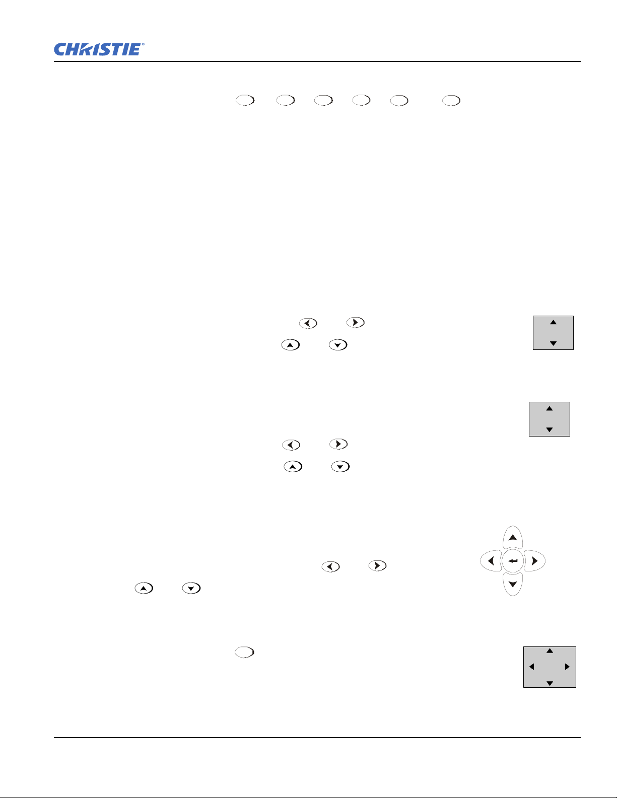
8. Lens Adjustments
Zoom
With the input image displayed:
• If standard IR remote: Press ZOOM + or
• If built-in keypad: Press ZOOM + or
Hold the ZOOM key down to see the effect – arrows in the display indicate the direction of
the zoom. See Figure 2-2.
Focus
With the input image displayed:
• If remote keypad: Press FOCUS + or
• If built-in keypad: Press FOCUS + or
Hold the FOCUS key down to see the effect. Arrows in the display indicate the direction of the focus. See
Figure 2-3 .
Lens Offset
To move the image:
• If standard IR remote: Press either Lens H + or or Lens V
+ or
See Figure 2-4.
Shift
• If built-in keypad: Press + the Arrow keys. See Figure 2-5
Roadster, Matrix WU, Mirage S+/HD/WU User Manual 2-3
020-100002-06 Rev. 1(04-2011)
Page 22

Section 2: Installation and Setup
2.2 Installation Considerations
Although this projector delivers a high-brightness, high-quality output, the final display quality could be
compromised if the projector is not properly installed. This subsection discusses issues you should consider
before proceeding with a final installation. Even if you do not intend to use the projectors in a fixed and
permanent installation, the following information will help you to better understand what you can do to
enhance display performance.
2.2.1 Lifting, Hoisting, and Stacking
For any new installation, you will likely have to safey lift or hoist the projector into place. Keep in mind the
following guidelines for safety.
Lifting
All models include handles for convenient hand transport only
, such as when a projector is lifted from a
shipping container to a table.
Note the following:
• The handles are intended to support the weight of 1 projector only.
• The handles are intended to support a projector for a brief
• The handles are not
extended time periods.
or hoist the projector.
safety points, nor points from which to hoist or suspend the projector.
1) The handles cannot support more than 1 projector. 2) Do not use handles for
3) Do not use the handles as safety points, or as points from which to suspend
time only.
Hoisting
There are 4 integral rigging points on the top of the projector (Figure 2-6) and 8 on the bottom (Figure 2-7)
enable either upright or inverted hoisting. For either orientation, hoist an individual projector, or up to 3
projectors in a stack.
2-4 Roadster, Matrix WU, Mirage S+/HD/WU User Manual
020-100002-06 Rev. 1 (04-2011)
Page 23
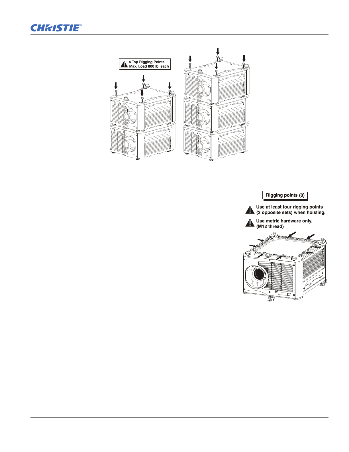
RULES FOR ALL HOISTING
Figure 2-6 Top Rigging Points
Figure 2-7 Bottom Rigging
Points
Section 2: Installation and Setup
• Use at least 4 rigging points for hoisting up to 3 projectors.
• Connect safety cables, and rigging equipment to the designated locations on the projector.
• Use hoisting and rigging equipment suitable to your application such as
clamps, cables, eyebolts, or straps, and which accommodate the load
rating. All integral, metric hardware on the projector accepts an M12
thread only.
• Never hoist a projector by its feet, handles, or any other component
(Figure 2-8).
Roadster, Matrix WU, Mirage S+/HD/WU User Manual 2-5
020-100002-06 Rev. 1(04-2011)
Page 24

Section 2: Installation and Setup
Figure 2-8 NEVER Use Handles for Hoisting or as Safety
Points
Use metric hardware only.
Never force incompatible threads.
Never hoist a projector by its feet,handles, or any other component.
IMPORTANT! Remove the lens before hoisting a projector.
2-6 Roadster, Matrix WU, Mirage S+/HD/WU User Manual
020-100002-06 Rev. 1 (04-2011)
Page 25

2.2.2 Hoisting Procedure
Figure 2-9 Attach Safety Cables
Figure 2-10 Using the Rigging Hardware
This procedure applies to one or more projectors. To hoist a stack, first
stack 2 or 3 projectors according to the stacking procedure included in
this manual. Never stack or hoist more than 3 projectors together.
1. Remove lens.
Remove the projection lens to prevent possible damage during
hoisting. Refer to Section 4.8 Replacing the Projection Lens.
2. Retract feet.
If the projector is inverted, retract the adjustable feet to prevent the
hoisting hardware from getting caught.
3. Attach safety cables.
Attach a safety cable to each of the 2 eyebolts mounted on the
bottom of the projector. See Figure 2-9.
NOTE: Add eyebolts (2) if non-inverted.
Section 2: Installation and Setup
Always use at least 2 safety cables for any
hoisting.
Attach safety cables to the 2 eyebolts.
NOTE: When hoisting a non-inverted projector or stack, add 2 safety eyebolts in the front and rear threaded
holes provided on the top of the projector. Ensure the eyebolts have an adequate rating for the load.
Secure safety cabling to both eyebolts.
4. Attach rigging hardware.
Attach the rigging hardware by securing your rigging
components to the appropriate rigging points. There
are 8 sliding points provided on the bottom. Tighten
the nut at each required location (Figure 2-10) to
prevent sliding.
NOTES: 1) Use at least 4 rigging points for all hoisting.
2) Use straps, clamps or cabling with load
capacity adequate for the total projector weight.
Refer to Section 6 Specifications. 3) Do not join
the rigging straps or cables to a common point,
keep separated as shown.
Roadster, Matrix WU, Mirage S+/HD/WU User Manual 2-7
020-100002-06 Rev. 1(04-2011)
Page 26

Section 2: Installation and Setup
Figure 2-11 Adjust the Feet
• Maximum stack = 3 projectors
• Stack first, then hoist
2.2.3 Stacking Procedure
NOTES: 1) Requires stacking hardware provided standard with Roadsters only. Available separately for
Matrix and Mirage Series. 2) Installation requires at least 2 people.
Roadster, Matrix, and Mirage projectors can be stacked in either the upright or inverted position. Do not
mix orientations (i.e., inverted with upright) in a stack. Secure a maximum of 3 projectors with the stacking
mounts as described below.
Do not stack more than 3 projectors.
Christie stacking hardware required. The top projector could slide off and cause injury
or death.
Never carry a stack.
1. Position the projectors.
• Place each projector to be stacked on a secure
table or cart.
• Place 1 projector on its side to access its adjustable feet, and stacking legs (Figure 2-11).
• Orient the other projector in either upright or
inverted position as required (remember, each
projector in a stack must be in the same orientation).
2. Fully retract the 4 adjustable feet.
Fully retract each foot (4) as far as possible by
turning them clockwise.
• If upright, retract the feet on top projector.
• If inverted, retract the feet on bottom projector
2-8 Roadster, Matrix WU, Mirage S+/HD/WU User Manual
020-100002-06 Rev. 1 (04-2011)
Page 27

3. Extend the 3 stacking legs.
Figure 2-12 Extend 3 Stacking Legs
(UPRIGHT STACK SHOWN)
Figure 2-13 Loosen 2 Nuts
Figure 2-14 Remove Safety Pins
Extend the stacking legs (3) by turning them so that at
least 1 inch of thread is visible on each. This clearance
accommodates the up-or-down movement for aligning
the images from the stacked projectors. Ensure that you
extend all 3 legs equally (see Figure 2-12) so they are
level.
• If upright, extend legs on top projector (shown)
• If inverted, extend legs on bottom projector
IMPORTANT!
Extend the stacking legs equally by at least
1 inch.
4. Loosen the rear stacking leg nuts
On the rear stacking legs (Figure 2-13), loosen
the nuts so the legs have some lateral
movement for easier alignment with the
stacking mounts on the other projector.
Section 2: Installation and Setup
• If upright, release on top projector
• If inverted, release on bottom projector
5. Release and remove three safety pins.
The 3 safety pins must be removed from the stacking mounts so that
the stacking legs can fit into the mounts (Figure 2-14).
• If upright, remove the pins from the mounts on the bottom projector
• If inverted, remove the 3 safety pins from the mounts on the top
projector
6. Place top projector on bottom projector.
With 1 person on each side, lift the top projector on to the bottom
projector, aligning all 3 stacking points between projectors. The legs
(4) should fit inside the stacking mounts.
Minimum of 2 people required.
Roadster, Matrix WU, Mirage S+/HD/WU User Manual 2-9
020-100002-06 Rev. 1(04-2011)
Page 28

Section 2: Installation and Setup
Figure 2-15 Align Holes in Mounts and Legs, and LOCK with Pin
7. Align the holes in the 3 stacking mounts and 3 stacking legs.
On each stacking mount, turn
the adjusting wheel slightly
until the hole in the top portion
of the mount lines up with the
hole in the stacking leg (Figure
2-15).
NOTE: You can increase leverage
by using a screwdriver in the holes.
8. Insert 3 safety pins and LOCK all.
Critical Safety Procedure.
At each of the 3 stacking points, insert the safety pin fully through the holes in the stacking mounts and
stacking legs (Figure 2-15). Ensure that each pin is fully inserted to engage the safety lock and secure the
projectors together. Failure to engage the safety lock could cause the projectors to separate and result in
injury or death.
Failure to engage the safety lock could cause the projectors to separate and result in injury
or death.
9. Leg Nuts.
Before hoisting, firmly tighten the nuts on the 2 rear stacking legs (Figure 2-15). If you are ready to align
the projectors to one another, leave these nuts slightly loose until after the alignment.
10. Repeat steps 1–9 if stacking a third projector.
Never stack more than 3 projectors.
2.2.4 Alignment Procedure
Stacked projectors must be correctly aligned to one another so that the resulting display is optimized and as
sharp as possible. If you are also hoisting the stack, hoist the stack into place first and then align. Lock all
stacking hardware into place to maintain your alignment.
IMPORTANT! Ensure the stacking legs are extended at least 1 inch and are slightly loosened. Refer to
Figure 2-12.
Before You Begin
• Always align to the fixed projector. In floor-mount or table-mount (i.e., non-hoisted) stacks, you will align to
the bottom projector as shown in drawings below. In hoisted stacks, align to the top projector.
• Leg nuts must be loosened before alignment; otherwise the stacking mounts will not turn and allow movement of the projector.
2-10 Roadster, Matrix WU, Mirage S+/HD/WU User Manual
020-100002-06 Rev. 1 (04-2011)
Page 29
Section 2: Installation and Setup
Figure 2-16 Adjustment Directions
(Tilt)
Figure 2-17 Misaligned
Alignment Procedure:
1. Position the first image (fixed projector).
Position the fixed projector’s (first) image as desired and align the other image(s) to it as described below.
2. Display the grid test pattern.
Display the Grid Test Pattern. To distinguish each image, enable “Red” for 1 display and “Green” for the
other. Refer to Section 3.2 Using the Keypads if you need help enabling colors.
3. Adjust Zoom and Focus.
Minimize each projector's zoom and images are in focus.
4. Try aligning the two grid patterns.
Adjust the Zoom and Offset on the top projector to precisely move its test pattern display on to the bottom
test pattern. When properly aligned, all red/green grid lines in the combined image will turn yellow.
• If all lines are well aligned, skip to Step 6. b. to lock all stacking mounts.
• If alignment needs improvement, proceed with the next step.
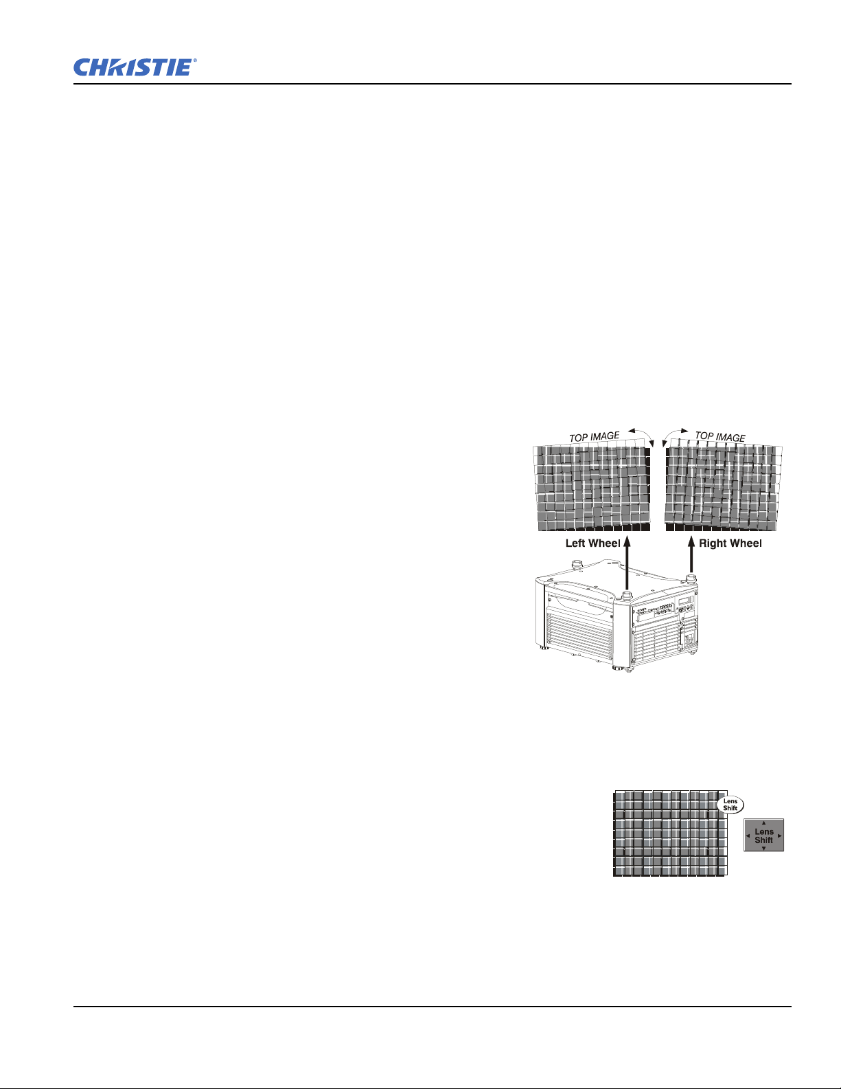
5. Align the centerlines of the grid.
Turn the 2 rear stacking mount wheels to move the top
projector as necessary to achieve well-aligned centerlines.
Use a screwdriver in the holes around the rim of each
adjusting wheel for better leverage and control.
How to move the image. Turn independently; each stacking
mount acts as a pivot point for the opposite edge of the
display (Figure 2-16).
For example:
• Turn the right mount to tilt the left portion of the image up
or down
• Turn the left mount to tilt the right portion of the image up
or down
• Turn the mounts together to raise or lower the top image
like an offset adjustment, or turn the front stacker
If the center lines form an
“X”. This indicates that the
projectors (and images) are slightly tilted in relation to one
another. Turn 1 mount to raise 1 side, and/or turn the other mount to lower the other side. See Figure 2-16.
If the center lines are parallel, but misaligned:
• If centerlines are out by the same amount from top and bottom, use offsets (on top projector) to bring the centerlines into alignment.
Roadster, Matrix WU, Mirage S+/HD/WU User Manual 2-11
020-100002-06 Rev. 1(04-2011)
Page 30

Section 2: Installation and Setup
Figure 2-18 Adjust Front Wheel
Figure 2-19 Secure All Hardware
• If centerlines are parallel, but others are not, turn the
front stacking mount wheel to bring the centerlines
into alignment.
6. Align the edges of the grid with centerlines aligned:
a. Adjust zoom (top projector) to align the edges of its
image with the other image.
b. Adjust focus. When aligned, all lines from the
combined red/green grids will be yellow.
7. Secure all stacking wheels and leg nuts
Critical Safety Procedure.
• Turn all 3 stacking wheels until they are firmly secure against
the rest of the stacking mount. See Figure 2-19.
• Secure both 2 rear leg nuts against the bottom of the projector.
8. Repeat Steps 1 to 7 if stacking a third projector.
2.2.5 Installation Type
Choose the installation type that suits your needs: front or rear screen, floor mount, or inverted mount.
•Easy to set up
• Can be moved or changed quickly
• Easy to access
Front Screen, Inverted Mount (ceiling) Installation
• Does not take up audience space
• Projector is unobtrusive
• Projector cannot be accidentally moved
:
ADVANTAGES CONSIDERATIONS
• Shares floor space with audience
ADVANTAGES CONSIDERATIONS
• Installation is more permanent
• It is more difficult to access the projector
Rear Screen, Floor Mount Installation
• Projector is completely hidden
• Projector is easily accessed
• Usually good ambient light rejection
2-12 Roadster, Matrix WU, Mirage S+/HD/WU User Manual
ADVANTAGES CONSIDERATIONS
• Requires separate room
• Installation cost is usually higher
020-100002-06 Rev. 1 (04-2011)
Page 31
Rear Screen, Inverted Mount (ceiling) Installation
Figure 2-20 Audience Coverage with Flat Screen
• Projector is completely hidden
• Usually good ambient light rejection
Rear Screen, Floor Mount with Mirror
• Projector is completely hidden
• Usually good ambient light rejection
• Requires less space behind screen than
2.2.6 Screen Type
Front Screen Installations
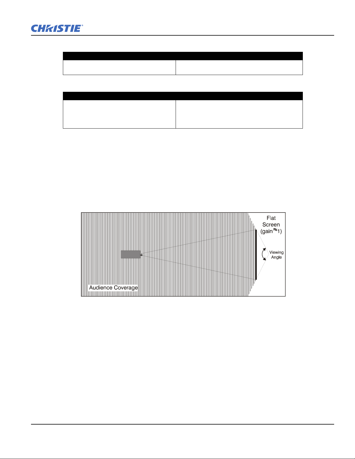
While there are 2 basic screen types, flat and curved, generally flat screens are recommended for this projector
(Figure 2-20). Flat screens offer a gain of about 1 with a viewing angle just less than 180°. Incident light
reflects equally in all directions so the audience can see the display from various angles. Because of the low
gain, flat screens are most effective when ambient lighting is reduced, although this difference may be
negligible given the high brightness output from this projector.
Section 2: Installation and Setup
ADVANTAGES CONSIDERATIONS
• Requires separate room
• Installation cost is usually higher
ADVANTAGES CONSIDERATIONS
• Requires separate room
• Installation cost is usually higher
other rear screen installations
NOTE: Lenses for this projector are designed primarily for use with flat screens, but the projector depth-of-
field range allows the lens to be focused on curved screens as well. While focus remains sharp in the
corners, there may be significant pincushion distortion, primarily at the top of the screen.
Rear Screen Installations
There are 2 basic types of rear screens: diffused and optical. A diffused screen has a surface that spreads the
light striking it. Purely diffused screens have a gain of less than 1. The main advantage of the diffused screen is
its wide viewing angle, similar to that of a flat screen for front screen projection. Optical screens take light
from the projector and redirect it to increase the light intensity at the front of the screen. This increase at the
front reduces the intensity in other areas. A viewing cone, similar to that of a curved front screen installation, is
created.
Roadster, Matrix WU, Mirage S+/HD/WU User Manual 2-13
020-100002-06 Rev. 1(04-2011)
Page 32

Section 2: Installation and Setup
Figure 2-21 Aspect Ratio
To summarize, optical screens are better suited for brightly lit rooms where the audience is situated within the
viewing cone. Diffused screens may be better suited when a wide viewing angle is required but there is low
ambient room lighting.
2.2.7 Screen Size
Choose a screen size, which is appropriate for your lens and application. Keep in mind that if the projector will
be used to display text information, the image size must allow the audience to recognize all text clearly. The
eye usually sees a letter clearly if eye-to-text distance is less than 150 times the height of the letter. Small text
located too far from the eye will likely be illegible at a distance no matter how sharply, and clearly it is
displayed.
To fill a screen with an image, the aspect ratio of the screen should be equal to the aspect ratio of the image
(expressed as the ratio of its width to its height). Standard video from a VCR has a 4:3 or 1.33:1 aspect ratio.
For example, to display a VCR output with a 4:3 aspect ratio onto a 10-foot (3m) high screen, the width of the
screen must be at least 13.3 feet (4m).
Ideally, to fill a screen with an image, the aspect ratio of the screen should be equal to the aspect ratio of the
image. The aspect ratio of an image is expressed as the ratio of its width to its height such as a 4:3 aspect.
Standard video from a VCR has a 4:3 aspect ratio. For example, to display a VCR output with a 4:3 aspect ratio
onto a 10-foot (3m) high screen, the width of the screen must be at least 13.3 feet (4m).
2.2.8 Screen Aspect Ratio
Aspect ratio describes the proportion of the screen and is expressed as the ratio
of width to height, such as “4:3” or “5:4”. . Although image size and image
aspect ratio can both be adjusted quickly through projector software, it is still a
good idea to choose a screen aspect ratio that is most appropriate for your
intended applications.
Ideally, to exactly fill a screen with an image, the aspect ratio of the screen
should correspond to the aspect ratio of the image, which depends on the source
in use. For example, standard video from a VCR has a 4:3 ratio
(approximately), whereas a high-resolution graphics signal typically has a 5:4
aspect ratio. By default, images from your projector will be as large as possible and will maintain their aspect
ratio.
The SXGA+ (1400 x 1050) aspect ratio for the Roadster S+ and Mirage S+ models are 4:3 (Figure 2-21) and
the HD (1920 x 1080) aspect ratio for the Roadster HD and Mirage HD models is 16:9.
2.2.9 Ambient Lighting
The high brightness of this projector is well suited for locations where ambient lighting might be considered
less than ideal for projection. A typical room with ceiling lights and windows rarely requires special attention.
Contrast ratio in your images will be noticeably reduced only if light directly strikes the screen, such as when a
shaft of light from a window or floodlight falls on the image. Images may then appear washed out and less
vibrant.
In general, avoid or eliminate light sources directed at the screen.
2-14 Roadster, Matrix WU, Mirage S+/HD/WU User Manual
020-100002-06 Rev. 1 (04-2011)
Page 33

2.2.10 Other Considerations
Other considerations and tips that can help improve your installation:
• Keep the ambient temperature constant and below 35°C (95°F). Keep the projector away from heating and/
or air conditioning vents. Changes in temperature may cause drifts in the projector circuitry that may affect
performance.
• Keep the projector away from devices that radiate electromagnetic energy such as motors and transformers.
Common sources of these include slide projectors, speakers, power amplifiers, elevators, etc.
• Choose the best screen size for the application. Since more magnification reduces brightness, use a screen
size appropriate for the venue but not larger than required. Installing a large screen in a small room is similar
to watching television at a close range; too large a screen can overpower a room and interfere with the overall effect. A good rule of thumb is to be no closer than 1.5 times the width of the screen.
2.3 Projector Position and Mounting
2.3.1 Throw Distance
You can quickly estimate the throw distance by taking the horizontal width of the screen and multiplying it by
the lens throw ratio. The result of this calculation tells you roughly how far back the projector should be
positioned from the screen in order to project a focused image large enough to fill the screen.
For example:
Section 2: Installation and Setup
• Screen Width = 10 feet
• Lens Type is 0.7:1
• Throw Distance (TD) = 10 feet x 0.7 = 7 feet
IMPORTANT! Use the lens and screen size to calculate the precise throw distance using the
tables provided in the Dealer Section of the Christie Website, PN 020-100298-xx. Due to lens
Roadster, Matrix WU, Mirage S+/HD/WU User Manual 2-15
020-100002-06 Rev. 1(04-2011)
Page 34

Section 2: Installation and Setup
Figure 2-22 Calculating Throw Distance
Figure 2-23 Maximum Vertical Offset
manufacturing tolerances for lens focal length, actual throw distance and vary ±5% between
lenses with the same nominal throw ratio.
2.3.2 Vertical & Horizontal
The Vert ic al position of the projector in
relation to the screen also depends on the
size of the screen and the lens type. Correct
vertical position helps ensure that the image
will be rectangular in shape rather than
keystoned (having non-parallel sides), and
that image focus and brightness both remain
optimized.
If necessary, vertical position of the image
can be offset (i.e., moved up or down in
relation to lens center) by using the
motorized Offset function.
Starting with no offset, the image from this
projector can be moved up or down by a
maximum distance of 525 pixels for
SXGA+ resolution and 643 pixels for HD
and WUXGA resolution, resulting in the
entire image (more for HD/WUXGA) being
displayed above or below lens center. See
Table 2.1 and Figure 2-23.
NOTE: Not applicable for a fixed lens.
2-16 Roadster, Matrix WU, Mirage S+/HD/WU User Manual
020-100002-06 Rev. 1 (04-2011)
Page 35

The Horizontal position of the image can be offset (i.e., shifted left or
Figure 2-24 Maximum Horizontal
Offset
right of lens center) by using the motorized offset function. Starting
with no offset, the image from this projector can be moved left or right
by a maximum distance of 350 pixels for SXGA+ resolution and 403
pixels for HD and WUXGA resolution, resulting in approximately
75% of the image displayed to 1 side of lens center. See Ta ble 2 .1 and
Figure 2-24.
NOTES: 1) If the image becomes keystoned or exhibits uneven
brightness, the projector may simply be too high or low in
relation to the screen. 2) Recommended offset ranges can be
exceeded, however this may affect image quality. 3)
Simultaneous horizontal and vertical offset limits the
adjustment range of each. 4) Offset can vary by ±7% and may
be affected by the degree of zoom currently in use.
Section 2: Installation and Setup
Table 2.1 Lens Offsets
Lens Type Offset Movement Max. Amount of Display
(All motorized
lenses)
SXGA+ Lenses 100% 50% 1050 pixels or 100% 1050 pixels or 75%
HD Lenses 119% 42% 1183 pixels or 100% 1363 pixels or 71%
WU Lenses 112% 54% 1243 pixels or 100% 1478 pixels or 77%
or or
NOTES: 1) Offsets are subject to ±7% centering tolerance 2) % Offset = # pixels of offset / half panel
resolution x 100. 3) 0.73:Fixed and 1.16-1.49 Zoom Lenses have less offset. Refer to Specification
section, Lenses for more details.
2.3.3 Tilting the Projector
The projector can be rotated and mounted at any vertical angle (i.e., you can tilt the face of the projector up or
down as much as desired for your installation). Side-to-side tilt, however, must not exceed 15° (Figure 2-25).
Keeping the projector fairly level in this manner ensures that the lamp axis is level, and is required for safe and
reliable lamp operation. Always vent exhaust air away from the lens.
Above or Below Lens Center
Max. Amount of Display
Right or Left of Lens Center
Roadster, Matrix WU, Mirage S+/HD/WU User Manual 2-17
020-100002-06 Rev. 1(04-2011)
Page 36
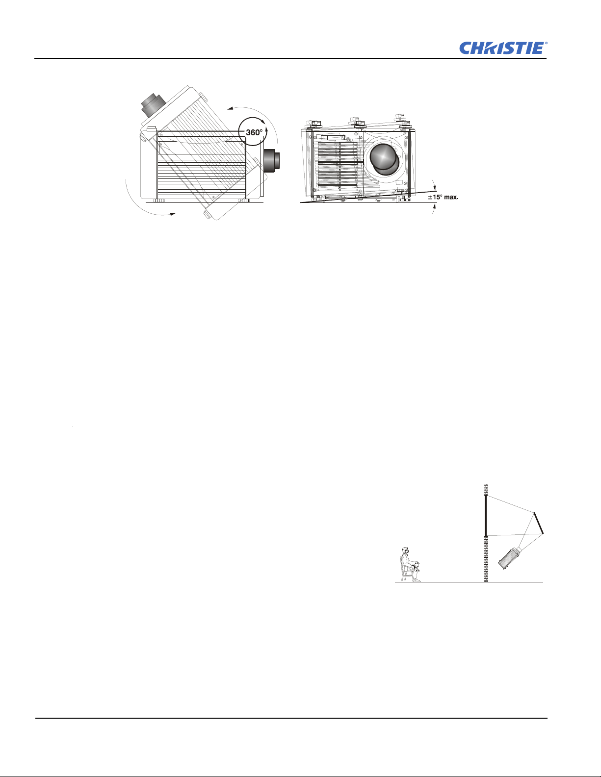
Section 2: Installation and Setup
Figure 2-25 Vertical and Horizontal Tilt Ranges
Figure 2-26 Rear Screen Projec-
tion
2.3.4 Mounting
There are several methods for mounting the projector. Depending on your chosen installation, one method may
be more suitable than another. In typical front and rear screen installations the projector can be mounted to a
secure and level surface, such as a table or cart. Carts are useful when the projector has to be moved during a
presentation or from site to site. It is recommended you lock the wheels on a cart, when it’s in position, to
prevent someone from accidentally moving it during a presentation.
Ceiling Mount
The projector can also be inverted and suspended from the ceiling using a specially designed ceiling mount
fixture. This type of mounting is recommended for fixed installations and for those that want the projector out
of plain view or have a limited amount of space for projector and audience. For more information, contact your
dealer.
Use only the Christie-approved ceiling mount kit designed for your projector. Refer to
the installation instructions and safety guidelines provided in the ceiling mount kit. For more
information, contact your dealer.
2.3.5 Folded Optics
In rear screen applications (Figure 2-26) where space behind the
projector is limited, a mirror may be used to fold the optical path. The
position of the projector and mirror must be accurately set. Consult your
dealer or Christie for details.
2.4 Connecting Sources
Sources connect to the Input Panel located on the rear of the projector.
As shown in Figure 2-27.
The upper right corner (
can also be used for YPbPr signals or additional video sources. Just beside these BNCs, the DVI-I connector
(
INPUT 2) accepts digital or analog display signals from a computer. Connect analog composite video at INPUT
or S-video at INPUT 4 from devices such as VCRs, laser disc players or DVD players.
3
INPUT 1) typically accepts an RGB signal from an external analog RGB source, or it
2-18 Roadster, Matrix WU, Mirage S+/HD/WU User Manual
020-100002-06 Rev. 1 (04-2011)
Page 37

Section 2: Installation and Setup
Note:
Dual SD/HD-SDI Option Module shown.
Standard in Roadster S+16K/+12K, HD12K,
HD18K, S+20K projectors.
Figure 2-27 Input Panel
There are also several optional interfaces available for connecting other sources—these interfaces slide into the
remaining unused option slot, and can be done while the projector is running.
NOTES: 1) Refer to Section 6 Specifications for details regarding compatible inputs. 2) Only use high quality
shielded cables for all connections. 3) The Dual SD/HD-SDI module shown is standard on the
Roadster models, optional for the Matrix and Mirage series.
2.4.1 RGB Signals
INPUT 1 consists of 5 BNCs (connectors) for linking to a variety of RGB sources such a PC, Mac, DEC, Sun,
SGI, and others. This projector supports multiple Sync types with RGB signals: sync-on-green, composite
sync, and separate H & V syncs.
NOTE: Depending on your source, you may need a custom adapter cable with BNC connectors at the
projector end and a different type of connector at the other (such as a 15-pin “D” connector for some
computer sources). Contact your dealer for details.
Connect the
and
BLUE BNCs on the INPUT 1 panel. If the source uses sync-on-green, only the red, green, and blue
connections are required.
If the source provides a composite sync output, connect it to the
provides separate horizontal and vertical sync outputs, connect horizontal sync to the
COMP, and connect vertical sync to SYNC input labeled VERT. See Figure 2-28, below.
SYNC BNC input(s) first. Then connect the red, green, and blue source outputs to the RED, GREEN,
SYNC input labeled HOR/COMP. If the source
SYNC input labeled HOR/
Roadster, Matrix WU, Mirage S+/HD/WU User Manual 2-19
020-100002-06 Rev. 1(04-2011)
Page 38

Section 2: Installation and Setup
Figure 2-28 Connecting RGB Input
Figure 2-29 Connecting YPbPr
NOTES: 1) If for some reason the projector fails to recognize a signal as an RGB signal, specify this Color Space
option within the Image Settings menu. Refer to Section 3.5 Adjusting the Image. 2) To connect YPbPr
signals (such as from DVDs or analog HDTV sources) to
described in Section 2.4.2 YPbPr (Component Video) (below).
2.4.2 YPbPr (Component Video)
INPUT 1, use the red, green and blue BNCs as
Connect a YPbPr signal (a.k.a. component video) to INPUT 1 or INPUT 2 as shown in Figure 2-29 .
NOTES: 1) If, for some reason, the projector fails to recognize a YPbPr signal, specify this Color Space option
within the Image Settings menu. Refer to Section 3.5 Adjusting the Image. 2) Do not connect digital
component signals (known as YCbCr) to
installed at
INPUT 5 or 6.
INPUT 1 or 2. Use the appropriate digital interface option
2.4.3 Composite Video
INPUT 3 and INPUT 4 provide simultaneous connection of both a composite video source (INPUT 3) and an
S-Video source (INPUT 4). Refer to Figure 2-30.
2-20 Roadster, Matrix WU, Mirage S+/HD/WU User Manual
020-100002-06 Rev. 1 (04-2011)
Page 39

2.4.4 DVI Digital Video
Figure 2-30 Connecting Composite Video
Use the DVI-I connector at INPUT 2 to connect either analog or digital video devices to the projector. When
connecting devices that transmit an analog video signal such as VCRs, laptops, and PCs use the DVI cable
provided with the projector. Plug the DVI-I (single link) connector end to the projector and the 15-pin VGA
connector to the device.
Section 2: Installation and Setup
Use a cable with DVI-I connectors at both ends to connect devices that transmit digital and analog video
signals such as high-quality DVD players, satellite receiver and digital cable TVs.
NOTES: 1) To ensure true digital output from devices that transmit digital signals, connect to the DVI-I
connector. 2) DVI loop through is not available unless you have the optional DVI Input Module
installed at INPUT 5 or INPUT 6.
2.4.5 Dual SD/HD-SDI
Christie’s Dual SD/HD-SDI input module is standard with Roadster models and factory-installed in INPUT 5
or INPUT 6. The module’s loop-through capability enables incoming serial digital data to be tiled across
multiple screens, creating vast “mega resolution” displays. Alternatively, the multiple outputs can be
overlapped for extra-bright displays, or simply distributed to additional projectors for multiple screens of the
same image.
The module accepts 1 or 2 independent standard- or high-definition serial digital inputs, decodes them for
processing in the main electronics of the projector, and outputs 10-bit YCbCr 4:2:2 video. Either input can be
set as the active primary or secondary part of a Picture-in-Picture (PIP) display, and either input can be looped
through to 1 (or both) of the module’s BNC outputs.
NOTE: Selection of these inputs is described in Section 3.2 Using the Keypads.
Connect a compatible SMPTE 292M or SMPTE 259M-C source(s) to 1 or both of the inputs located on the left
side of the module. The module will automatically detect the standard at each input and configure itself
accordingly for correct termination of the signal. The module also detects and supports dual link 292M and
SMPTE 372M video standards. For full details, consult the Dual SD/HD-SDI manual.
Roadster, Matrix WU, Mirage S+/HD/WU User Manual 2-21
020-100002-06 Rev. 1(04-2011)
Page 40

Section 2: Installation and Setup
2.4.6 Other Optional Inputs
Optional modules allow you to increase your total number of inputs and/or accommodate different signal
types, whether analog or digital. Install in the areas labeled INPUT 6 or (if available)
Options include:
• RGB 500 Input Module
• RGB 400BA Input Module
• RGB 400 Active Loop Thru Input Module
• Composite/S-Video Input Module (
• PC250 Analog Input Module
• Serial Digital Input Module
• DVI Input Module (optional on Mirage HD18)
• Dual SD/HD-SDI Module
For even more sources, connect a third-party switcher to the RS-232 IN port, or, if RS-422-compatible, connect
to the RS-422 port.
NOTES: 1) Optional digital interfaces cannot be used in a Marquee Case/Power Supply. 2) Refer to Appendix
D: Optional Input Modules for a brief description of each interface.
INPUT 5.
not currently supported with software v1.1 or higher)
(optional on Matrix and Mirage models))
2.5 Connecting Communications
As an alternative to the projector’s keypad or remote, you may wish to communicate with the projector using a
PC or other controller. Such a device sends commands and receives feedback via serial links (RS-232 and RS-
422), Ethernet or GPIO communications to the projector, all described below.
2.5.1 Remote Keypads
As desired, direct the projector's IR remote keypad towards the display screen or the projector's IR sensors.
Alternatively, connect a wired (tethered) version of the remote to the 3.5mm RCA jack labeled as REMOTE
on the projector's Input panel.
NOTE: The response to a wired keypad must also be enabled in the Communications menu. Refer to Section
3.6 Adjusting System Parameters and Advanced Controls for more information.
2.5.2 Serial Port Connections
There are 2 types of serial ports available on the projector: RS-232 and RS-422. You can connect a device with
a serial interface, such as a computer to either of these connectors (not both) and control the projector remotely
by entering specific serial communication commands.
Connecting RS-232
The two 9-pin DIN connectors labeled RS-232 IN and RS-232 OUT on the input panel are dedicated to serial
communication (refer to Figure 2-31). Using the appropriate serial communication cables (refer to Appendix
B: Serial Communication Cables) connect the controlling source, such as a personal computer to the RS-232
IN connector. Then set the baud rate to match that of the computer. Refer to Section 3 Operation for details on
changing the projector’s baud rate.
2-22 Roadster, Matrix WU, Mirage S+/HD/WU User Manual
020-100002-06 Rev. 1 (04-2011)
Page 41
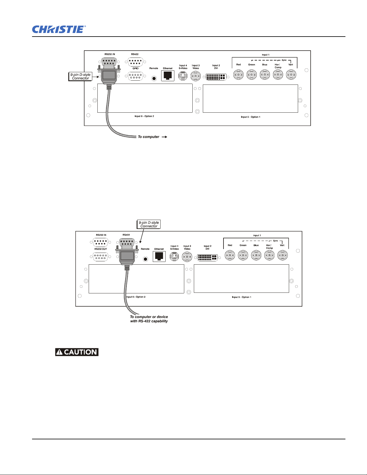
Section 2: Installation and Setup
Figure 2-31 RS-232 Serial Communications
Figure 2-32 RS-422 Connection to a Computer
Connecting RS-422
If you wish to control the projector with a computer and or other controlling device with RS-422 capability,
connect a RS-422 serial communication cable between the computer and the RS-422 port on the projector. See
Figure 2-32. RS-422 is better suited for serial communication over long distances then is RS-232 communica-
tion.
Do not use an RS-422 port unless you are using equipment with RS-422 capability. The
voltage levels of this signal can damage incompatible equipment.
2.5.3 Ethernet Communications
To add the projector to an existing Ethernet network with other equipment such as controllers and other
projectors, connect standard CAT5 Ethernet cable between your Ethernet controller (or hub) and the Ethernet
port at the rear of the projector as shown in Figure 2-33.
CONNECTING TO A PC: If you are connecting the Ethernet port directly to a PC (rather than a network or
hub), ensure a crossover Ethernet cable is used.
Roadster, Matrix WU, Mirage S+/HD/WU User Manual 2-23
020-100002-06 Rev. 1(04-2011)
Page 42
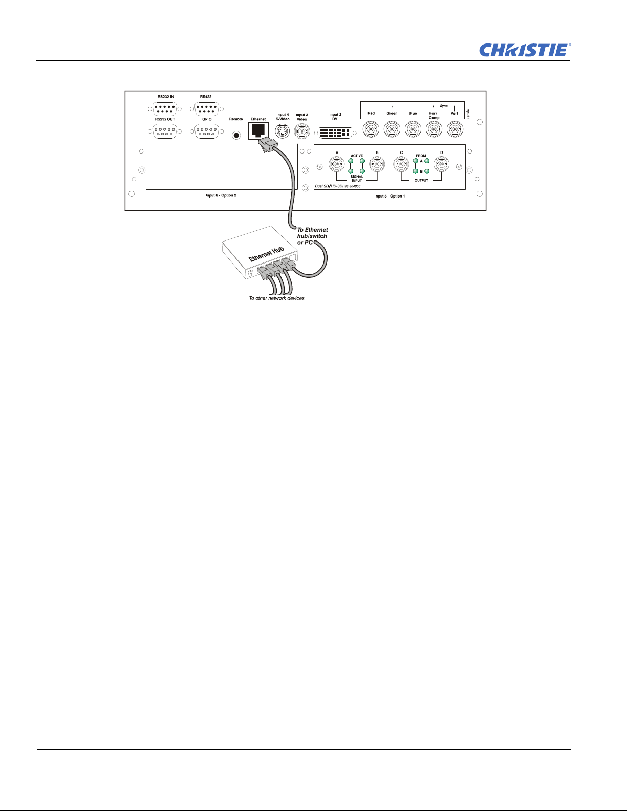
Section 2: Installation and Setup
Figure 2-33 Connecting Ethernet
Upon connection to an Ethernet network, the projector’s factory default IP address of 0.0.0.0 will
automatically enable the DHCP function (if available on the network) to assign a new IP address that is valid
and unique for that network. Or, if there is no DHCP function available on the network (or if a specific static IP
address for the projector is preferred or required), you can set the address in the Ethernet Settings secondary
menusecondary menu or via an ASCII serial command.
NOTE: Ensure the projector is connected to the network before attempting to change its IP address.
Regardless of how it is assigned, once a projector has a valid and unique address, it will respond to commands
sent to this address. To determine the projector’s current IP address, consult the
Status or Communications
menus.
Refer to Section 3.6 Adjusting System Parameters and Advanced Controls for further information about setting
up and using a projector connected via Ethernet.
The GPIO Port
The General Purpose In-Out (GPIO) port enables integration of the projector within an established control
system (Figure 2-34). ASCII commands sent via the GPIO link are stored in projector memory, where they can
be triggered as a sequence of events in the future. Refer to Appendix D: Optional Input Modules.
2-24 Roadster, Matrix WU, Mirage S+/HD/WU User Manual
020-100002-06 Rev. 1 (04-2011)
Page 43
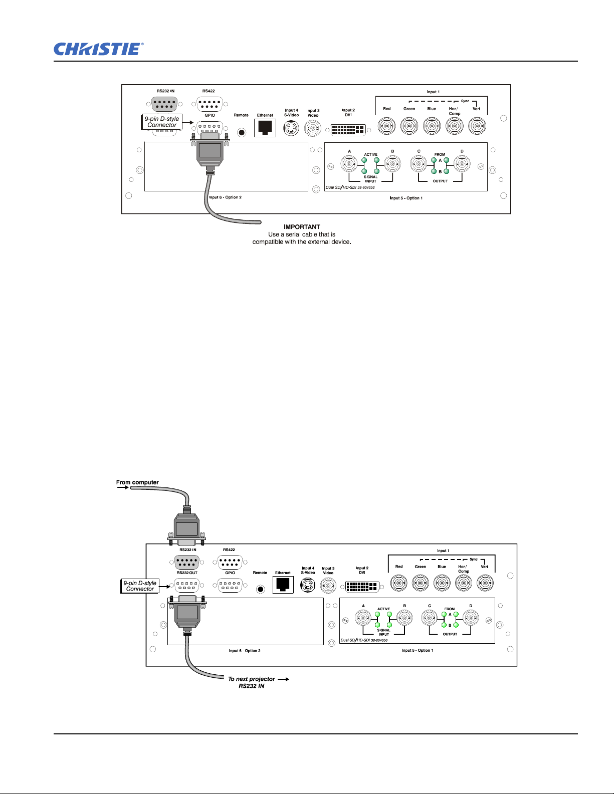
2.6 Connecting Multiple Projectors
Figure 2-34 GPIO Port
Figure 2-35 RS-232 Serial Link Loop-Through at First Projector
You may wish to chain 2 or more projectors together so that commands and communications to and from a
controller are relayed to all projectors. Choose a hardware configuration that best suits your desired
communication method.
Section 2: Installation and Setup
2.6.1 Serial Links
To control multiple projectors with a computer/controller having an RS-232 interface, first set all projectors to
the same baud rate as the controller, then chain the projectors together by connecting the
of the first projector (already connected to the computer/controller) to the
projector in the chain. Continue connecting projectors in this manner until you’ve reached the last projector in
the chain, so that only the last projector has an unused
RS-232 OUT connector
RS-232 IN connector of the next
RS-232 OUT port. See Figure 2-35 .
Roadster, Matrix WU, Mirage S+/HD/WU User Manual 2-25
020-100002-06 Rev. 1(04-2011)
Page 44
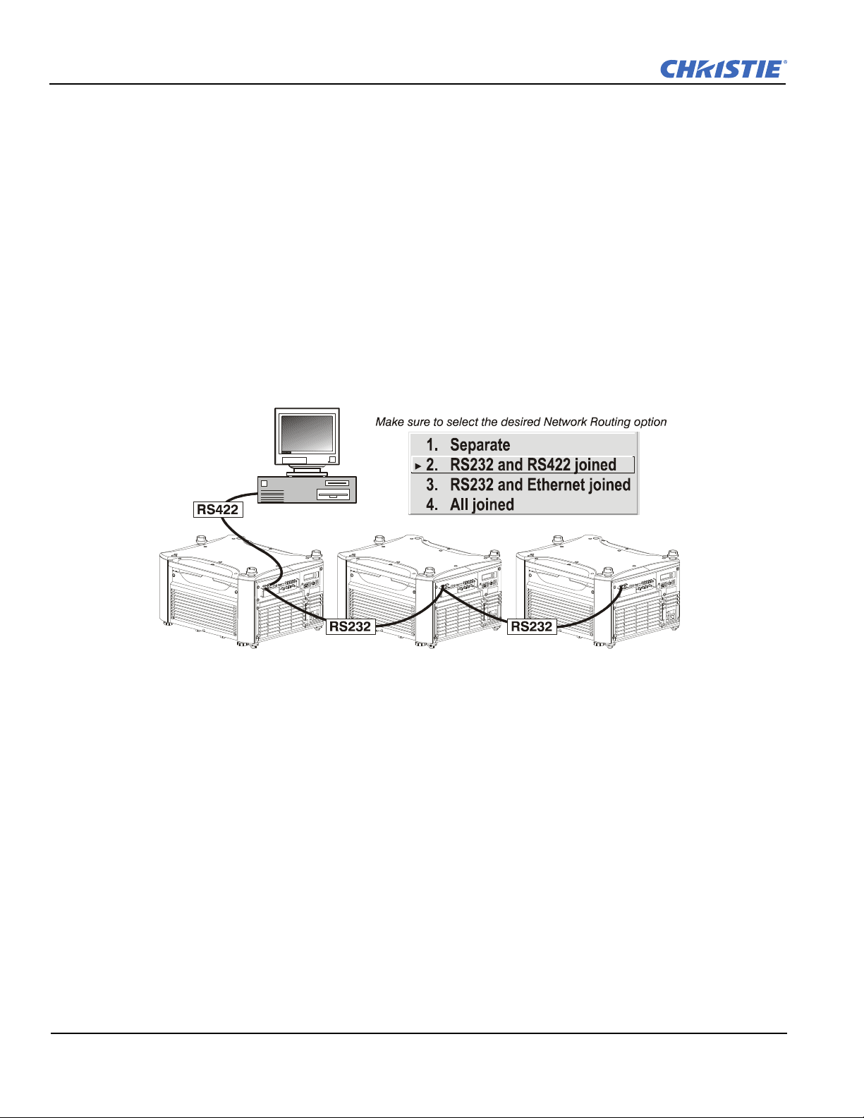
Section 2: Installation and Setup
Figure 2-36 Mixed Serial Network
MIXED NETWORK: To control multiple projectors with a computer/controller having an RS-422 interface, first
set them all to the same baud rate as your RS-422 controller.
NOTE: You must enable this combination of RS-422 and RS-232 in the Communications menu. Set the
“Network Routing” option to “RS-232 and RS-422 Joined”. Refer to Section 3 Operation for details.
Chain the projectors together by connecting an
computer/controller through the
RS-422 port) to an RS-232 port on the next projector in the chain. Continue
RS-232 port of the first projector (already connected to the
connecting projectors in this manner until you’ve reached the last projector in the chain, so that only the last
projector has 1 unused
RS-232 port. See Figure 2-36.
Communication parameters such as baud rate must be set to match the particular controlling device before
connecting as a network. Refer to the documentation that came with your controlling device in order to
determine the proper baud rate. If you need help changing the projector’s baud rate, refer to Section 3.6
Adjusting System Parameters and Advanced Controls. In addition, set the Network Routing to “RS-232 and
RS-422 Joined” if you want to reach all projectors.
NOTES: 1) To avoid damage, connect only properly wired serial communication cables. Refer to Appendix B:
Serial Communication Cables for details. 2) It is recommended that each RS-232 communication
cable be no more than 25 feet in length. Use high quality cables.
2.6.2 Ethernet Networks
To add 1 or more projectors to an Ethernet network, use standard CAT5 cable to connect each projector’s
Ethernet port to a hub on to the network. A controller or PC must also be connected to the hub. Refer to Figure
2-37.
2-26 Roadster, Matrix WU, Mirage S+/HD/WU User Manual
020-100002-06 Rev. 1 (04-2011)
Page 45
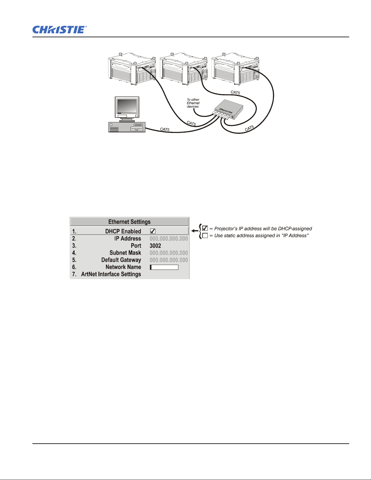
Section 2: Installation and Setup
Figure 2-37 ypical Ethernet Network
Figure 2-38 Setting the Projector’s IP Address
SETTING THE PROJECTOR’S IP ADDRESS: Upon connection to most Ethernet networks, each projector’s
factory default IP address of 0.0.0.0 triggers the network’s DHCP (Dynamic Host Configuration Protocol)
server function to automatically assign an IP address that is valid and unique for use on that network.
Depending on the network, this DHCP-assigned IP address usually remains stable for a single session, but may
change with subsequent power-ups and logins. On some networks, the address will remain stable from session
to session. In all cases, the projector’s IP address and port appear in the
Status menu as well as the Ethernet
Settings secondary menu. See Figure 2-38.
If a projector’s IP address is anything other than 0.0.0.0 (shown as 000.000.000.000 in the Ethernet Settings
menu) upon connection to an Ethernet network, or if DHCP is not available on the network, the automatic
DHCP server function for supplying a valid and unique IP address to the projector is disabled. Instead, a
specific and static IP address must be defined in projector memory. Enter the new address in the Ethernet
Settings submenu, or send to the projector via a serial command. The IP address will be in effect until it is
changed again, or until the DHCP check box is re-enabled for use with a DHCP server on the network.
NOTE: Only the port and IP address of the projector can be changed. The subnet mask is fixed
(255.255.255.0).
CHANGING THE PORT#: On some Ethernet networks, firewall restrictions may require that the port number of
the projector be changed from its default of 3002. If so, enter a new port number in the
Ethernet Settings
menu or include the new port# in an XIP serial command sent to the projector. It is highly recommended not to
use a port# below 1024, as these ports are typically reserved for and used by well known applications.
SUBNET MASK AND DEFAULT GATEWAY: The Subnet Mask and Default Gateway are automatically assigned
when DHCP is enabled. If a static IP is being used, it must be assigned before the subnet mask. The Default
Gateway is an optional router device used to send and receive data outside the subnet.
Roadster, Matrix WU, Mirage S+/HD/WU User Manual 2-27
020-100002-06 Rev. 1(04-2011)
Page 46

Section 2: Installation and Setup
Figure 2-39 Keeping Communications Separate (default)
Figure 2-40 Joining All Networks
ArtNet INTERFACE SETTINGS: Refer to Section 3.6.2 System Configuration (Communication) for additional
information about ArtNet settings.
2.6.3 Separating Networks
By default, communications originating from 1 type of serial controller (RS-232 vs. RS-422 vs. Ethernet) stays
on the corresponding network path. A “Separate” setting indicates this separation for “Network Routing” in the
Communications menu. If you are using an RS-422 controller, for example, it will communicate only with the
projector to which it is connected unless you change this setting to either “RS-232 and RS-422 Joined” or “All
Joined”. See Figure 2-39.
2.6.4 Communicating to All Ports
To relay all messages to all ports (RS-232, RS-422, and Ethernet) set the “Network Routing” option in the
Communications menu for each projector to “All Joined”. This configuration is useful if you are using a nonRS-232 controller with the RS-232 linking available between these projectors. For example, you may want to
use both an RS-422-compatible controller, and an Ethernet-connected PC for working with a network of
projectors linked via their RS-232 in/out ports. Refer to Figure 2-40.
To isolate just RS-422 communications, select “RS-232 and Ethernet Joined”. In Figure 2-40, only projector
#3 will respond to the RS-422 controller. To isolate just Ethernet communications, select “RS-232 and RS-422
Joined”. Only projector #1 will respond via Ethernet.
2-28 Roadster, Matrix WU, Mirage S+/HD/WU User Manual
020-100002-06 Rev. 1 (04-2011)
Page 47

2.7 Power Connection
Figure 2-41 Image Orientation
The North American rated line cord is provided with each projector. Ensure that you are
using a line cord that meets the appropriate rating standards.
Plug the projector’s high-current line cord into the line input socket located in the lower right corner of the rear
panel of the projector, then plug the 3-pronged end of the line cord into a grounded AC outlet. Ensure the
socket outlet is installed near the equipment and is easily accessible. Input voltage to all Roadster and Mirage
models must be capable of 200 –240 VA C . Use the proper power source and the high-current rated line cord
provided. Refer to Section 6 Specifications for all power requirements.
Do not attempt operation if the AC supply and cord are not within the specified
voltage and power range.
Caution for Shutdowns: Once the projector is turned OFF ( ), the lamp cooling fans
will continue to run for approximately 5 minutes to ensure that the projector and lamp have sufficiently cooled,
at which point the fans will automatically shut OFF. To avoid thermal stress that can lead to premature lamp
failure, never unplug the line cord while the lamp cooling fans are running, and never unplug to power down.
2.8 Operating Orientation
Section 2: Installation and Setup
In the Configuration Menu highlight and select
the “Image Orientation” drop-down list. See
Figure 2-41. Select from options Rear, Inverted
Rear, Front, or Inverted Front according to your
intended installation. Refer to Section 3 Operation
for further information.
2.9 Leveling
For most installations, the lens surface of the
projector is parallel to the screen. This prevents
major keystoning of the image (i.e., an image with non-parallel sides). In addition, the projector must be kept
level from side-to-side in order for the lamp to function safely. To make small corrections to the projector’s
level, rotate each leg as necessary to raise or lower. Refer to Figure 2-42.
Roadster, Matrix WU, Mirage S+/HD/WU User Manual 2-29
020-100002-06 Rev. 1(04-2011)
Page 48

Section 2: Installation and Setup
Figure 2-42 Adjusting the Feet Height
Zoom
Figure 2-43
Focus
Figure 2-44
For angled installations, refer to “Special Mounting” under Section 2.3 Projector Position and Mounting
discussed earlier in this section.
2.10 Zoom, Focus and Lens Offset
Once the projector is properly set up and producing an image, you are ready to make quick lens adjustments.
Refer to Section 3.2 Using the Keypads and Section 3.3 Navigating the Menus if you are unfamiliar with using
the keypad and Menu system.
2.10.1 Lens Adjustments
NOTE: Not applicable to fixed lenses. Focus fixed lens by turning focus ring on lens.
Zoom
With the input image displayed:
• If standard IR remote: Press ZOOM + or
• If built-in keypad: Press ZOOM + or
Hold the ZOOM key down to see the effect – arrows in the display indicate the direction of
the zoom. See Figure 2-43.
Focus
With the input image displayed:
• If remote keypad: Press FOCUS + or
• If built-in keypad: Press FOCUS + or
Hold the FOCUS key down to see the effect. Arrows in the display indicate the direction of the focus. See
Figure 2-44 .
2-30 Roadster, Matrix WU, Mirage S+/HD/WU User Manual
020-100002-06 Rev. 1 (04-2011)
Page 49
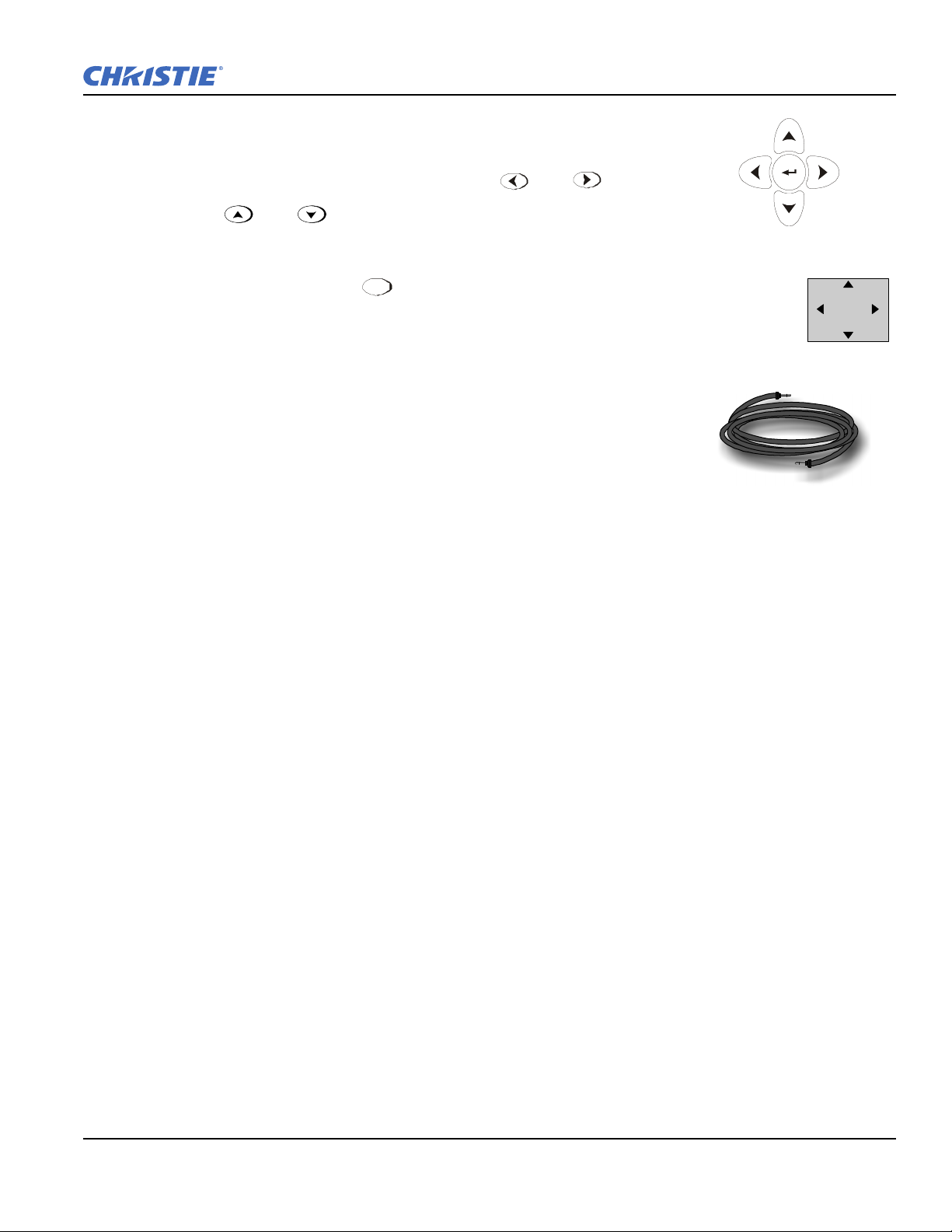
Lens Offset
Figure 2-45 Arrow Keypad
Lens
Shift
Figure 2-46
Lens
Figure 2-47 Sample Wired
Remote Cable
To move the image:
• If standard IR remote: Press either Lens H + or or Lens
Section 2: Installation and Setup
V + or
See Figure 2-46.
Shift
• If built-in keypad: Press + the Arrow keys. See Figure 2-5
2.11 Keypad and Remote Protocols and Conversion
Both styles of remote IR keypads (ergonomic or “Brick” rental staging
Standard IR remote) can be converted to a wired remote by adding the
appropriate cable (provided, as shown in Figure 2-47). This is most useful for
simple applications in which it is impractical to communicate via IR, such as
when the projector is in another room and cannot respond to an IR signal (too
dark), or when you wish to connect to and control individual projectors within
a group.
To control the projector when signals from a remote cannot reach the projector, use the projector’s rear built-in
keypad. The nearby LED display provides feedback indicating current status and activities of the projector.
Because the built-in keypad has fewer keys than the remote’s keypad, certain projector functions are accessible
only through the Menu system rather than via a direct key press.
NOTE: The built-in keypad cannot be disabled.
In addition, the rental staging keypad typically used with Roadsters can operate under a variety of different IR
protocols, useful in multiple-projector sites where you prefer the tether-less freedom of controlling many
adjacent projectors independently. When keypad A operates under a different protocol than keypad B (or
others), each keypad communicates with the projector(s) having a matching protocol defined in memory only.
See below.
Roadster, Matrix WU, Mirage S+/HD/WU User Manual 2-31
020-100002-06 Rev. 1(04-2011)
Page 50

Section 2: Installation and Setup
2.11.1 Ergonomic Keypad
This style of keypad offers one protocol (A) only, and can be converted for wired use as
follows:
1. Using the built-in keypad, display the
Keypad option.
2. Connect the IR remote keypad to the phono jack Input labeled
projector’s Input panel.
2.11.2 Standard IR Remote
NOTES: 1) Typically used for Roadsters. 2) Protocols B-G described here require main
projector software v1.2d or higher.
At manufacture, the remote keypad is assigned “A” as its default protocol, which is simply
a collection of settings that determines how the IR keypad operates. Once assigned, a
protocol remains in effect until it is changed. That is, the remote keypad will operate as it
currently does until you change its protocol. Each rental staging remote can operate using 1
of 7 different IR protocols, or it can be set to a “wired” protocol for use when a cable
connects the remote to the projector. Change protocol via “hard-wired” jumper settings
inside the keypad, set projector software to match, and add or remove the keypad cable as
necessary.
Communications menu, and choose the Wired
REMOTE on the
NOTE: Match the protocol on the projector to that of a remote by accessing the
Communications secondary menu. Refer to Section 3.6 Adjusting System
Parameters and Advanced Controls for further information on how to define which
protocol the projector's infrared sensors (rear and front) will recognize.
2.11.3 Setting the Protocol
To convert the Roadster “Brick” rental staging – Standard IR remote from IR to wired use (or vice versa), set
its protocol accordingly. See below.
2-32 Roadster, Matrix WU, Mirage S+/HD/WU User Manual
020-100002-06 Rev. 1 (04-2011)
Page 51

Section 2: Installation and Setup
Figure 2-48 Opening the “Brick” rental staging – Standard IR remote
Figure 2-49 Setting the Jumpers in the “Brick” rental staging – Standard IR remote
1. Unlatch and open the battery compartment on the back of the keypad as shown in Figure 2-48.
2. Find the 4 jumpers located along the latching side of the battery compartment. These jumper settings
establish the protocol to be used so that the remote functions in a certain manner.
3. Set the jumpers to match 1 of the protocols shown in Figure 2-49. Use tweezers or needle-nose pliers to
remove and replace each jumper as necessary.
• J1 jumper: Set between 1 and 2 or 2 and 3 as required for the desired protocol.
• J2 jumper: Set between 1 and 2 or 2 and 3 as required for the desired protocol.
• J3 jumper: Set between 1 and 2 or 2 and 3 as required for the desired protocol.
• J4 jumper: For IR use,
always set between pins 1 and 2 (see A-G below).
NOTE: Protocols B-G require v1.2d (or higher) software.
4. Plug in the keypad cable (if jumpers are set for wired use) and replace the battery compartment cover.
5. Plug into projector (wired keypad only) and test.
NOTE: If you change any keypad to a new protocol and the projector stops responding, the projector may be
set to a conflicting protocol. Use the projector's built-in keypad to access the Communications
secondary menu. Under “Front IR” or “Rear IR”, select the protocol that matches the new protocol
of the keypad at hand. The projector should now respond properly.
Roadster, Matrix WU, Mirage S+/HD/WU User Manual 2-33
020-100002-06 Rev. 1(04-2011)
Page 52

Section 2: Installation and Setup
Shortcut Method
Unlike older models of Christie projectors and keypads, there is no shortcut method for changing a keypad’s
protocol through a special sequence of keystrokes. Simply change the internal jumper settings as described
above.
Converting a Rental Staging Keypad
If desired, you can convert this IR remote keypad into a wired remote keypad, and vice versa. Set the jumpers
as shown in Figure 2-49. Add or delete the cable (supplied) and batteries as required.
To Change from Infrared to Wired
1. Remove battery compartment cover from back of the keypad.
2. Remove batteries (refer to Section 4.5 Replacing Keypad Batteries).
3. Wait 1-2 minutes. Meanwhile, notch the battery cover to create an exit hole for the cable. Ensure the hole is
smooth and will accommodate the cable without pinching.
4. Plug the keypad cable (supplied) into the empty battery compartment. Ensure the connector is oriented
correctly (red wire nearest to the edge).
5. Set the keypad’s protocol to “wired” jumper setting (refer to Figure 2-49). Ensure jumper #4 is set between
pins 2 and 3 as shown in Figure 2-49 (shaded example).
6. Replace battery compartment cover, keeping the strain relief tie just inside the battery compartment at the
exit notch.
7. Plug into the port labeled
To Change from Wired to IR:
REMOTE on the projector’s Input panel.
1. Unplug the keypad from the projector.
2. Open the keypad back and unplug the keypad cable.
3. Wait 1-2 minutes.
4. Install batteries (refer to Section 4.5 Replacing Keypad Batteries).
5. Set the jumpers according to the desired IR protocol (refer back to Figure 2-49). Ensure jumper #4 is set
between pins 1 and 2 as shown for all IR remote protocols.
6. Replace battery compartment cover.
2-34 Roadster, Matrix WU, Mirage S+/HD/WU User Manual
020-100002-06 Rev. 1 (04-2011)
Page 53
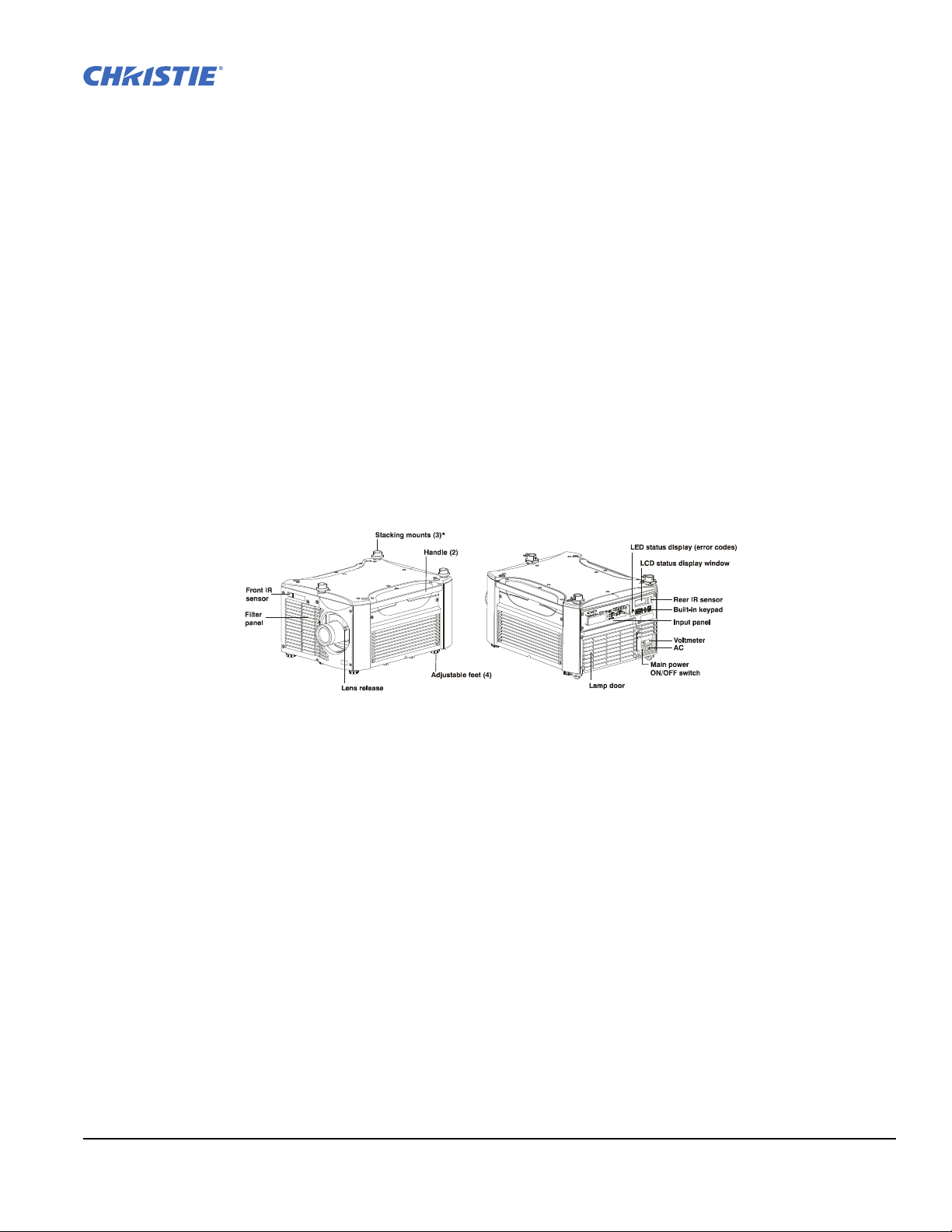
3 Operation
Figure 3-1 Basic Projector Components (* on Roadster series only)
This section describes the controls and switches used for basic projector operation once it is properly installed,
aligned and configured by a Christie accredited service technician. Please read through these pages before
using the projector for the first time. An understanding of projector features and how to access them will help
you to take full advantage of the capabilities of the projector within minutes.
NOTE: Installation involves locating the projector and adjusting it for use at that location. If you have not yet
installed the projector, refer to Section 2 Installation and Setup.
3.1 Projector Basics
It is recommended that you read this section and familiarize yourself with the components and the available
menu options before you begin using your projector for the first time.
Projector components and functions are illustrated below (Figure 3-1).
3.1.1 Zoom
Operated with the keypad, the internal optics of a motorized zoom lens rotates to adjust the size of the image
without moving the projector. Minimum and maximum image sizes depend on which zoom lens is installed.
Refer to Section 6 Specifications.
3.1.2 Lens Release
Push lens release to enable the lens to be rotated for removal.
3.1.3 Focus
Operated with the keypad, focus adjusts the sharpness of the image at the current throw distance.
3.1.4 Lens Offset
Operated with the keypad, vertical and horizontal offsets shift the lens and move the image up or down and left
or right. Refer to Section 2 Installation and Setup and Section 6 Specifications for ranges and other details.
Roadster, Matrix WU, Mirage S+/HD/WU User Manual 3-1
020-100002-06 Rev. 1 (04-2011)
Page 54

Section 3: Operation
3.1.5 Shutter and Iris
Operated with the keypad, closing the internal shutter blocks the lens internally and turns the image to OFF
(black). Enlarge the diameter of the iris (a.k.a. optical aperture) for optimized brightness; reduce the diameter
to optimize contrast ratio.
3.1.6 Eyebolts
• 2 eyebolts on bottom (factory-installed)—for attaching safety cables when hoisting inverted projectors.
• 4 eyebolts for top (separate)—for non-inverted hoisting.
NOTE: Two additional safety eyebolts required.
3.1.7 Handles
Handles are for brief hand transport only. Not used for hoisting, rigging, or as safety points.
3.1.8 Stacking Mounts / Stacking Legs
NOTE: Optional on Mirage models.
Used for stacking up to 3 projectors. Refer to Section 2 Installation and Setup for details.
Use Christie stacking mounts only.
3.1.9 Adjustable Feet
Turn the 4 adjustable feet to increase or decrease height and/or tilt as needed. For most installations the
projector will likely be slightly inclined to match the screen tilt – this reduces the amount of vertical offset
required. Refer to Section 2.3 Projector Position and Mounting for more details.
3.1.10 Filter Panel
The filter door is a louvered grille for air intake. Remove to access and replace air filter.
3.1.11 Lamp Door
The lamp door is a louvered grille for accessing and replacing the lamp module.
NOTE: Lamp replacement requires a qualified service technician.
3.1.12 Input Panel
The Input panel wires the projector to inputs (sources) and controllers such as PCs.
COMPOSITE/S-VIDEO INPUT - Accepts a composite video, DVI and S-Video signal from devices such as VCRs.
RGB INPUT - Accepts RGB and sync signals from devices such as computers, as well as composite video, S-
Video or YPbPr component signals.
RS-232 SERIAL INTERFACE (with Loop Through) - Allows one or more projectors to be remotely controlled by a
computer or controller.
RS-422 INTERFACE - Allows one or more projectors to be remotely controlled by an RS-422 compatible
computer or controller (such as the
3-2 Roadster, Matrix WU, Mirage S+/HD/WU User Manual
Two-Way Controller accessory).
020-100002-06 Rev. 1 (04-2011)
Page 55
3.1.13 AC Power Input and Monitoring
AC LINE CORD INPUT. Use the AC supply specified, and always use the line cord
recommended by Christie. Refer to
blower turns OFF or the LCD status reads Power OFF.
Table 3.1 AC Power Specifications
Model AC Power Specifications
ROADSTER S+12K/HD12K 200-240 VAC, 50-60 HZ, MAX. 12 AMPS @ 200VAC
M
ATRIX WU12 200-240 VAC, 50-60 HZ, MAX. 12 AMPS @ 200VAC
M
IRAGE HD12 200-240 VAC, 50-60 HZ, MAX. 12 AMPS @ 200VAC
IRAGE WU12 200-240 VAC, 50-60 HZ, MAX. 12 AMPS @ 200VAC
M
M
IRAGE S+12K 200-240 VAC, 50-60 HZ, MAX. 12 AMPS @ 200VAC
R
OADSTER S+16K 200-240 VAC, 50-60 HZ, MAX. 16 AMPS @ 200VAC
IRAGE S+14K 200-240 VAC, 50-60 HZ, MAX. 16 AMPS @ 200VAC
M
M
IRAGE S+16K 200-240 VAC, 50-60 HZ, MAX. 16 AMPS @ 200VAC
M
IRAGE HD18 200-240 VAC, 50-60 HZ, MAX. 20 AMPS @ 200VAC
IRAGE WU18 200-240 VAC, 50-60 HZ, MAX. 20 AMPS @ 200VAC
M
R
OADSTER S+20K/HD18K 200-240 VAC, 50-60 HZ, MAX. 20 AMPS @ 200VAC
M
IRAGE S+20K 200-240 VAC, 50-60 HZ, MAX. 20 AMPS @ 200VAC
Section 5 Troubleshooting. Before unplugging, wait until the main
Section 3: Operation
Do not attempt operation if the AC supply is not within the specified voltage and
power range. Use the specified line cord.
Voltme ter
Displays incoming voltage level reaching the projector.
Switch Breaker
The breaker/power switch on the rear panel serves two purposes:
• It is a power switch for the projector.
• It protects against excessive AC conditions (15A or more for Roadster S+12K/HD12K and Mirage HD12/
WU12/S+12K, 20A or more for Roadster S+16K and Mirage S+14K/S+16K, and 25A or more for Roadster
S+ 20K/HD18K and Mirage WU18/HD18/S+20K). If the projector is faulty or excessive AC is detected, the
breaker/power switch will “trip” to OFF in order to prevent damage. Try moving the breaker ON again. If the
breaker continues to trip OFF, this indicates a major fault and the AC problem must be resolved. Possible
causes might include shorts, damage to lamp cables, or excessive AC.
NOTE: This switch turns on the ballast only. It does not power up the projector or start the lamp. You must
press
on the keypad.
Roadster, Matrix WU, Mirage S+/HD/WU User Manual 3-3
020-100002-06 Rev. 1(04-2011)
Page 56

Section 3: Operation
3.1.14 Status Display (Error Codes) and Status Display Window
Two-digit Status/error Code Window
This LED (light emitting diode) display is adjacent to the built-in keypad. During normal operation, the
"POWER" light is steady yellow and indicates "ON". When the status of the projector changes, the LED
displays a 2-digit code number representing the projector's new status. In addition to the numeric readout, there
are 2 decimal points in the display: the right decimal point flashes when the projector receives a command and
the left point flashes when the projector sends a command.
LCD Status Display Window
Displays a text message describing the current system status (such as an error). During normal operation, this
display indicates Power ON and includes the frequencies of the vertical and horizontal syncs. The display also
shows if the On Screen Display (OSD or Menu system) is ON or OFF. The LCD displays the message “Power
Off” when the breaker is ON, but the lamp is OFF.
3.1.15 Keypads / Sensors
Wired Remote Connector
For optional tethered remote control of the projector.
Built-in Keypad
Alternative location for working with the projector.
Infrared Sensors
The infrared (IR) sensors on the front and rear of the projector receive infrared signals from the IR remote
which remotely controls the projector’s functions. For proper operation, ensure these sensors are not blocked.
3.2 Using the Keypads
Laser radiation is emitted from the laser diode in the remote. Do not look directly into
the beam of the remote.
Using one of the following keypads typically controls the projector:
• The Built-in keypad (Figure 3-2) located at the rear of the projection head
• The Remote keypad (Figure 3-3) for tethered or tether-less control (includes cable for connecting as a wired
remote)
While the built-in keypad or standard IR remote provides complete control of the projector, they differ slightly
in their arrangement of keys, and in which functions can be accessed directly with a key press rather than
requiring use of the Menu system. You may find one keypad more convenient than another for your specific
installation and application.
NOTE: The remote keypad has a single IR protocol and can be converted to a wired remote by connecting the
cable provided with the projector to the RCA jack labeled as REMOTE on the input panel.
3-4 Roadster, Matrix WU, Mirage S+/HD/WU User Manual
020-100002-06 Rev. 1 (04-2011)
Page 57
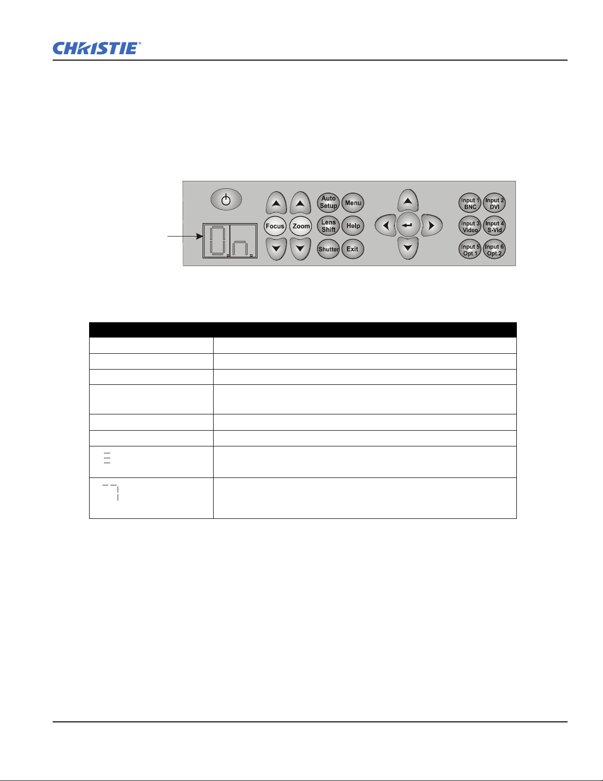
3.2.1 Built-in Keypad
LED Status
Display window
Figure 3-2 Built-in Keypad at Projector Rear
To control the projector when signals from a remote cannot reach the projector, use the projector's built-in
keypad (Figure 3-2). The 2 nearby Status windows provide feedback, indicating current status and activities of
the projector, (refer to Table 3.2). Because the built-in keypad has fewer keys than on the remote keypad,
certain projector functions are accessible only through the Menu system, rather than via a direct key press.
NOTE: The built-in keypad cannot be disabled.
Table 3.2 LED Status Display
LED STATUS DISPLAY DESCRIPTION
- - AC POWER SUPPLIED, PROJECTOR OFF
O
N PROJECTOR ON
LC L
LP
SH CLOSED SHUTTER
# # SYSTEM WARNING OR ERROR HAS OCCURRED
Section 3: Operation
ENS CALIBRATION IN PROGRESS
L
AMP HAS REACHED DEFINED "LAMP LIMIT". REFER TO Section 3.8
Working with the Lamp
COOLING DOWN (ROTATING HORIZONTAL BARS)
Roadster, Matrix WU, Mirage S+/HD/WU User Manual 3-5
020-100002-06 Rev. 1(04-2011)
P
OWER TO OFF STATE OR POWERING UP (SEGMENTS SPINNING CLOCK-
WISE)
Page 58
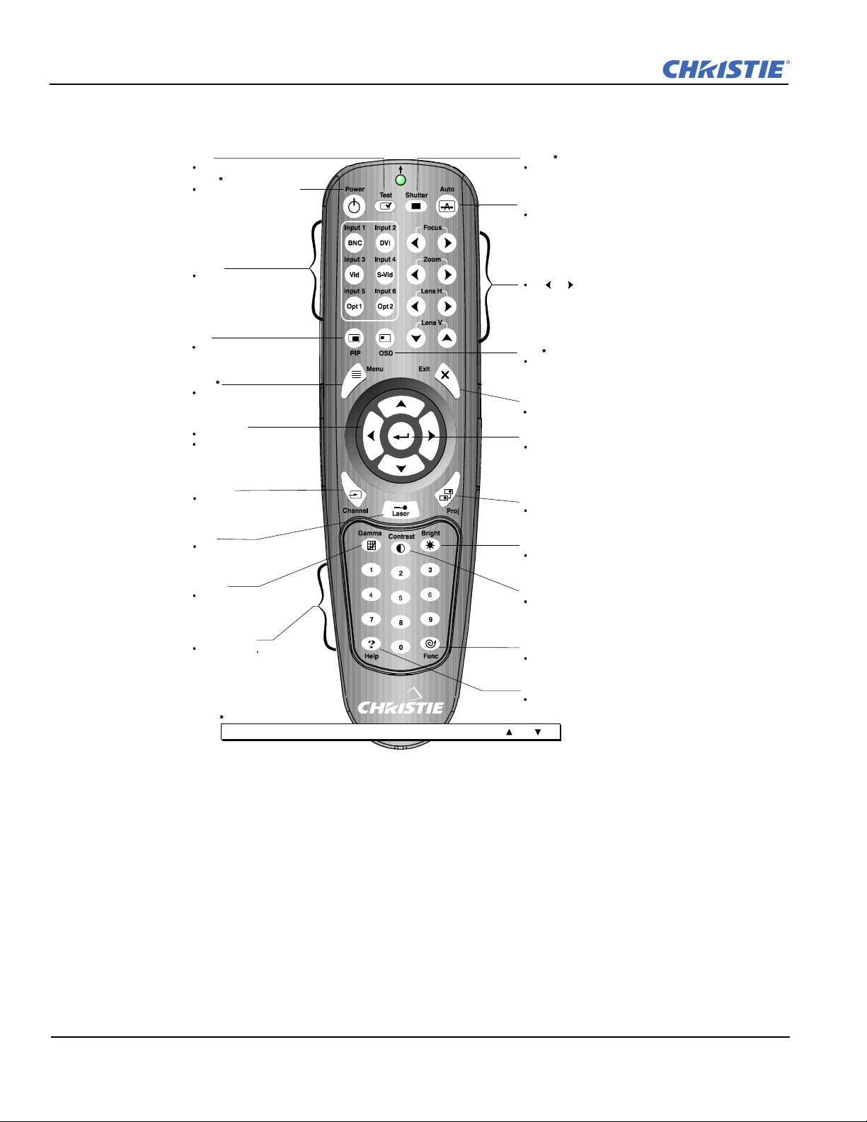
Section 3: Operation
Te st
Display a test pattern
Power
Turn projector ON or OFF
Display from this source
NOTE:
If PIP is ON, Input
keys affect the PIP window
only.
Turn picture-in-picture
ON or OFF
NOTE:
N/A on WU Models.
Displays menus
Inputs
PIP
Menu
Arrow Keys
Adjust a setting up or down
Navigate within a menu
Select channel (setup)
Activate laser pointer
at front of keypad
Channel
Laser
Gamma
Adjust mid-range levels
Number Keys
Enter a number, such
as channel, value, etc.
NOTE:
Can be set to select
inputs if desired
TOGGLE KEYS=
Press and to t oggle or press twice to toggle or press and release, followed by ON or OFF
hold
Help
Display context
sensitive help (toggle)
Enter special code
such as color enabling
Func
Contrast
Adjust difference
between light/dark
Bright
Adjust amount of
light in image
Projector
Select a projector in multiprojector installations
Enter
Select a highlighted menu item;
change or accept a value
Exit
Return to previous menu level
OSD
Use to hide or show menus
Lens Functions
Use and keys to
adjust parameters
Auto
Optimize image automatically
Open or close the shutter
Shutter
Figure 3-3 Remote Keypad
3.2.2 IR Remote
The IR remote controls the projector by way of wireless communications through a battery-powered infrared
(IR) transmitter. Use the IR remote the same way you would use a remote supplied with a TV or VCR. When
making key presses, direct the standard IR remote either toward the screen or toward the front or rear IR
sensors on the projector.
NOTE: For improved reception, use an optional remote IR sensor to route the signal via a phone cable
plugged into the wired port labeled
The “Brick” style rental staging/standard IR remote, typically used with Roadster models, is shown in Figure
3-4. It has no laser pointer, but includes 3 additional keys:
• SWAP key for use with PIP functions
• BACKLIGHT key for lighting keys
3-6 Roadster, Matrix WU, Mirage S+/HD/WU User Manual
•Direct INPUT key used with the numbered keypad to switch from one input to another
REMOTE. Refer to Figure 1-2.
020-100002-06 Rev. 1 (04-2011)
Page 59
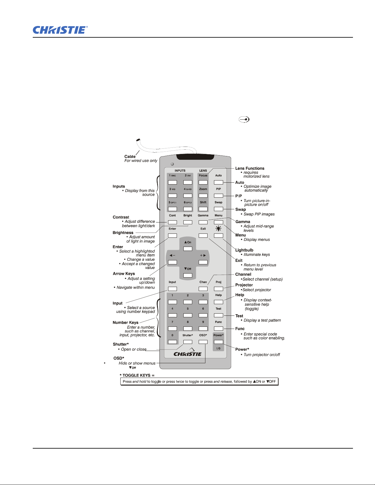
3.2.3 Wired Remote
the shutter
Press OSD to turn Off
Use to
Figure 3-4 Standard IR Remote
You can convert the IR remote into a wired remote keypad using the cable provided with the projector.
Connect one end into the remote and the other to the mini stereo connector on the input panel labeled as
REMOTE.
The wired remote is recommended when:
• The built-in keypad is inaccessible
• The lighting conditions are unsuitable for proper IR transmission
NOTE: Leave the batteries in the wired remote for the laser key ( ) to work.
Section 3: Operation
Roadster, Matrix WU, Mirage S+/HD/WU User Manual 3-7
020-100002-06 Rev. 1(04-2011)
The "Brick" style rental staging - Standard IR Remote, typically used with Roadster models, is shown in
Figure 3-4. It has no laser pointer, but includes three additional keys: the S
B
ACKLIGHT key for lighting keys, and direct INPUT key used with the numbered keypad to switch from one
WAP key for use with PIP functions,
input to another.
Page 60
Section 3: Operation
Te st
Auto
3.2.4 Guide to Keypads
• Press keys one-at-a-time; there are no simultaneous key combinations required.
NOTE: Three keys: P
• Hold the A
RROW keys down for continuous adjustment/movement in one direction. In serial networks, pause
OWER, SHUTTER ,and OSD. Press key once. Refer to Figure 3-4.
briefly between adjustments to ensure that more distant projectors can "keep up" with the commands.
• If you press any key while the projector is still responding to the previous action, such as during power-up,
the second key press may not take effect.
3.2.5 Keypad Commands
Specific keypad commands are explained below.
Power ON/OFF
• Press and hold briefly to toggle the projector ON or OFF with a single keystroke or press twice.
• Press and release followed immediately by the key (ON) or the key (OFF) to guarantee the
correct toggle. This is useful if you are unsure of the present state.
NOTES: 1) After powering down, the lamp cooling fan remains on for approximately 5 minutes to cool the
lamp. 2) It is a good idea to avoid turning a projector back ON until it has been OFF for several
minutes. Hot re-strikes of the lamp may reduce lamp life.
Test
Press to scroll through the projector's internal test patterns. When a test pattern is up, use and
to scroll through the patterns without going back to the Input.
Auto
Press to initiate an automated process in which the projector optimizes critical display parameters such
Se t u p
as size, position, pixel tracking, etc., for the current unlocked channel. These parameters are listed in Table 3.3.
An Auto Setup can save time in perfecting a display, and you can further modify the settings as desired.
NOTE:
For WUXGA models a window will display, "Do Auto Setup, all except UXGA" and "Do Auto Setup,
all except WUXGA
signal is WUXGA, choose, "
". If your signal is UXGA, choose "Do Auto Setup, all except WUXGA". If your
Do Auto Setup, all except UXGA". The default is "all except WUXGA".
This is only used and relevant for analog UXGA or WUXGA.
Table 3.3 Auto Setup
What an “Auto Setup” Does
OPTIMIZES: SETS TO DEFAULT:
SIZE AND BLANKING AUTO INPUT LEVEL (OFF)
V
ERTICAL STRETCH DETAIL (IF VIDEO SOURCE)
OSITION FILTER
P
INPUT LEVELS LUMA DELAY
NOTE: You must have an unlocked channel present to use AUTO SETUP.
3-8 Roadster, Matrix WU, Mirage S+/HD/WU User Manual
020-100002-06 Rev. 1 (04-2011)
Page 61

Section 3: Operation
Channel
Chan nel
Press to select a specific source setup (channel) defined, and stored in projector memory.
Once you enter a 2-digit channel number (or, if there is a list displayed, highlight it, and press ), the
display will automatically change and update according to the numerous setup parameters defined for that
channel. Note that a new channel is automatically created if you adjust an image from a new source.
Chan nel
NOTE: The key behavior during a presentation depends on whether or not the Display Channel List
option is enabled in the Menu Preferences menu. You can choose to use a scrollable list of channels
Chan nel
when you press , or you may prefer to enter the desired channel number "blind", i.e., without onscreen feedback. Refer to Menu Preferences in Section 3.6.1 System Configuration (General Settings)
discussed later in this section.
Input 1
Inp ut 1
Press to display from the data input source connected to BNCs labeled INPUT 1. If PIP is enabled,
Inp ut 1
pressing will change the PIP source.
Input 2
Input 2 Input 2
Press to display from the DVI source connected to INPUT 2. If PIP is enabled, pressing will
change the PIP source.
Input 3
Input 3
Press to display from the composite video source connected to INPUT 3. If PIP is enabled, pressing
Input 3
will change the PIP source.
Input 4
Input 4 Input 4
Press to display from the S-video source connected to INPUT 4. If PIP is enabled, pressing will
change the PIP source.
Input 5
Input 5
Press to display from the INPUT 5 interface module installed in the Option 1 slot.
Input 5
If PIP is enabled, pressing changes the PIP source. If there are 2 inputs connected here, such as if the
Dual SD/HD-SDI module is installed, the second input (B) is considered INPUT 7. Press to access
Input 5
INPUT 7 as follows:
• While displaying from INPUT 5, press again. This switches to INPUT 7.
Input 5
Input 5
• While displaying from any input other than the Dual SD/HD-SDI Module, press . This switches to
either INPUT 5 or INPUT 7, depending on which of the Dual Module inputs (A or B) was last used. Press
Input 5
again to display from the other Dual SD/HD-SDI Module input.
Roadster, Matrix WU, Mirage S+/HD/WU User Manual 3-9
020-100002-06 Rev. 1(04-2011)
Page 62

Section 3: Operation
n
n
PIP
n
Brig ht
Con tra st
Input 6
Input 6
Press the
enabled, press INPUT 6 to assign it as the PIP source. If the Dual SD/HD-SDI Module is installed here, and
there are two inputs connected, its second input (B) is considered INPUT 8. Or, if you are using the built-in
keypad or the remote keypad, neither of which have a separate
follows:
key to display from the INPUT 6 interface module installed in the Option 2 slot. If PIP is
Input
key, press INPUT 6 to access INPUT 8 as
• While displaying from INPUT 6, press again to switch to INPUT 8.
• While displaying from any input other than the Dual SD/HD-SDI Module, press . This switches to
Input 6
Input 6
either INPUT 6 or INPUT 8, depending on which of the Dual SD/HD-SDI Module inputs (A or B) was last
used. Press
Input 6
again to display from the other Dual SD/HD-SDI Module input.
Input (Standard IR Remote Only)
Input
Enter (where
n = 1, 2, 3, 4, 5, 6; 7 and 8 are optional) as an alternative method for selecting which
source to display. The 6 source locations are identified with Input numbers on the projector's Input panel. The
last two, 7 and 8, require the Dual SD/HD-SDI Module be installed in either of the option slots.
If PIP is enabled, changes the PIP (secondary) image source, and changes the main
Input
Input
(primary) image source.
NOTE: Key behavior depends on whether or not the Display Channel List option is selected in the Menu
Preferences menu. You can choose to have on-screen feedback when you press , or you may prefer to
enter the desired source location "blind", i.e. without on-screen feedback. Refer toMenu Preferences
in Section 3.6.1 System Configuration (General Settings).
Brightness
Press to increase or decrease the amount of black in the image. Use the and keys until you
reach the desired level of contrast. For best results, start high and decrease so that dark areas do not become
black (i.e., "crushed"). Conversely, overly high brightness changes black to dark gray, causing washed-out
images. Refer to Section 3.5.3 Image Settings Menu.
NOTE: Always adjust Brightness before
Contrast.
Contrast
Press to change the amount of white in your images. Use the and keys until you reach the
desired level of contrast. For best results, start low and increase so that whites remain bright, but are not
distorted or tinted, and that light areas do not become white (i.e., "crushed"). Conversely, low contrast causes
dim images. Refer to Section 3.5.3 Image Settings Menu.
Gamm a
Gamma
NOTE: This is the same as "Gamma" in the Image Settings menu.
"Gamma" determines what gray shades are displayed between minimum input (black) and maximum input
(white) for a given amount of signal. The proper setting helps maintain optimized blacks and whites while
ensuring a smooth transition for the "in-between" values utilized in colors and grays. Thus, unlike brightness
3-10 Roadster, Matrix WU, Mirage S+/HD/WU User Manual
020-100002-06 Rev. 1 (04-2011)
Page 63

Section 3: Operation
Men u
Swap
and contrast settings controls, the overall tone of an image can be lightened or darkened without changing the
two extremes, and your images will be more vibrant yet with good detail in dark areas.
The normal Gamma Table setting of 2.2 is correct for most signals and conditions. If excess ambient light
washes out the image and it becomes difficult or impossible to see details in dark areas, lower the gamma
setting to compensate. This will improve contrast ratio while maintaining good details for blacks.
Menu
Press to enter or exit the projector's Menu system.
NOTE: Refer to Appendix E: Menu Tree, which allows you to quickly locate and navigate to a specific menu,
and associated options/submenus.
OSD (On-Screen Display)
OSD
Press + the key to hide the projector's Menu system during use.
To see the Menu system again, do one of the following:
OSD
• Press and hold briefly
• Press and release followed immediately by the key
OSD
• Press twice quickly
OSD
Invisible menus are fully functional, enabling "hidden" access to numbered features and image adjustments by
entering the corresponding sequence of key presses on the keypad.
NOTES: 1) With the OSD "ON", you can still hide error messages and slidebars by disabling these options in
the Menu Preferences menu.
PIP (Picture-in-Picture)
Press to enable and disable Picture-in-Picture. PIP enables you to display two different images
simultaneously, typically a smaller "secondary" image within a large "primary" background. When a menu
control or slidebar is present, press to toggle the current function to affect the other image.
NOTE: Disable PIP and Best Switching for Interlaced sources > 35 kHz.
Swap
Press to swap the current picture-in-picture relationship so that the primary image becomes secondary,
and the secondary image becomes primary.
NOTES: 1) This key is available on the "Brick" rental staging - Standard IR remote only. Alternatively, a
swap can be accessed in the Menu system. 2) Requires PIP enabled.
Shutter
Sh utter
Press and hold the key briefly to toggle the internal mechanical shutter blade closed or open with a single
keystroke.
Sh utter
Press and release the
key followed immediately by the key (shutter ON; closed) or the key
(shutter OFF; open) to guarantee the correct toggle (useful if you are unsure of the present state).
Roadster, Matrix WU, Mirage S+/HD/WU User Manual 3-11
020-100002-06 Rev. 1(04-2011)
Page 64
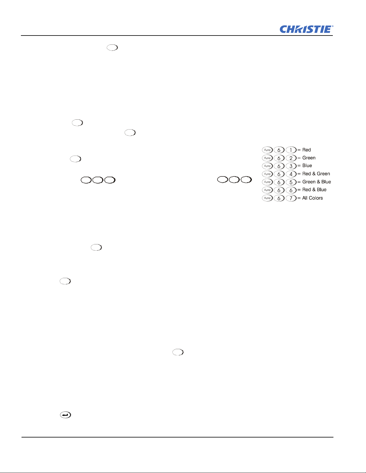
Section 3: Operation
Fu n c Fu n c
Fu n c
Fu n c
Fu nc
Fu n c
Pr o j
Pr o j
Alternatively, press the key to toggle from the present ON/OFF state. A closed shutter blanks the display
(turns it to black). Close the shutter to mute all display while maintaining access to projector functions.
Opening the shutter restores the image.
NOTES: 1) The status of the shutter is shown in the LCD display window at the rear of the projector. 2) The
shutter is open upon power-up.
Function Key
If You are Within a Menu
Sh utter
Using the key for special tasks within the Menu system is noted with the appropriate topic elsewhere in
Section 3. For example, press in the Channel Setup menu to enable deletion or copying of a channel.
If You are Within a Presentation
Press the key followed by a 2-digit number to enable a specific color or
colors in the display (see right).
For example, will display only red and green data,
64
67
will display all color data. Eliminating one or more colors can help with certain
diagnostics and setups, such as when accurately overlaying one image on top of
another when stacking projectors.
Defining Other Uses
Through ASCII messaging on a PC, you can also create special user functions for keys 1 - 5 and 7 - 9, and
others.
For example, the key can be programmed to trigger RTEs (Real Time Events) or to display custom
menus. Refer to the separate Christie Serial Communications publication.
Projector
Press to access a specific projector within a group of projectors or to confirm if the local projector is
listening. The number in the "Enter Number" window indicates which projector is currently listening to
commands, and will match the projector number that has been defined in the Menu Preferences menu.
The "Projector" check box (read-only) shows whether or not the projector physically connected to a keypad are
listening to commands from that keypad. A check mark means that connected projector is listening; if there is
no check mark, you are communicating with a different projector.
To control a specific projector with the keypad, enter the 3-digit number assigned to the projector you want to
use. If you switch to a projector other than the one you are currently using, the check mark will disappear.
To broadcast to multiple linked projectors, press twice without entering a projector number.
NOTE: 1) Keypad commands will affect all projectors in the chain. 2) The "Broadcast Keys" option in the
Communications menu must be selected for only one (any) projector in a serial network. The keypad
in use must be OFF (disabled) for the remaining projectors. Refer to Section 2.11 Keypad and Remote
Protocols and Conversion, and Section 3.6 Adjusting System Parameters and Advanced Controls.
Enter
Press to select a highlighted menu/ option item, to toggle a check box, or to accept a parameter
adjustment, and return to the previous menu or image.
3-12 Roadster, Matrix WU, Mirage S+/HD/WU User Manual
020-100002-06 Rev. 1 (04-2011)
Page 65

Exit
Exit
Exit
Focus
Zoom Lens H Lens V
Lens
Lens
Figure 3-5 Entering the Menu System
Men u
Press to return to the previous level, such as the previous menu.
Section 3: Operation
NOTE: does not save changes within text editing boxes (including number editing of a slidebar value)
or within drop-down lists. It acts as "Cancel" in these cases.
Arrow Keys
Use the keys to change a slidebar value or to select a different option within
a drop-down list without having to first scroll through options. These keys also jump to
the next page in long menus. Refer to Section 3.3.6 Editing Text.
Use the keys to navigate within a menu, drop-down list, or text box. Use in
combination with P
OWER, SHUTTER and OSD keys to force the corresponding state.
See details provided on the back of the IR remote keypad.
Lens Focus, Zoom and Lens H, Lens V
Shift
Use , , , , and with their corresponding Arrow keys to adjust the lens for optical
sharpness, size, and position. Note that Z
Shift
NOTES: 1) The key, when combined with the Arrow keys on the built-in keypad is the same as using the
L
ENS H and LENS V keys on the remote. 2) On the "Brick" rental staging - Standard IR remote, use the
OOM requires a zoom lens.
3 lens keys with the arrow keys.
Laser
NOTE: Not available on the "Brick" rental staging - Standard IR remote.
Press to activate the laser pointer, and direct the remote at the screen to highlight an area with a light
beam (dot). The closer you are to the screen the brighter the laser beam appears. The laser pointer works best
with reduced ambient lighting.
Backlighting
NOTE: Only available on the Standard IR remote.
Press the key to illuminate the keys on the remote without sending a command to the projector.
3.3 Navigating the Menus
Most of the controls for the projector are accessed from within
the projector's Menu system. There are several groups of
related functions, with each group selectable from the Main
menu as shown at right.
Press at any time to display this Main menu. See Figure
3-5.
On the remote keypad, either enter the number corresponding
to the Function menu you wish to access, such as 2 for the
Image Settings menu.
Roadster, Matrix WU, Mirage S+/HD/WU User Manual 3-13
020-100002-06 Rev. 1(04-2011)
Page 66

Section 3: Operation
Exit
Men u
Help
Help
Figure 3-6 Context-Sensitive Help
Help Help Exit
Or use the keys on either the built-in keypad or a remote to highlight the desired option, then press
. The corresponding Function menu or drop-down list of further options will then appear.
With a Function menu displayed, navigate in a similar manner, enter a Menu option number for any numbered
option, or use the keys to highlight the desired option, and then press . Extra long menus have a
scroll bar on the right-use the Arrow keys to access the remainder of the menu. Locked items or items that do
not pertain to the current action or condition appear dimmed and cannot be selected.
NOTES: 1) If there is no signal present, all source-dependent adjustments are disabled. 2) After 15 minutes of
inactivity, the projector saves and leaves the Menu system, and returns to the presentation. 3) The
Status menu is read-only.
When finished with a Function menu, do one of the following:
• Press to return to the previous screen
• Press to leave the Menu system and return to the presentation
3.3.1 On-line Help
If at any time you are uncertain what to do next, press to display summary information about the current
menu or highlighted option.
Press again to exit. In addition, a line of "hint" text is included at the bottom of some menus. See Figure
3-6.
From presentation level, press to access general Help Topics (Figure 3-7). Scroll as necessary within a
topic.
Press or to return to your presentation.
3-14 Roadster, Matrix WU, Mirage S+/HD/WU User Manual
020-100002-06 Rev. 1 (04-2011)
Page 67

3.3.2 Time-outs
Figure 3-7 Assessing General Help Topics
PIP
If a slidebar, menu, or message is displayed, you have limited time in which to make a keypad entry before the
projector returns to presentation level HELP and the graphic disappears. These time-outs may vary depending
on what is displayed.
3.3.3 Global Icons
Section 3: Operation
Menu options that include this icon apply universally to any incoming signal.
3.3.4 PIP Icon
Menu options that include this icon apply to PIP (secondary) images only.
3.3.5 Using Slidebars and Other Commands
Most of the Function menus allow you to change settings by using slidebars, check boxes, and drop-down
lists. To select a slidebar, toggle a check box status, or view a drop-down list, do one of the following within
the function menu:
• Enter the Menu option number corresponding to the setting you wish to change (for example, press 1 + 3
from the Main menu to select Ver tica l St retc h in the Size & Position menu).
• Move to highlight the desired option, and press .
• Or move the highlight to the option desired, and press the keys to adjust immediately.
• Or bypass the menus entirely, and use a single key to immediately access an adjustment during your presentation
NOTE: Applies only to options having their own key, such as Contrast, Brightness, Gamma, etc.
For "blind" access, hide the entire Menu system (refer to OSD key, above) and/or direct slidebars activated by
their own key (such as CONTRAST, BRIGHTNESS, etc.). Control by using the proper key press or numerical
sequence of key presses.
When using PIP images, use the key to adjust the image.
Once selected, change the settings as desired (see below). Changes take effect immediately and are saved upon
exit from all menus, or after 15 minutes.
Roadster, Matrix WU, Mirage S+/HD/WU User Manual 3-15
020-100002-06 Rev. 1(04-2011)
Page 68

Section 3: Operation
Exit Cont
Exit Exit
Slidebars in Menus
The current value for a given parameter, such as size or vertical stretch, appears to the left of its slidebar icon
(Adjustment window). This number often expresses a percentage, or it may have units associated with it (such
as pixels, degrees Kelvin, etc.), depending on the specific option.
Press the keys to gradually adjust the setting . Both the number and the length of the bar
change accordingly. Hold for continuous adjustment.
Or press to activate a slidebar text box for a specific number entry via the keypad, and then press to
save (or press to cancel).
"Direct" Slidebars
For quick access, you can access Gamma, Brightness, and Contrast slidebars without traveling through the
Menu system. For example, simply press to immediately display the same CONTRAST slidebar
accessed with the Contrast option in the Image Settings menu.
Use the Arrow keys to adjust a direct slidebar, or press and type a specific number from the built-in
keypad or standard IR remote, then press or the keys to save (or to cancel). When you
are done, press to save and return to your presentation.
NOTES: 1) You can still adjust a direct slidebar as usual if the display is turned OFF (refer toOSD (On-
Screen Display) or theMenu Preferences) except the slidebar is not visible. 2) A direct slidebar
disappears if it is not used within 5 seconds.
Check Boxes
Conditions are present if its adjacent check box contains a check mark. To select or clear a check box, simply
highlight and press , or highlight and press the key to “Select” or key to “Clear”. If a check
box is numbered, simply enter its number to immediately toggle (“Select” or “Clear”) the check box.
Drop-down Lists
To view a drop-down list of options available for a given parameter (labeled with a inverted triangle shaped
icon), you can either:
• highlight the parameter, and press
•enter the Menu option number.
Press the keys to navigate within the list. Press to select a highlighted option from the list, if
desired. See Figure 3-8.
3-16 Roadster, Matrix WU, Mirage S+/HD/WU User Manual
020-100002-06 Rev. 1 (04-2011)
Page 69

Section 3: Operation
1.
2.
3.
4.
5.
6.
7.
8.
9.
0.
Baud Rate for RS232
Baud Rate for RS422
Projector
Network Routing
Ethernet Settings
Broadcast Key
Backlight
Front IR
Back IR
Wired Keypad
115 200
115 200
004
Separate
Off
Any
Any
Communications
Separate
RS232 and RS422 joined
Ethernet joined
All joined
RS232 and
1.
2.
3.
4.
Exit Fu n c Fu n c
Figure 3-8 Example of drop-down List
Or, if you prefer to quickly scroll through an option list without using its drop-down list, you can use the
keys to locate and highlight the desired option.
NOTES: 1) Press
while in a drop-down list to cancel any change(s) and exit.
3.3.6 Editing Text
Activate the Edit Window
To enter or edit text, highlight the desired parameter (such as a Channel name) and press to activate its
adjacent Edit window. Any previously entered text appears with its first character highlighted in a square
cursor, signifying that this character is the starting point for editing. See Figure 3-9.
Navigate Within the Edit Window
Press the key to move the cursor forward or the key to move the cursor backwards, character by
character, as desired.
the keys to jump between pages in an extra long drop-down list. 2) Press
Figure 3-9 Entering Text
Add or Delete a Character or Space
To insert a space at the cursor location, press + the key. To delete a highlighted character (or space),
press + the key.
Roadster, Matrix WU, Mirage S+/HD/WU User Manual 3-17
020-100002-06 Rev. 1(04-2011)
Page 70
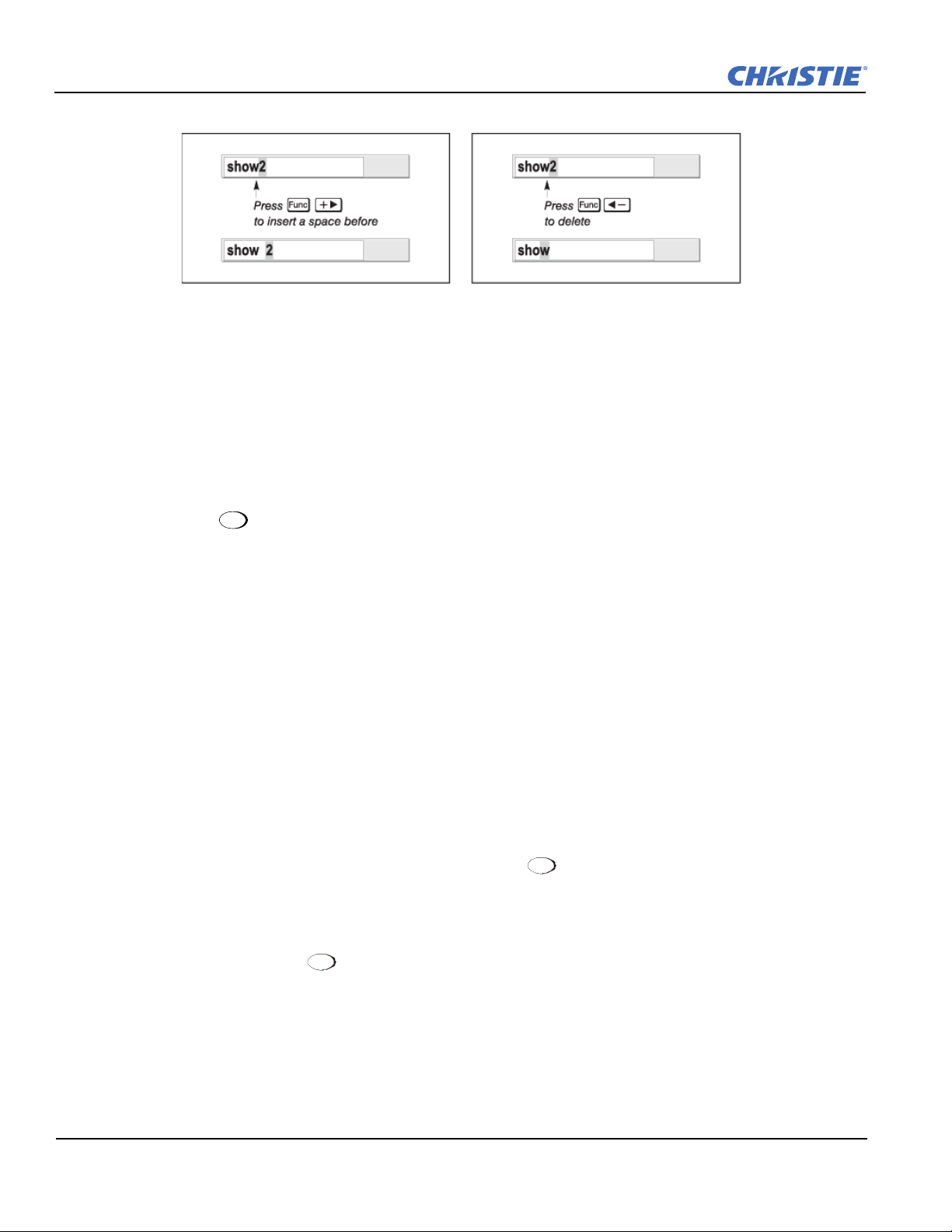
Section 3: Operation
Exit
3.3.7 Editing Numerical Values
Enter numbers directly from the built-in keypad or standard IR remote in order to specify numbers representing
projectors, channels (source setups), or slots. As each digit is entered, it displays and the cursor moves on.
Note that Channels are assigned 2-digit numbers. For example, if you enter only a single digit (such as "7") for
a channel number, the channel automatically changes to "07". Enter "07" to utilize this channel.
NOTES: 1) Once you enter the first digit, this digit over-writes the current entry. 2) If you press any non-
numbered keys, the number entered up to that point is accepted, and updated as the new value. 3)
Press to cancel editing of numerical values.
Figure 3-10 Editing Text
3.4 Using Inputs and Channels
NOTE: Refer to Section 2 Installation and Setup, for a full explanation of how to connect sources to the
projector.
The projector stores and automatically recalls up to 50 different channels (source setups) for a variety of inputs.
This memory feature allows you to define and conveniently use a wide variety of customized setups rather than
having to repeatedly re-configure the projector for different presentations. Depending on what you have
defined, each physical source connection (i.e., input source to the projector) can have several different channels
associated with it.
3.4.1 Do I Select an Input or a Channel?
Input
An Input is a source physically connected to the projector. describes the source signal according to
which Input slot (side panel) it is connected.
Switching Inputs
Input
Press the appropriate direct key (1 to 6) to quickly display 1 of the 6 inputs connected at the side of the
projector.
The image displays according to the following:
Input
If it is the first time you have used the source/input (or if you used the input, but did not define a channel by
adjusting anything), the projector recognizes the new input signal based on its frequencies and polarities, and
automatically displays an image according to default settings for such a signal. In general, the image from the
3-18 Roadster, Matrix WU, Mirage S+/HD/WU User Manual
020-100002-06 Rev. 1 (04-2011)
Page 71

Section 3: Operation
Chan
Chan
Chan
Chan
new source is as large as possible without losing its aspect ratio. This and other default image settings depend
on the incoming source.
If you used the source once before and changed a display parameter such as Contrast, V-Position, etc.,
then a channel is automatically created and still exists in projector memory (see below).
Input
Using an key automatically recalls this channel (along with all associated setup parameters) and updates
the display accordingly.
If more than 1 channel exists for the input, the image displays according to the setup parameters for the first
channel with matching characteristics.
If PIP is enabled, an input key changes the PIP (secondary) image only. To switch the main input, use the
keypad number keys with "Numbers Select Main Image" activated.
NOTE: Inputs 7 and 8 require the Dual SD/HD-SDI module in either of the projector's option slots. For their
selection, refer to Section 3.2 Using the Keypads. For more information on numbers to select main
image, refer to Section 3.7 Working with PIP or Seamless Switching.
Channel
A Channel is a collection of measurements, locations and settings that tailor the display of a signal to your
specific needs. Since source types and applications can vary greatly, you likely want to adjust and define a
wide variety of parameters, such as Brightness, Contrast, Size, etc., in order to customize and optimize the
display from or for a particular source. For example, the display settings you choose for a VCR source may be
very different from those you choose for a high resolution computer source, or 1 signal may simply vary from
another signal used previously through the same input location. Once you have adjusted a display parameter,
such as pixel tracking or contrast, all current settings are collectively stored in the projector's memory as a
unique 2-digit Channel, such as "09".
You can have numerous distinct channels available for the same input, any of which can be selected by using
the key on the keypad, followed by the 2-digit channel number.
Figure 3-11 Channel List
Shown above is a sample list of channels available when you press the key. This is typically called the
“Channel list”.
NOTE:
The key may display a channel list or not, depending on what you have defined for "Display
Channel List". Refer toMenu Preferences in Section 3.6.1 System Configuration (General Settings).
In order to access channels by using the key on the remote, you must first create the channels.
Roadster, Matrix WU, Mirage S+/HD/WU User Manual 3-19
020-100002-06 Rev. 1(04-2011)
Page 72

Section 3: Operation
Chan
Men u
3.4.2 Creating a New Channel (Automatic)
To use a new input source with the projector, a new channel must be added to the projector memory so that the
projector responds properly to an input signal from that source in the future. A new channel can be created
automatically, as described here, or it can be copied from an existing channel, and then edited as necessary
(refer to Section 3.4.4 Copying or Deleting Channels later in this section).
When you select a direct Input (Input 1, Input 2, Input 3, Input 4, Input 5, or Input 6), any existing channels
in the projector are searched for matching input and signal parameters. If no match to the incoming input signal
is found in currently-defined channels, a new channel is temporarily created based on factory-defined defaults
for this type of signal. The channel number assigned is the lowest available number from 01-99.
NOTES: 1) An automatic channel is discarded unless 1 or more of its parameters are changed, and it does not
appear in the channel list (see below). 2) If two channels have the same distinguishing source
characteristics except for the reversal of sync connectors (i.e., H-sync and V-sync, are switched), they
are still defined as distinct channels. 3) You cannot define a new channel without an incoming signal.
If the incoming signal does match an existing channel, the image is set up and displays as usual, according to
the parameters currently defined for that channel.
Using a Channel
You can normally select a channel at any time by pressing . Refer to Figure 3-12. If you want to prevent a
channel from appearing in this list, you must edit the channel as described in Section 3.4.5 Editing a Channel
Setup later in this section. Such a channel can still be selected by entering its number as shown below.
Figure 3-12 Selecting a Channel
NOTES: 1) The current channel is highlighted upon entering the channel list, or, if this channel is not
displayed here, the first channel in the list is highlighted. 2) Channels created automatically do not
appear in the channel list unless a parameter for the channel has been changed.
3.4.3 What Channels are Defined So Far?
All available channels are listed in the Channel Setup menu, which describes how each channel can be
accessed and which serves as the gateway for editing, copying, and deleting channels.
From the presentation level, press to display the Main menu. To display the Channel Setup menu:
• Move the highlight to the Channel Setup option, and press
•Press 3
The Channel Setup menu appears (see Figure 3-13) with the active channel highlighted.
3-20 Roadster, Matrix WU, Mirage S+/HD/WU User Manual
020-100002-06 Rev. 1 (04-2011)
Page 73

Section 3: Operation
Chan
Figure 3-13 All Channels Appear in Channel Setup Menu
What Appears in the Channel Setup Menu?
This menu lists all channels currently defined and indicates where they connect on
the projector's side input panel. The far left column lists channel numbers
currently defined. The values in the far right columns indicate horizontal and
vertical frequencies or if someone has defined a name for this channel, it appears
here instead. Remaining columns contain details pertaining to each channel setup,
such as the switcher number (always 0 = projector), slot location (01-06; 7 + 8 with optional SDH), a variety of
icons indicating access to each channel, and an abbreviated description of each signal type. Refer to Section
3.4.5 Editing a Channel Setup for details.
NOTE:
If you have more than a handful of channels, use the and keys to see the remaining
channels not visible in the initial display of channels.
Signal Type
Either Channel list, whether the key list or the Channel Setup menu, identifies signal types in a
shortened form as defined below. These description codes indicate what signal information the projector uses
to identify a match for a given channel, and are preceded by either an "i" (interlaced signals) or "p"
(progressive signal"). Refer to Figure 3-13.
Table 3.4 Abbreviations for Signal Type
Codes Signal Type
4WH COMPOSITE (4 WIRE) ON HC INPUT
4WV COMPOSITE (4 WIRE) ON V INPUT
SG SYNC-ON-GREEN
5W SEPARATE H,V
5WR S
SVID S-VID
CVID COMPOSITE VIDEO
DIG DIGITAL
Functions within the Channel Setup Menu
EPARATE H,V SWAPPED
To copy, delete or edit a channel, highlight the desired channel in the Channel Setup menu and do 1 of 2
things:
Roadster, Matrix WU, Mirage S+/HD/WU User Manual 3-21
020-100002-06 Rev. 1(04-2011)
Page 74
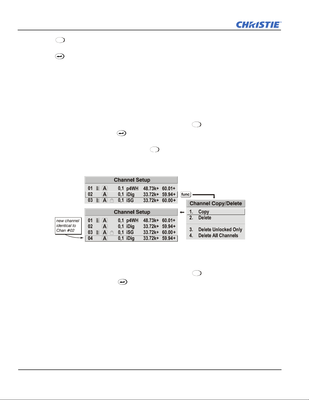
Section 3: Operation
Fu n c
Fu n c
Exit
Fu n c
• Press if you want to copy the selected channel or delete one or more channels. See Section 3.4.4 Copy-
ing or Deleting Channels or refer to To Delete a Channel.
• Press if you want to edit a channel’s setup (i.e., non-image related parameters) for the selected channel.
Refer to Section 3.4.5 Editing a Channel Setup.
3.4.4 Copying or Deleting Channels
To C o p y a C h a n nel
Making a copy of a channel is a quick way to duplicate a channel that contains most of the settings you need
without creating a new one from scratch. This then allows you to adjust the settings specific to the new
presentation required.
Highlight the desired channel in the Channel Setup menu, and press to go to the Channel Copy/Delete
submenu. Select "Copy", and press . A new channel will be created. It is identical to the original channel,
but it is identified with the next available number from 01-50. Refer to Figure 3-14. If you change your mind
and do not want to copy the current channel, press to cancel and return to the previous menu. Copying
channels is a quick method for creating numerous channels, each of which can then be edited and adjusted for
a variety of presentations in the future.
Figure 3-14 Copying A Channel
To D e l e t e a C h a nnel
Highlight the desired channel in the Channel Setup menu, and press to open the Channel Copy/Delete
submenu. Select "Delete" and press . A confirmation window appears to confirm that you want to delete
this channel. See Figure 3-15.
3-22 Roadster, Matrix WU, Mirage S+/HD/WU User Manual
020-100002-06 Rev. 1 (04-2011)
Page 75
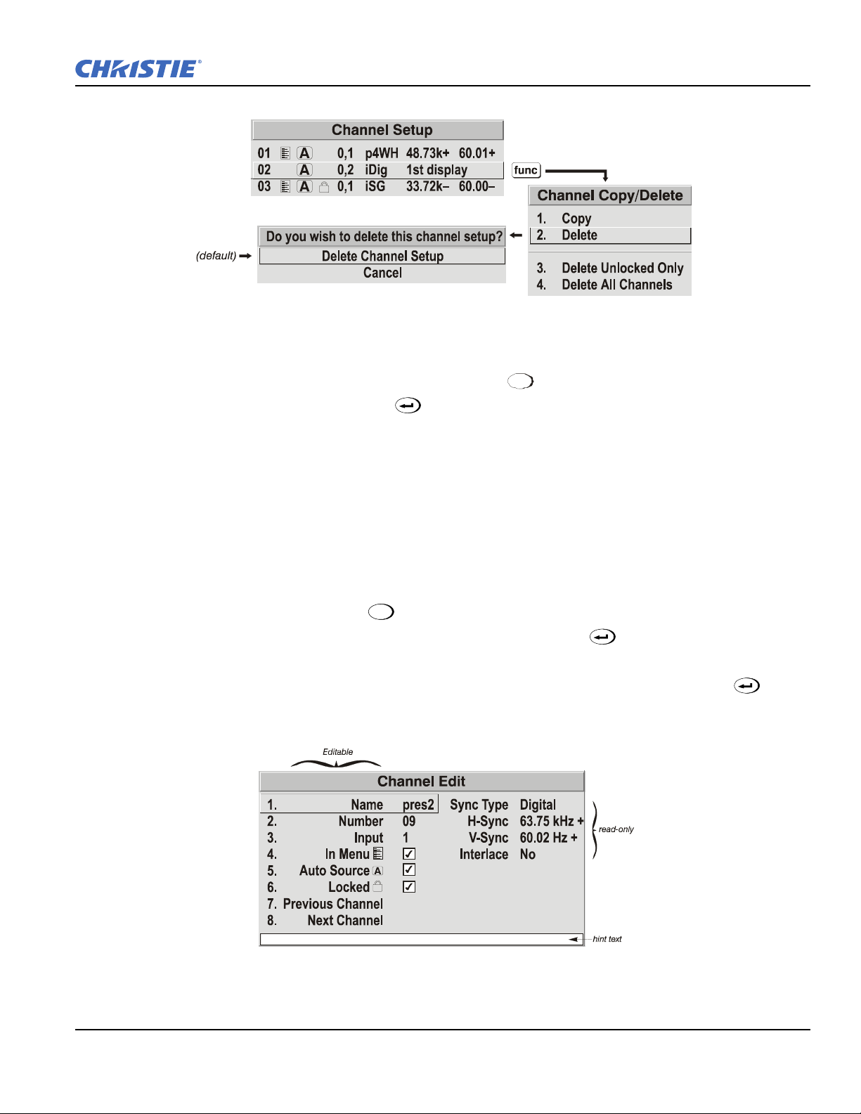
Section 3: Operation
Fu n c
Menu
Figure 3-15 Deleting a Channel
To D e l e t e M u l t iple Channels
Highlight the channel in the Channel Setup menu, and press to go to the Channel Copy/Delete submenu.
Select "Delete Unlocked Only" and press to delete all unlocked channels.
Or select "Delete All Channels" to delete all channels, even those that are locked. In either case, the current
channel will remain, but will be redefined from projector defaults.
NOTE:
For any deletion, a confirmation box appears to ensure that you really want to delete the channel(s).
Select "Cancel" (default) if you don't want to delete after all.
3.4.5 Editing a Channel Setup
The basic setups that describe how and where a channel can be accessed are listed in the Channel Setup menu.
These channel setups can be edited at any time in the Channel Edit submenu.
1. From the presentation level, press to display the Main menu. To display the Channel Setup menu,
press 3, or move the highlight to the Channel Setup option and press . The Channel Setup menu
will appear.
2. To edit parameters shown in the Channel Setup menu, select the relevant channel, and press . The
Channel Edit menu appears as shown in the sample in Figure 3-16.
Figure 3-16 Channel Edit Menu (SAMPLE)
Roadster, Matrix WU, Mirage S+/HD/WU User Manual 3-23
020-100002-06 Rev. 1(04-2011)
Page 76

Section 3: Operation
Menu
Menu
Exit
3. If desired, review and/or edit the selected channel’s setup options in the Channel Edit menu:
Channel Option Description Notes
Name An alpha-numeric label assigned to the current channel
which can be defined and/or changed as desired. Channel names can be upto 12 characters in length.
Number A 2-
DIGIT CHANNEL NUMBER.
IF YOU ENTER A CHANNEL NUMBER THAT
ALREADY EXISTS, A DIALOG MESSAGE
APPEARS INDICATING THAT THIS NUMBER IS
ALREADY IN USE. ASSIGN A DIFFERENT CHAN-
NEL NUMBER.
OU CAN DEFINE UP TO 99 CHANNELS.
Y
NOTES: 1) IF YOU ENTER A CHANNEL NUMBER THAT
ALREADY EXISTS, A DIALOG MESSAGE APPEARS INDI-
CATING THAT THIS NUMBER IS ALREADY IN USE-ASSIGN
A DIFFERENT CHANNEL NUMBER. 2) YOU CAN DEFINE
50
CHANNELS.
Input ENTER A NUMERIC VALUE (1 TO 8) CORRESPONDING TO
WHERE ON THE PROJECTOR'S INPUT PANEL THE SOURCE
IS CONNECTED.
In Menu I
F CHECKED (DEFAULT, EXCEPT FOR AUTOMATICALLY
DEFINED CHANNELS WITH UNCHANGED PARAMETERS),
THIS DEFINED CHANNEL THEN APPEARS IN THE LIST
AVAILABLE WHEN THE CHAN KEY IS PRESSED. IF
UNCHECKED, THE CHANNEL MUST BE ACCESSED VIA THE
NOTE: ON-SCREEN DISPLAY (OSD) OF THE CHANNEL
LIST IS AN OPTION THAT MUST BE SET IN THE MENU
REFERENCES MENU.
P
Channel Setup MENU (MENU + 3) ON THE KEYPAD OR
VIA THE AUTO SOURCE FUNCTION.
Auto Source IF CHECKED, (DEFAULT), THE PROJECTOR CAN AUTO-
MATICALLY LOCATE THIS CHANNEL WHEN AN INCOMING
INPUT SIGNAL MATCHES. IF NOT CHECKED, THE PROJEC-
TOR CAN LOCATE THE SELECTED CHANNEL ONLY WHEN
IT IS DIRECTLY SELECTED VIA THE CHAN KEY ON THE
KEYPAD.
Locked If checked, all of the image settings for this channel are
disabled (locked). If unchecked (default), all available
image settings can be adjusted as desired.
A
CHANGE IN INPUT SIGNAL WILL NOT RESULT
IN A CHANNEL CHANGE.
You cannot use Auto Setup with a locked
channel.
Previous
Channel
Select this option to see or change its C
tings for the previous channel in the Channel Setup list.
Next Channel Select this option to see or change its C
HANNEL EDIT set-
HANNEL EDIT set-
tings for the next channel in the Channel Setup list.
3.5 Adjusting the Image
The most commonly used options for image adjustments are accessed through the following two Main menus:
• Size and Position ( + 1)
• Image Settings ( + 2)
From either of these two menus, you can change settings affecting the image from the current channel by
working with the appropriate slidebars, check boxes, and drop-down lists.
Pressing returns you to the previous menu (or to the presentation, if from the Main menu), and accept
any changes you may have entered. Settings are saved for the current channel.
3-24 Roadster, Matrix WU, Mirage S+/HD/WU User Manual
020-100002-06 Rev. 1 (04-2011)
Page 77
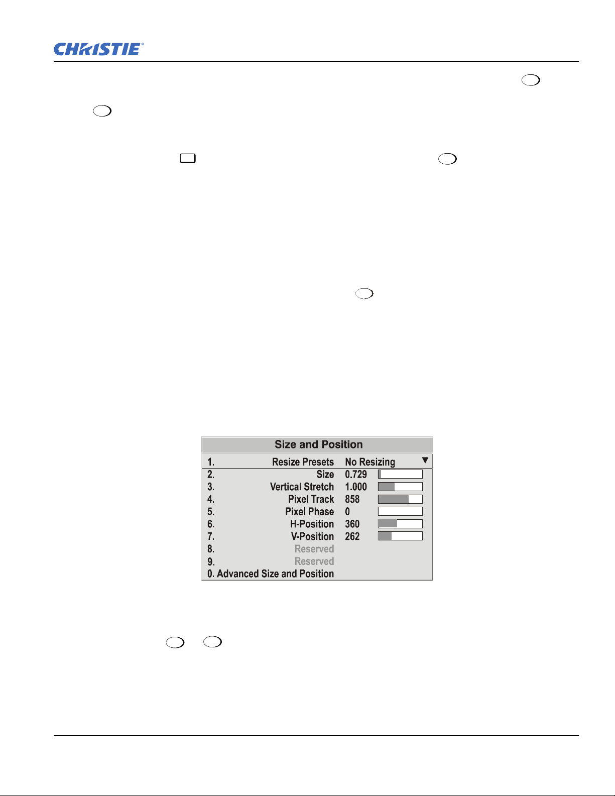
Section 3: Operation
Menu
Menu
Cont
Exit
Auto
Figure 3-17 Size and Position Menu
Exit
Menu
From your presentation, you can access any of the individual options in these menus by pressing ,
followed by the appropriate 2-digit number representing their location in the Menu system. For example, press
+ 2 + 3 to quickly access the "Gamma" option in the Image Settings menu.
Note that for certain options, you may prefer to use a "direct key" from presentation level to go directly to a
particular option without traveling through the menu system (available for certain display parameters only).
For example, press to access the "Contrast" slidebar immediately. Press to return to your
presentation.
NOTES: 1)
To hide these "direct" slidebars, disable the" Display Slidebars" check box in the Menu
Preferences menu. 2) To hide the entire Menu system from view, turn OFF the on-screen display by pressing
the OSD key.
3.5.1 Before You Begin
Using Auto Setup
For a most efficient first step in perfecting the image, press . This initiates an automated process in which
the projector quickly optimizes critical display parameters such as size, position, pixel tracking, etc., based on
the type of incoming source data detected. An Auto Setup can save considerable setup time, and you can still
modify the display parameter settings as desired using the menu options described below.
3.5.2 Size and Position Menu
In the Size and Position menu you can increase or decrease the size of your image, change its proportion
(aspect ratio), move the image to a specific area of the screen, and refine other related parameters. Use Size and
Position controls to match the image precisely to the screen used at the site.
Setu p
Refer to Section 3.3.5 Using Slidebars and Other Commands if you need help using any of the options and
controls. Changes made in the Size and Position menu are applied immediately, and are saved when you exit
the menu (press or ).
Resize Presets Option
NOTE: The same resize presets are available to all HD widescreen models. Please note however, the graphics
used to describe each preset in this section are of the SXGA+ models only.
Roadster, Matrix WU, Mirage S+/HD/WU User Manual 3-25
020-100002-06 Rev. 1(04-2011)
Page 78

Section 3: Operation
Figure 3-18 Resize Presets
Select a Resize Presets option to quickly display an image in its native resolution or to automatically resize an
image to closely fill the projector's native resolution of 1400 x 1050, or to optimize the width or height of your
display. Size, Position and Blanking parameters will automatically adjust accordingly. Or, if Blanking is set
first, which defines an Active Input Area. Resize Preset scaling will occur in this region of interest only.
Resizing options are explained in detail below.
What is the Resizing Default?
By default when displaying a new source, your image will utilize as much of the projector's display area (1400
x 1050) as possible for the type of incoming source data. Refer to Select Default below.
When “Custom” Appears
The Custom re-size descriptor automatically appears in the Size and Position menu when any of the values
for Size, Vertical Stretch, H-Position, V-Position or Blanking do not correspond to those for a preset. This
option is not a choice in the Resize Presets drop-down list.
Select Default
Select Default for most sources (factory default). The image is centered and displays as large as possible
(without affecting aspect ratio), depending on the type of input source, as described below:
• "A 5:4 graphic image will enlarge to fill the screen height, and be centered between narrow black sidebars.
• "A video image or 4:3 graphic image will enlarge to fill the screen width.
• "An HDTV (16:9) image will fill the width and be centered between black bars on top and bottom.
NOTE: Images and resolutions are shown for example only.
No Resizing
Select No Resizing to display the image in its native resolution, which is probably smaller than the projector's
1400 x 1050 resolution. For example, for a source with a native resolution of 800 x 600, the "No Resizing"
centers a small image within a black border. The black border areas are unused areas. See below.
3-26 Roadster, Matrix WU, Mirage S+/HD/WU User Manual
020-100002-06 Rev. 1 (04-2011)
Page 79

Section 3: Operation
Full Screen
Select Full Size to use all pixels (1400 x 1050) for displaying the image, regardless of source or original aspect
ratio. Incoming source material having a different aspect ratio than the projector will be stretched for display.
Full Width
Select Full Width to fill the projector's display from left-to-right without changing the original aspect ratio of
the image. Depending on the source, data at the top and bottom may be discarded (cropped), or the display may
have black borders at the top and bottom (called “letterboxed”)
Full Height
Select Full Height to fill the display from top-to-bottom. Depending on the source, this may create borders.
Anamorphic Option
Select Anamorphic to display an image in its native 16:9 aspect ratio without the use of an anamorphic lens
mount. The image fills the screen from top-to-bottom, and be centered between narrow black bars on each
side. This is used for DVD players that output widescreen images compressed into 4:3 NTSC format.
Roadster, Matrix WU, Mirage S+/HD/WU User Manual 3-27
020-100002-06 Rev. 1(04-2011)
Page 80

Section 3: Operation
Size
Size controls both the image width and height in tandem, maintaining the current aspect ratio (proportion) of
the displayed signal data.
Vertical Stretch
Vertical stretch adjusts the height of the image while keeping the width constant. Use Ve rtical St re t c h to change
the aspect ratio of the display.
Pixel Track
Steady flickering or several soft vertical stripes or bands across the entire image indicates poor pixel tracking.
Proper pixel tracking helps ensure that the image quality is consistent across the screen, that aspect ratio is
maintained, and that pixel phase can be optimized (described below). Tracking determines the frequency of the
pixel-sampling clock, indicated by the number of incoming pixels per line, so that all pixels generated by a
particular source are sampled.
NOTE: By default, the projector samples at the correct frequency for most sources.
For best results, use a good test pattern such as a smooth gray consisting of a clear pattern of black and white
pixels, or a similar "half ON, half OFF" graphic image, such as the Windows 2000 shutdown screen. Adjust
the slidebar until the vertical stripes broaden to the point where 1 large stripe fills the image. If the image still
exhibits some shimmer or noise, adjust the Pixel Phase (described below).
Pixel Phase
NOTE:
Adjust Pixel Phase after Pixel Tracking.
Adjust pixel phase when the image (usually from an RGB source) still shows shimmer or "noise" after pixel
tracking is optimized. Pixel phase adjusts the phase of the pixel-sampling clock relative to the incoming signal.
For best results, use a good test pattern such as a smooth gray consisting of a clear pattern of black and white
pixels, or a similar "half on, half off" graphic image, such as the Windows shutdown screen. Adjust the slidebar
until the image stabilizes and each pixel is clearly defined. You may notice that you can stabilize the image at
more than 1 point. For example, you may find that the image appearance at "11" is identical to the image
appearance at "38", thus you can use either setting.
If some shimmer from a video or HDTV source persists, use the "Filter" control to remove high-frequency
noise from the signal.
H-Position
Select the
H-Position option from the Size and Position menu. This option moves the image right or left
within the area of available pixels.
3-28 Roadster, Matrix WU, Mirage S+/HD/WU User Manual
020-100002-06 Rev. 1 (04-2011)
Page 81

Section 3: Operation
1.
2.
3.
4.
5.
Active Input Window
Top Blank
Bottom Blank
Left Blank
Right Blank
Plug & Display <EDID>
720x483
0
0
0
0
Advanced Size & Position
Native Resolution 60Hz
Figure 3-20 Blanking of a Primary Image
2048
2048
1080
1080
Image
Example: incoming image
Example: With Blanking
Blanking
(unused pixels)
NOTE: The value shown represents where the approximate center of the image lies in relation to the total
number of pixels available horizontally. This varies widely according to the signal-watch the image
while adjusting.
V-Position
Select the
V-Position option from the Size and Position menu. This option moves the image UP or DOWN
within the area of available pixels.
NOTE:
The value shown represents where the approximate center of the image lies in relation to the total
number of pixels available vertically. This varies widely according to the signal, watch the image
while adjusting.
Advanced Size and Position Submenu
This submenu consists of the following options:
Figure 3-19 Advanced Size and Position Submenu
Active Input Window
This read-only parameter indicates the current size (i.e., area) of your displayed data or "region of interest" as
defined by the blanking controls. For example, if you have blanked (cropped) 100 pixels from both the left and
right edges of an incoming source of 2048 x 1080, the remaining active input window is 1848 x 1080. When
using a video source at
INPUT 3 or INPUT 4, the default blanking of "0" defines an active input window of 720
x 483 for NTSC video.
Blanking (Top, Bottom, Left, and Right)
Crop the image as desired so that unwanted edges are
removed from the display (changed to black as shown in
Figure 3-20). Blanking defines the size of the Active Input
window, creating an area of interest. Range of adjustment
depends on the source resolution and other factors for your
application.
NOTE:
Blanking a PIP image resembles zoom (refer to
Figure 3-21). For example, left Blanking zooms the
right side of the PIP image; Right Blanking zooms
the left side. There are no black bars.
Roadster, Matrix WU, Mirage S+/HD/WU User Manual 3-29
020-100002-06 Rev. 1(04-2011)
Page 82
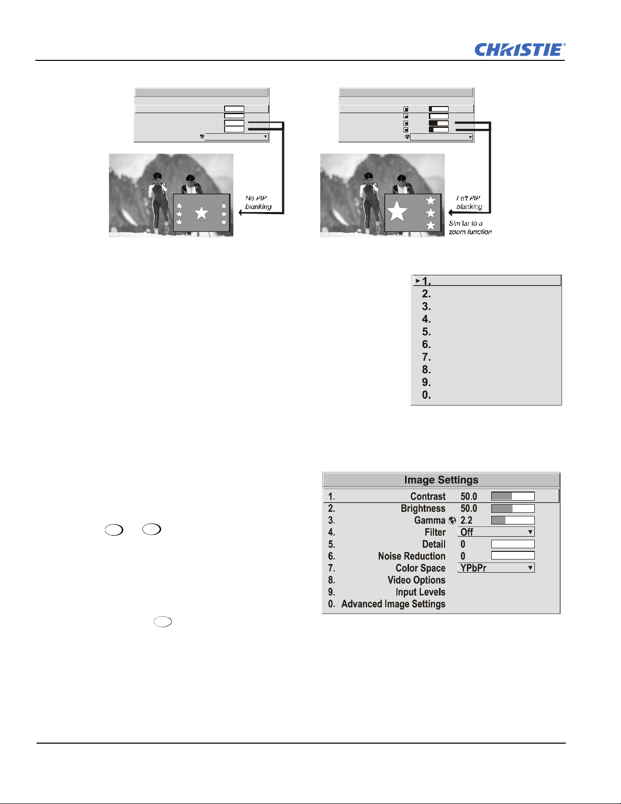
Section 3: Operation
1.
2.
3.
4.
5.
Top Blank
Bottom Blank
Le ft Bla nk
Right Blank
Plug & Disp lay <EDID>
PI P Advan ced Size & Posi tion
1600x1200
0
0
0
0
N ati ve R eso lut i on 60H z
1.
2.
3.
4.
5.
Top Blank
Bottom Blank
Left Blank
Right Bla nk
Plug & Display <EDID>
49
2
485
67
Figure 3-21 Blanking of a PIP Image
Native Resolution 60 Hz
1400x1050 60Hz
720p (1280x720 60Hz)
DC2K (2048x720 60Hz)
1024x768x116Hz 3D
1280x1024x110Hz 3D
1400x1050x102Hz 3D
1080p 60Hz / 1080i 60Hz
1080p 50Hz / 1080i 50Hz
1080p 24Hz / 1080i 30Hz
Figure 3-22 Image Settings Menu
Exit
Menu
Cont ra s t
Active Input Window
PIP Advanced Size & Position
Active Input W in dow
Plug & Display (EDID) Option
Select the Plug & Play option from the Advanced Size and Position
menu. By default, a Plug & Play (EDID) source outputs a signal
according to the EDID information provided by the projector. To override
this information and display in a different format (for example, if your
Plug & Play [EDID] device does not support the projector's resolution
and/or frequency), select the desired Plug & Play (EDID) resolution
from the list.
1600x1200
Native Resolution 60Hz
Any daisy-chained projectors also displays according to the chosen Plug
& Play (EDID) format.
EDID = Extended Display Identification Data standard.
3.5.3 Image Settings Menu
Use options in the Image Settings menu to alter your
image without affecting its size or position. Changes
made to the Image Settings menu are applied
immediately and are saved when you exit the menu
(press or ). Options not available for the
projector model or source are disabled and appear
dim (gray).
Contrast
Short Cut: Press and adjust the Contrast
slidebar.
"Contrast" increases or decreases the perceived difference between light and dark areas of your image (0-100).
For best results, keep close to 50. If the contrast is set too high, the light parts of the image lose detail and
3-30 Roadster, Matrix WU, Mirage S+/HD/WU User Manual
clarity. If the contrast set too low, the light areas will not be as bright as they could be, and the overall image
will be dim. For best results, start with a low value and increase so that whites remain bright , but are not
distorted or tinted, and that light areas do not become white (i.e., are "crushed").
020-100002-06 Rev. 1 (04-2011)
Page 83

Section 3: Operation
Brig ht
Off
RGB
HDTV
EDTV
SDTV
1.
2.
3.
4.
5.
NOTE: If the environment lighting changes, an adjustment of Gamma is recommended (see below).
Brightness
Short Cut: Press on the standard IR remote and adjust the Brightness slidebar in the menu.
Select Brightness from the Image Settings menu. "Brightness" increases or decreases the amount of black in
the image (0-100). For best results, keep close to 50. Start with a high value and decrease so that dark areas do
not become black (i.e., are "crushed"). Conversely, high brightness changes black to dark gray, causing
washed-out images.
NOTE:
Brightness should be adjusted before contrast, as Brightness setting affects the contrast setting.
Gamma
Gamma
Short Cut: Press on the standard IR remote and adjust the
Gamma slidebar in the menu.
Select Gamma from the Image Settings menu. "Gamma" is a
global setting that determines what gray shades are displayed
between minimum input (black) and maximum input (white) for all
signals. A good gamma setting helps to optimize blacks and whites
while ensuring smooth transitions for the "in-between" values
utilized in other colors.
Thus, unlike brightness and contrast settings controls, the overall tone of your images can be lightened or
darkened without changing the extremes, and all images display more vibrantly while still showing good detail
in dark areas.
Gamma fine-tunes the gamma table currently in use, ranging from 1- 3 (default = 2.2, indicating that the
chosen gamma table has not been adjusted). If excess ambient light washes out the image and it becomes
difficult or impossible to see details in dark areas, lower the gamma setting to compensate. This improves
contrast while maintaining good details for blacks.
Conversely, if the image is unnatural with excessive detail in black areas, increase the setting. For more
information, refer to the Advanced Image Settings submenu; Gamma Table. Again, look for good contrast
and good details in very dark areas.
Filter
The proper Filter setting is automatically set for virtually all signals, and rarely needs to
be changed. It applies a low pass filter for noise reduction in the incoming input signal,
particularly for HDTV or SDTV. Applied in the analog domain before sampling, this
filtering removes high frequencies and thus reduces pixel phase noise (note this also
reduces signal bandwidth). Override only if standard pixel tracking and phase adjustments
do not adequately clear up a "noisy" video signal, or if a graphics signal appears overly
"soft". Both instances indicate that "Filter" may be set to the wrong option.
Detail
"Detail" adjusts the sharpness of a video image so that edges remain clearly defined. It can be particularly
useful if a significant "Noise Reduction" adjustment has caused the image to appear too soft. Adjust until the
display is as sharp as desired, keeping in mind that because "Detail" adds some high frequencies back into the
image, it can also re-introduce a certain degree of noise.
Roadster, Matrix WU, Mirage S+/HD/WU User Manual 3-31
020-100002-06 Rev. 1(04-2011)
Page 84

Section 3: Operation
1.
2.
3.
4.
5.
6.
50.0
50.0
Enable Deco der AGC
Video Standard
Input Video Black
Col or
Tint
Decoder Luma Delay
Video Options
Auto
Noise Reduction
“Noise Reduction” is similar to the "Filter" control, but operates in the post-sampling digital domain with a
more subtle effect. Higher settings are most useful for clearing up noisy RGB images such as those from a PC.
Adjust as desired, keeping in mind that reducing noise (which reduces high frequencies) may also soften the
image.
Color Space
"Color Space" determines how the color components of an analog input signal or
certain digital signals connected to
decoded for accurate color in the display. Although color space for these analog signals
is automatically determined by the projector, in some circumstances you may wish to
override this and manually set a specific color space.
INPUT 1, INPUT 2, INPUT 5, or INPUT 6 are
NOTE: For most digital signals or for signals connected to
INPUT 3 or INPUT 4, the color space function is
entirely automatic and the drop-down list disabled.
The current color space appears in the Image Settings menu. Press to select a different option:
• Select
• Select
• Select
RGB unless you are using component video at INPUT 1, 2, 5, or 6.
YPBPR (Video) with a standard definition televised signal (SDTV)
YPBPR (HDTV) with a high definition televised signal (HDTV).
NOTE: When certain RGB signals are first connected, the projector may not initially recognize them as RGB
and incorrectly decodes their color information as YPbPr (video). These signals can include:
• RGB signals in NTSC, PAL, SECAM frequency ranges
• Scan-doubled sync-on-green
• Scan-quadrupled sync-on-green
For these signals, change the Color Space to RGB, then define a new channel for future use.
Video Options Submenu
This submenu is used with video sources only
(INPUTS 3 or 4).
0 IR E
35
3-32 Roadster, Matrix WU, Mirage S+/HD/WU User Manual
Enable Decoder AGC Option
Automatic Gain Control (AGC) affects decoded video images only. Enter a check mark (default) in most
instances to activate the decoder's AGC circuit and ensure properly bright images. Delete the check mark if a
decoded video image exhibits strange color artifacts such as stripes in highly saturated colors, indicating an
incompatibility between this source and the AGC.
020-100002-06 Rev. 1 (04-2011)
Page 85
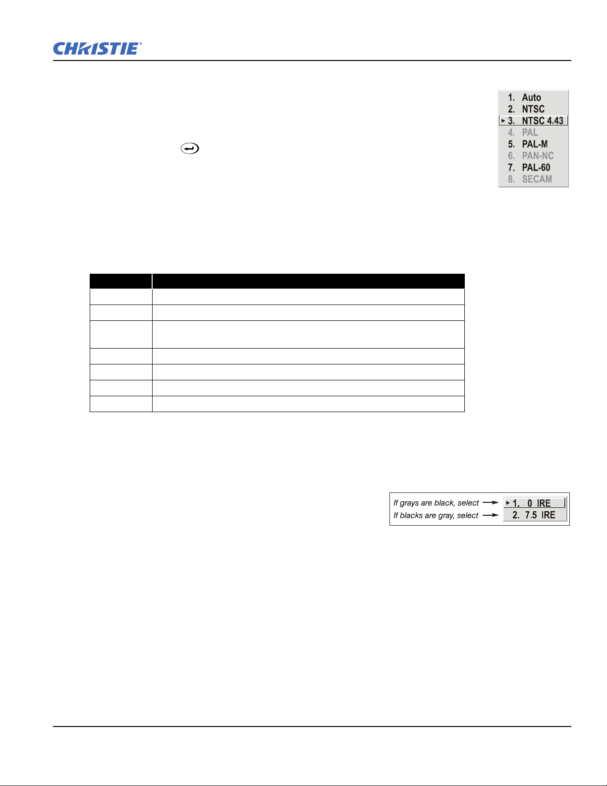
Section 3: Operation
Video Standard Option
For all but the more unusual video standards available in the world, the projector
automatically detects the incoming horizontal and vertical frequencies and sets the
projector's processing of this signal to the corresponding standard. The current video
standard name appears in the Video Options submenu, and includes an "A" if it has been
auto-detected. Press to view or select a different video standard from those available to
the projector-any that are disabled have frequency characteristics that differ from those of
the incoming signal. Selecting a specific standard forces the projector to process the signal
according to this standard.
NOTE: Best results are obtained with defined channels. Otherwise, switching from one video source to
another can sometimes cause slight disturbances in the display, indicating that the Auto function is
struggling. Recover by briefly selecting a different video standard, then going back.
Table 3.5 Regions and Video Standards: Summary
Standard Where Used (SUBJECT-TO-CHANGE)
NTSC
NTSC 4.43
PAL
PAL-M
PAL-NC
PAL 60
SECAM
N. AMERICA AND JAPAN
A TAPE-ONLY STANDARD FOR PARTIALLY-TRANSLATED HYBRID SIGNALS
MOST OF EUROPE, CHINA, AUSTRALIA, SOME OF S. AMERICA, SOME OF
A
FRICA
BRAZIL
ARGENTINA, CHILE, OTHER LATIN AMERICAN COUNTRIES
MOST OF EUROPE
FRANCE, EASTERN EUROPE, MOST OF AFRICA
NOTE:
Generally, use "Auto" for all instances EXCEPT: 1) a poor quality input signal or 2) a black-and-
white video signal. In order to detect and display such signals, select the relevant standard from the
list.
Input Video Black
This control compensates for incoming elevated black levels
present in certain video signals, and ensures that blacks in the
display are neither crushed (i.e., where dark grays appear black)
nor excessively elevated (i.e., where blacks appear dark gray).
By default, the projector automatically determines the best setting according to the type of incoming video
signal:
•
0 IRE - Used for DVD output with "enhanced black", SECAM, most PAL standards, and Japanese NTSC.
•
7.5 IRE - Used for most NTSC video signals.
For some types of video, you can override the setting. The control is disabled for other types of video (and all
graphics sources). Generally, if black appears crushed when brightness = 50, choose "0 IRE". If black appears
excessively elevated, use "7.5 IRE".
Color
This slidebar adjusts the color saturation level, i.e. the amount of color in a video image. Lower settings
produce less saturated colors. For example, a setting of "0" produces a black and white image. If the color level
is too high, colors will be overpowering and unrealistic.
Roadster, Matrix WU, Mirage S+/HD/WU User Manual 3-33
020-100002-06 Rev. 1(04-2011)
Page 86

Section 3: Operation
Tint
This slidebar adjusts the red/green color hue for true color reproduction of video and HDTV signals connected
to Input 3 or 4. For best results, adjust the tint while displaying an external test pattern,otherwise, it is
recommended that tint remain at its default setting.
Decoder Luma Delay
This control affects any incoming composite or S-video signal, delaying the luma signal (intensity) in relation
to the chroma (color). In the image, increasing the luma delay moves luma (seen as a shadow where colors
overlap) to the right slightly, with colors remaining in place. Decreasing this delay moves the shadow slightly
to the left. If necessary for your current source, adjust so that no shadows occur with adjacent colors.
Input Levels Submenu
Select Input Levels from the Image Settings menu.
NOTES: 1) Because the projector automatically optimizes input levels for all , but the most unusual of
sources, it is recommended that only experienced users use the Input Levels submenusubmenu. 2)
Before beginning, check that overall Contrast and Brightness settings are near 50 and that color
temperature is properly set up on an internal grayscale test pattern. 3) There must be at least 6-12
consecutive white pixels present in the image for proper "Auto Input Level" function. Leave this
control OFF after use.
Good RGB or input levels (that is, the drives and blacklevels for each of the 3 colors, red, green and blue)
ensure that images from analog sources, other than decoded video, have maximum contrast without crushing
black or white. By default (and in an "Auto Setup"), the projector automatically determines the best input
levels by monitoring image content and adjusting the controls appropriately. It is not necessarty to make
further adjustments to obtain proper blacks or whites.
NOTE:
This automatic adjustment requires at least 6-12 consecutive white pixels in the image. Without these
pixels, input levels may produce skewed colors, particularly in non-video images.
However, for a very unusual source exhibiting 1 or more overly high blacklevels (typically caused by a noisy
source causing blacklevel spikes), an experienced user may prefer to use the Input Levels menu (shown
above). These adjustments, which together serve as a calibration process compensating for differences in
sources and cabling, enable an experienced user to perfect the source image input levels and eliminate the
"overshoot" and "undershoot".
NOTE:
1) Input levels apply for the current source only, but for any color temperature used. 2) Assuming that
color temperature has been set up based on the internal test patterns, you can then set up input levels
for a given source so that it matches the color temperature of the internal test patterns.
Auto Input Level
Temporarily enter a checkmark only if you are an experienced user and you have an unusual source that you
feel needs further color temperature and/or input level adjustment. This compensates for incoming out-ofrange drives (white) and blacklevels (black) that would cause "crushing" of light and dark colors in the image.
Once the 6 slidebar values stabilize, clear the check box, and exit. The Auto Input Level should be
automatically turned OFF (check box cleared) upon exit from the Input levels menu.
Blacklevels and Drives
To check your image and adjust these controls:
1. Make sure overall Contrast and Brightness are both set to near 50.
ONT = 50 (approx.)
• C
3-34 Roadster, Matrix WU, Mirage S+/HD/WU User Manual
020-100002-06 Rev. 1 (04-2011)
Page 87

• BRIGHT = 50 (approx.)
Section 3: Operation
NOTE:
Not required for "Auto" adjustment.
2. Check the color temperature setup using an internal grayscale test pattern, making sure to obtain a neutral
grayscale.
NOTE: Not required for "Auto" adjustment.
3. Confirm that you are using an analog source not connected to
INPUT 3 or INPUT 4, as input levels are not
applicable for digital sources or sources going through the decoder. A grayscale is recommended.
4. If the blacks and/or whites appear OK, input levels do not need adjustment. If black levels are too high
(and/or whites are too low, which is rare), you likely have a noisy source that is producing skewed input
levels. Continue with Step 5.
5. Temporarily enable "Auto" in the Input Levels submenu. Wait for all 6 values to stabilize. Alternatively,
do not use "Auto", but reduce blacklevels manually instead. Judge by eye and change 1 or more of the 6
levels as necessary to obtain proper blacks and whites. You may want to see only a certain color while
adjusting by using the "Auto Color Enable" option (described below).
6. Delete the "Auto" check mark and leave the Input Levels menu.
IMPORTANT!
Do not use Input Levels to adjust color temperature. This distorts the Contrast and Brightness
functions, as well as color temperature.
Auto Color Enable
When a check mark is present, selecting a specific blacklevel or drive to adjust automatically enables the
corresponding color in the display. Remove the check mark to see all colors, or to enable a different specific
color through the Color Enable Control.
Clamp Location
This option (formerly known as “sync tip clamping”) can brighten the image produced
from certain high-resolution high-frequency graphic sources. For almost all sources, the
projector automatically selects the best clamp location. Use the normal Back Porch
location if the image is either sufficiently bright or overly bright. Select Sync Tip if the
image appears unusually dim, if there are horizontal streaks across the image, or if there is significant color
drift. This moves the clamping pulse from the normal backporch location (which is likely too short) to the tip
of the horizontal sync pulse. Tri L eve l is typically recommended for an HDTV source, where the back porch is
also short.
Color Enable
Select which color or colors you want to see in the display, useful while working with color temperature white
levels or input levels.
Peak Detector
The Peak Detector is a fast method for defining individual input levels, and can improve the accuracy of input
levels set by the Auto Input level function. Enabling the Peak Detector activates a special operating mode for
detecting only pixels that are considered black or white; all other levels are displayed as a mid-level gray.
When used with a smooth grayscale pattern in which black and white are known to be at opposite edges of the
image, you can watch these isolated areas while adjusting individual blacklevels and input drives until both
black and white edges are just visible and distinguished from neighboring pixels. Images from this source then
displays correct blacks and whites without crushing or washing out.
Roadster, Matrix WU, Mirage S+/HD/WU User Manual 3-35
020-100002-06 Rev. 1(04-2011)
Page 88
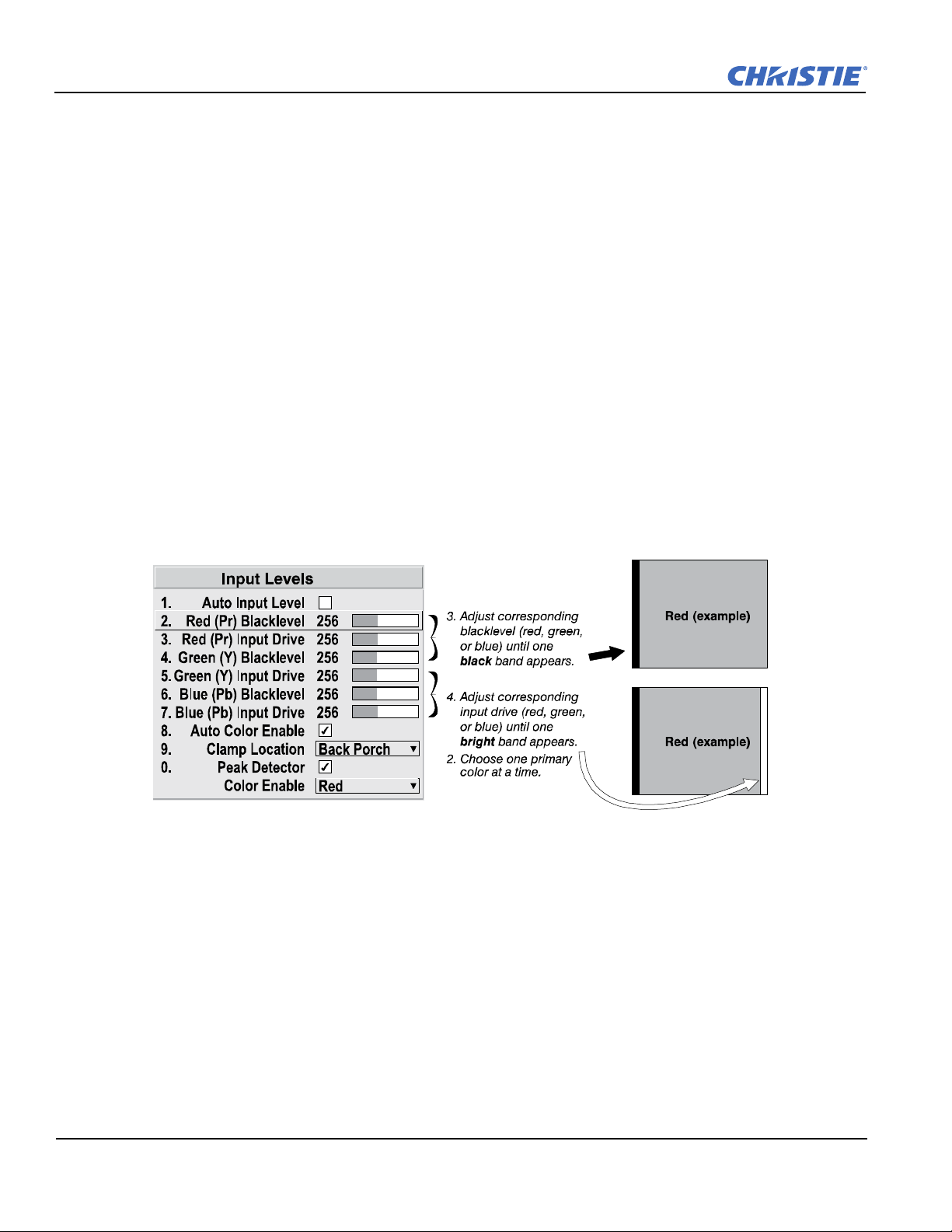
Section 3: Operation
Figure 3-23 Adjusting Input Levels Using the Peak Detector (RED EXAMPLE
SHOWN)
Refer to Figure 3-23Adjusting Input Levels Using the Peak Detector (RED EXAMPLE SHOWN).
1. Display a 16-level grayscale test pattern from the desired external source, and select the Peak Detector
check box.
NOTE:
The "Peak Detector" initially renders the grayscale as a uniform gray field before adjustment.
2. Display 1 primary color.
NOTE: Selecting Auto Color Enable ensures the correct color is displayed for each setting.
3. For the current color, adjust its corresponding "Blacklevel" slidebar just until a single band of black
appears at one edge of the screen. This band represents the first band of the grayscale pattern, which should
be 100% black. Do not adjust too far.
4. With the same color still active, adjust its corresponding "Input Drive" slidebar just until a single band of
color appears at the opposite edge of the screen. This band represents the last band of the grayscale pattern,
which should be 100% white (or the current color, if a certain color is enabled). Do not adjust too far.
5. It may be advantageous to go back and check the black band. Adjust the blacklevel slidebar if necessary.
NOTE: Re-adjusting blacklevels at this point affects the gain; only re-adjust if absolutely necessary.
6. Repeat Steps 3-5 with the other 2 remaining primary colors. When each primary color shows one
optimized black band and white (or colored) band, the input levels for this source are correctly set. Upon
exiting the Input Levels menu, the Peak Detector check box is cleared.
Advanced Image Settings
Use the Advanced Image Settings submenu to adjust lesser-used options used for more specialized
applications.
NOTE: 3D Source option is available for Mirage HD.
Gamma Table
This control applies a default video, graphics or simple gamma table or "curve" to your images, controlling the
intensity of midlevel colors and producing maximum contrast, brightness and color performance.
3-36 Roadster, Matrix WU, Mirage S+/HD/WU User Manual
020-100002-06 Rev. 1 (04-2011)
Page 89

Section 3: Operation
As shown at right, the graphics curve is a simple power curve while
the video curve has a linear segment near black to compensate for
increased blacklevels typical of video signals. A simple gamma
curve is a value of 2.2 and is correct for most signal conditions.
Although the projector automatically applies either the graphics or
video curve according to what type of incoming signal is detected,
in some cases you may wish to override this default and use
graphics gamma for a video source or video gamma for a graphics
source.
Alternatively, if neither default is ideal, you may prefer to apply the simple (non-optimized) gamma curve or a
user-defined custom gamma curve that has been created externally, named, and downloaded to the projector
(requires separate PC-based Arbitrary Gamma and KoRE Librarian software applications). If any of these
special user curves have been installed, their names appear in the Gamma Table drop-down list.
Keep in mind that any Gamma Table choice sets the related Gamma value (shown in the Image Settings
menu) to a 2.2 default, where it can be fine-tuned as desired. Different values (1-3) here indicate that the
original gamma table has been adjusted with either the
Select Color Adjustment
Gamma slidebar or direct key.
In "Select Color Adjustment", choose an overall color performance for all images. The "Max Drives" factory
default simply drives all 3 colors at their maximum level so that they are fully on and cannot be changed. The
two other pre-defined color adjustment choices, SD Video and HD Video, apply a color gamut optimized for
video sources (standard or high-definition). Alternatively, you can specify a color temperature, which enables
the nearby Color Temperature slidebar and applies its current setting (default = 6500K).
If none of the pre-defined "Select Color Adjustment" options or color temperatures suit your application, select
1 of 4 color gamuts previously defined by a user (User 1, 2, 3, or 4). A "User" option applies a customized
color performance in which the user has precisely set the hue and intensity of each color component in the
Color Adjustment by X/Y or Color Saturation submenus, and is most often needed with multiple-projector
applications. Select the color adjustment producing the best color accuracy for your application and
installation.
To configure a "User" color adjustment (gamut), use either the Color Adjustment by X/Y or Color
Saturation submenu.
NOTES: 1) "Color Temperature" defaults to 6500K until changed. All 4 "User" options default to SD Video
unless the user has redefined them. 2) Factory-defined color primaries, which ensure consistent color
gamut from projector-to-projector, can be altered in the Service menu only. If you suspect alteration,
the factory settings can be recovered with selection of Reset to Factory Defaults? in the Service menu
(password-protected).
Color Temperature
Adjust to apply a specific color temperature to all displays. Color temperatures are expressed in degrees Kelvin
(3200-9300K), and utilize different combinations of the projector's original native color primaries to produce a
"coloration" or cast (reddish or bluish) in images-the lower the temperature, the more reddish the cast; the
higher the temperature, the more bluish the cast.
NOTE: The slidebar is only enabled if you have a source connected, and have selected "Color Temperature"
in the adjacent "Select Color Adjustment" drop-down list in the Advanced Image Settings Submenu.
Roadster, Matrix WU, Mirage S+/HD/WU User Manual 3-37
020-100002-06 Rev. 1(04-2011)
Page 90
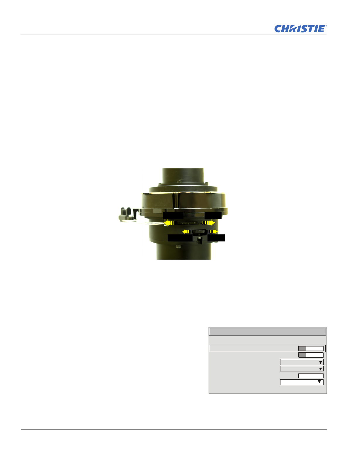
Section 3: Operation
Figure 3-24 Aperture Manual Adjustment
1.
2.
3.
4.
5.
6.
7.
Frame D elay Moni tor
Frame D elay
Dark Interval
3D Stero Sync Locking
3D Stero Sync Select
3D Stereo Sync Delay
Frame Lock Enable
Rese rved
Simulation 3D
1000
Lock ed
Figure 3-25 Mirage S+ Models
Optical Aperture
The optical aperture inside the projector controls the diameter of the light beam passing through the system.
With a fully open aperture (slidebar default of "0"), the maximum amount of light passes through for maximum
brightness in your images. Increase the slidebar setting to reduce the aperture diameter and maximize contrast
ratio instead. Performance of aperture depends on the lens in use.
NOTES: 1) Optical Aperture (when present) also appears in the Lamp menu.
Aperture Manual Adjustment
A variable position manual aperture is present on the 1.2:1 and 1.1:1 lens. It may be used together with the
internal electronic aperture to increase the contrast ratio; noting a slight decrease in brightness when it is used.
It is recommended for highest brightness operation, under normal conditions, the manual aperture is to be left
open. See Figure 3-24 below for aperture OPEN/CLOSE, and LOCK and UNLOCK dial positions.
NOTE: The lock/unlock dial position allows you to open the aperture at a desired position and lock it in
place.
CLOSE OPEN
UNLOCK LOCK
Reserved
No function.
Mirage S+ Series - Simulation 3D - Advanced Image Settings Submenu
From the Advanced Image Settings menu, use the
Simulation 3D submenu options to make timing adjustments
for realistic simulation environments.
NOTE: For complete 3D application notes, refer to the
separate Using 3D in Mirage manual provided with
the Mirage projector.
1047
1000
128
Output
Input A
3-38 Roadster, Matrix WU, Mirage S+/HD/WU User Manual
020-100002-06 Rev. 1 (04-2011)
Page 91

Section 3: Operation
Frame Delay Monitor
For best results, the bar width and value should remain fairly constant, indicating that timing of input and
output frames is locked; the Frame Delay Monitor value should stay within 5-10 lines or so of the Frame
Delay setting. If a frame is lost or "dropped", the slidebar moves suddenly and the values change, indicating
that the frame input is no longer equal to the output. If the signal is not locked, the values will change
erratically; you can adjust the Frame delay to attempt a correction.
NOTE: For more information, refer to separate Using 3D in Mirage manual provided.
Frame Delay
Set the number of lines delayed between the input signal and its appearance on screen, keeping in mind that
projector processing always adds 1 frame of delay to the frame delay setting. For applications such as
simulation, where the feeling of "real time" image response is a priority, a minimum setting is usually
preferable. For projectors capable of 3D (stereographic) applications where alternating left-right frames must
be synchronized with the corresponding L/R shutters in 3D glasses, a total frame delay setting of 2 (or multiple
of 2) may be more useful. If set too high or low, frame locking will not be possible-most sources require
approximately 50 lines of delay to ensure frame locking.
NOTE: For more information, refer to separate Using 3D in Mirage manual provided.
Dark Interval
Adjust the Dark Interval to artificially increase the amount of dark time between displayed frames for
stereographic 3D images. Higher settings provide more time for shutters in 3D glasses to open/close, ensuring
that each eye sees the full display intended for it. Symptoms of cross talk and/or color artifacts can indicate
need for adjustment. The Dark Interval range of adjustment depends on the vertical frequency of your sourcethe higher the frequency, the smaller the range.
NOTE: For more information, refer to separate Using 3D in Mirage manual provided.
3D Stereo Sync Locking
This option defines 1) whether or not the incoming stereographic 3D signal locks to the vertical sync output so
that signals are synchronized, and 2) whether or not the 3D frames must be inverted, i.e. swapped left-withright. The correct setting ensures that the projector's 3D display of left/right frames is synchronized with the
rest of the 3D system components so that the intended eye sees the left/right image data. Select the option
corresponding to your 3D source connections and timing, and use only if the Mirage 3D Stereo Sync Cable is
connected between the projector's GPIO port and a server. Keep this adjustment OFF (default) when you are
not using the Mirage 3D Stereo Sync Cable.
With your sync cable and, if desired, emitter connected as described in the Using 3D in Mirage manual, select
the option suited to your 3D configuration (see above). If Frame Delay is 2 (or 0), do not invert; if frame delay
is 1 or 3, invert. Generally, an "Unlocked" setting is synchronized with the incoming L/R signal rather than the
vertical sync output, and may be needed only with multi-projector installations in which the vertical sync
outputs vary.
Roadster, Matrix WU, Mirage S+/HD/WU User Manual 3-39
020-100002-06 Rev. 1(04-2011)
Page 92

Section 3: Operation
Locked
Rate Matched
n
1.
2.
1.
2.
3.
4.
5.
6.
7.
Frame Delay
Dark Interval
3D Sync Input
3D Sync Output
Frame Lock Enable
3D Source
Simulation 3D
592
Locked
Figure 3-26 Mirage HD/WU Models
NOTE: For more information, refer to the separate Using 3D in Mirage manual provided.
3D Stereo Sync Select
Define which of the Mirage 3D Stereo Sync Cable's input connecters is routed from your server. Use only if the
cable is present.
3D Stereo Sync Delay
Set when the L/R frames begin, defining the best reference point for synchronizing the display with your
glasses. Proper adjustment of this delay should eliminate cross talk and odd colors caused by timing
differences between the glasses and the projected display. Use this slidebar only if the Mirage 3D Stereo Sync
Cable is connected between the projector's GPIO port and a server. Slide bar values indicate the number of
lines that are delayed.
Frame Lock Enable
This option allows the projector to control the output frame timing based on the input
signal. The Locked option forces (if possible) the output image to be phase locked to the
input frames. Rate Matched means that the output runs at close to the input frequency ,
but is not locked to it so the output will drift in phase relative to the output. Free Run
forces the output to run at a 60Hz frame rate.
NOTE: For more information, refer to the separate Using 3D in Mirage manual provided.
Mirage HD/WU Series - Simulation 3D - Advanced Image Settings Submenu
From the Advanced Image Settings menu, use the
Simulation 3D submenu options to make timing
adjustments for realistic simulation environments.
Frame Delay Monitor
Frame Delay Monitor
This slidebar monitors the latency between input and
output. For best results, the bar width and value should
remain fairly constant, indicating that timing of input and
3D Stereo Sync Dela y
output frames is locked; the Frame Delay Monitor value
should stay within 5-10 lines or so of the Frame Delay
setting. If a frame is lost or "dropped", the slidebar moves
suddenly and the values change, indicating that the frame
input is no longer equal to the output.
NOTE: For more information, refer to separate the Using 3D in Mirage manual provided.
Free Ru
3.
1047
1000
2500
Input A
To Emitter
3-40 Roadster, Matrix WU, Mirage S+/HD/WU User Manual
020-100002-06 Rev. 1 (04-2011)
Page 93
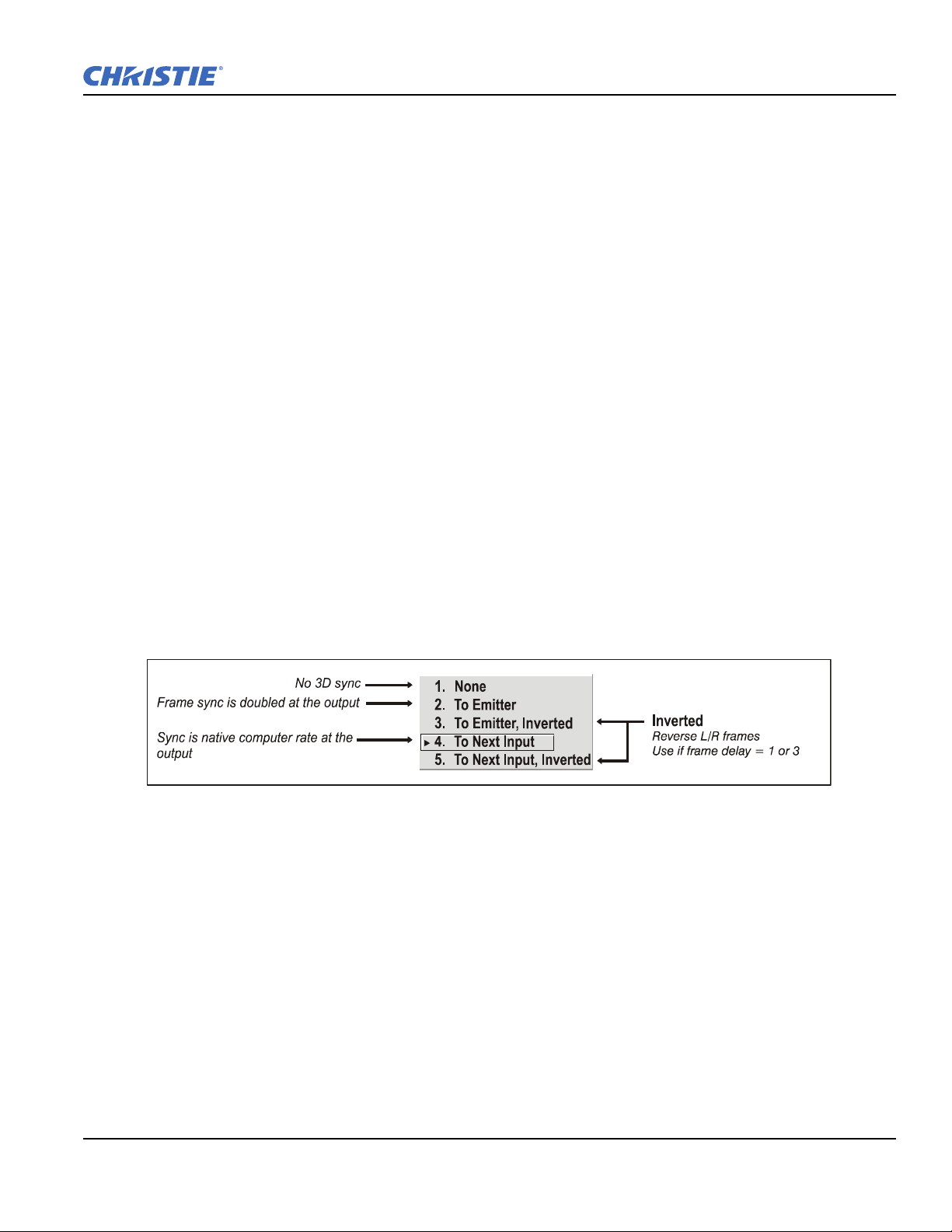
Section 3: Operation
Frame Delay
Set the number of lines delayed between the input signal and its appearance on screen, keeping in mind that
projector processing always adds 1 frame of delay to the frame delay setting. For applications such as
simulation, where the feeling of "real time" image response is a priority, a minimum setting is usually
preferable. For projectors capable of 3D (stereographic) applications where alternating left-right frames must
be synchronized with the corresponding L/R shutters in 3D glasses, a total frame delay setting of two (or
multiple of two) may be more useful. If set too high or low, frame locking will not be possible-most sources
require approximately 50 lines of delay to ensure frame locking.
Dark Interval
Adjust Dark Interval to artificially increase the amount of dark time between displayed frames for
stereographic 3D images. Higher settings provide more time for shutters in 3D glasses to open/close, ensuring
that each eye sees the full display intended for it. Symptoms of cross talk and/or color artifacts can indicate
need for adjustment. The Dark Interval range of adjustment depends on the vertical frequency of your sourcethe higher the frequency, the smaller the range.
NOTE: For more information, refer to separate the Using 3D in Mirage manual provided.
3D Stereo Sync Locking
This option defines 1) whether or not the incoming stereographic 3D signal locks to the vertical sync output so
that signals are synchronized, and 2) whether or not the 3D frames must be inverted, i.e. swapped left-withright. The correct setting ensures that the projector's 3D display of left/right frames is synchronized with the
rest of the 3D system components so that the intended eye sees the left/right image data. Select the option
corresponding to your 3D source connections and timing, and use only if the Mirage 3D Stereo Sync cable is
connected between the projector's GPIO port and a server. Keep this adjustment OFF (default) when you are
not using the Mirage 3D Stereo Sync cable.
With your sync cable and, if desired, emitter connected as described in the Using 3D in Mirage manual, select
the option suited to your 3D configuration (see above). If Frame Delay is 2 (or 0), do not invert; if frame delay
is 1 or 3, invert. Generally, an "Unlocked" setting is synchronized with the incoming L/R signal rather than the
vertical sync output, and may be needed only with multi-projector installations in which the vertical sync
outputs vary.
NOTE: For more information, refer to separate the Using 3D in Mirage manual provided.
3D Sync Input
Define which of the Mirage 3D Stereo Sync Cable's input connecters is routed from your server. Use only if
the cable is present. Only the first projector, possibly connected to external sync, will choose any of these
selections. Every other projector will be getting sync from the previous projector on
Roadster, Matrix WU, Mirage S+/HD/WU User Manual 3-41
020-100002-06 Rev. 1(04-2011)
INPUT A or INPUT B.
Page 94
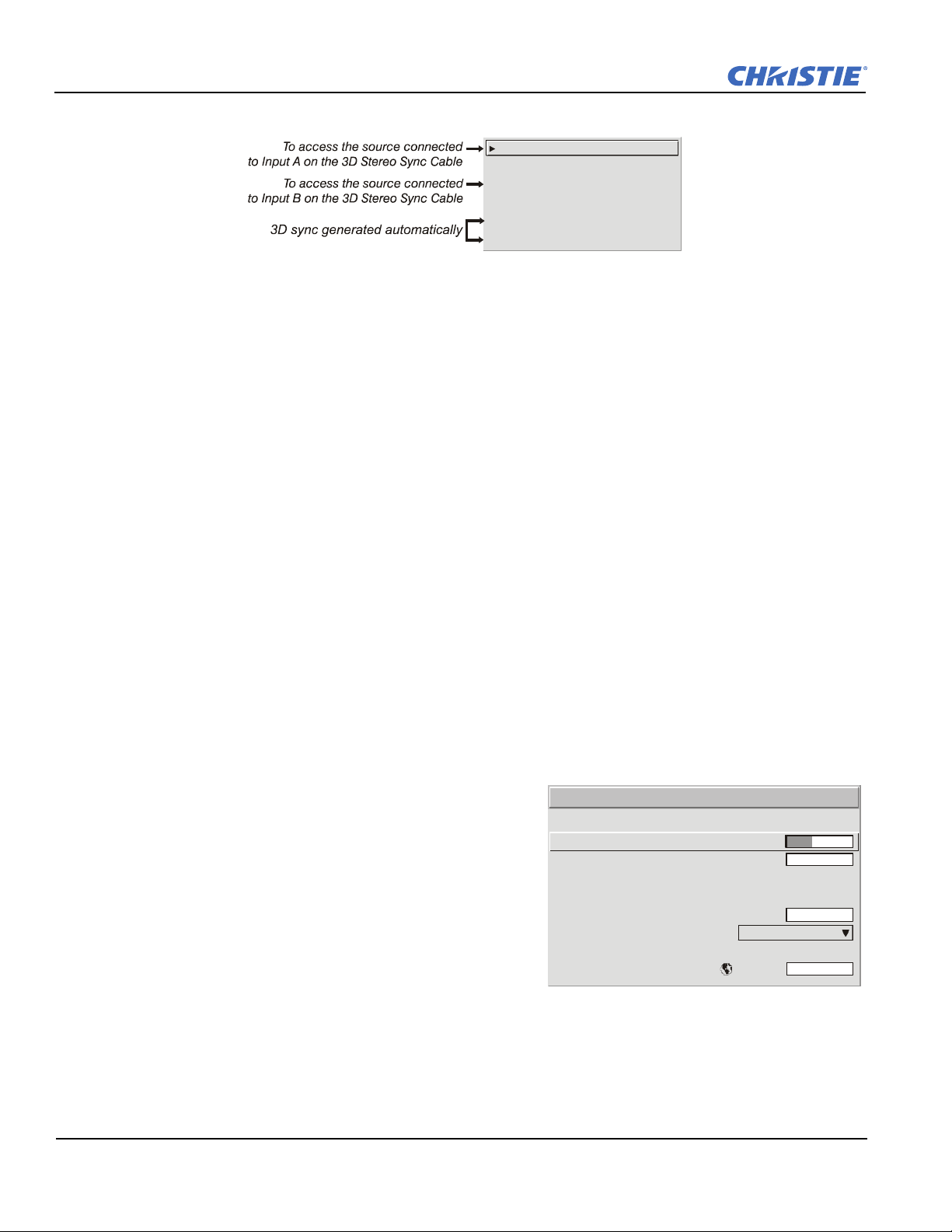
Section 3: Operation
Input A
Input A, inverted
Input B
Input B, inverted
None / internal
None / internal, inverted
1.
2.
3.
4.
5.
6.
1.
2.
6.
7.
8.
3.
4.
5.
Frame Delay Monitor
Frame Delay
Accufr ame
Fr ame L ock En able
Reserved
Warp Latency
Reserved
Reserved
Reserved
Simulation 3D
Locked
Figure 3-27 All Matrix Models
3D Stereo Sync Delay
This value is set when the L/R frames begin and by default, is automatically calculated based on signal timing;
it defines the best reference point for synchronizing the display with your glasses. Proper adjustment of this
delay should eliminate cross talk and odd colors caused by timing differences between the glasses and the
projected display. Slidebar values indicate the number of lines that are delayed.
NOTE: See Help menu to view the formula used to calculate this value.
Frame Lock Enable
This option allows the projector to control the output frame timing based on the input signal. The Locked
option forces (if possible) the output image to be phase locked to the input frames. Rate Matched means that
the output runs at close to the input frequency , but is not locked to it so the output will drift in phase relative to
the output. Free Run forces the output to run at a 60Hz frame rate.
NOTE: For more information, refer to the separate Using 3D in Mirage manual provided.
3D Source
When using a Mirage projector with HD resolution, a check box option called 3D Source will be added to the
bottom of the Simulation 3D menu. This check box must be set by the user for all new 3D sources, and cleared
for all new non-3D sources (default setting is checked). Once set, this value will be maintained for that source
for all future uses. This option is also available under the Advanced Image Settings menu.
Simulation 3D - Advanced Image Settings Submenu - MATRIX MODELS ONLY
NOTES: Available in Matrix projectors Only.
Use the options in the Simulation 3D menu to make the
timing adjustments necessary for realistic simulation and 3D
images.
Frame Delay Monitor
For best results, the value should remain fairly constant,
indicating that timing of input and output frames is locked;
the Frame Delay Monitor value should stay within 5-10 lines
or so of the Frame Delay setting. If a frame is lost or
"dropped", this value will cycle to maximum and jump to
minimum and then repeat, indicating that the frame input is
no longer equal to the output. If the signal is not locked, the
values will change erratically; you can adjust the Frame delay to attempt a correction.
3-42 Roadster, Matrix WU, Mirage S+/HD/WU User Manual
1050
1050
0
0
020-100002-06 Rev. 1 (04-2011)
Page 95

Section 3: Operation
Frame Delay
Set the number of lines delayed between the input signal and its appearance on screen, keeping in mind that
projector processing always adds 1 frame of delay to the frame delay setting. For applications such as
simulation, where the feeling of "real time" image response is a priority, a minimum setting is usually
preferable. For projectors capable of 3D (stereographic) applications where alternating left-right frames must
be synchronized with the corresponding L/R shutters in 3D glasses, a total frame delay setting of 2 (or multiple
of 2) may be more useful. If set too high or low, frame locking will not be possible-most sources require
approximately 50 lines of delay to ensure frame locking.
AccuFrame
Increasing the AccuFrame value will reduce the artifacts related to fast motion in simulation content.
Symptoms of blurry objects or loss of apparent detail may indicate a need for this value to be adjusted.
NOTE: If increasing AccuFrame does not improve image quality, reduce the value to 0. Increasing
AccuFrame may increase 'flicker' of the display and may reduce overall brightness.
Frame Lock Enable
This option allows the projector to control the output frame timing based on the input signal. The Locked
option forces (if possible) the output image to be phase locked to the input frames. Rate Matched means that
the output runs at close to the input frequency , but is not locked to it so the output will drift in phase relative to
the output. Free Run forces the output to run at a 60Hz frame rate.
Reserved
No function.
Warp Latency
Requires optional Christie TWISTTM module. Refer to Christie TWISTTM User's Manual provided with the
module.
Advanced Image Settings Submenu
Motion Filter
This control is most useful for smoothing out moving images from interlaced sources. In most
cases the proper Motion Filter setting is automatically determined according to the type of
incoming source signal. However, if your source is noisy and/or inconsistent, you may wish to
"force" a setting to ensure stable processing for this source.
If desired, override the default "Auto" setting by selecting the appropriate motion filter:
Auto T
Still F
Motion F
HE PROJECTOR AUTOMATICALLY USES THE CORRECT MOTION FILTER ACCORDING TO THE
INCOMING SIGNAL.
OR STATIC IMAGES WITH NO MOTION, SUCH AS GRAPHICS FROM A CD.
OR VIDEO IMAGES THAT DID NOT ORIGINATE FROM FILM, OR FOR MOVING COMPUTER-GENER-
ATED IMAGES.
Film F
Roadster, Matrix WU, Mirage S+/HD/WU User Manual 3-43
020-100002-06 Rev. 1(04-2011)
OR VIDEO IMAGES THAT ORIGINATED FROM FILM. THIS WILL OPTIMIZE IMAGE QUALITY AND
STABILITY.
Page 96

Section 3: Operation
Image Orientation
Auto Power Up
Set Date And Time
Menu Preferences
Communications
Geometry and Color
Diagnostics and Calibration
Service
Option 1 Card: Dual SD/HD-SDI
Language
Reserved
Option Card 2 Empty
1.
2.
3.
4.
5.
6.
7.
8.
9.
0.
English
Front
Configuration
Film Mode Threshold
This setting determines how sensitively the projector can detect if an incoming video signal originated from
film or not.
Detail Threshold
Use "Detail Threshold" to define at what frequency level the "Detail" control will begin to magnify high
frequencies, which adds details back into the image. Raise the threshold to ignore more of these high
frequencies, and lower the threshold to magnify more of these frequencies. A setting of "0", for example,
means no noise is ignored and all is magnified. An ideal detail threshold is 1 in which high frequencies that are
causing objectionable noise are not magnified when using "Detail", but frequencies which can help sharpen an
overly-soft image are magnified.
3D Source
When using a Mirage projector with HD or WUXGA resolution, a check box option called 3D Source will be
added to the bottom of the Advanced Image Settings menu. This check box must be set by the user for all new
3D sources, and cleared for all new non-3D sources (default setting is checked). Once set, this value will be
maintained for that source for all future uses. This option is also available under the Simulation 3D menu in
Mirage HD or WUXGA projectors only.
Floating Inputs
This allows the signals connected to inputs 1, 3, and 4 to have floating ground references relative to the
projector. Floating the inputs can remove hum bars in the image if the installation has conflicting grounds.
However, floating the inputs can also introduce hum bars when the signal ground is the only connecting
ground. Select the setting that produces the best image.
3.6 Adjusting System Parameters and Advanced Controls
Use the Configuration menu to define general
operating parameters and communications with
other projectors and equipment, and to access other
advanced processing and image adjustments
affecting overall performance. In addition, the
Configuration menu provides access to
diagnostics, calibration tools and the Service
submenu (password-protected).
Keep in mind that settings in the Configuration
menu (and its submenus) are typically "global"
settings applied regardless of the type of source your
are using. This characteristic is identified with the
Globe icon alongside the option.
NOTE
: The Configuration menu is recommended for experienced users/technicians only.
3-44 Roadster, Matrix WU, Mirage S+/HD/WU User Manual
020-100002-06 Rev. 1 (04-2011)
Page 97

3.6.1 System Configuration (General Settings)
Chan
Input
The first 6 “General” options in the Configuration menu are explained below:
Language
Choose from available languages to use in the projector's menus. The change takes effect immediately.
Image Orientation
Set the orientation of the image according to the orientation of your projector. If the setting is incorrect,
projected images are reversed and/or upside down.
Reserved
No function.
Auto Power-up
Enter a check mark to enable the projector to automatically power up after losing power due to a power failure
or due to unplugging the projector during operation.
Section 3: Operation
NOTE:
Unsaved display adjustments may be lost.
Set Date & Time
Enter/read the current year-month-day and hour-minute-second. Changes here reset the projector's real-time
clock.
Menu Preferences
Adjust the appearance, content and/or location of on-screen menus and messages.
Large Menu Font
Enter a check mark to enlarge menus and their text. You may have to adjust "Menu Location" to accommodate
the increased menu area.
Menu Location
Use the drop-down list to choose a pre-defined default or customized location for the display of all on-screen
menus.
To create a custom menu location quickly, choose a preset that is closest to the desired location. Then adjust
the slidebars of Horizontal Shift and Vertical Shift to move the menu to the desired location. To prevent
cropping of larger menus, avoid locations too close to a corner or edge.
Horizontal and Vertical Shift
Shift your menus as desired, creating a customized menu location.
Display Channel List
Enter a check mark if you want to see a scrollable channel list whenever you press from your
presentation. Channels marked with a icon in the Channel Setup menu then appear in the list. The Display
Channel List option also enables on-screen feedback when using the key. If you prefer to hide the
channel list and input dialog box while switching channels and sources during a presentation, clear the check
box.
Roadster, Matrix WU, Mirage S+/HD/WU User Manual 3-45
020-100002-06 Rev. 1(04-2011)
Page 98

Section 3: Operation
Contrast
Bright
1.
2.
3.
4.
5.
6.
7.
8.
9.
0.
Baud Rate for RS232
Baud Rate for RS422
Projector
Network Routing
Ethernet Settings
Broadcast Key
Backlight
Front IR
Back IR
Wired Keypad
115200
19200
004
All Joined
Off
On
On
Communications
Figure 3-28 Communications
NOTE: The Channel list and Input dialog box cannot be hidden during use of the menus.
Display Slidebars
Enter a check mark to superimpose a small slidebar over the current image whenever an adjustable parameter
is selected directly with a key such as or . If "Display slidebars" is unchecked, these slidebars can
still be accessed, but will be hidden during adjustment. This option does not affect slidebars in menus.
Display Error Messages
Choose how you want to be notified of errors detected in either the incoming signal or projector. Select
"Screen" or "All" (default) to see brief on-screen messages. This is particularly recommended during setup or
testing of the projector. Or, select "Serial Ports" to receive messages via RS-232 or RS-422 serial communication only. To hide error message displays, such as during shows and presentations, select "OFF" or "Serial
Ports".
Splash Screen Setup
Use the Splash Screen to choose when you would like to display a special introductory splash screen image,
such as your company logo, graphic or message.
3.6.2 System Configuration (Communication)
3-46 Roadster, Matrix WU, Mirage S+/HD/WU User Manual
Always Off A
Always On A
Startup Only T
Startup and No Signal A
SPLASH SCREEN NEVER APPEARS.
SPLASH SCREEN IS ALWAYS ON BEHIND THE CURRENT DISPLAY IMAGE, SIMI-
LAR TO WALLPAPER.
HE SPLASH SCREEN LOGO APPEARS AT PROJECTOR STARTUP ONLY.
SPLASH SCREEN APPEARS AT STARTUP ONLY IF THERE IS NO SOURCE SIGNAL.
To replace the default "Christie logo" splash screen (or other) with one of your own, use the KoRE Librarian
to download the desired .bmp to the projector. This overwrites the current splash screen content in projector
memory.
Settings in the Communications submenu define and
control how single or multiple projectors are can link with
each other and with a controlling device. See Figure 3-28.
Baud Rates
The baud rate setting determines the speed of
communication to and from the projector on the RS-232
or RS-422 links. The maximum rate for either standard is
115200. Set the baud rate to match that of your
controlling device, such as your PC. If you are unsure
about what baud rate to choose, refer to the documentation for the controlling device. In an existing network of
projectors, if you discover that a projector has a different
baud rate, make sure to use the drop-down list and select the correct baud rate using the key. Do not just
scroll this control with the keys. Serial communication is always 8 data-bits, no parity.
020-100002-06 Rev. 1 (04-2011)
Page 99

Section 3: Operation
Proj
Exit
Projector
Enter a 3-digit number (such as "001") to assign or change a number to the projector currently in use. If the
current projector already has a number assigned, that number appears here (for example, "004" in , above).
Numerical identity for projectors enables you to communicate with a single projector within a multiple-
projector application (see also key in Section 3.2 Using the Keypads). If you make a mistake in assigning
or changing the projector number, press to cancel.
NOTE: When multiple projectors are being used and you want to adjust the color and edge blending settings
for individual projectors to create one seamless image, you must assign different numbers for each
projector to allow switching back and forth between projectors while adjustments are being made
Network Routing
NOTE: Not applicable for stand-alone projectors or simple networks with only 1 type of controller and
linking.
Separate. Select "Separate" (factory default) to keep RS-232, RS-422 and Ethernet messages on their
respective paths instead of being broadcast to the other types of ports. In Figure 3-29 A, RS-422 controls only
the projector to which it is connected. In Figure 3-29 B; either RS-232 or RS-422 will control the network.
Figure 3-29 Using the "Network Routing" Option
RS-232 and RS-422 Joined. Messages to and from any serial port is also relayed to all other serial ports. Use
when there is only 1 physical link between any 2 projectors, but which might be RS-232 or RS-422.
Roadster, Matrix WU, Mirage S+/HD/WU User Manual 3-47
020-100002-06 Rev. 1(04-2011)
Page 100
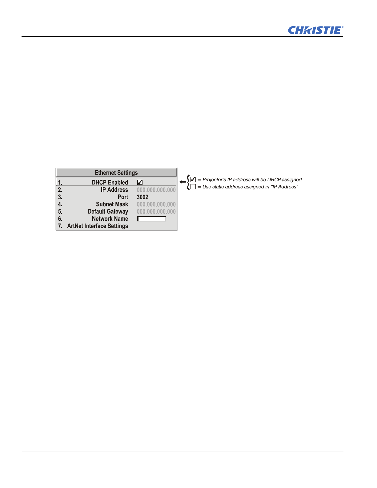
Section 3: Operation
RS-232 and Ethernet Joined. Messages to and from the RS-232 ports are also relayed to the Ethernet port,
and vice versa. Any RS-422 communications are isolated.
All Joined. All messages reach all ports, regardless of type.
Ethernet Settings Submenu
NOTES: Recommended for network administrators only.
DHCP
Select this check box if you want a DHCP server to automatically change the projector's default IP address
(0.0.0.0) to 1 that is valid and unique for use on the current Ethernet network.
On networks without a DHCP server, or to simply override the automatic DHCP server function, clear the
check box, and enter the new "IP Address" settings desired. Remember that only a 0.0.0.0 address triggers the
DHCP addressing service only when the DHCP check box is enabled.
IP Address
Enter a valid and unique IP address for use on the network to which the projector is currently connected. Upon
the next power-up, this address will overwrite any previous IP address such as the projector's factory-defined
default (0.0.0.0), or 1 that has been assigned by a DHCP server or other user. An IP address entered here
remains in effect until it is changed again.
NOTE:
Make sure the projector is connected to the network before changing its IP address. Make sure to re-
boot.
Port
On some Ethernet networks, firewall restrictions may require that the port number of the projector be changed
from its default of 3002. If so, enter a new valid port number here. . It is highly recommended not to use a port#
below 1024, as these ports are typically reserved by common IP applications.
Subnet Mask and Default Gateway
The Subnet Mask and Default Gateway are automatically assigned when DHCP is enabled. If a static IP is
being used, the IP must be assigned first since the subnet mask is estimated by the projector after the IP is
entered. The Default Gateway is an optional router device used to send and receive data outside the subnet.
ArtNet Interface Settings Submenu
ArtNet is an Ethernet communication protocol that was developed by Artistic Licence. It is used for controlling
lighting/staging equipment from a lighting console or PC application. It is based on the popular DMX512
control protocol.
ArtNet Subnet. This is the highest level address for a device. Typically it is set to 0.
3-48 Roadster, Matrix WU, Mirage S+/HD/WU User Manual
020-100002-06 Rev. 1 (04-2011)
 Loading...