

Page 1

USER
MANUAL
Page 2
TableofContents
1. INTRODUCTION
2. INSTALLATION &
SETUP
3. OPERATION
1.1 The Projector..............................................................2
1.2 Components...............................................................3
2.1 Setting Up Your Projector.............................................4
2.2 Screen And Projection Distance................................... 4
2.3 Power Connection.......................................................5
2.4 External Connection....................................................6
2.4.1 Connecting to a Personal Computer...................6
2.4.2 Connecting to a Video/ Laser Disk/ DVD Player... 8
2.4.3 Connecting to External Speakers.......................10
2.5 Mouse Functions.........................................................11
3.1 Projector Basics..........................................................12
3.2 Turning On & Turning Off The Projector......................... 15
3.3 Basic Operation..........................................................16
3.4 Remote Control Features.............................................19
3.5 Using The Menu..........................................................20
3.5.1 Adjusting the Image......................................... 21
3.5.2 Adjusting Advanced Control.............................. 22
3.5.3 Selecting the Options....................................... 23
3.5.4 Setting the Utilities........................................... 24
3.5.5 Setting the Audio..............................................25
3.5.6 Selecting the Source.........................................25
3.5.7 Selecting the Video Standard............................ 25
4. MAINTENANCE &
CARE
5. TROUBLESHOOTING
6. SPECIFICATION
7. APPENDICES
4.1 Warnings and Guidelines.............................................26
4.2 Cleaning.................................................................... 29
4.3 Replacing the Lamp ....................................................29
4.4 Replacing the Air Filter.................. 30
5.1 Common Problems & Solutions ..................... 31
6.1 Specifications............................................ 32
7.1 Glossary.....................................................................33
7.2 Menu Tree..................................................................34
7.3 Throw Distance...........................................................35
7.4 Serial Communication Cable........................................36
..............................
...............
.................
Page 3
Important Information
Precautions
Labels & Markings
Please read this manual carefully before using your Vivid Red projector and
keep this user manual for your future reference.
This symbol warns the user that the presence of
uninsulated voltage within the unit may be sufficient
to constitute the risk of electric shock. Therefore, it's
dangerous to make any kind of contact with any part
inside of the projector.
This symbol alerts the user that important operation
and maintenance instructions have been provided.
This information should be read carefully to avoid
problems.
Notice
This device complies with Part 15 of the FCC Rules. Operation is subject to
the following two conditions:
1.This device may not cause harmful interference, and
2.This device must be accepted any interference received, including
interference that may causes undesired operation.
This Class B digital apparatus meets all requirements of the Canadian
Interference-Causing Equipment Regulations.
Cet appareil numerique de la classe B respecte toutes les exigences du
reglement sur le materiel brouilleur du Canada.
WARNING
To prevent the risk of fire and shock, never expose the unit to rain or
moisture.
WARNING
Never stare into the beam of light. The extremely high brightness of this
projector may cause permanent eye damages. Be especially careful
that children do not stare directly into the light.
1
Page 4

1. Introduction
1.1 The Projector The product is a high brightness, high-resolution video / data projector. It
has the following key features:
·
3-chip 0.9" D-ILA light engine
·
1365 x 1024 native panel resolution (SXGA)
·
Input pixel formats from 640 x 480 (VGA) up to 1600 x 1200 (UXGA)
·
Maximum dot (pixel) clock of 162 MHz.
·
8-bit digital processing High quality scaling of input pixel format
·
Input horizontal frequency range 15 - 100 kHz
·
Input vertical frequency range 50 -100 Hz
·
Designed to provide a typical light output of 1100 ANSI lumens
·
Contrast ratio (Full white/black): typical 500:1 in full field
·
Lamp life of 1500 hours typical
·
Designed for 100V to 240V (nominal) AC operation from a standard 15 amp
wall plug
·
Lens mount has manually adjustable zoom, focus, 100% offset which is
fixed.
·
30 to 300 inches diagonal image size
·
Standard RGB/YUV input with 5 BNCs
·
Multi-standard video decoder with composite and S video inputs
·
Accepts and displays all currently known HDTV formats (480i, 480p, 720p)
via RGB connection.
·
Inverse telecine de-interlacing of film-originated video material generated
with 3:2 pull-down
·
Stereo audio inputs & output with control of volume and2x2Wspeakers
·
Auto setup feature
·
Digital keystone feature
·
Intuitive graphical user interface
·
Built-in keypad (power, source, menu, up, down, left, right arrows)
·
Front and rear infrared sensors for IR keypad
·
Built-in RS232 port
·
Carrying handle
·
Built-in mouse port for trackball mouse on remote control
·
Security feature Kensington Lock
·
Aspect ratio: standard 4:3 and wide screen 16:9.
2
Page 5
Introduction
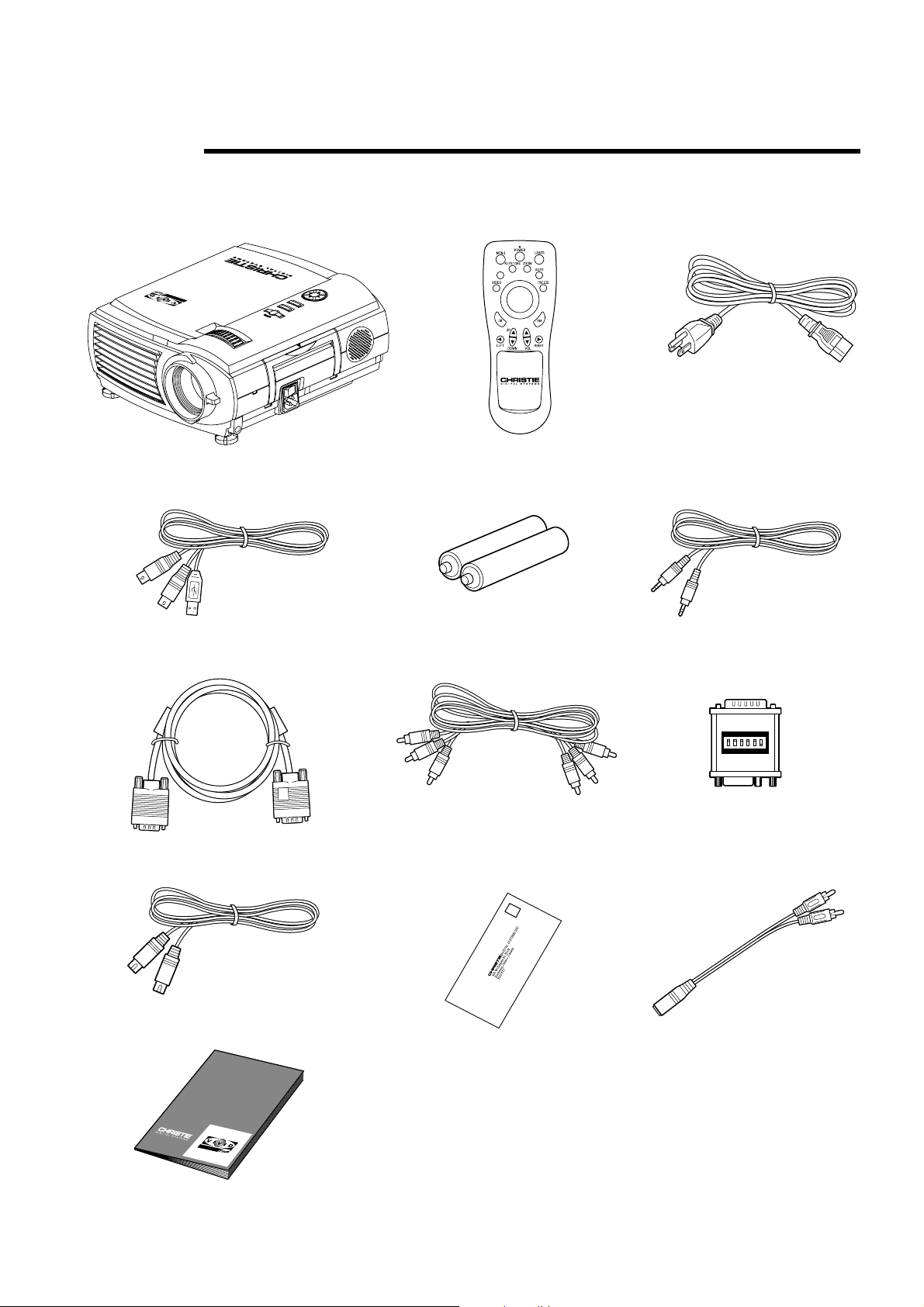
1.2 Components
Vivid Red Projector x 1
Mouse connection cable x 1
RGB cable x 1
Laser pointer remote control x 1
DATA
VOL+
-
AAA batteries x 2
AV cable x 1
Power cable x 1
Audio cable x 1
MAC connector x 1
S-Video cable x 1
Warranty card x 1
Dual male RCA to
female adapter x 1
User's manual x 1
3
Page 6
2. Installation & Setup
2.1 Setting Up Your
Projector
2.2 Screen And
Projection
Distance
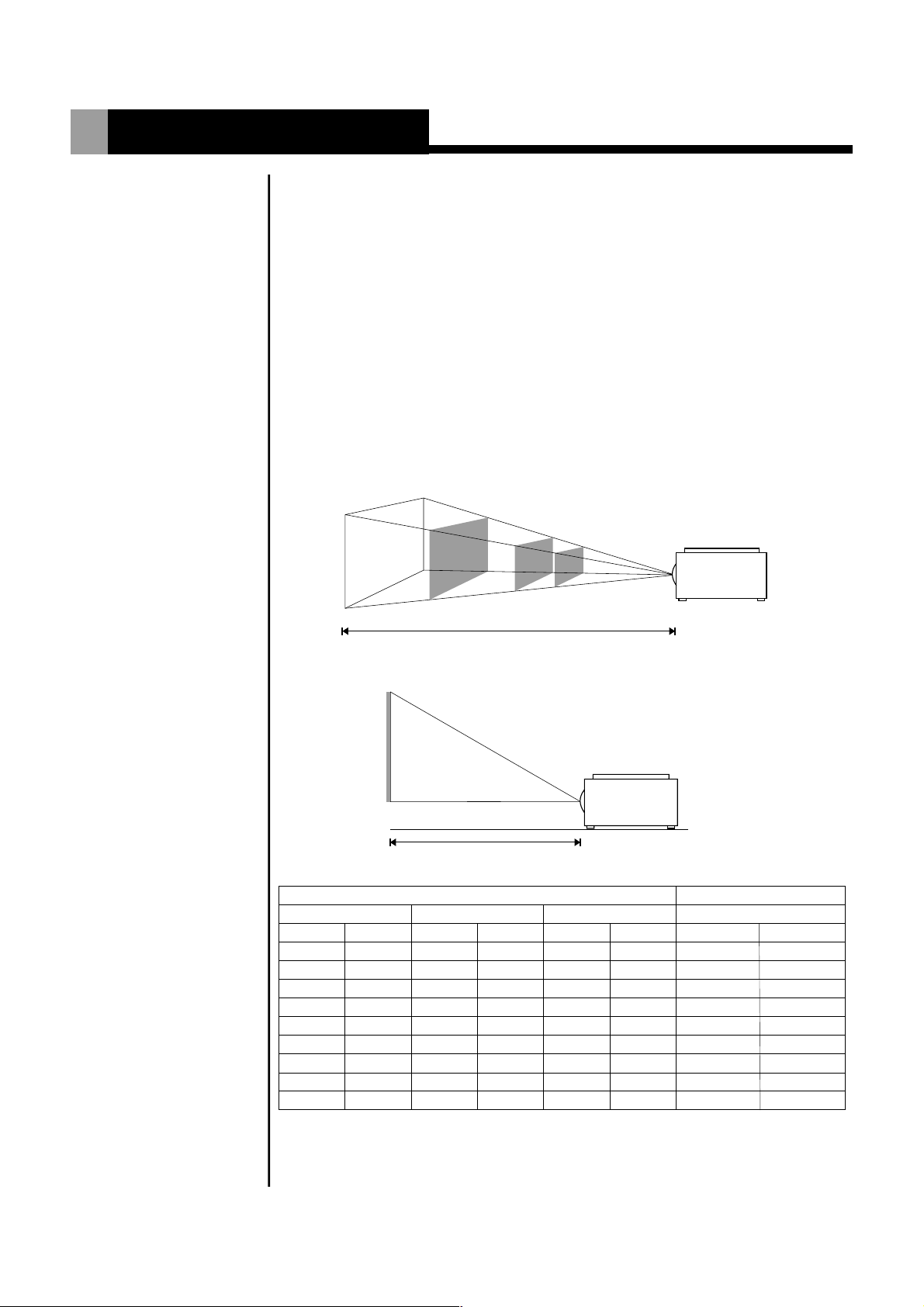
There are three ways to set the projector: front projection, overhead
projection, and rear projection.
1.Determine the image size.
2.Set up a screen or select a non-glossy white wall onto which you can
project your image.
Adjustment
Adjust the height of the projector using the 2 adjusters on the front.
Lift the front of the projector while pressing the adjustment levers on the
front side of the projector.
!
Release the adjustment levers to fix the adjusters in position when
the desired angle is reached.
!
For fine-tuning, turn the adjusters.
300"
100"
40"
30"
~1.2-1.6m
~12 - 16m
~4-5.3m
Projection distance (L)
~1.6-2.1m
Screen Size
(inch)
30
40
60
80
100
150
200
250
300
Screen top
Screen bottom
Projection distance (L)
Screen Size
(cm)
76
102
152
203
254
381
508
635
762
(inch)
18
24
36
48
60
90
120
150
180
Height Width
(cm)
46
61
91
122
152
229
305
381
457
(inch)
24
32
48
64
80
120
160
200
240
(cm)
61
81
122
163
203
305
406
508
610
Projection Distance (L)
(ft)
3.9- 5.12
5.12- 6.9
7.9-10.5
10.5-14.1
13.1-17.4
19.7-26.2
26.2-35.1
32.8-43.6
39.3-52.5
(m)
1.2 - 1.6
1.6 2.1
-
2.4 3.2
-
3.2 4.3
-
45.3
-
68
-
8 10.7
-
10 13.3
-
12 16
-
4
Page 7
Installation & Setup
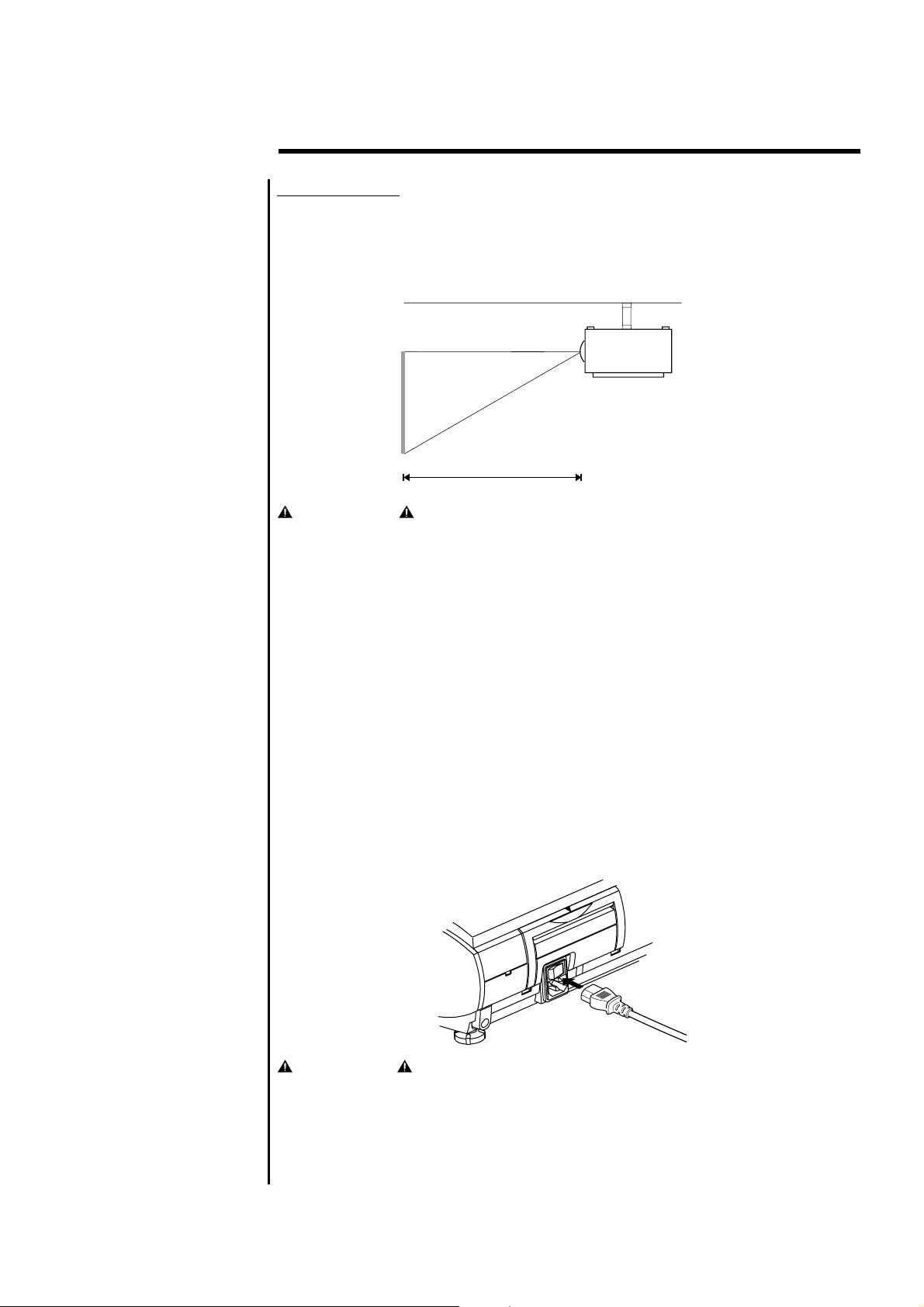
Ceiling Mount
!
If the projector is mounted on the ceiling and the image is upside down, use
the Menu and Up, Down, Left, Right button on your projector keypad or on
the remote control to correct the orientation.
!
The ventilation space shall be 20 cm from the projector foot to the ceiling.
Ventilation
space
Screen top
Screen bottom
Projection distance(L)
WARNING
!
Installing the projector on the ceiling must be done by a qualified
technician, do not attempt to install the projector yourself.
!
Only use the projector on a level, solid surface. If the projector falls to
the ground, the user may be injured and the projector severely
damaged.
!
Do not expose the projector in the moisture, dust, or smoke. This will
harm the projected images.
!
Make sure there is adequate ventilation around the projector. Do not
cover the vents on the side, front or bottom of the projector.
!
Do not use the projector where the temperatures vary greatly. The
projector must be used at temperatures between 32 F (0 C) and 95 F
0
(35 C).
0
2.3 Power
Connection
5
Plug the projector's power cord into the input socket located on the right side
of the projector, plug the three-pronged end of the power cord into a
grounded AC outlet.
CAUTIONS
When the projector is turned off, the fan will continue to run for
approximately 12 seconds to ensure that the projector and the lamp is
cooled down. To avoid thermal stress to the lamp, do not unplug the
power cord while the cooling fan is running.
0
Page 8
Installation & Setup
2.4 External
Connection
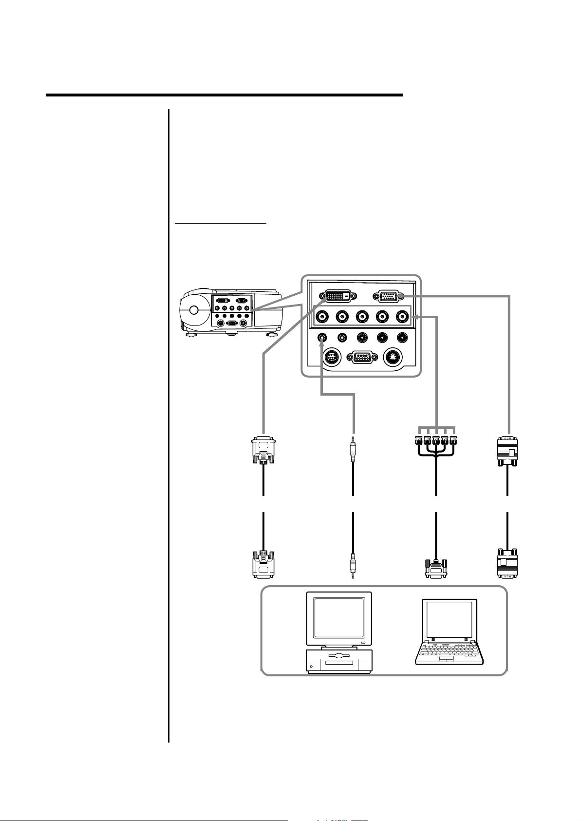
2.4.1 Connecting to
a Personal
Computer
The rear panel of the projector provides the variety of inputs. The
projector can be connected to a computer, video, DVD player, laser disc
player, etc.
The projector can connect to a computer capable of VGA, SVGA, XGA,
SXGA and UXGA output.
Turn off the projector and computer before making any connections or
disconnections.
Connecting a PC
!
Use the supplied cable to connect your PC to the projector.
!
Turn on the projector and the computer.
COMPUTER
G-Y
B/B-Y
L- AUDIO -R VIDEO
To5-plug BNC
terminal
(used whenusing
5-plug BNCinput
to preventloss of
image quality)
R/R-Y
ToRGB terminal
(this connection
enables PC
images tobe
projected)
ToDIGITAL RGB
terminal
(canbeusedwhen
thePChasaDVI-D
terminal)
DVI
H/C.SYNC.
V.SYNC.
AUDIO OUT
PC AUDIO
MOUSE RS232C S-VIDEO
ToAUDIO
terminal
(sound canbe
produced)
ToDIGITAL RGB
output terminal
( DVI-Dterminal)
DIGITAL RGB
cable (optional)
Stereo audio
cable (supplied)
Tosound output
terminal
5-plug BNC
cable (optional)
ToRGB output
terminal
ToRGB output
terminal
RGB cable
(supplied)
NOTE:
!
If the computer output is a 5-plug BNC type, use the 5-plug BNC computer
cable.
!
If the computer has a DVI terminal, use the DVI cable to connect to the
DVI port in the projector.
6
Page 9
Installation & Setup
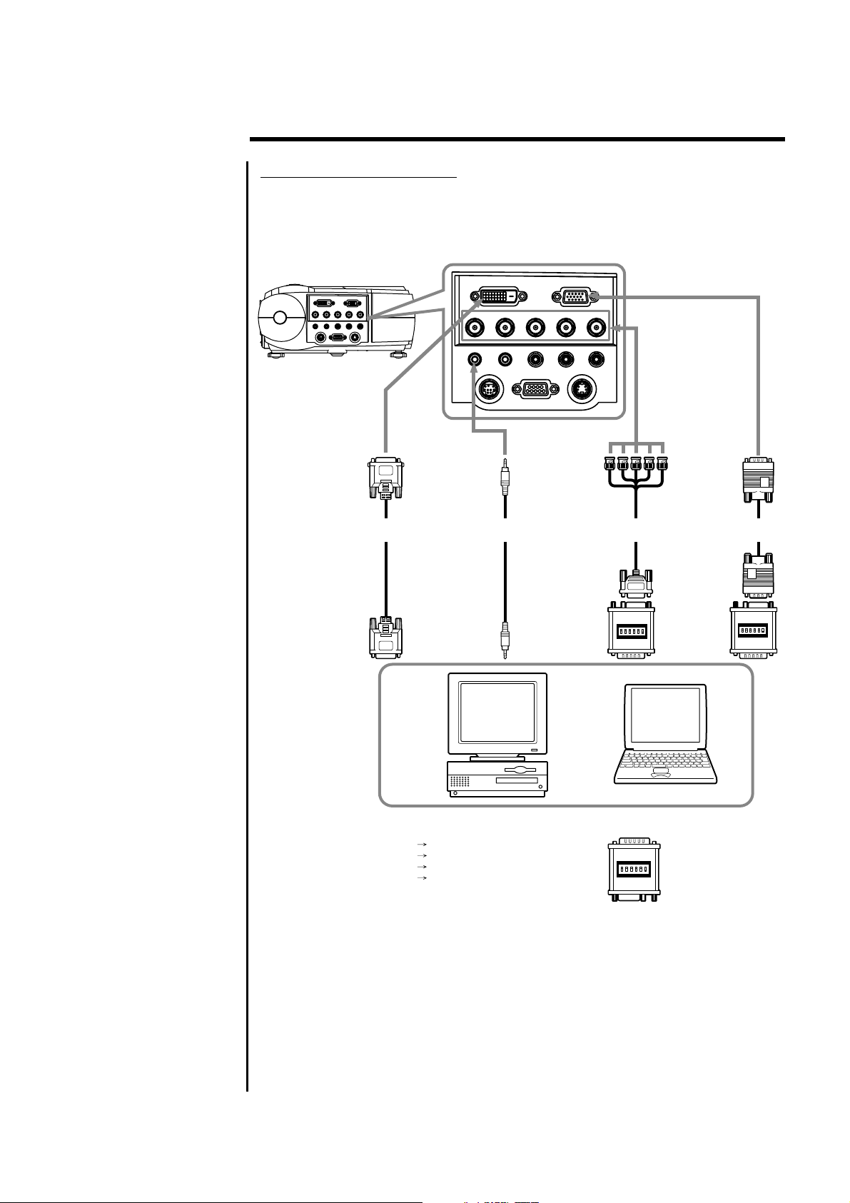
Connecting a Macintosh
!
Use the supplied signal cable and Macintosh adapter to connect your
Macintosh computer to the projector.
!
Turn on the projector and the Macintosh computer.
ToDIGITAL RGB
terminal
(can beused when
thePChasaDVI-D
terminal)
DIGITAL RGB
cable (optional)
ToDIGITAL RGB
output terminal
( DVI-Dterminal)
DVI
H/C.SYNC.
V.SYNC.
AUDIO OUT
PC AUDIO
MOUSE RS232C S-VIDEO
ToAUDIO
terminal
(sound canbe
produced)
Stereo audio
cable (supplied)
Tosound output
terminal
COMPUTER
G-Y
B/B-Y
L- AUDIO -R VIDEO
To5-plug BNC
terminal
(used whenusing
5-plug BNCinput
to preventloss of
image quality)
ToRGB output
terminal
MAC connector
(supplied)
R/R-Y
5-plug BNC
cable (optional)
ToRGB terminal
(this connection
enables PC
images tobe
projected)
ToRGB output
terminal
MAC connector
(supplied)
RGB cable
(supplied)
When using a MAC connector, set the dip switches as follows.
Mac 13" Mode (640 x 480) Switches 1, 5, 6 ON
Mac 16" Mode (832 x 624) Switches 2, 5, 6 ON
Mac 19" Mode (1024 x 768) Switches 3, 5 ,6 ON
Mac 21" Mode (1152 x 870) Switches 1, 2, 3, 5, 6 ON
NOTE:
!
Use the Macintosh adapter to connect a Macintosh computer to the
projector, otherwise it may result in a blank screen.
!
Remove the small cover on the Macintosh adapter. Set the DIP switches
in accordance with the resolution you want to use.
!
When connecting to a Macintosh notebook, a special adapter
(commercially available) may be necessary in addition to the Macintosh
adapter. See Macintosh notebook manual for additional information on
connecting a computer cable.
7
Page 10
Installation & Setup
2.4.2 Connecting to
a Video/ Laser
Disk/ DVD
Player
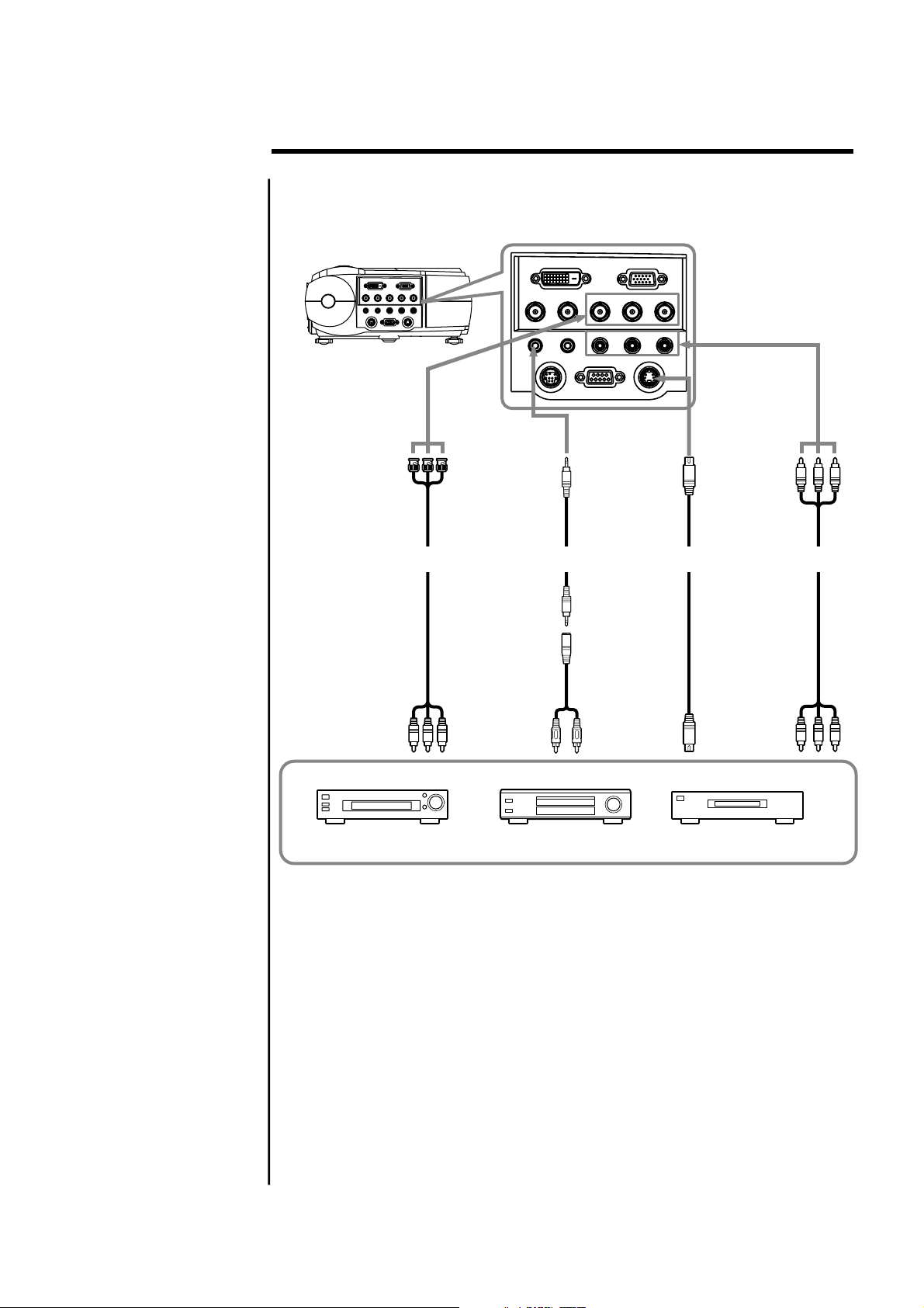
A VCR, a laser disc player, DVD player, or any other compatible video image
source can connect to the projector.
Turn off the projector and video source before making any connections or
disconnections.
The projector can receive composite video, S-Video, or component video.
Connecting a Composite Video Source:
!
If the video source uses a RCA connector, you will need the RCA cable to
connect to the projector. Connect the yellow RCA plug on one end of RCA
cable to the projector's video jack, and connect the other end of the
yellow RCA plug to your video source.
Connecting a S-Video source:
!
If the video source uses S-Video connector, connect one end of the SVideo cable into the S-Video connector of the projector, the other end to
the S-Video-out jack of your video source.
Connecting a Component Source:
!
Insert three ends of a BNC cable into the projector's B/B-Y, G-Y, R/R-Y
jacks. Insert the other ends of the cable into the
jacks on your component video source. (Don't insert any of the cable
ends into the H-Sync and V-Sync jacks.)
B/B-Y, G-Y, and R/R-Y
Connecting an Audio Source:
!
Connect the RCA audio cable to the Audio jacks of the projector: insert
the white plug into L and the red plug into R jack. Connect the other end
of RCA audio cable to your video source.
8
Page 11
Installation & Setup
Connecting to a Video / Laser Disk / DVD Player
ToB/B-Y, G-Y, R/R-Y
terminal
(used toconnect
equipment with
component output
terminal)
RCA-BNC
To
B/B-Y, G-Y, R/R-Y
terminal
(on equipmentwith
component output
terminal)
cable(optional)
V.SYNC.
PC AUDIO
MOUSE
ToAUDIO terminal
(Sound canbe
produced)
Stereo audio
cable(supplied)
Toaudio output
terminal
DVI
H/C.SYNC.
B/B-Y
AUDIO OUT
RS232C
ToS-VIDEO terminal
(used toconnect
equipment withS-Video
output terminal)
COMPUTER
G-Y
R/R-Y
L- AUDIO -R VIDEO
S-VIDEO
S-Video terminal cable
(supplied)
ToS-Video
output terminal
ToVIDEO & AUDIO
L/R terminal
(this connection
enables imageand
sound output)
Tovideo/audio
output terminal
AV cable
(supplied)
Laser disk player Video deck DVD player
9
Page 12
Installation & Setup
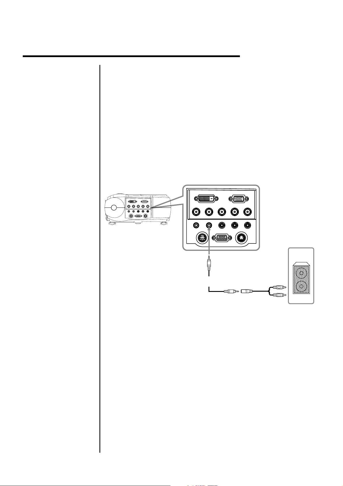
2.4.3 Connecting to
External
Speakers
An external speaker system can connect to the projector to gain maximum
benefit from the projector's built-in sound function.
Turn off the projector and speaker system if they are on.
!
Connecting the stereo audio cable's miniplug to the projector's Audio
Out jack.
!
Connecting the other end of the stereo audio cable to the dual male RCA
to female adapter.
!
Connecting the RCA plugs to the external speakers. Insert the cable's
red plug into the Audio R jack, and the white plug into the Audio L jack.
NOTE: The internal speakers are disabled when an external sound system
is used.
V.SYNC.
PC AUDIO
DVI
H/C.SYNC.
AUDIO OUT
MOUSE
COMPUTER
B/B-Y
L- AUDIO -R VIDEO
RS232C
S-VIDEO
R/R-YG-Y
To Audio Out
terminal
Stereo audio
cable(supplied)
10
Page 13

Installation & Setup
2.5 Mouse Functions
The remote control can be used as a wireless mouse by connecting the
projector mouse port to the computer mouse port.
Connecting the Mouse:
!
Connecting the big end of the PS/2 mouse cable (9 pin) to the projector
mouse port.
!
Connecting the small end of the PS/2 mouse cable (6 pin) to the
computer's mouse port.
!
For a Macintosh computer, connect the USB mouse or PS/2 mouse.
V.SYNC.
PC AUDIO
DVI
H/C.SYNC.
AUDIO OUT
MOUSE
To Mouse PS/2
terminal
COMPUTER
B/B-Y
L- AUDIO -R VIDEO
RS232C
S-VIDEO
R/R-YG-Y
To Mouse (PS/2)
Mouse cable
(supplied)
terminal
To Mouse (USB)
terminal
How to Use the Remote Control as a Wireless Mouse:
!
Right Mouse button
The right mouse button is
marked RM on the right of the
remote control.
!
Left Mouse button
The left mouse button is
marked LM on the left of the
remote control.
!
Moving the Cursor
Use the mouse pointer button
to move the cursor left, right,
up, down.
!
Select Item
Move the cursor to item and
press the LM button.
!
Drag
While pressing the LM button,
press the mouse pointer
button to drag in the desired
direction.
Mouse
pointer
button
Left Mouse
button
VIDEO
MENU
DATA
LM
LEFT
POWER
KEYSTONE
UP
DOWN
ZOOM
VOL -
VOL+
LASER
AUTO
FREEZE
RM
RIGHT
Right
Mouse
button
11
Page 14

3.Operation
3.1 Projector Basics
Front/ Side Features
Zoom lever
Lens
Remote sensor
Height adjuster
Ventilation
Control keypad
Speaker
Handle
Main power switch
AC input
Adjustment levers
Focus ring
Height adjuster
Rear/ Side Features
Security Lock *
Adjustment levers
Height adjuster
I/O terminal panel
Remote sensor
Security Lock Note:
The projector can connect to a commercially available security cable
(Kensington's).
Speaker
12
Page 15

Operation
Bottom Features
Rear foot
Air filter (small)
Air filter (large)
Lamp cover
Lamp cover screw
Control Keypad Features
LAMP
PO
ER
W
1
2
SOURCE
3
MENU
4
5
1. Lamp Indicator
2. Power Button & Power Indicator
Use this button to turn the power on and
off when the main power switch on the
side of the projector is switched on and
the projector is in standby mode.
3. Source Button
Use the button to select a proper
source such as PC, VCR, DVD player,
etc.
4. Menu Button
Displays the menu.
5. Up, Down, Left, Right Button
Use Up, Down to select the menu item
you wish to adjust.
Use Left, Right button to change the
level of selected menu item.
13
Page 16

I/O Terminal Features
Operation
V.SYNC.
PC AUDIO
MOUSE
DVI
H/C.SYNC.
AUDIO OUT
COMPUTER
B/B-Y
L- AUDIO -R VIDEO
RS232C
G-Y
S-VIDEO
R/R-Y
14
Page 17

Operation
3.2 Turning On &
Turning Off The
Projector
LAMP
ER
W
PO
SOURCE
MENU
POWER
LASER
MENU
ZOOM
KEYSTONE
DATA
AUTO
VIDEO
LM
LEFT
FREEZE
RM
UP
VOL+
RIGHT
VOL-
DOWN
Before turning on the projector, make sure the video source is turned on and
the lens cap is removed. Connect the power cord to the projector.
Turning On the Projector:
1. Turn on the main power switch on the side of the projector, the projector
will go into its standby mode and the power indicator will glow orange.
2. Press the Power button on the projector control keypad or on the remote
control, the power and lamp indicator will glow green and the projector
will be ready to use.
Turning Off the Projector:
1. Press the Power button on the projector control keypad or on the remote
control, the message as below will show on screen. Press the Left button
to move the cursor to "Power Off" and press Menu button to turn off the
projector, and the power indicator will glow orange. After the projector is
turned off, the cooling fan will continue to run for 120 seconds and then
stop.
POWER BUTTON WAS PUSHED!
Movethecursorto"PowerOff"
and press MENU button
to turn projector off.
Power Off Cancel
NOTE:
NOTE:
2. Switch off the main power switch on the side of the projector and unplug
Do not disconnect the power cord or switch off the main power
switch when the cooling fan is still running.
If mis-press the Power button, move the cursor to "Cancel" by
pressing the Right button and press Menu button to resume. The
message will disappear after 10 seconds if there is no response.
the power cord. The power indicator will go out.
15
Power and Lamp Status Indicators Messages Chart:
Condition Power Indicator Lamp Indicator Description
Main power switch on Orange (side)
Power On Green Green
Power Standby Orange Cooling down Flashing green - Flashing for 120 seconds
Lamp life (1500 hrs) Green Flashing Green
System error Orange Flashing Red Projector in power standby mode
(1 sec interval) and cannot be turned on
Temperature error Orange Flashing Red Projector in power standby mode
(2 sec interval) and cannot be turned on
Lamp error Orange Flashing Red Projector in power standby mode
(4 secs interval) and cannot be turned on
Fan error Orange Flashing Red Projector in power standby mode
(8 secs interval) and cannot be turned on
Lamp timer, message of
reaching its limit. Please replace the
lamp as soon as possible."
on screen when the lamp reaches
1400 hours usage ; "Lamp Expired"
When lamp reaches 1500 hours
usage.
"The lamp is
appears
Page 18

Operation
3.3 Basic Operation
Adjusting the Tilt Feet
1. Lift the front edge of the projector.
2. Press the adjustment levers on the front of the projector and hold the levers.
3. Lower the front of the projector to desired height and release the lever to
lock the tilt feet.
4. Fine-adjust the height, use the height adjusters on the front of the projector.
1
2
4
3
2
Loading the Batteries (2 size AAA betteries)
1. Open the battery compartment cover on
the back of the remote control unit in the
direction shown.
2. Insert two size AAA batteries, ensure that
the positive and negative terminals are
aligned correctly.
3. Close the battery cover in the direction
shown.
Batteries Note:
!
Replace the battery as soon as they run out.
!
Remove the batteries if the remote control unit is not used for a long period
of time.
!
Dispose the used batteries in accordance with local recycling and waste
disposal ordinances.
!
When changing the batteries, use two new batteries of the same type.
16
Page 19

Operation
Selecting the Desired Image
Press the Video button on the remote control to cycle through the video
inputs.(Composite, S-Video, Component)
Press the Data button on the remote control to cycle through the RGB
graphics inputs. (RGB, Component, DVI)
Press the Source button on the control keypad to start source auto scan
through composite Video, S-Video, component video (if connecting BNC
with video source), Analog RGB, component RGB (if connecting BNC with
computer source), and DVI.
LAMP
ER
Source
button
W
PO
SOURCE
MENU
Data button
Video
button
VIDEO
MENU
DATA
KEYSTONE
POWER
ZOOM
LASER
AUTO
FREEZE
LM
UP
LEFT
DOWN
Adjusting the Focus
Use the focus ring to obtain the best focus.
Adjusting the Zoom of the Image
Use the Zoom lever to adjust the image size on the screen.
Use Keystone correction to keep the image square.
Zoom lever
Focus ring
VOL-
RM
VOL+
RIGHT
17
Page 20

Operation
1
Zoom
button
POWER
LASER
MENU
ZOOM
KEYSTONE
AUTO
DATA
VIDEO
LM
LEFT
FREEZE
2
RM
VOL+
VOL-
Vol+ / Vol-
RIGHT
UP
DOWN
1. Press the Zoom button on the remote control.
2. Use Vol+ button to enlarge the Image, Volbutton to return the enlarged image to its
original size. The zoom ratio can be 10 times
the original image size.
3. Move the image to the area you wish to see
by using the Up/ Down, Left/ Right buttons on
the remote control.
4. Press zoom button again to cancel the
enlargement and return to the normal status.
LAMP
ER
W
PO
SOURCE
MENU
3
Up, Down,
Right, Left
POWER
LASER
MENU
ZOOM
KEYSTONE
AUTO
DATA
VIDEO
LM
LEFT
FREEZE
RM
UP
VOL+
RIGHT
DOWN
VOL-
buttons
Correcting the Keystone Distortion
Press the keystone button, And adjustment scale is displayed.
POWER
Adjusting Digital Zoom of the Image
Keystone
button
MENU
DATA
VIDEO
KEYSTONE
LASER
ZOOM
AUTO
FREEZE
LM
LEFT
Press button to adjust the upper part of the image;
Vol+
RM
UP
VOL+
RIGHT
DOWN
VOL-
Use Vol- button to correct the lower part of the image.
Adjusting the Volume
Press the Vol+/ Vol- buttons on the remote control to increase or decrease
the volume.
18
Page 21

Operation
3.4 Remote Control Features
Front
1
1. Infrared Transmitter
Direct the remote control to the remote sensor
on the projector.
2. Laser Pointer
Beams a laser light when "Laser" button is
pressed.
3. Power Button
While the power is applied, main power switch
on the side of the projector is switched on, use
this button to turn on/ off your projector.
4. Laser Button
Press and hold this button to activate the laser
pointer.
5. Menu Button
(1) Displays the menu for various adjustment.
(2) Return to the sub-menu.
(3) Exit from the menu
6. Video Button
Press this button to select a proper video
source. The video sources sequence is:
Composite video, S-Video, and Component
video.
7. Data Button
Use the button to select a proper data source.
The data sources sequence is Analog RGB,
component RGB, and DVI.
8. Keystone Button
Press the keystone button and a keystone scale
shows up in the screen, press "Vol+", "Vol-"
buttons to correct the keystone distortion, and
make the image square.
2
POWER
DATA
VIDEO
MENU
KEYSTONE
5
8
7
ZOOM
LASER
AUTO
FREEZE
6
13
15
17
LEFT
LM
UP
DOWN
VOL-
RM
VOL+
RIGHT
9. Zoom Button
Press this button and a zoom ratio scale pops
up. Use "Vol+", "Vol-" button to select the zoom
ratio, "Up", "Down", "Left", "Right" buttons to
move the center of the image.
10. Auto Button
Press this button to auto adjust the image.
11. Freeze Button
This button will freeze a picture. Press again to
resume motion.
2. Mouse Pointer Button
1
When you are in computer mode, this button
works as a computer mouse.
13. Left Mouse (LM) Button
This button corresponds to the left mouse click
when in computer mode.
14. Right Mouse (RM) Button
This button works as the right mouse click when
in computer mode.
15. Left Button
Adjust the value in the sub-menu.
6. Right Button
1
(1) Adjust the value in the sub-menu.
(2) Move to the sub-menu.
17. Up/Down Button
Select the menu of the item you wish to adjust.
18. Volume up/Volume down (Vol+/Vol-)
Button
Adjust the volume scale when menu is not
displayed.
3
4
9
10
11
12
14
16
18
19
Page 22

Range of Use of the Wireless Remote Control
Operation
Within 10 m (11 yards)
VIDEO
DATA
LEFT
UP
DOWN
VOL-
VOL+
RIGHT
MANU
LM
KEYSTONE
POWER
ZOOM
LASER
AUTO
RM
FREEZE
15
3.5 Using The Menu
ER
W
LAMP
PO
MENU
SOURCE
1. Press button.
Menu
The menu screen is displayed.
Within 10 m (11 yards)
15
FREEZE
RM
AUTO
LASER
ZOOM
POWER
KEYSTONE
DATA
MANU
RIGHT
VOL+
VOL-
DOWN
UP
LM
LEFT
VIDEO
Example
2. Select the menu item you wish to adjust with buttons on the
: When RGB is selected for the input source.
Up /Down
remote control or on the control keypad
3. Press the button to go into the sub-menu
4. Use button to adjust the sub-menu scale.
5. Press again to go back to the previous level.
Right
Left / Right
Menu
20
Page 23

Operation
3.5.1 Adjusting the
Image
RGB Image Menu
Video Image Menu
!
Brightness
Adjust the brightness of the picture. Press Left button to make it darker,
Right button to make it brighter.
!
Contrast
Adjust the image contrast by pressing Left button to make it weaker,
Right button to make the contrast stronger.
!
H position
Adjust the picture horizontal position by pressing Left and Right buttons.
!
V position
Adjust the picture vertical position by pressing Left and Right buttons.
!
Phase (RGB only)
Remove the last indications of noise or shaded areas that remain on the
screen after completing the adjustment.
!
Frequency (RGB only)
Control the horizontal size to match the projector to the computer.
!
Color (Video only)
Adjust the depth of the colors. Press Left button to make it lighter, Right
button to make the color deeper.
!
Tint (Video only)
Adjust the tint by pressing Left button for a greenish tint, Right button
for a reddish tint.
!
Detail (Video only)
Control the detail of the image. Press Left button to make it softer, Right
button make the image sharper.
21
Page 24

3.5.2 Adjusting
Advanced
Control
Operation
RGB Advanced Menu
Video Advanced Menu
!
Sharpness
Adjust the sharpness level by pressing Left/ Right buttons to choose.
!
User Red
Adjust the strength of the red color. Press Left button to make it weaker,
Right button to make it stronger.
!
User Green
Adjust the strength of the green color. Press Left button to make it
weaker, Right button to make it stronger.
!
User Blue
Adjust the strength of the blue color. Press Left button to make it
weaker, Right button to make it stronger.
!
Scaling (RGB only)
Fill Fill the image to the whole projected area.
Aspect Enlarge the image while maintaining the original aspect.
1:1 Original input resolution and size.
!
Scaling (Video only)
Select the best aspect mode to display your video image.
Normal as standard 4:3 aspect.
Anamorphic as up and down stretched.
Zoom as all 4 sides stretched.
Wide as left and right stretched and keep it as 16:9 aspect.
22
Page 25

Operation
3.5.3 Selecting the
Options
Options Menu
!
OSD
Choose the OSD position to be in the left/middle/right corner of
upper/middle/lower part of the screen.
!
Language
Select the languages of menu display: English, German, French,
Spanish, and Chinese.
!
BNC
Select the source type when connecting the BNC terminal. When the
input source is the computer, select RGB. When the input source is the
video, select YUV.
!
Image Orientation
Select "Inverted" to turn the image upside down when you put the
projector on the ceiling.
!
Rear Projection
Select "On" to reverse the image when you put the projector behind
the translucent screen.
23
Page 26

3.5.4 Setting the
Utilities
Operation
Utilities Menu
!
OSD Timeout
Select how long you wish your OSD will be displaying on the screen.
!
OSD Background
Select the OSD background to be opaque or translucent.
!
Freeze Frame
Freeze the picture by selecting "On", cancel it by selecting "Off".
!
Keystone
Correct the keystone distortion. Press Left/ Right buttons to correct the
keystone distortion, and make the image square.
The maximum keystone correction is 15 degrees upward and
downward with the projector placed horizontally on the ground plane.
!
Zoom
Use the zoom scale to enlarge the image or to return the enlarged
image to its original size. The zoom ratio can be 10 times the original
image size.
Move the image to the area you wish to see by using the Up/Down,
Left/ Right buttons on the remote control or control keypad.
!
Lamp Life
Indicates how many hours the current lamp has been used.
!
Factory Reset
Back to the factory default.
24
Page 27

Operation
3.5.5 Setting the
Audio
!
Mute
Mute the sound by selecting "On", back to normal by selecting "Off".
Source
!
Select the audio source from video input or RGB input.
!
Mode
Set the audio to be mono or stereo.
Volume
!
Adjust the volume by pressing Left button to decrease the volume,
Right button to increase the volume.
Bass
!
Adjust the power of bass sound. Press Left button to decrease the
strength, Right button to increase the strength.
Treble
!
Adjust the treble level. Press Left button to decrease the level, Right
button to increase the level.
Balance
!
Adjust the balance of left and right speaker. Press Left button to
increase the left speaker sound, Right button to increase the right
speaker sound.
Audio Menu
3.5.6 Selecting the
Source
3.5.7 Selecting the
Video Standard
Source Menu
Select the connected source type. When connecting the computer, choose
from D-Sub, Component RGB or DVI source. When connecting the video,
choose from S-Video, Composite video or Component Video.
Standard Menu - Video only
Select the video broadcasting format. Set on Auto Standard for normal use.
25
Page 28

4. Maintenance & Care
4.1 Warnings and
Guidelines
Labels & Markings
Protection Location
WARNING
Never look directly into the projector lens. The extremely high
brightness of the projector can cause permanent eye damage.
Observe and follow all warnings and instructions marked on the projector.
This symbol warns the user that the presence of uninsulated
voltage within the unit may be sufficient to constitute the risk of
electric shock. Therefore, it's dangerous to make any kind of
contact with any part inside of the projector.
This symbol alerts the user that important operation and
maintenance instructions have been provided. This information
should be read carefully to avoid problems.
"
Operate the projector in an environment which meets the operating range
specification in Section 6, Specifications. Do not operate the projector
close to water, such as near a swimming pool.
"
Do not place the projector on an unstable cart, stand or table. If the
projector is to be ceiling mounted, only use the Christie-approved ceiling
mount fixture.
"
A projector and cart combination should be used with care. Sudden stops,
excessive forces, and uneven surfaces may cause the projector and cart
combination to overturn.
Lamp and Filter
Replacement
"
Always turn off the power switch before replacing the lamp. Allow the unit
to cool off for at least one hour before replacing the lamp. Replacing the
lamp according to the directions in the operational manual. Burns or
electrical shock may occur if the replacement is performed incorrectly.
"
Do not tamper with the lamp interlock mechanism. Electrical shock or
other damage may occur if the interlock mechanism does not operate
correctly.
"
When the lamp is removed, handle it with care, and ensure it is not
subjected to impact. Do not use the lamp unit if it has been subjected to
shock or scratched. Contact your sales office for repair.
"
Do not touch the terminal end of the lamp unit or the screws, which secure
the connector. Even if screws become loose, do not attempt to perform the
repair operation yourself and contact your sales office. This condition may
result in fire, electrical shock or other damage.
WARNING
If you continue to use the lamp after the lamp expired message has
been displayed on the screen, the lamp bulb may shatter and pieces of
glass may scatter inside the projector and out into the room. Do not
touch glass as it may cause injury. Contact your sales office for lamp
replacement.
"
Replace the air filter every time the lamp is replaced. If this filter is not
replaced, air flow may be restricted and cause the projector to overheat.
26
Page 29

Maintenance & Care
Power Cord and
Attachments
"
Only use attachments or accessories recommended by Christie, such as
the specific power cord supplied. Use of other attachments or
accessories with this projector may result in the risk of fire, shock or
personal injury.
WARNING
Use only the AC power cord supplied. Do not attempt operation if the
AC supply and cord are not within the specified voltage and power
range.(see section 6)
"
Do not allow anything to rest on the power cord. Locate the projector
where the cord can not be abused by persons walking on it or objects
rolling on it.
"
Operate the projector at the specified voltage only. Do not overload power
outlets and extension cords as it can result in fire or shock hazards.
"
The projector is equipped with a three wire plug having a third (grounding)
pin. This is a safety feature. If you are unable to insert the plug into the
outlet, contact an electrician to have the outlet replaced. Do not defeat
the safety purpose of the grounding-type plug.
"
Always turn off the power before connecting cables and other
connections. Read the instruction manuals of the other equipment
connected to the projector thoroughly. Fire or electrical shock may occur
when these operations are performed if the main power is turned on.
"
Do not touch the electrical plug when there is thunder or lighting.
Touching the projector in this condition may cause electrical shock.
"
Do not place the electrical cord near a heater or other objects that
generate high temperatures.
"
Inspect the electrical plug periodically. Fire or electrical shock may occur
if the insulation on the electrical plug becomes defective.
"
Always pull out the electrical plug when the unit is not used for a long
period of time. If the plug is not removed, the insulation may deteriorate
and cause electrical shock or a fire due to current leakage.
"
Always grasp the plug firmly and never pull on the electrical cord to
remove the electrical plug from the wall outlet. If the cord is pulled, it may
be damaged and cause fire or electrical shock.
"
Never touch the electrical plug with wet hands.
27
Page 30

Ventilation
Maintenance & Care
"
Before unplugging the power cord, make sure the internal lamp cooling
fans have shut off. The fans automatically shut off when the projector has
adequately cooled down.
"
Slots and openings in the projector provide ventilation. To ensure reliable
operation of the projector and to prevent overheating, these openings
must never be blocked or covered. The projector should never be placed
near or over a radiator or heat register. The projector should not be placed
in an enclosure unless proper ventilation is provided. Do not place the unit
on top of a carpet or cushion.
"
Always place the projector in a well-ventilated area to ensure proper
airflow (30 cm or 12 inches away from any wall is recommended)
"
Do not push objects of any kind into the projector through the ventilation
openings. They may touch dangerous voltages or short-out components
resulting in a fire or shock hazard. Do not spill liquids of any kind into the
projector. Should an accidental spill occur, immediately unplug the
projector and have it serviced by a qualified service technician.
"
Never place the projector in a location subject to steam, oily smoke, heat
or humidity. This may cause fire or electrical shock.
Servicing
"
Ensure that the projector has warmed up to room temperature before
using it. Dew or moisture condensation may be produced inside the
projector if there is a temperature difference between the inside and
outside of the unit. The condition may cause electrical leakage, shock or
fire.
"
If any of the following conditions exist, immediately unplug the projector
from the power outlet and refer service to qualified service personnel.
- The power cord has been damaged.
- The internal cooling fans do not come on when the projector is first
turned on.
- Liquid has been spilled in the projector
- The projector has been exposed to excessive moisture.
- The projector does not operate normally.
- The projector has been dropped or the case has been damaged .
- Projector performance has deteriorated.
- There is an abnormal condition (i.e.: smoke coming from projector)
!
Do not loosen any screws that are indicated by the arrow mark. The unit
contains internal parts, which have high voltage or high temperatures.
Touching these parts may cause electrical shock or severe burns.
!
Do not attempt to service the projector yourself. All servicing must be
performed by a qualified Christie service technician only. If replacement
parts are required, it is important that only Christie-approved parts are
used. Other parts may result in fire, electric shock or risk of personal injury.
28
Page 31

Maintenance & Care
Other Items
4.2 Cleaning
"
Do not turn on the electricity or the lamp when the lens cap is attached.
The lens cap will become deformed due to the heat of the lamp and may
cause fire or severe burns.
"
A laser beam is projected if the laser button in the accessory wireless
remote control is pressed. Never look directly into the laser beam. The
laser beam may cause damage if it enters the eyes directly.
Cleaning the Case
Wipe lightly with a soft, dry cloth. If the case is very dirty, clean the case with
a soft, dampened cloth using mild commercial cleaner and finish with a dry
cloth. Do not use liquid or aerosol cleaners.
Cleaning the Lens
To prevent scratching the lens, clean the lens only if absolutely required.
Clean the lens with a commercially available blower or cleaning paper gently
in a circular motion.
Cleaning the Lamp
It is important to never touch the glass surface of the lamp, as the oil imprint
will seriously degrade lamp performance. If the surface of the lamp is
accidentally touched, clean carefully with a lint-free cloth moistened with
isopropyl alcohol.
4.3 Replacing the
Lamp
When the lamp reaches the end of its service life, the image will become
darker and colors lose their richness. When the lamp has been operating for
1400 hours or longer, the lamp status LED indicator will flash green, and the
message "The lamp is reaching its limits. Please replace the lamp as soon as
possible" will be displayed on the screen. Even though the lamp may still be
working, replace the lamp to maintain optimal projector performance. When
the lamp has been operated for 1500 hours, the message " LAMP
EXPIRED!!" will be shown on the screen, replace the lamp immediately.
CAUTION
DO NOT TOUCH THE LAMP immediately after it has been used. It will be
extremely hot. Allow the fan to finish its cooling process, then turn the
projector off, and disconnect the power cord. Allow at least for
the lamp to cool down before handling.
DO NOT REMOVE ANY SCREWS except the lamp cover screw and two
lamp housing screws. Removing other screws could result in electric
shock to the user.
If continuing to use the lamp after the replacing lamp message has been
displayed on screen, the lamp bulb may shatter, and pieces of glass
may scatter inside the projector and out into the room. Do not touch
them as the pieces of glass may cause injury. If this happens, contact
your dealer for lamp replacement.
one hour
29
Page 32

Maintenance & Care
To Replace the Lamp:
1. Loosen the lamp cover screw and remove the lamp cover.
2. Loosen the two screws securing the lamp housing. Remove the lamp
housing by pulling on the handle.
3. Insert a new lamp housing until it is plugged into the socket.
4. Secure it in place with the two screws.
5. Re-attach the lamp cover.
6. Tighten the lamp cover screw.
7. Reset the lamp timer.
To Reset the Lamp Timer:
1. Press Left button, Menu button, and Up button within one second on the
control keypad or remote control to enter engineering menu as shown:
4.4 Replacing the
Air Filter
2. Go to lamp reset sub-menu and move the cursor to Reset option. Press
Right button to select.
3. Lamp timer will reset to 0 hour usage.
There are two air filter sponges in the bottom of the Vivid Red projector to
capture dust or dirt and should be replaced whenever the lamp module is
replaced. The temperature will rise and the lamp will fail to light when the air
filters inside of the projector become dirty and clogged. Replacement will be
required more often if the projector is used in the a particularly dusty
environment.
1. Unplug the power cord from the socket.
2. Remove the small filter holder and
unscrew the big air filter screw.
3. Detach the air filters.
4. Replace the air filters.
5. Install the air filters.
6. Re-install the filter covers.
3030
Page 33

5. TROUBLESHOOTING
5.1 Common Problems & Solutions
Problems
Does not turn on
No image
Image is blurred
Image is too dark
Check These Items
"
Check that the power cable is plugged in and that power switch on the
side of projector is switched on, and power button on the projector
control keypad or remote control is pressed on.
"
Check that the projector is on.
"
Use the menu to select the source (Composite video, S-Video,
Component video, Analog RGB, Component video or DVI). See page 25.
"
Ensure the cables are connecting correctly.
"
Use the menu to adjust the brightness and contrast. See page 21. Or
reset the settings to factory preset level using the Factory Reset option
on the Utilities menu. See page 24.
"
Remove the lens cap.
"
Adjust the focus. See page 17.
"
Ensure the distance between the projector and the screen is within the
focus range of the lens. See page 4.
"
Adjust the contrast or brightness in the Image menu properly. See page
21.
No sound
Remote control does not
work
Status indicator is lit or
blinking
"
Ensure the cables are connecting properly. See page 10.
"
Make sure the Mute option in Audio menu is selected Off. See page 25.
"
Install new batteries. See page 16.
"
Make sure there is no obstacles between you and the projector
receivers.
"
Stand within the distance of remote control usage range. See page 20.
"
See the Power and lamp indicator message chart on page 15.
31
Page 34

6. SPECIFICATION
6.1 Specifications
Model Number: Vivid Red
Display Technology 0.9" LCOS D-ILA x 3
Resolution SXGA (1365 x 1024)
Projection Lamp 200W UHP lamp, 1500 hours typical
Brightness 1100 ANSI lumens typical
Brightness Uniformity 85% typical
Contrast Ratio 500:1 (full on / full off) typical
Aspect Ratio Standard 4:3 and wide screen 16:9
Projection Lens (Zoom) F=2.5, f=36 - 45mm, zoom ratio1.3, Manual Focus /Manual Zoom
Screen Size 30" - 300"
Throw Distance 1.2 - 16m
Keystone Correction 15 degree
Digital Zoom 10X
Remote Control Full functionality IR remote with mouse control and laser pointer
Video Compatibility NTSC / PAL / PAL-M/ PAL-N / PAL 60 / HDTV 720p
Computer Compatibility UXGA / SXGA / XGA / SVGA / VGA / MAC
H-Sync Range 15 - 100 kHz
V-Sync Range 50 - 100 Hz
Dot Clock 162 MHz
Sound Output 2W Stereo x 2
Terminals Inputs PC Input: D-sub15 pin x 1
Audio Input: RCA x 2
Video Input: RCA x 1
S-Video x 1
Component Input x 1
Digital Computerx1(DVI)
Mouse port
Terminals Outputs Audio Output: Mini jack x 1
Voltage 100 - 240 VAC, 50 - 60 Hz universal
Power Consumption 380 W (Max)
Dimensions 12.7"(L) x 11.5"(W) x 5.3"(H)
324 mm (L) x 293 mm (W) x 136 mm (H)
Weight 5.8 kg (12.8 lbs.)
Approvals FCC Class B, UL, cUL, CE, TUV
Audible Noise 38dB typical
Accessories List User Manual, Laser Pointer remote control, Power/ Computer/ Stereo
Audio / S-Video / Composite Video cable, Monitor Adapter for Macintosh
(DIP-SW), Dual Male RCA to Female 3.5mm adapter, PS/2 - USB mouse
cable
/ NTSC4.43 SECAM /
32
Page 35

7. Appendices
7.1 Glossary
Aspect ratio
Brightness
Contrast (ratio)
Component Video
Composite Video
Keystone
Lumen
NTSC
OSD
PAL
This appendix defines the specific terms used in this manual.
The ratio of the width of an image to its height.
The balance of light and dark shades in an image.
The degree of difference between the lightest and darkest areas of the
image.
A high-end digital(YCrCb) and analog(YPrPb) component video signal.
The output of
synchronization, luminance and color signals on one output cable.
A distortion of the image which occurs when the top and bottom borders of
the image are unequal in length.
The unit of measure for the amount of visible light emitted by a light source.
A 525-line video format of some video tape and disk players. NTSC is widely
used in North America, Mexico and Japan.
(On Screen Display) Menu. A list of selectable options displayed on the
screen.
A 625-line video format used in Western Europe, India, China, Australia,
New Zealand and parts of Africa.
video tape and some computers which combines
Pixel
Resolution
RS-232
S-Video
SECAM
Tint
Zoom
The smallest discernible element of data from a computer generated image.
A measure of the maximum amount of horizontal and vertical pixels
contained in an image. Such as 1280 x 1024 (called SXGA)
A common asynchronous data transmission standard recommended by the
Electronics Industries Association (EIA). Also called serial communication.
A type of video signal from certain video tape players and video
equipments. S-Video transmits luminance and color separately, typically
producing a higher quality display than composite video.
A video format of
Eastern Europe, Russia and parts of Africa. SECAM signals are similar in
resolution and frequency to PAL signals.
Balance of red-to-green necessary for realistic representation of NTSC
signals.
The adjustment of image size.
some video tape and disk players, used primarily in France,
33
Page 36

7.2 Menu Tree
Appendices
Image
Advanced
Options
Utilities
Audio
Source
Standard
RGB Image Signals
Brightness
Contrast
H Position
V Position
Phase
Frequency
Video Image Signals
Brightness
Contrast
H Position
V Position
Color
Tint
Detail
RGB Image Signals
Sharpness
User Red
User Green
User Blue
Scaling
Video Image Signals
Sharpness
User Red
User Green
User Blue
Scaling
Fill Aspect 1:1
Normal Anamorphic Zoom Wide
OSD
Language
BNC
Image Orientation
Rear Projection
OSD Timeout
OSD BG
Freeze Frame
Keystone
Zoom
Lamp Life
Factory Reset
Mute
Source
Mode
Volume
Bass
Treble
Balance
Auto Source
Composite Video
S-Video
Component Video
Analog RGB
Component RGB
DVI
Video Image Signals
Auto Standard
NTSC
NTSC 4.43
PAL
PAL M
PAL N
PAL 6 0
SECAM
English German French Spanish Chinese
RGB YUV
Upright Inverted
On Off
Opaque Translucent
On Off
On Off
Video RGB
Mono Stereo
34
Page 37

Appendices
7.3 Throw Distance
300
250
200
Screen
width (in)
150
100
50
0
0 102030405060
Proj ection Di stance (ft)
Screen Size
Screen Size
(inch)
30
40
60
80
100
150
200
250
300
(cm)
76
102
152
203
254
381
508
635
762
Height Width
(inch)
18
24
36
48
60
90
120
150
180
(cm)
46
61
91
122
152
229
305
381
457
OPERATING RANGE
(inch)
24
32
48
64
80
120
160
200
240
(cm)
61
81
122
163
203
305
406
508
610
Throw distancemeasured
from screento front feet
(centers) ofprojector
Projection Distance (L)
(ft)
3.9- 5.12
5.12- 6.9
7.9-10.5
10.5-14.1
13.1-17.4
19.7-26.2
26.2-35.1
32.8-43.6
39.3-52.5
(m)
1.2-1.6
1.6 2.1
-
2.4 3.2
-
3.2 4.3
-
45.3
-
68
-
8 10.7
-
10 13.3
-
12 16
-
35
Page 38

7.4 Serial Communication Cable
Standard RS-232 cable, with 9-pin D connectors
Male /Female
adapter (nullmodem)
Appendices
Projector
(female port)
Standard RS-232 cable, 9-pin male D connector to 25-pin female
Male /Female
adapter (nullmodem)
Projector
(female port)
NOTE: Standard RS-232 cable pin 9 is open.
Computer /Switcher
(male)
Computer /Switcher
(male)
36
 Loading...