

Christie Mirage WQ-L User Manual

Mirage WQ-L
User Manual
020-101372-01

NOTICES
COPYRIGHT AND TRADEMARKS
Copyright © 2014 Christie Digital Systems USA Inc. All rights reserved.
All brand names and product names are trademarks, registered trademarks or trade names of their respective holders.
GENERAL
Every effort has been made to ensure accuracy, however in some cases changes in the products or availability could occur which may
not be reflected in this document. Christie reserves the right to make changes to specifications at any time without notice. Performance
specifications are typical, but may vary depending on conditions beyond Christie's control such as maintenance of the product in
proper working conditions. Performance specifications are based on information available at the time of printing. Christie makes no
warranty of any kind with regard to this material, including, but not limited to, implied warranties of fitness for a particular purpose.
Christie will not be liable for errors contained herein or for incidental or consequential damages in connection with the performance or
use of this material. Canadian manufacturing facility is ISO 9001 and 14001 certified.
WARRANTY
Products are warranted under Christie’s standard limited warranty, the complete details of which are available by contacting your
Christie dealer or Christie. In addition to the other limitations that may be specified in Christie’s standard limited warranty and, to the
extent relevant or applicable to your product, the warranty does not cover:
a. Problems or damage occurring during shipment, in either direction.
b. Projector lamps (See Christie’s separate lamp program policy).
c. Problems or damage caused by use of a projector lamp beyond the recommended lamp life, or use of a lamp other than a Christie
lamp supplied by Christie or an authorized distributor of Christie lamps.
d. Problems or damage caused by combination of a product with non-Christie equipment, such as distribution systems, cameras,
DVD players, etc., or use of a product with any non-Christie interface device.
e. Problems or damage caused by the use of any lamp, replacement part or component purchased or obtained from an
unauthorized distributor of Christie lamps, replacement parts or components including, without limitation, any distributor offering
Christie lamps, replacement parts or components through the internet (confirmation of authorized distributors may be obtained
from Christie).
f. Problems or damage caused by misuse, improper power source, accident, fire, flood, lightening, earthquake or other natural
disaster.
g. Problems or damage caused by improper installation/alignment, or by equipment modification, if by other than Christie service
personnel or a Christie authorized repair service provider.
h. Problems or damage caused by use of a product on a motion platform or other movable device where such product has not been
designed, modified or approved by Christie for such use.
i. Problems or damage caused by use of a projector in the presence of an oil-based fog machine or laser-based lighting that is
unrelated to the projector.
j. For LCD projectors, the warranty period specified in the warranty applies only where the LCD projector is in “normal use” which
means the LCD projector is not used more than 8 hours a day, 5 days a week.
k. Except where the product is designed for outdoor use, problems or damage caused by use of the product outdoors unless such
product is protected from precipitation or other adverse weather or environmental conditions and the ambient temperature is
within the recommended ambient temperature set forth in the specifications for such product.
l. Image retention on LCD flat panels.
m.Defects caused by normal wear and tear or otherwise due to normal aging of a product.
The warranty does not apply to any product where the serial number has been removed or obliterated. The warranty also does not
apply to any product sold by a reseller to an end user outside of the country where the reseller is located unless (i) Christie has an office
in the country where the end user is located or (ii) the required international warranty fee has been paid.
The warranty does not obligate Christie to provide any on site warranty service at the product site location.
PREVENTATIVE MAINTENANCE
Preventative maintenance is an important part of the continued and proper operation of your product. Please see the Maintenance
section for specific maintenance items as they relate to your product. Failure to perform maintenance as required, and in accordance
with the maintenance schedule specified by Christie, will void the warranty.
REGULATORY
The product has been tested and found to comply with the limits for a Class A digital device, pursuant to Part 15 of the FCC Rules.
These limits are designed to provide reasonable protection against harmful interference when the product is operated in a commercial
environment. The product generates, uses, and can radiate radio frequency energy and, if not installed and used in accordance with the
instruction manual, may cause harmful interference to radio communications. Operation of the product in a residential area is likely to
cause harmful interference in which case the user will be required to correct the interference at the user’s own expense.

CAN ICES-3 (A) / NMB-3 (A)
이 기기는 업무용 (A 급 ) 으로 전자파적합등록을 한 기기이오니 판매자 또는 사용자는 이점을 주의하시기 바라며 , 가정 외의 지역에서
사용하는 것을 목적으로 합니다 .
Environmental
Theproductisdesignedandmanufacturedwithhigh‐qualitymaterialsandcomponentsthatcanberecycledandreused.
This symbol means
thatelectricalandelectronicequipment,attheirend‐of‐life,shouldbedisposedofseparatelyfromregularwaste.Pleasedisposeoftheproduct
appropriatelyandaccordingtolocalregulations.IntheEuropeanUnio n,thereareseparatecollectionsystemsforusedelectricalandelectronic
products.Pleasehelpustoconservethe
environmentwelivein!

Addendum
Translated copies of this document are provided on the CD in the back of this document. The CD may
also contain additional product documentation. Read all instructions before using or servicing this
product.
本文档的翻译副本在本文档背面的CD 上提供。该CD 中还可能包含其他产品文
档。使用或维修本产品之前请务必阅读所有说明。
文件背面的光碟提供了本文件的翻譯副本。這張光碟可能另外包含其他產品文
件。請先閱讀所有指示再使用或送修本產品。
LeCDaudosdecedocumentcontientdestraductionsdecelui‐cidansdifférenteslangues.CeCDpeutégalement
contenirdeladocumentationsupplémentairesurleproduit.Liseztouteslesinstructionsavantd'utiliserou
d'entretenirceproduit.
Übersetzte Versionen dieses Dokuments werden auf der CD auf dem Vorsatzblatt dieses Dokuments
bereitgestellt. Die CD kann auch zusätzliche Produktdokumentation enthalten. Bitte lesen Sie diese
Anweisungen vor der Verwendung dieses Produkts oder vor der Ausführung von Wartungsarbeiten am
Produkt.
Le copie tradotte di questo documento sono fornite sul CD, sul retro di questo documento. Il CD
potrebbe anche contenere altra documentazione sul prodotto. Si prega di leggere tutte le istruzioni
prima di utilizzare questo prodotto o sottoporlo a manutenzione.
このドキュメントの翻訳版がこのドキュメントの裏面の CD で提供されています。CD に
は追加の製品マニュアルも収められています。この製品を使用したり、機能させたりす
る前に、すべての指示をお読みください。
이 문서의 번역된 사본이이 문서 후면의 CD 에서 제공됩니다 . 이 CD 에는 추가제품 설명
서가포함되어있을수 있습니다 . 이 제품을 사용하거나 수리하기 전에 모든 지침을 확인
하십시오 .
Copias traduzidas deste documento são fornecida no CD contido na parte de trás deste documento. O
CD pode conter documentação adicional do produto. Leia todas as instruções antes de usar ou prestar
serviço com este produto.
Переводданногодокументапредставленнакомпакт-дискенаоборотнойстороне
документа.Компакт-дискможеттакжесодержатьдополнительнуюдокументациюпо
продукту.Передиспользованиемилиобслуживаниемпродуктаознакомьтесьсовсеми
инструкциями.
Las copias traducidas de este documento se proporcionan en el CD que se encuentra en la parte
trasera. En el CD también puede encontrar documentación adicional del producto. Lea todas las
instrucciones antes de utilizar o realizar el mantenimiento de este producto.
Перекладеніекземплярицьогодокументамістятьсянакомпакт-диску,якийдоданодо
цьогодокумента.Накомпакт-дискуможетакожбутидодатковадокументаціядо
виробу.Першніжкористуватисявиробомабойогообслуговувати,прочитайтевсі
інструкції.

Table of Contents
Introduction . . . . . . . . . . . . . . . . . . . . . . . . . . . . . . . . . . . . . . . . . . . . . . . . 11
Safety Warnings and Cautions . . . . . . . . . . . . . . . . . . . . . . . . . . . . . . . . . . . . . . 11
Projector Overview . . . . . . . . . . . . . . . . . . . . . . . . . . . . . . . . . . . . . . . . . . . . . . 11
Key Features . . . . . . . . . . . . . . . . . . . . . . . . . . . . . . . . . . . . . . . . . . . . . . . . . . 12
List of Components . . . . . . . . . . . . . . . . . . . . . . . . . . . . . . . . . . . . . . . . . . . . . . 12
Installation. . . . . . . . . . . . . . . . . . . . . . . . . . . . . . . . . . . . . . . . . . . . . . . . . . 13
Installation Procedures . . . . . . . . . . . . . . . . . . . . . . . . . . . . . . . . . . . . . . . . . . . 13
Unpack the Projector . . . . . . . . . . . . . . . . . . . . . . . . . . . . . . . . . . . . . . . . . . 13
Mount the Projector . . . . . . . . . . . . . . . . . . . . . . . . . . . . . . . . . . . . . . . . . . . 15
Mount a Ruggedized Kit (optional) . . . . . . . . . . . . . . . . . . . . . . . . . . . . . . . . .15
Install the Lens . . . . . . . . . . . . . . . . . . . . . . . . . . . . . . . . . . . . . . . . . . . . . . 16
Setup Procedures . . . . . . . . . . . . . . . . . . . . . . . . . . . . . . . . . . . . . . . . . . . . . . . 17
Adjust Lens Focus . . . . . . . . . . . . . . . . . . . . . . . . . . . . . . . . . . . . . . . . . . . .17
Calculate Throw Distance and Position . . . . . . . . . . . . . . . . . . . . . . . . . . . . . .17
Determine Vertical and Horizontal Position . . . . . . . . . . . . . . . . . . . . . . . . . . . .18
Connect a Source . . . . . . . . . . . . . . . . . . . . . . . . . . . . . . . . . . . . . . . . . . . . .19
Connect to Power . . . . . . . . . . . . . . . . . . . . . . . . . . . . . . . . . . . . . . . . . . . . .21
Disconnect Power . . . . . . . . . . . . . . . . . . . . . . . . . . . . . . . . . . . . . . . . . . . . . 21
Network Setup for External Communications . . . . . . . . . . . . . . . . . . . . . . . . . . 22
ArrayLOC Network Configuration . . . . . . . . . . . . . . . . . . . . . . . . . . . . . . . . . . 25
Adjust Image Geometry and Optical Alignment . . . . . . . . . . . . . . . . . . . . . . . . .27
Boresight Alignment . . . . . . . . . . . . . . . . . . . . . . . . . . . . . . . . . . . . . . . . . . . 28
Adjust Software to Optimize Image . . . . . . . . . . . . . . . . . . . . . . . . . . . . . . . . .29
Web UI Overview . . . . . . . . . . . . . . . . . . . . . . . . . . . . . . . . . . . . . . . . . . . . 30
Login to WebUI . . . . . . . . . . . . . . . . . . . . . . . . . . . . . . . . . . . . . . . . . . . . . . . . 30
Navigate the WebUI . . . . . . . . . . . . . . . . . . . . . . . . . . . . . . . . . . . . . . . . . . . . .31
The Global Icon . . . . . . . . . . . . . . . . . . . . . . . . . . . . . . . . . . . . . . . . . . . . . . 31
Slidebars in Menus . . . . . . . . . . . . . . . . . . . . . . . . . . . . . . . . . . . . . . . . . . . . 31
Check Boxes . . . . . . . . . . . . . . . . . . . . . . . . . . . . . . . . . . . . . . . . . . . . . . . . 32
Drop-down Lists . . . . . . . . . . . . . . . . . . . . . . . . . . . . . . . . . . . . . . . . . . . . . . 32
Help Text . . . . . . . . . . . . . . . . . . . . . . . . . . . . . . . . . . . . . . . . . . . . . . . . . . 32
Basic WebUI Operation . . . . . . . . . . . . . . . . . . . . . . . . . . . . . . . . . . . . . . . . . . . 33
Main Tab—General . . . . . . . . . . . . . . . . . . . . . . . . . . . . . . . . . . . . . . . . . . . . 33
Main Tab—Status . . . . . . . . . . . . . . . . . . . . . . . . . . . . . . . . . . . . . . . . . . . . .33
Mirage WQ-L User Manual 5
020-101372-01 Rev. 1 (04-2014)

Tools Tab—Virtual OSD . . . . . . . . . . . . . . . . . . . . . . . . . . . . . . . . . . . . . . . . . 33
Admin Tab . . . . . . . . . . . . . . . . . . . . . . . . . . . . . . . . . . . . . . . . . . . . . . . . .34
Admin Tab—Users . . . . . . . . . . . . . . . . . . . . . . . . . . . . . . . . . . . . . . . . . . . . 36
Advanced Tab—Real Time Events (RTE) . . . . . . . . . . . . . . . . . . . . . . . . . . . . . . 36
Advanced Tab—Serial . . . . . . . . . . . . . . . . . . . . . . . . . . . . . . . . . . . . . . . . . . 38
Operation . . . . . . . . . . . . . . . . . . . . . . . . . . . . . . . . . . . . . . . . . . . . . . . . . . 39
Using the IR Remote . . . . . . . . . . . . . . . . . . . . . . . . . . . . . . . . . . . . . . . . . . . 39
Wired Remote . . . . . . . . . . . . . . . . . . . . . . . . . . . . . . . . . . . . . . . . . . . . . . . 39
IR Remote Commands . . . . . . . . . . . . . . . . . . . . . . . . . . . . . . . . . . . . . . . . .39
Select Inputs . . . . . . . . . . . . . . . . . . . . . . . . . . . . . . . . . . . . . . . . . . . . . . . . . . 41
ArrayLOC . . . . . . . . . . . . . . . . . . . . . . . . . . . . . . . . . . . . . . . . . . . . . . . . . . . . 41
Take Control of the Array . . . . . . . . . . . . . . . . . . . . . . . . . . . . . . . . . . . . . . . 41
Configure Bright/ColorLOC . . . . . . . . . . . . . . . . . . . . . . . . . . . . . . . . . . . . . . . 42
Adjust Projected White and Primary Colors for the Array . . . . . . . . . . . . . . . . . . 43
Fine-tune Whites, White Brightness, or Primary Colors . . . . . . . . . . . . . . . . . . . 45
Configure ArrayLOC . . . . . . . . . . . . . . . . . . . . . . . . . . . . . . . . . . . . . . . . . . . 45
Fine-tune Projector Colors with a Color Meter . . . . . . . . . . . . . . . . . . . . . . . . . . 46
Image Settings . . . . . . . . . . . . . . . . . . . . . . . . . . . . . . . . . . . . . . . . . . . . . . . . 47
Adjust Gamma Settings . . . . . . . . . . . . . . . . . . . . . . . . . . . . . . . . . . . . . . . . 47
Configure the Display . . . . . . . . . . . . . . . . . . . . . . . . . . . . . . . . . . . . . . . . . . . . 48
Output Options . . . . . . . . . . . . . . . . . . . . . . . . . . . . . . . . . . . . . . . . . . . . . . 48
Power Management . . . . . . . . . . . . . . . . . . . . . . . . . . . . . . . . . . . . . . . . . . . 49
Change Date and Time . . . . . . . . . . . . . . . . . . . . . . . . . . . . . . . . . . . . . . . . .49
Communications . . . . . . . . . . . . . . . . . . . . . . . . . . . . . . . . . . . . . . . . . . . . .50
Diagnostics and Calibration . . . . . . . . . . . . . . . . . . . . . . . . . . . . . . . . . . . . . . 51
Upgrade Software . . . . . . . . . . . . . . . . . . . . . . . . . . . . . . . . . . . . . . . . . . . . . . . 52
Requirements . . . . . . . . . . . . . . . . . . . . . . . . . . . . . . . . . . . . . . . . . . . . . . . 52
Warp and Blend Images . . . . . . . . . . . . . . . . . . . . . . . . . . . . . . . . . . . . . . . . . . 53
Adjust Geometry Correction Settings . . . . . . . . . . . . . . . . . . . . . . . . . . . . . . .53
3D Operation of Mirage Projectors . . . . . . . . . . . . . . . . . . . . . . . . . . . . . . . . . . .54
3D System Timing . . . . . . . . . . . . . . . . . . . . . . . . . . . . . . . . . . . . . . . . . . . . 54
3D Input Video Configurations . . . . . . . . . . . . . . . . . . . . . . . . . . . . . . . . . . .54
3D Frame Doubled Input . . . . . . . . . . . . . . . . . . . . . . . . . . . . . . . . . . . . . . . 54
3D Dual-Input 120Hz native output . . . . . . . . . . . . . . . . . . . . . . . . . . . . . . . .54
3D Requirements . . . . . . . . . . . . . . . . . . . . . . . . . . . . . . . . . . . . . . . . . . . . .54
Active Stereo 3D Configuration . . . . . . . . . . . . . . . . . . . . . . . . . . . . . . . . . . . 55
Passive Stereo 3D Configuration . . . . . . . . . . . . . . . . . . . . . . . . . . . . . . . . . . 56
Set Up the Mirage WQ-L to Display 3D Content . . . . . . . . . . . . . . . . . . . . . . . . 57
Mirage WQ-L User Manual 6
020-101372-01 Rev. 1 (04-2014)

Troubleshooting . . . . . . . . . . . . . . . . . . . . . . . . . . . . . . . . . . . . . . . . . . . . . 58
System Warnings and Errors . . . . . . . . . . . . . . . . . . . . . . . . . . . . . . . . . . . . . . . 58
Status Display . . . . . . . . . . . . . . . . . . . . . . . . . . . . . . . . . . . . . . . . . . . . . . . . . 59
Error Codes . . . . . . . . . . . . . . . . . . . . . . . . . . . . . . . . . . . . . . . . . . . . . . . . . . . 59
Maintenance . . . . . . . . . . . . . . . . . . . . . . . . . . . . . . . . . . . . . . . . . . . . . . . . 62
Cleaning the Lens . . . . . . . . . . . . . . . . . . . . . . . . . . . . . . . . . . . . . . . . . . . . . . . 62
Remove Dust . . . . . . . . . . . . . . . . . . . . . . . . . . . . . . . . . . . . . . . . . . . . . . . . 62
Remove Fingerprints, Smudges, or Oil . . . . . . . . . . . . . . . . . . . . . . . . . . . . . .62
Serial Communication . . . . . . . . . . . . . . . . . . . . . . . . . . . . . . . . . . . . . . . . . 63
Connection and Use . . . . . . . . . . . . . . . . . . . . . . . . . . . . . . . . . . . . . . . . . . . . .63
RS422 Port . . . . . . . . . . . . . . . . . . . . . . . . . . . . . . . . . . . . . . . . . . . . . . . . 63
Message Formats . . . . . . . . . . . . . . . . . . . . . . . . . . . . . . . . . . . . . . . . . . . . . . . 63
Basic Message Structure . . . . . . . . . . . . . . . . . . . . . . . . . . . . . . . . . . . . . . . . . . 64
Start and End of Message . . . . . . . . . . . . . . . . . . . . . . . . . . . . . . . . . . . . . . . 64
Prefix Characters (optional) . . . . . . . . . . . . . . . . . . . . . . . . . . . . . . . . . . . . . .65
Projector Numbers (optional) . . . . . . . . . . . . . . . . . . . . . . . . . . . . . . . . . . . . .65
Function Code . . . . . . . . . . . . . . . . . . . . . . . . . . . . . . . . . . . . . . . . . . . . . . . 65
+Subcode . . . . . . . . . . . . . . . . . . . . . . . . . . . . . . . . . . . . . . . . . . . . . . . . . . 65
Request/Reply Symbols . . . . . . . . . . . . . . . . . . . . . . . . . . . . . . . . . . . . . . . . .65
Other Special Functions (optional) . . . . . . . . . . . . . . . . . . . . . . . . . . . . . . . . .65
Data . . . . . . . . . . . . . . . . . . . . . . . . . . . . . . . . . . . . . . . . . . . . . . . . . . . . . . 66
Text Parameters . . . . . . . . . . . . . . . . . . . . . . . . . . . . . . . . . . . . . . . . . . . . .67
Sample Messages and their Meaning . . . . . . . . . . . . . . . . . . . . . . . . . . . . . . . . . . 67
Single Projector . . . . . . . . . . . . . . . . . . . . . . . . . . . . . . . . . . . . . . . . . . . . . . 67
Specific Projector in a Network with one Controller . . . . . . . . . . . . . . . . . . . . . . 68
Specific Projector in a Network with Multiple Controllers . . . . . . . . . . . . . . . . . . 68
What is Actually Sent in a Message? . . . . . . . . . . . . . . . . . . . . . . . . . . . . . . . . . . 68
Maximize Message Integrity . . . . . . . . . . . . . . . . . . . . . . . . . . . . . . . . . . . . . . . . 69
Access Specific Inputs . . . . . . . . . . . . . . . . . . . . . . . . . . . . . . . . . . . . . . . . . . . . 70
Flow Control . . . . . . . . . . . . . . . . . . . . . . . . . . . . . . . . . . . . . . . . . . . . . . . . . . 70
Network Operation . . . . . . . . . . . . . . . . . . . . . . . . . . . . . . . . . . . . . . . . . . . . . . 71
Description Of Control Types . . . . . . . . . . . . . . . . . . . . . . . . . . . . . . . . . . . . . . .72
Subclasses . . . . . . . . . . . . . . . . . . . . . . . . . . . . . . . . . . . . . . . . . . . . . . . . .72
Control Groups . . . . . . . . . . . . . . . . . . . . . . . . . . . . . . . . . . . . . . . . . . . . . . 72
Access Levels . . . . . . . . . . . . . . . . . . . . . . . . . . . . . . . . . . . . . . . . . . . . . . . 72
Serial Command Reference . . . . . . . . . . . . . . . . . . . . . . . . . . . . . . . . . . . . . 73
Mirage WQ-L User Manual 7
020-101372-01 Rev. 1 (04-2014)

Array Bright Color LOC (ABL) . . . . . . . . . . . . . . . . . . . . . . . . . . . . . . . . . . 73
Auto Color Enable (ACE) . . . . . . . . . . . . . . . . . . . . . . . . . . . . . . . . . . . . . . . . 75
Address (ADR) . . . . . . . . . . . . . . . . . . . . . . . . . . . . . . . . . . . . . . . . . . . . . . . . .75
Active Projector (APJ) . . . . . . . . . . . . . . . . . . . . . . . . . . . . . . . . . . . . . . . . . . . . 76
Auto Power Up (APW) . . . . . . . . . . . . . . . . . . . . . . . . . . . . . . . . . . . . . . . . . . . . 76
Auto Shutdown (ASH) . . . . . . . . . . . . . . . . . . . . . . . . . . . . . . . . . . . . . . . . . . . . 77
Baud Rate (BDR) . . . . . . . . . . . . . . . . . . . . . . . . . . . . . . . . . . . . . . . . . . . . . . . 77
Base Gamma Curve (BGC) . . . . . . . . . . . . . . . . . . . . . . . . . . . . . . . . . . . . . . . . .78
Base Gamma Function (BGF) . . . . . . . . . . . . . . . . . . . . . . . . . . . . . . . . . . . . . . . 78
Base Gamma Slope (BGS) . . . . . . . . . . . . . . . . . . . . . . . . . . . . . . . . . . . . . . . . .79
Broadcast Key Mode (BKY) . . . . . . . . . . . . . . . . . . . . . . . . . . . . . . . . . . . . . . . . 79
Color Enable (CLE) . . . . . . . . . . . . . . . . . . . . . . . . . . . . . . . . . . . . . . . . . . . . . . 80
Data Logging (DLG) . . . . . . . . . . . . . . . . . . . . . . . . . . . . . . . . . . . . . . . . . . . . . 80
3D Dark Interval (DRK) . . . . . . . . . . . . . . . . . . . . . . . . . . . . . . . . . . . . . . . . . . . 80
Parameters . . . . . . . . . . . . . . . . . . . . . . . . . . . . . . . . . . . . . . . . . . . . . . . . .80
Examples . . . . . . . . . . . . . . . . . . . . . . . . . . . . . . . . . . . . . . . . . . . . . . . . . . 81
Edge Blending (EBL) . . . . . . . . . . . . . . . . . . . . . . . . . . . . . . . . . . . . . . . . . . . . .81
Error Message Enable (EME) . . . . . . . . . . . . . . . . . . . . . . . . . . . . . . . . . . . . . . . 81
Enable Stealth Mode (ESM) . . . . . . . . . . . . . . . . . . . . . . . . . . . . . . . . . . . . . . . . 82
Fan Assist (FAS) . . . . . . . . . . . . . . . . . . . . . . . . . . . . . . . . . . . . . . . . . . . . . . . . 82
Frame Lock Enable (FLE) . . . . . . . . . . . . . . . . . . . . . . . . . . . . . . . . . . . . . . . . . . 82
Serial Flow Control (FLW) . . . . . . . . . . . . . . . . . . . . . . . . . . . . . . . . . . . . . . . . .83
Frame Delay (FRD) . . . . . . . . . . . . . . . . . . . . . . . . . . . . . . . . . . . . . . . . . . . . . . 83
Gamma Correction (GAM) . . . . . . . . . . . . . . . . . . . . . . . . . . . . . . . . . . . . . . . . .84
General Purpose Input/Output (GIO) . . . . . . . . . . . . . . . . . . . . . . . . . . . . . . . . . . 84
Serial Help (HLP) . . . . . . . . . . . . . . . . . . . . . . . . . . . . . . . . . . . . . . . . . . . . . . . 84
Projector Health (HLT) . . . . . . . . . . . . . . . . . . . . . . . . . . . . . . . . . . . . . . . . . . . 86
Test Pattern Grey (ITG) . . . . . . . . . . . . . . . . . . . . . . . . . . . . . . . . . . . . . . . . . . . 86
Internal Test Pattern (ITP) . . . . . . . . . . . . . . . . . . . . . . . . . . . . . . . . . . . . . . . . .86
Keypad IR Sensor Disable (KEN) . . . . . . . . . . . . . . . . . . . . . . . . . . . . . . . . . . . . .88
Local Setting (LOC) . . . . . . . . . . . . . . . . . . . . . . . . . . . . . . . . . . . . . . . . . . . . .88
Logical Shutter (LSH) . . . . . . . . . . . . . . . . . . . . . . . . . . . . . . . . . . . . . . . . . . . . 89
Serial Mode (MDE) . . . . . . . . . . . . . . . . . . . . . . . . . . . . . . . . . . . . . . . . . . . . . . 89
Network Setup (NET) . . . . . . . . . . . . . . . . . . . . . . . . . . . . . . . . . . . . . . . . . . . . 90
Network Routing (NTR) . . . . . . . . . . . . . . . . . . . . . . . . . . . . . . . . . . . . . . . . . . .91
Projector Color Adjustment (PCA) . . . . . . . . . . . . . . . . . . . . . . . . . . . . . . . . . . . . 92
Projector Hours (PJH) . . . . . . . . . . . . . . . . . . . . . . . . . . . . . . . . . . . . . . . . . . . . 94
PING (PNG) . . . . . . . . . . . . . . . . . . . . . . . . . . . . . . . . . . . . . . . . . . . . . . . . . . . 94
Mirage WQ-L User Manual 8
020-101372-01 Rev. 1 (04-2014)

Swap (PPS) . . . . . . . . . . . . . . . . . . . . . . . . . . . . . . . . . . . . . . . . . . . . . . . . . . . 94
Serial Port (PRT) . . . . . . . . . . . . . . . . . . . . . . . . . . . . . . . . . . . . . . . . . . . . . . . 95
Power (PWR) . . . . . . . . . . . . . . . . . . . . . . . . . . . . . . . . . . . . . . . . . . . . . . . . . . 95
Advanced Color Setting (RGB) . . . . . . . . . . . . . . . . . . . . . . . . . . . . . . . . . . . . . . 96
Real Time Events (RTE) . . . . . . . . . . . . . . . . . . . . . . . . . . . . . . . . . . . . . . . . . . . 96
Select Input (SIN) . . . . . . . . . . . . . . . . . . . . . . . . . . . . . . . . . . . . . . . . . . . . . . 98
Screen Orientation (SOR) . . . . . . . . . . . . . . . . . . . . . . . . . . . . . . . . . . . . . . . . .99
System Status (SST) . . . . . . . . . . . . . . . . . . . . . . . . . . . . . . . . . . . . . . . . . . .100
Target Color Space (TCS) . . . . . . . . . . . . . . . . . . . . . . . . . . . . . . . . . . . . . . . .100
3D Emitter Delay (TDD) . . . . . . . . . . . . . . . . . . . . . . . . . . . . . . . . . . . . . . . . . 101
Parameters . . . . . . . . . . . . . . . . . . . . . . . . . . . . . . . . . . . . . . . . . . . . . . . . 101
Examples . . . . . . . . . . . . . . . . . . . . . . . . . . . . . . . . . . . . . . . . . . . . . . . . . 102
3D SYNC INPUT (TDI) . . . . . . . . . . . . . . . . . . . . . . . . . . . . . . . . . . . . . . . . . . 102
Parameters . . . . . . . . . . . . . . . . . . . . . . . . . . . . . . . . . . . . . . . . . . . . . . . . 102
Examples . . . . . . . . . . . . . . . . . . . . . . . . . . . . . . . . . . . . . . . . . . . . . . . . . 102
3D Mode (TDM) . . . . . . . . . . . . . . . . . . . . . . . . . . . . . . . . . . . . . . . . . . . . . . . 102
Parameters . . . . . . . . . . . . . . . . . . . . . . . . . . . . . . . . . . . . . . . . . . . . . . . . 102
Examples . . . . . . . . . . . . . . . . . . . . . . . . . . . . . . . . . . . . . . . . . . . . . . . . . 103
Invert 3D Input (TDN) . . . . . . . . . . . . . . . . . . . . . . . . . . . . . . . . . . . . . . . . . . 103
Parameters . . . . . . . . . . . . . . . . . . . . . . . . . . . . . . . . . . . . . . . . . . . . . . . . 103
Examples . . . . . . . . . . . . . . . . . . . . . . . . . . . . . . . . . . . . . . . . . . . . . . . . . 103
3D Sync Out (TDO) . . . . . . . . . . . . . . . . . . . . . . . . . . . . . . . . . . . . . . . . . . . . . 103
Parameters . . . . . . . . . . . . . . . . . . . . . . . . . . . . . . . . . . . . . . . . . . . . . . . . 103
Examples . . . . . . . . . . . . . . . . . . . . . . . . . . . . . . . . . . . . . . . . . . . . . . . . . 104
3D Test Pattern (TDT) . . . . . . . . . . . . . . . . . . . . . . . . . . . . . . . . . . . . . . . . . . 104
Parameters . . . . . . . . . . . . . . . . . . . . . . . . . . . . . . . . . . . . . . . . . . . . . . . . 104
Examples . . . . . . . . . . . . . . . . . . . . . . . . . . . . . . . . . . . . . . . . . . . . . . . . . 104
Time/Date (TMD) . . . . . . . . . . . . . . . . . . . . . . . . . . . . . . . . . . . . . . . . . . . . . 105
Test Pattern Enable (TPE) . . . . . . . . . . . . . . . . . . . . . . . . . . . . . . . . . . . . . . . .105
Target White Point (TWP) . . . . . . . . . . . . . . . . . . . . . . . . . . . . . . . . . . . . . . . . 105
User ID (UID) . . . . . . . . . . . . . . . . . . . . . . . . . . . . . . . . . . . . . . . . . . . . . . . . 107
WARP (WRP) . . . . . . . . . . . . . . . . . . . . . . . . . . . . . . . . . . . . . . . . . . . . . . . . . 107
GPIO Port . . . . . . . . . . . . . . . . . . . . . . . . . . . . . . . . . . . . . . . . . . . . . . . . . 108
Configure GPIO . . . . . . . . . . . . . . . . . . . . . . . . . . . . . . . . . . . . . . . . . . . . . . . 109
WebUI Menu Tree . . . . . . . . . . . . . . . . . . . . . . . . . . . . . . . . . . . . . . . . . . . 110
Image Settings . . . . . . . . . . . . . . . . . . . . . . . . . . . . . . . . . . . . . . . . . . . . . . .110
Configuration . . . . . . . . . . . . . . . . . . . . . . . . . . . . . . . . . . . . . . . . . . . . . . . . . 110
Mirage WQ-L User Manual 9
020-101372-01 Rev. 1 (04-2014)

Input & Switching . . . . . . . . . . . . . . . . . . . . . . . . . . . . . . . . . . . . . . . . . . . . . . 111
ArrayLOC . . . . . . . . . . . . . . . . . . . . . . . . . . . . . . . . . . . . . . . . . . . . . . . . . . . 111
Specifications . . . . . . . . . . . . . . . . . . . . . . . . . . . . . . . . . . . . . . . . . . . . . . 112
Mirage WQ-L User Manual 10
020-101372-01 Rev. 1 (04-2014)
Introduction
013-102318-01 REV 02
Do not stare at operating lamp .
May be harmful to the eyes.
Possible hazardous optical ra diation
em itted from this product.
CAUTION/
Risk Group 2/èq³I§ 2
è
q³I§ 2
,§БпэСъqi„I
÷ÿ ÝÆå\-„oˇïý$³¨„<[÷ÿ ÝÆå\-„oˇïý$³¨„<[
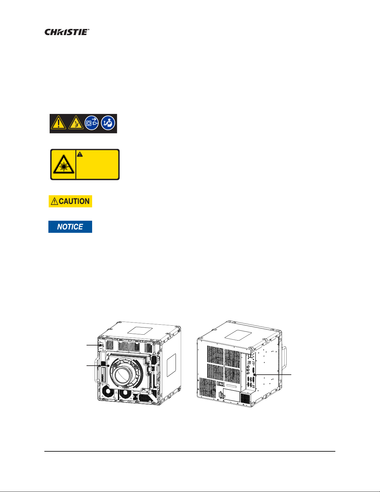
IR remote
sensor
Lens mount
Input panel
Safety Warnings and Cautions
Always power down and disconnect or disengage power before servicing or
cleaning. Failure to comply could result in death or serious injury.
Risk Group 2: Possible hazardous optical radiation emitted from this product.
Do not stare at operating lamp. May be harmful to the eyes. Failure to comply
could result in minor or moderate injury.
Laser radiation is emitted from the laser diode in the remote. Do not look directly into the
laser beam. Failure to comply could result in minor or moderate injury.
Failure to comply with the following may result in equipment damage:
• All installation procedures must be performed by accredited service technicians.
• The projector must be operated in an environment that meets operating specifications, as
listed in Specifications on page 112.
Projector Overview
Mirage WQ-L projectors are professional quality WQXGA data projectors featuring the latest in DLP®
display technology to achieve high brightness, high resolution video projection images. The
modular design of the Mirage WQ-L projectors makes them an ideal choice for the demanding needs
of visualization applications.
Mirage WQ-L User Manual 11
020-101372-01 Rev. 1 (04-2014)

Key Features
i
• Native WQXGA, 2560 x 1600 resolution single-chip DLP® light engine
• Solid-state (LED) illuminator
• Arra yLOC™ feature to maintain uniform color and brightness across multiple projectors
• Display of stereoscopic 3D video
• Two dual-link DVI inputs (digital only)
• Adjustable visible illumination levels
• Warp and blend of projected images
• Operates in any orientation
• Ruggedized for operation on motion platforms
• Compatible with Matrix StIM projection lens suite
• Air-cooled
Introduction
List of Components
A User Kit is supplied with each projection system. Additional User Kits can be purchased
separately (P/N: 130-103105-xx).
Make sure these components were received with the projector:
•Warranty Card
•Web Registration Form
• Line Cord (appropriate for region)
Mirage WQ-L User Manual 12
020-101372-01 Rev. 1 (04-2014)
Installation
i
This section explains how to install, connect and optimize the projector. Illustrations are graphical
representations only and are provided to enhance the understanding of the written material. When
designing a projection room for either a permanent or temporary installation, consider positioning
the projector and screen for maximum audience coverage and space efficiency. For example,
placing the screen along the larger wall in a rectangular room reduces audience coverage.
Other considerations:
• Operating single or multiple units.
• Room size.
• Lighting and audience seating.
• Distance between the audience and the display.
• Angle from which the display is viewed.
Installation Procedures
Unpack the Projector
The projector should be lifted by two people. Use the designated handles to help lift and
support the projector. Use a stable cart to transport the projector. Failure to comply could
result in minor or moderate injury.
Do not place the projector onto a surface with the line cord retainer side down. Failure to
comply may result in damage to the line cord retainer.
Christie recommends that the packaging material for at least one projector is saved in case
one needs to be shipped for service.
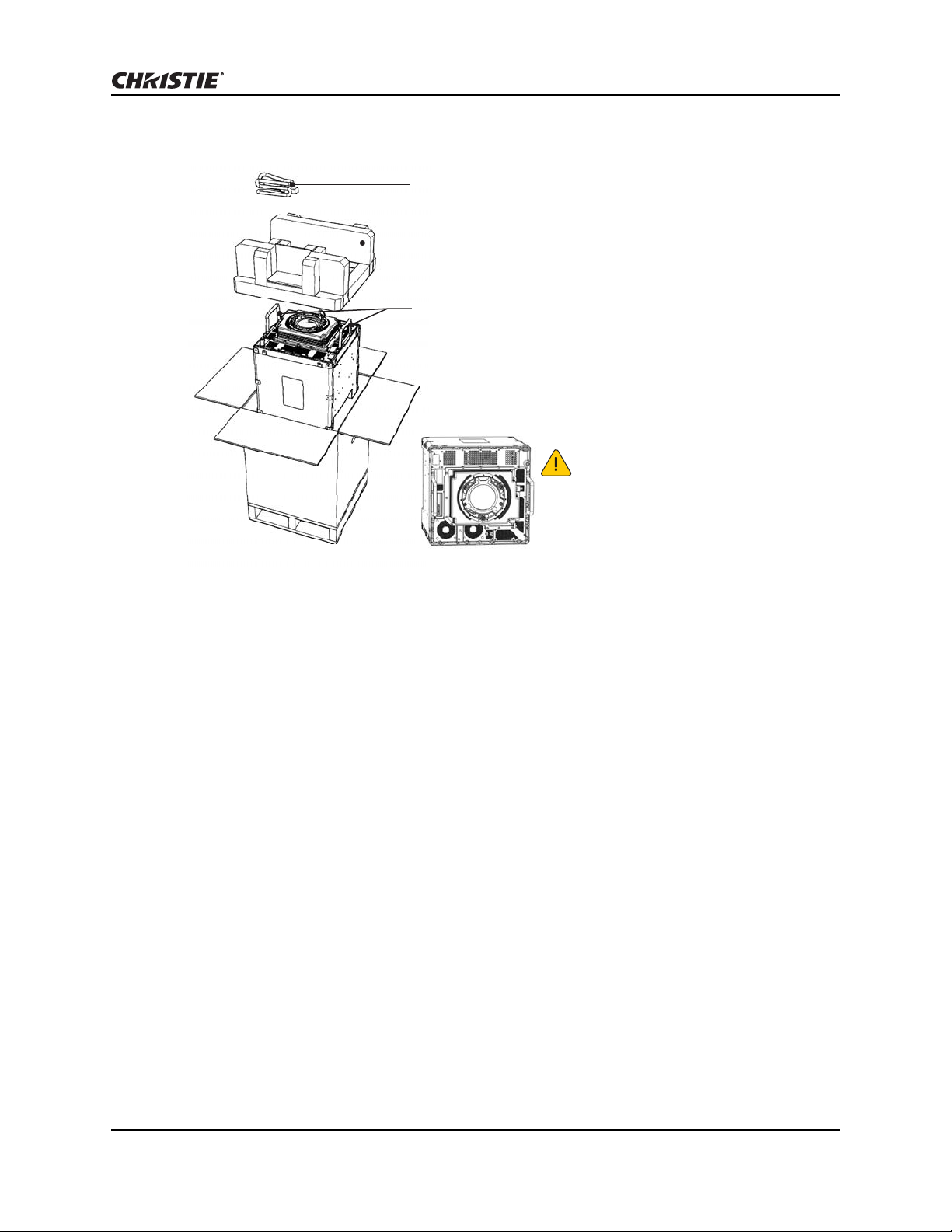
The projector is shipped assembled with the projection lens shipped separately. Install the lens
once the projector is fully assembled and in its final position. See Install the Lens on page 16.
1. Remove the line cord from the packaging.
2. Remove the top foam from the box.
3. Open the bag and lift the projector up using the two handles. It is recommended that two
people remove the projector, each holding onto a handle.
4. Rotate the projector 90° and place on a flat surface.
Mirage WQ-L User Manual 13
020-101372-01 Rev. 1 (04-2014)
Installation
Line cord
Top foam
Handles
Place on a flat surface in the orientation shown.
Do not place the projector onto a surface
with the line cord retainer side down.
Mirage WQ-L User Manual 14
020-101372-01 Rev. 1 (04-2014)
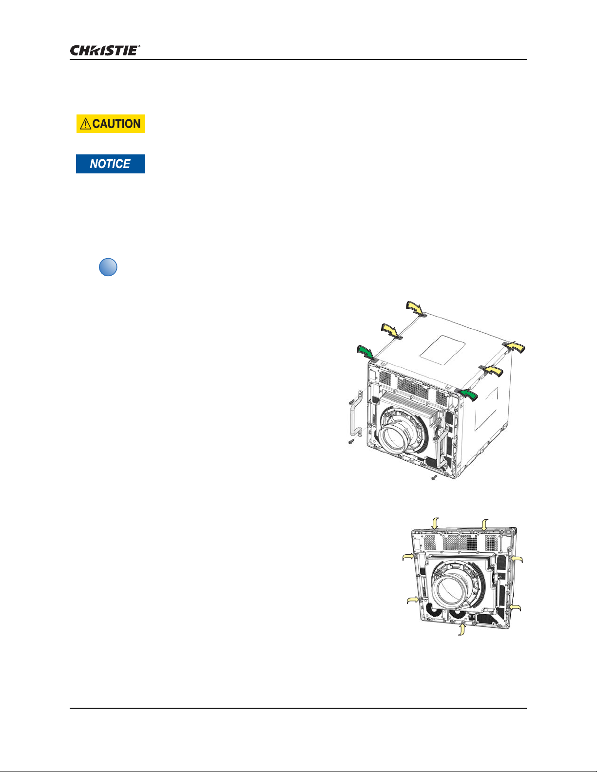
Mount the Projector
i
front plate
mounting point
front plate
mounting point
Do not stack units. Failure to comply could result in minor or moderate injury.
Failure to comply with the following may result in equipment damage:
• Air flows in through the front of the projector and out the rear of the projector.
Insufficient airflow can cause the projector to overhe at during o perati on and / or pl ace
stress on the source connections. When mounting the projector allow for up to 1100
CFM of airflow through the projector. Ambient temperature must stay below 40° C
(95° F).
• Inlet air temperature must be below 40° C (95° F).
• Keep the projector away from all devices radiating electromagnetic energy. For
example, motors and transformers, speakers, power amplifiers, and elevators.
The mounting support system and the mounting surface must be evaluated and
accepted by local authorities and must adhere to local standards and safety regulations.
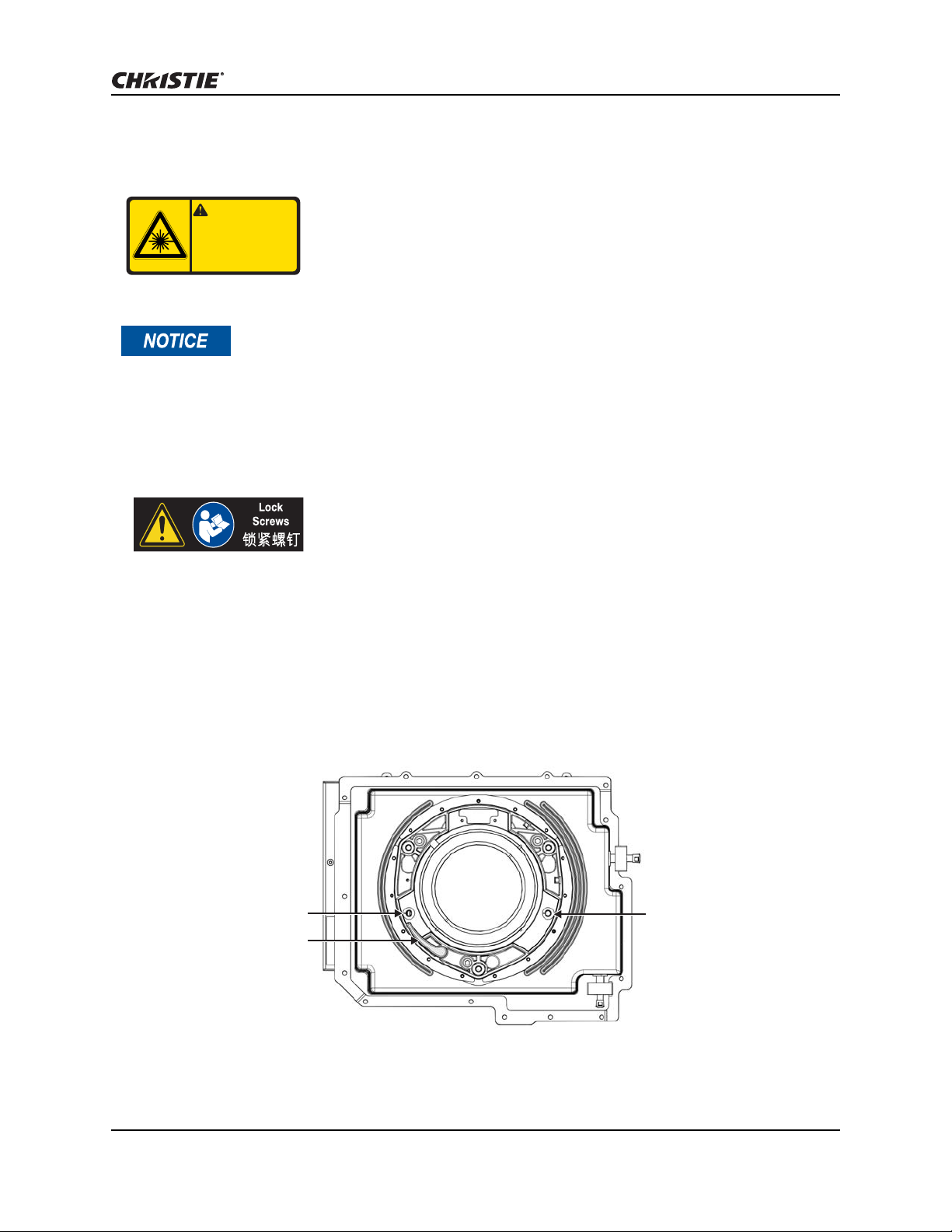
Mounting points are available on all four sides of the
projector, including the front face. Each side has six
mounting points, two of which are on the front
plate. The front plate has an additional seven front
facing mounting points. Christie recommends that a
minimum of four mounting points are used in any
installation, with at least one of the mounting points
being on the front plate. A 10mm thread
engagement and a minimum torque of 30 in.-lbs
(3.5 Nm) /maximum torque of 35 in.-lbs (4 Nm) is
recommended. For some installations it may be
necessary to remove the front handles once the
projector is in its final location. To remove the
handles use a 5 mm hex driver to loosen the two
socket head cap screws.
Installation
Mount a Ruggedized Kit (optional)
If you are mounting a ruggedized kit use the seven designated
mounting points on the front of the projector. The handles will need to
be removed to access four of these points. Christie does not provide
the ruggedized kit or the hardware to secure a ruggedized kit. Christie
recommends using M6 hardware with a 10 mm thread engagement,
and a maximum torque of 4 Nm.
Mirage WQ-L User Manual 15
020-101372-01 Rev. 1 (04-2014)
Install the Lens
Do not stare at operating lamp .
May be harmful to the eyes.
Possible hazardous optical ra diation
em itted from this product.
CAUTION/
Risk Group 2/èq³I§ 2
è
q³I§ 2
,§БпэСъqi„I
÷ÿ ÝÆå\-„oˇïý$³¨„<[÷ÿ ÝÆå\-„oˇïý$³¨„<[
Lens clamp
(closed position)
Security screw
Security screw
Failure to comply with the following may result in equipment damage:
• Do not insert the lens at an angle.
• Always replace the lens plug when transporting to protect the optical components.
• Always place the lens cap onto the lens when transporting to avoid scratching the lens.
• Never operate the projector without a lens.
• A small amount of dust or dirt on the lens has minimal effect on image quality. To avoid the
risk of scratching the lens, clean only if ab solutely necessary. See Cleaning the Lens on
page 62.
Installation
Risk Group 2: Possible hazardous optical radiation emitted from this product.
Do not stare at operating lamp. May be harmful to the eyes. Failure to comply
could result in minor or moderate injury.
For some installations security screws are required on the lens.
1. Remove the lens plug from the lens opening.
2. Remove the rear lens cap from the lens.
3. Rotate the lens clamp to the open position.
4. Remove and retain the two security screws from the lens mount.
5. Align the lens interface plate with the lens mount. Fully insert the assembly straight into the
lens mount opening without turning.
6. Rotate the lens clamp to the closed position before fastening the security screws.
Mirage WQ-L User Manual 16
020-101372-01 Rev. 1 (04-2014)
Installation
i
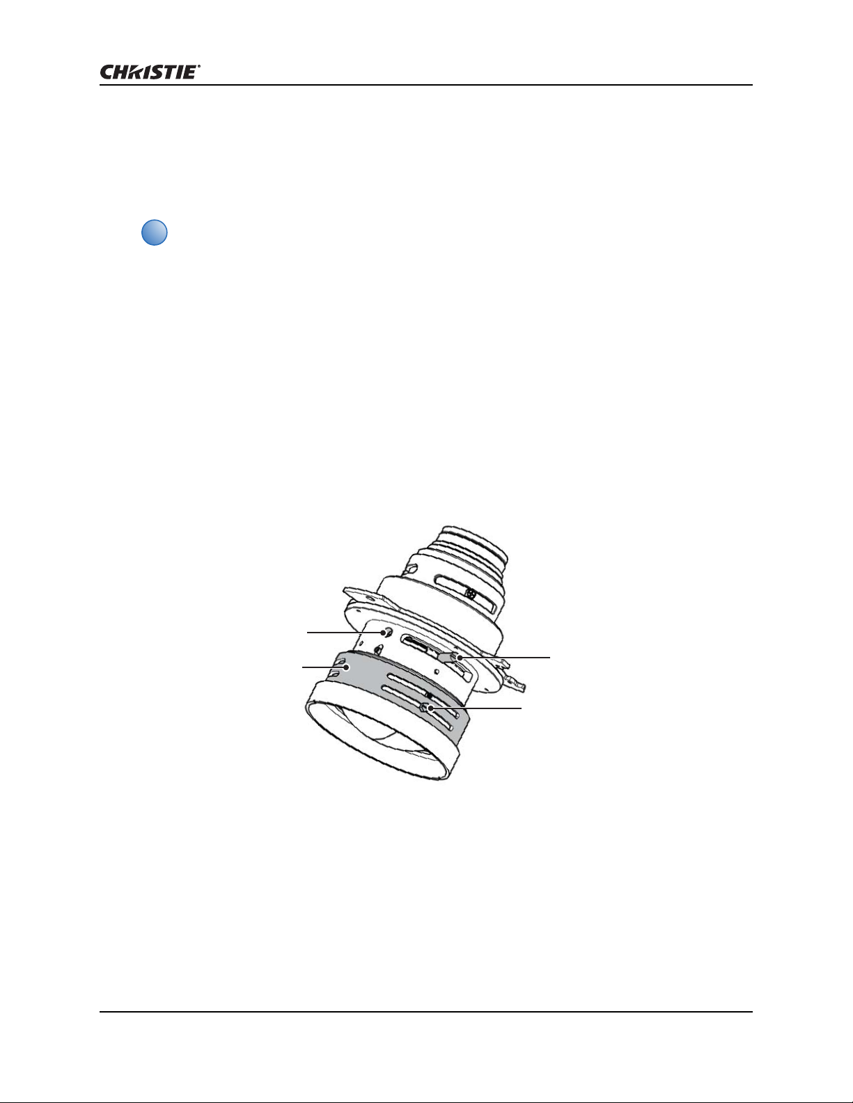
Focusing screw
Locking screw
Field curvature
focusing ring
Field curvature
locking screw
Setup Procedures
Adjust Lens Focus
Failure to properly adjust lens focus results in an image that is not uniformly focused and
contains geometric distortion.
This section describes best practices for lens focus adjustment of the 0.68:1 WQXGA lens
(P/N: 125-103105-xx), the 0.80:1 WQXGA lens (PN: 125-105107-xx), and the 1.28 - 1.71:1
WQXGA lens (P/N: 125-101103-xx).
1. Loosen the locking screw and the focusing screw.
2. Adjust the focusing screw for best focus in the image center.
3. 0.68:1 Lens Only: Loosen the field curvature locking screw and adjust the field curvature
focusing ring to sharpen the image corners.
4. Adjust the focus screw for best overall screen focus.
5. Although it is not necessary, you may want to retighten the main locking screw. Use a
maximum of 4 in.-lbs (0.45 Nm) to tighten.
Calculate Throw Distance and Position
Throw distance is the distance measured from your projector to the screen. This calculation
determines if there is enough room to install your projector with a desired screen size and if the
image size will be the accurate size for your screen. To estimate the throw distance take the
horizontal width of the screen and multiply it by the lens throw ratio. The result determines
approximately the distance the projector should be positioned from the screen to project a focused
Mirage WQ-L User Manual 17
020-101372-01 Rev. 1 (04-2014)

Installation
i
Throw ratio = throw distance ± 2%
screen width
% Offset = # of pixels of offset x 100
half vertical panel resolution
image large enough to fill the screen. For example, using a 1.28 - 1.71 zoom lens set at its widest
(1.2:1) throw ratio, throw distance would roughly be 1.2 x screen width.
Use the lens and screen size to calculate the precis e throw distance. Due to lens
manufacturing tolerances for lens focal length, actual throw distance can vary ±2% between
lenses with the same nominal throw ratio.
Lens Throw
Distance
0.68:1 ±10% ±25% 28 83 0.7 2.1
1.28 – 1.71:1 60% 100% 150% 100% 59 213 1.5 5.4
0.80:1 60% 100% 100% 100% 28 102 0.7 2.6
Offset Percentage
Specified Throw Distance Range
(Offset Pixels)
Horizontal Vertical Inches Meters
left
1
right
1
up down Min. Max. Min. Max.
1. The left and right horizontal offset examples are based on the projector being in the normal
landscape orientation and looking towards the front of the projector from the back (input panel
side).
• Offsets are subject to ±7% centering tolerance.
• Image size outside the specified width range may result in reduced image quality.
• Throw distance is measured from the marked exit pupil position on the lens to the
screen. Throw ratio is defined as:
• 100% offset is defined as having all pixels shifted beyond the projector optical axis.
• Offsets are measured from the optical lens centre, which may not coincide with the
mechanical centre.% offset is defined as:
Determine Vertical and Horizontal Position
The projection lens and the screen type determine the vertical and horizontal position of your
projector in relation to the screen. Ideally, you should position the projector perpendicular to the
screen to make the image appear rectangular instead of keystoned (trapezoidal). You can offset
vertical position of the image (move it above or below the optical axis) by adjusting the lens mount.
The type of projection lens you install determines the amount of available vertical offset. Vertical
offset can be expressed as the percent of half the image height or the number of pixels of shift from
lens center.
Mirage WQ-L User Manual 18
020-101372-01 Rev. 1 (04-2014)
Installation
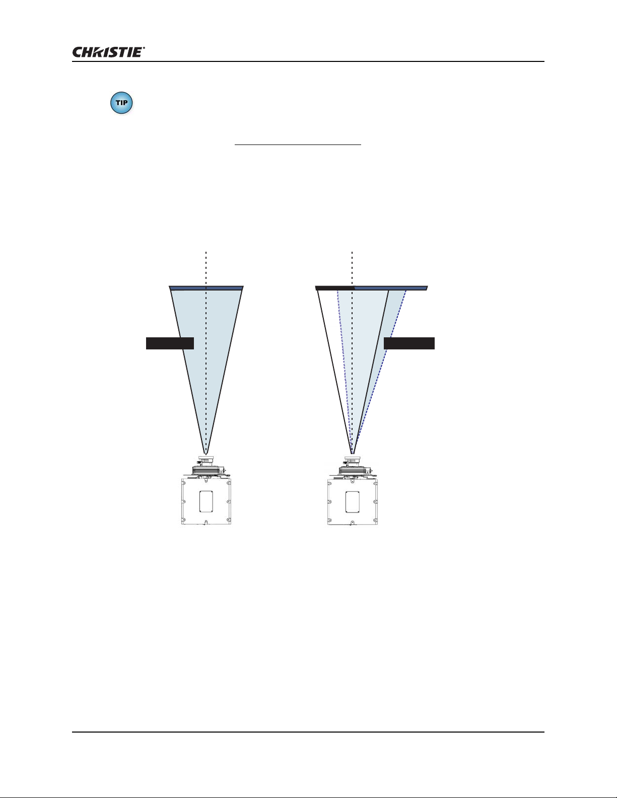
% Offset = # of pixels of offset x 100
half vertical panel resolution
1280 pixels
display to left
of lens center
640 pixels
to left of
lens center
1280 pixels
display to right
of lens center
1920 pixels displayed to
right of lens center or 480 pixels
of shift to the right of lens center
lens center
lens center
0% Offset 50% Offset
Shaded area = projected area
In this example, no offset is applied.
Therefore, half of the image appears to the
left of lens center and half appears to the right.
In this example, 50% offset is applied.
Therefore, 3/4 or 75% of the image
appears to one side of the lens center.
• Offsets are subject to ±7% centering tolerance.
• % offset is defined as:
The horizontal position of the image can also be offset (moved to the left or right of the optical
center) by adjusting the lens mount. The amount of horizontal offset available depends on the lens
installed and if the image has already been vertically offset. Horizontal offset can be expressed as
the percent of half the image width or the number of pixels of shift to one side of lens center.
Connect a Source
All source connections are made to the input panel, located at the back of the projector. Each input
is labeled for easy identification. Using the correct cable(s), connect your source. See Network
Setup for External Communications on page 22.
Mirage WQ-L User Manual 19
020-101372-01 Rev. 1 (04-2014)
Installation
i
i
Status
Remote
P
S
S
F
F
A
B
C
Input 1
Input 2
RS232 IN
RS232 OUT
RS422
ArrayLOC
Network
GPIO
Control
Network
S
F
Serial Port Connections
Use the RS422 port only if the device being used has this capability. Always consult with
equipment literature before connecting.
RS232 and RS422 serial ports are both available on the projector. You can connect a device with a
serial interface, such as a computer to either of these connectors (not both) and control the
projector remotely by entering specific serial communication commands. See Communications on
page 50 and Serial Communication on page 63.
Two nine-pin D-sub connectors, labeled RS232 IN and RS232 OUT on the input panel, are dedicated
to serial communication. Using the appropriate serial communication cables, connect the controlling
source, such as a personal computer to the RS232 IN connector. Set the projector baud rate to
match that of the computer. See Serial Options on page 50.
To control the projector with a computer or other controlling device with RS422 capability, connect
a RS422 serial communication cable between the controlling device and the RS422 port on the
projector. RS422 is better suited than RS232, for serial communication over distances greater than
50 feet (15 m). See RS422 Port on page 63.
Control Network
For further information about setting up and using a projector connected via Ethernet see Configure
the Display on page 48 and Serial Communication on page 63.
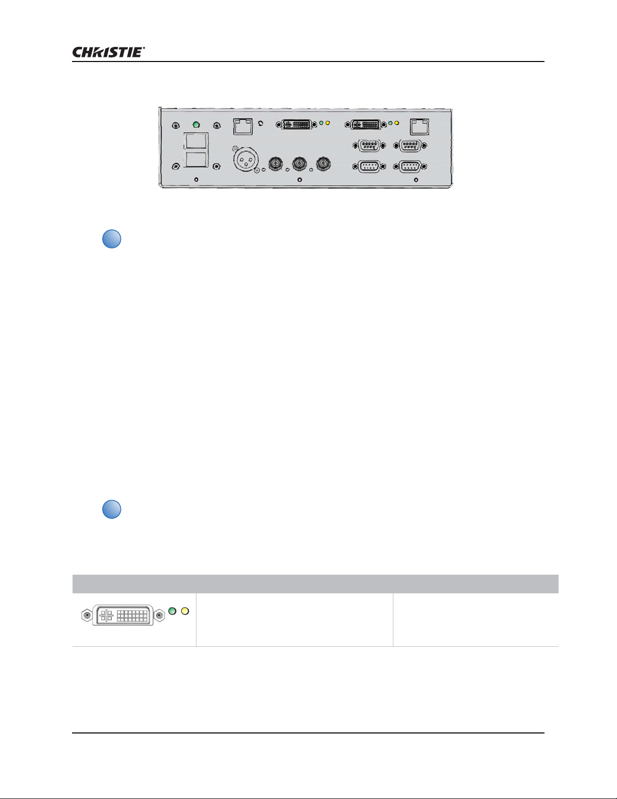
Inputs 1 and 2
Native WQ is required in order to receive a valid DVI-D signal.
Use Inputs 1 and 2 to connect the main and secondary input sources. See Select Inputs on page 41.
The LEDs assigned to each input indicate the following:
S indicator (signal) F indicator (function)
Green: Indicates valid DVI-D source signal.
Red: Indicates an invalid source signal. Check
the connection and make sure the source is
correct.
Off: Indicates no signal detected on DVI port.
Green: Indicates the input is selected.
Yellow: Indicates which of the two
inputs is being used as the secondary
input.
Off: Indicates no input is selected.
GPIO
The GPIO connector provides a method of interfacing a wide range of external I/O devices. For
complete details on pin configuration and how to program the GPIO see GPIO Port on page 108.
Mirage WQ-L User Manual 20
020-101372-01 Rev. 1 (04-2014)
Installation
i
013-102318-01 REV 02
ArrayLOC Network
The ArrayLOC Network connector provides a method of interfacing multiple projectors in an arr ay to
manage preliminary color setup. For details, see ArrayLOC Network Configuration on page 25 and
ArrayLOC on page 41.
Connect to Power
Always power down and disconnect/disengage power before servicing or cleaning
Failure to comply could result in death or serious injury.
Do not operate if the AC supply and cord are not within the specified voltage and power
range. The North American rated line cord is supplied with this projector. For all other
regions, use only a regionally approved line cord, power plug and socket. Do not use a
damaged line cord. Failure to comply could result in death or serious injury.
In Norway, for IT power distribution systems, a dedicated protected earth wire must be
installed on the projector before it can be connected to power. The dedicated earth wire
must be installed by a Christie accredited service technician. To connect the projector to an
IT power distribution system connect the building ground to the internal ground lug behind
the AC input inside the projector. It is recommended that you run the connection through
the louvers on the projector. Failure to comply may result in equipment damage.
The appropriate regional line cords are shipped separately.
1. Connect an approved line cord to the projector AC receptacle. Make sure the security clip is
latched onto the cord.
2. Connect the three-pronged end of the line cord to a grounded AC outlet. The outlet must be
near the equipment and easily accessible.
3. Flip the power switch on the back of the projector. The projector takes approximately two
minutes to initialize. The status light on the input panel turns yellow.
4. Power on the device.
• Press Power, and then the up arrow from the IR remote.
• From the WebUI select Power > On from the Main tab.
5. Press an input key on the IR remote to select and display the image for the connected source.
Disconnect Power
Do not flip the main Power switch to the Off position, or disconnect the projector until the
cooling fans have stopped. Failure to comply may result in equipment damage.
1. Power off the device.
• Press Power, and then the down arrow from the IR remote.
• From the WebUI select Power > Off from the Main tab.
Mirage WQ-L User Manual 21
020-101372-01 Rev. 1 (04-2014)
Installation
i
i
Ethernet Hub
CAT5
CAT5
CAT5
CAT5
to other
Ethernet devices
2. After the internal cooling fans stop, flip the main power switch to the Off position.
3. Disconnect the line cord from the wall outlet.
Network Setup for External Communications
To complete the projector network setup you will also need to connect the projectors
together for ArrayLOC communication and functions. See ArrayLOC Network Configuration
on page 25.
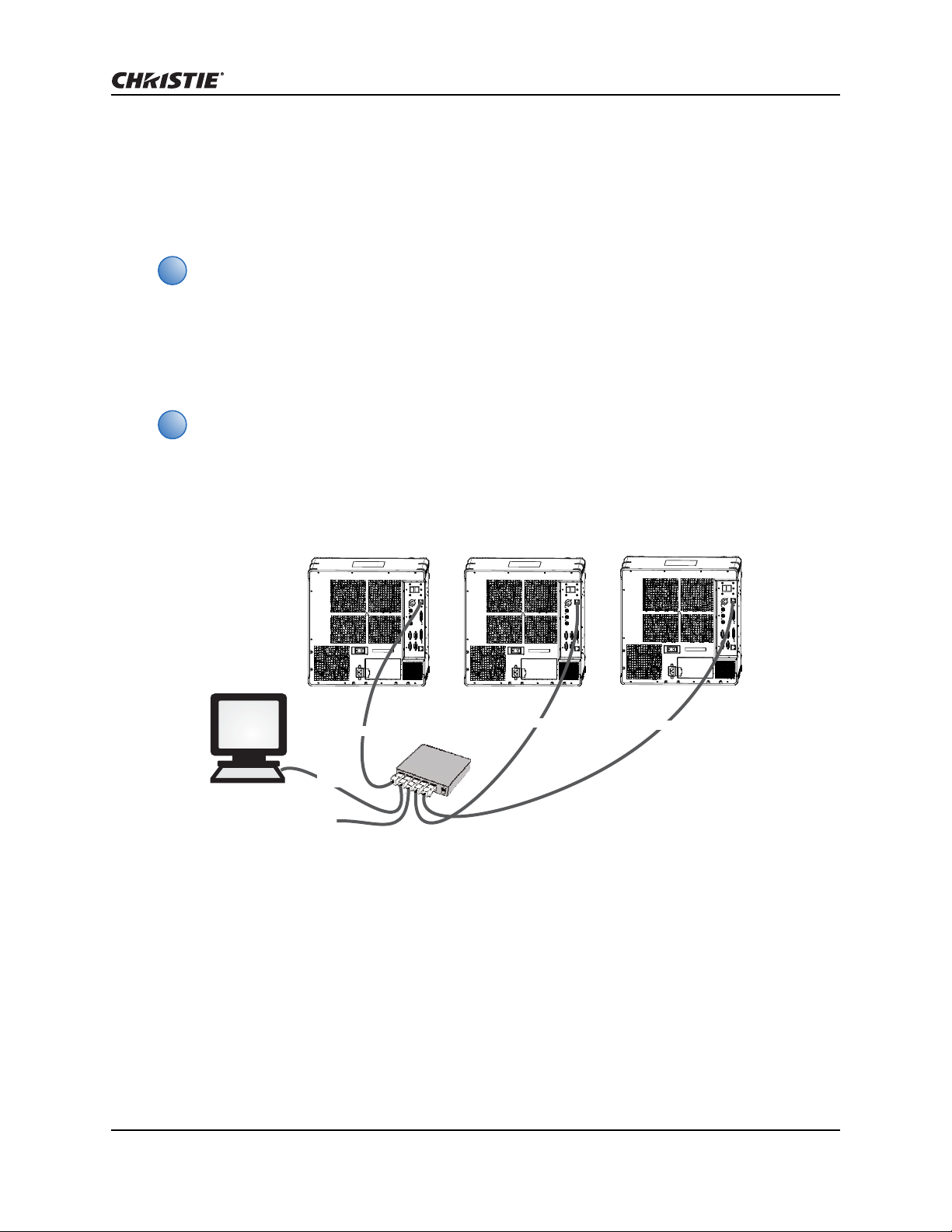
Ethernet (recommended)
In the Ethernet network the controller communicates with each projector separately.
Recommended for network administrators only.
1. Connect a standard CAT5 Ethernet cable between the controller (or Ethernet hub) and the
Control Network port on the projectors input panel.
2. From the WebUI, set the IP address in Configuration > Communications > Ethernet
Settings. See Communications on page 50.
3. From the WebUI, in Configuration > Communications set network routing to Separate. See
Communications on page 50.
Mirage WQ-L User Manual 22
020-101372-01 Rev. 1 (04-2014)
Installation
Ethernet Hub
Projector #1
Projector #2
Projector #3
RS422
CAT5
CAT5
RS232 RS232
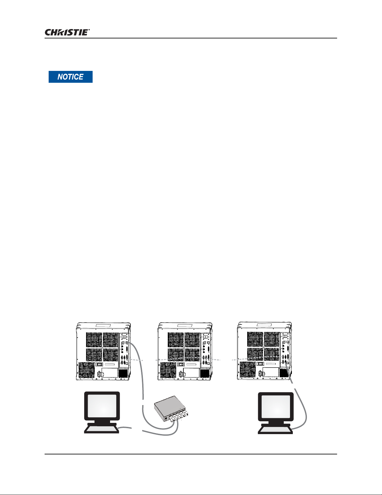
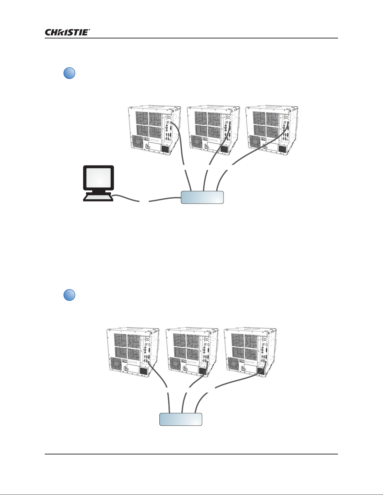
Mixed Network
Using the wrong type of serial cable can damage the projector . RS232 communication cables
must be of good quality and no more than 25 ft (7.62 m) in length. Failure to comply may
result in equipment damage.
In a mixed network the controller can communicate with the first projector and the command can
be relayed to each serially connected projector. This configuration is useful if you are using a
non-RS232 controller with the RS232 linking available between these p rojectors. The image below
shows both an RS422 compatible controller and an Ethernet-connected PC working with a network
of projectors linked using their RS232 in/out ports.
1. Connect the controller to a projector with a standard CAT5 Ethernet cable between the
controller (or Ethernet hub) and the Control Network port on the projectors input panel.
2. Connect an RS422 serial cable between the PC and the RS422 port on the projectors input
panel.
3. Connect a serial cable between the RS232 OUT connector of the first projector and the RS232
IN connector of the next projector.
4. Connect the remaining projectors.
5. If the controller is connected via an Ethernet cable, set the IP address from the WebUI in
Configuration > Communications > Ethernet Settings. See Ethernet Settings on page 51.
6. Set the serial options in Configuration > Communications. See Communications on page
50.
7. From the WebUI, select Configuration > Communications > Network Routing.
• To relay commands to all projectors set Network Routing to All Joined.
• To isolate RS4 22 communications, select RS232 and Ethernet Joined. Only projector
#3 will respond to the RS422 controller.
• To isolate Ethernet communications, select RS232 and RS422 Joined. Only projector
#1 will respond using Ethernet
.
Mirage WQ-L User Manual 23
020-101372-01 Rev. 1 (04-2014)

Installation
RS232 IN
RS232 OUT RS232 OUT
RS232 IN RS232 IN
RS232 IN
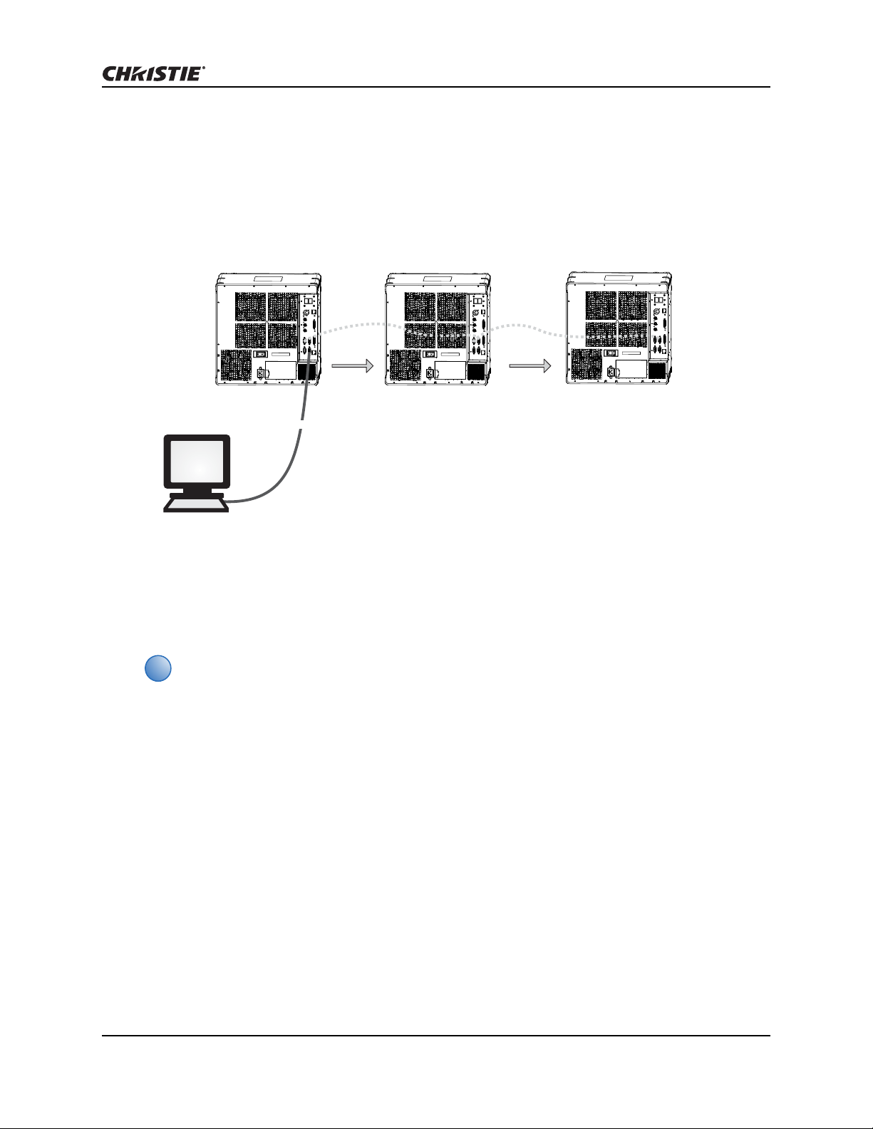
RS232 Network
Using the wrong type of serial cable can damage the projector . RS232 communication cables
must be of good quality and no more than 25 ft (7.62 m) in length. Failure to comply may
result in equipment damage.
In an RS232 network the controller can communicate with the first projector and the command can
be relayed to each serially connected projector.
1. Connect the controller to one projector by connecting a serial cable between the PC and the
RS232 IN port on the input panel.
2. Connect a serial cable between the RS232 OUT connector of the first projector and the RS232
IN connector of the next projector.
3. Connect the remaining projectors.
4. Set the RS232 serial options in Configuration > Communications > Serial (RS232 IN)
Options. See Communications on page 50.
5. Set network routing in Configuration > Communications > Network Routing to RS232
and RS422 Joined. See Network Routing on page 50.
Mixed Serial Network (RS232 and RS422)
Do not connect incompatible equipment, including th e wrong type of serial cable to the
RS422 port. Failure to comply could cause equipment damage.
RS422 serial communication is better over long distances than RS232 communication. Use the
RS422 port only if your device has RS422 capability. Always read the equipment literature before
connecting. In the RS422 network the controller can communicate with the first projector and the
command can be relayed to each serially connected projector.
1. Connect the controller to one projector by connecting an RS422 serial cable between the PC
and the RS422 port on the input panel.
Mirage WQ-L User Manual 24
020-101372-01 Rev. 1 (04-2014)
Installation
i
RS422
RS232 OUT RS232 OUT
RS232 IN RS232 IN
RS232 IN
2. Connect an RS232 serial cable between the RS232 OUT connector of the first projector and the
RS232 IN connector of the next projector. Connect the remaining projectors using RS232
cables.
3. Set the serial options in Configuration > Communications. See Communications on page
50.
4. Set network routing in Configuration > Communications > Network Routing to RS232
and RS422 Joined. See Network Routing on page 50.
ArrayLOC Network Configuration
Preliminary color setup is managed by ArrayLOC. ArrayLOC is enabled by default and configured to
display a reasonably saturated gamut at the maximum brightness that all the projectors in the
array can support. See Configure the Display on page 48 for detailed information.
A projector that is not connected via ArrayLOC functions as a single unit array.
ArrayLOC over Control Network
Use the Control Network for ArrayLOC when you want to communicate with the projectors in the
array over the same network.
1. Connect the controller by connecting a CAT5 Ethernet cable between the PC and the ArrayLOC
network switch.
2. Connect a standard CAT5 Ethernet cable between the Arr ayLOC network switch and the C ontrol
Network port of each projector.
3. From the Main menu, select ArrayLOC > ArrayLOC Configuration.
4. From the ArrayLOC Network drop-down list select Control Network.
Mirage WQ-L User Manual 25
020-101372-01 Rev. 1 (04-2014)
Installation
i
i
ArrayLOC
Network Switch
CAT5
CAT5 CAT5 CAT5
CAT5
CAT5 CAT5 CAT5
ArrayLOC
Network Switch
CAT5 CAT5CAT5CAT5 CAT5CAT5
The length of the connections depends on ArrayLOC network switch placement within the
array. It may be possible to reuse the Ethernet cable supplied with the projector for one of
these connections, but at least one connection requires that you supply an additional
Ethernet cable per projector.
ArrayLOC over ArrayLOC Network (preferred)
The ArrayLOC Network should be used if you want to isolate the ArrayLoc network traffic from the
Control Network.
1. Connect a standard CAT5 Ethernet cable between the ArrayLOC network switch and the
ArayLOC Network port on the projectors input panel.
2. From the Main menu, select ArrayLOC > ArrayLOC Configuration.
3. From the ArrayLOC Network drop-down list select ArrayLOC Network.
The length of the connections depends on ArrayLOC network switch placement within the
array. It may be possible to reuse the Ethernet cable supplied with the projector for one of
these connections, but at least one connection requires that you supply an additional
Ethernet cable per projector.
Mirage WQ-L User Manual 26
020-101372-01 Rev. 1 (04-2014)

Installation
i
Adjust Image Geometry and Optical Alignment
This initial optical alignment is the foundation for optimizing images on the sc reen, and must
be completed before final boresight adjustments. Only perform image alignment once the
projector is fully assembled and powered up in its final location.
Basic Optical Alignment
1. Press Test on the IR remote to display a test pattern.
It is recommended to use the Edge Blend or Grid test pattern.
2. Perform a quick preliminary focus and (if available) z oom adjustment with the primary lens. Do
not worry about consistency across the image at this point, just center focus. It is good practice
to have the zoom adjustment collar and the focus adjustment collar in the center of its range.
3. Hold a piece of paper at the lens surface, adjust offsets as necessary until the image is centered
within the lens perimeter. A full white field works best for this.
4. If necessary, center the image on the screen. If the projector is mounted off-center to the
screen axis, then offset the lens as much as required. Aim the projector over slightly towards
the center of the screen, but use caution, as too much tilt will cause excessive keystone
distortion. Lens offset will not.
5. With the test pattern on screen, double-check projector leveling so the top edge of the image is
parallel to the top edge of the screen. Make sure the projector is positioned in the throw
distance range for the lens in use.
Folded Optics
In rear screen applications where space behind the projector is limited, a mirror may be used to
fold the optical path. The position of the projector and mirror must be accurately set — if
considering this type of installation contact Christie Customer Support for assistance.
Mirage WQ-L User Manual 27
020-101372-01 Rev. 1 (04-2014)
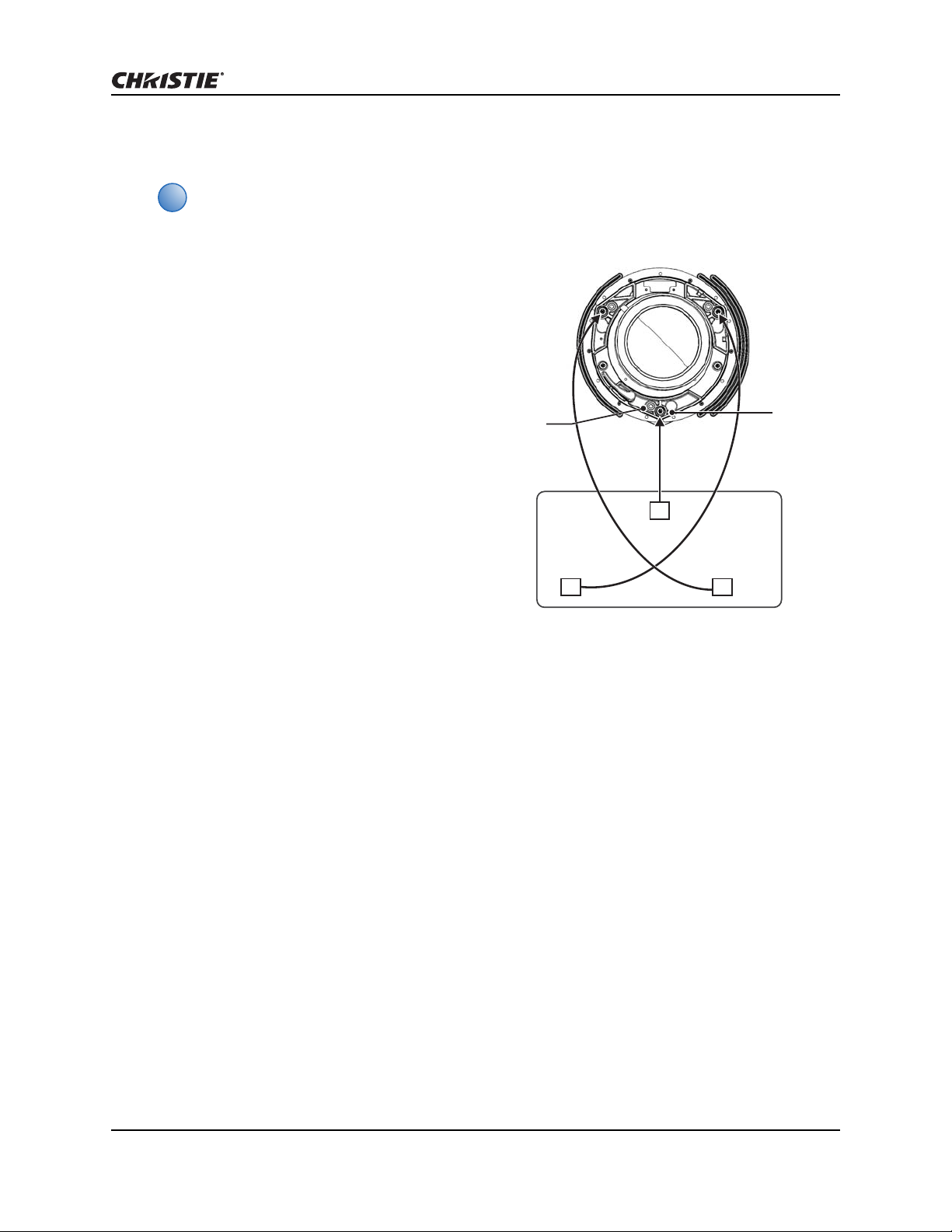
Boresight Alignment
i
3
12
Capscrew
Setscrew
• Boresight alignment is an adv anced feature and should only be performed by experienced
users.
• You can also use the Grid or Edge blend test pattern to perform boresight alignment.
1. Display the Boresight test pattern by
pressing Test on the IR remote and use the
Left arrow key to cycle to Boresight.
2. Adjust the lens focusing ring until each
square displayed in the Boresight test
pattern is focused. If all three squares are
in focus, no further action is required.
3. If boresight is required, see the image on
the right to understand how the adjustment
screws on the lens mount affect the
corresponding squares on the test pattern.
4. Use a 5 mm hex key to loosen the three
locking set screws on the lens mount. The
set screws must be backed out several
turns, so that they do not contact the inner
lens mount plate.
Installation
5. Fine tune the focus of square one, by
adjusting the appropriate cap screw. Adjust until the image is in focus with minimal flare.
6. Adjust square 2, by adjusting the appropriate cap screw. Adjust until the image is in focus with
minimal flare.
7. Adjust square 3, by adjusting the appropriate cap screw. Adjust until the image is in focus with
minimal flare.
8. Repeat steps 5 to 7, as required until all squares on the test pattern are equally focused. If the
boresight is acceptable, continue to step 11. If the boresight does not appear to be converging
to an acceptable level of image quality or if the lens will not focus over the correct range of
throw distances, then the boresight requires coarse adjustment. See step 9.
9. The original factory boresight can be recovered approximately by positioning the three set
screws. Position the set screws flush with the front face of the lens mount plate and in contact
with the inner lens mount plate. This may require adjusting both set screws and cap screws.
10. If further action is required, repeat step 2.
11. Lock the set screws, and re-check the boresight quality . Tighten the set screws to prevent them
from shifting.
12. When the image is focused, lock adjustments in place by tightening the adjustment screws until
just tight.
Mirage WQ-L User Manual 28
020-101372-01 Rev. 1 (04-2014)

Installation
i
Adjust Software to Optimize Image
Unless otherwise indicated, instructions apply to all projector models in stand-alone or
multi-projector configurations.
1. Display an external signal.
2. Select Screen Image Orientation in Configuration > Output Options and change the
orientation of the displayed image to suit the installation.
3. Assign projector ID number(s).
See Projector Address on page 50.
4. Make sure that ArrayLOC is enabled. From the Main menu select ArrayLOC and select Enabled
from the Bright/ColorLOC Mode drop-down list. ArrayLOC automatically adjusts projector
colors and brightness.
5. Adjust ArrayLOC color target.
See Adjust Projected White and Primary Colors for the Array on page 43
6. Fine-tune ArrayLOC to compensate for system optics.
See Fine-tune Projector Colors with a Color Meter on page 46.
Mirage WQ-L User Manual 29
020-101372-01 Rev. 1 (04-2014)
Web UI Overview
i
7
8
9
10
2
1
5
3
4
11
6
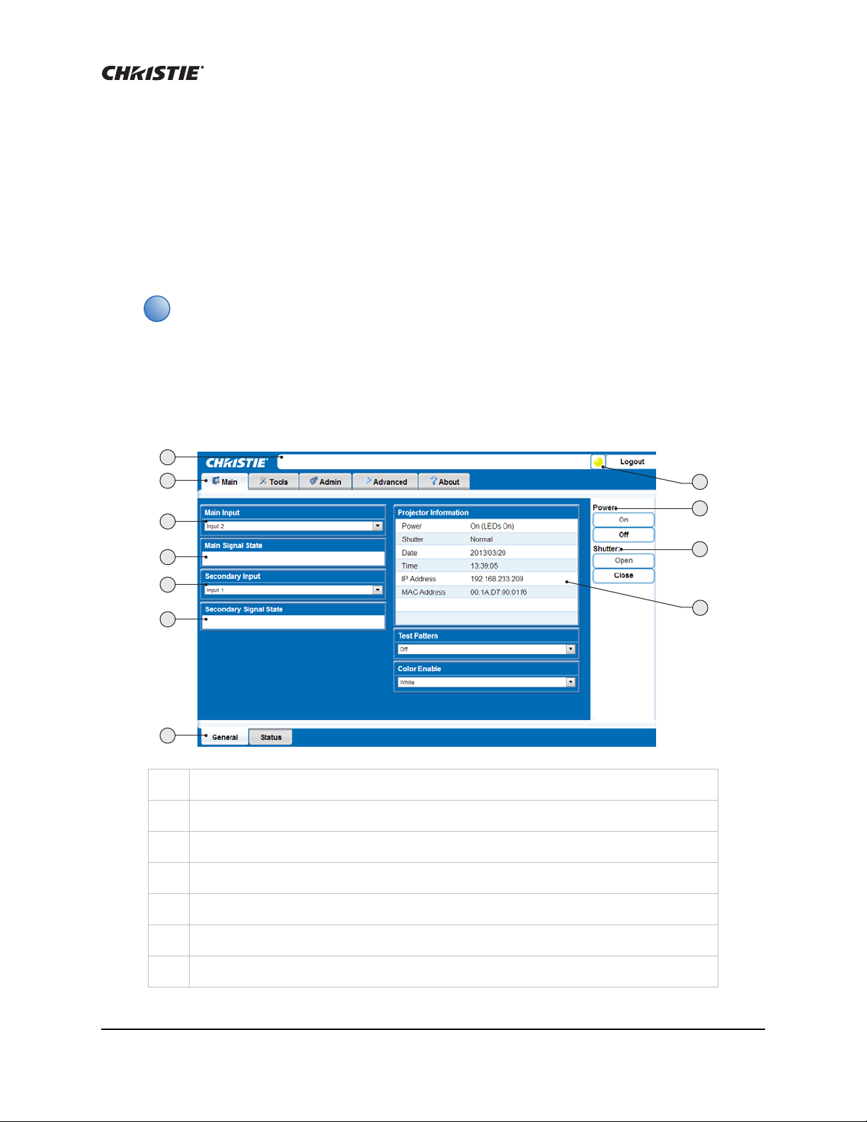
Login to WebUI
1. Open your web browser and enter the IP address (in the address bar) assigned to your
projector.
The factory default IP address is 192.168.1.89. To change the default use the NET serial
command through RS232. See Network Setup (NET) on page 90.
2. Select the appropriate language from the Language drop-down list, located in the upper lefthand corner.
3. Enter your user name and password. Both entries are case-sensitive.
4. Click the Login button. The Main window appears.
Status bar
1
Primary tabs
2
Main Input drop-down list
3
Main Signal State (read-only)
4
Secondary Input drop-down lists
5
Secondary Signal State (read-only)
6
Secondary tabs (specific to a primary tab) located along the bottom of the Main page.
7
Mirage WQ-L User Manual 30
020-101372-01 Rev. 1 (04-2014)
 Loading...