

Christie Roadster S+, Mirage S+ User Manual

Roadster/Mirage S+ User's Manual
Table of Contents
Section Contents Page
1
Installation &
2
Basic
3
Introduction
Setup
Operation
Maintenance
4
Troubleshooting
5
6
Specifications
1.1 The Projectors...................................................................................................1-1
1.2 Components......................................................................................................1-2
1.3 Purchase Record and Warranty Registration....................................................1-3
2.1 Quick Setup ......................................................................................................2-1
2.2 Installation Considerations ...............................................................................2-3
2.3 Projector Position and Mounting....................................................................2-15
2.4 Source Connections ........................................................................................2-18
2.5 Connecting Communications..........................................................................2-21
2.6 Connecting Multiple Projectors......................................................................2-24
2.7 Power Connection .......................................................................................... 2-27
2.8 Operating Orientation .....................................................................................2-28
2.9 Leveling..........................................................................................................2-28
2.10 Zoom, Focus, and Lens Offset........................................................................2-29
2.11 Keypad Protocols and Conversion .................................................................2-29
3.1 Overview ..........................................................................................................3-1
3.2 Projector Basics ................................................................................................3-1
3.3 Using the Keypads............................................................................................3-4
3.4 Navigating the Menus.....................................................................................3-12
3.5 Using Inputs and Channels.............................................................................3-16
3.6 Adjusting the Image........................................................................................3-21
3.7 Adjusting System Parameters and Advanced Controls ..................................3-37
3.8 Working with PIP or Seamless Switching...................................................... 3-51
3.9 Working with the Lamp..................................................................................3-54
3.10 Status Menu ....................................................................................................3-58
3.11 Using Multiple Projectors...............................................................................3-58
3.12 Remote Control of the Projector.....................................................................3-70
3.13 Error Conditions ............................................................................................. 3-71
4.1 Warnings and Guidelines .................................................................................4-1
4.2 Cleaning............................................................................................................4-4
4.3 Replacing Keypad Batteries .............................................................................4-5
4.4 Replacing the Lamp and Filter .........................................................................4-5
4.5 Replacing the Lens .........................................................................................4-11
5.1 Displays ............................................................................................................ 5-1
5.2 Lamp................................................................................................................. 5-3
5.3 Ethernet.............................................................................................................5-4
6.1 Specifications ...................................................................................................6-1
continued…
013-100190-03 (06/06) Software v1.2d Roadster/Mirage S+ User’s Manual i

TABLE OF CONTENTS
Appendices
NOTE: Due to continuing research, all information in this manual is subject to change without notice.
A Glossary ...........................................................................................................A-1
B Remote Keypad ...............................................................................................B-1
C Serial Communication Cables..........................................................................C-1
D Throw Distance................................................................................................D-1
E System Integration ........................................................................................... E-1
F Optional Input Modules................................................................................... F-1
ii
Roadster/Mirage S+ User’s Manual 013-100190-03 (06/06) Software v1.2d
1.1 The Projectors
Section 1
Introduction
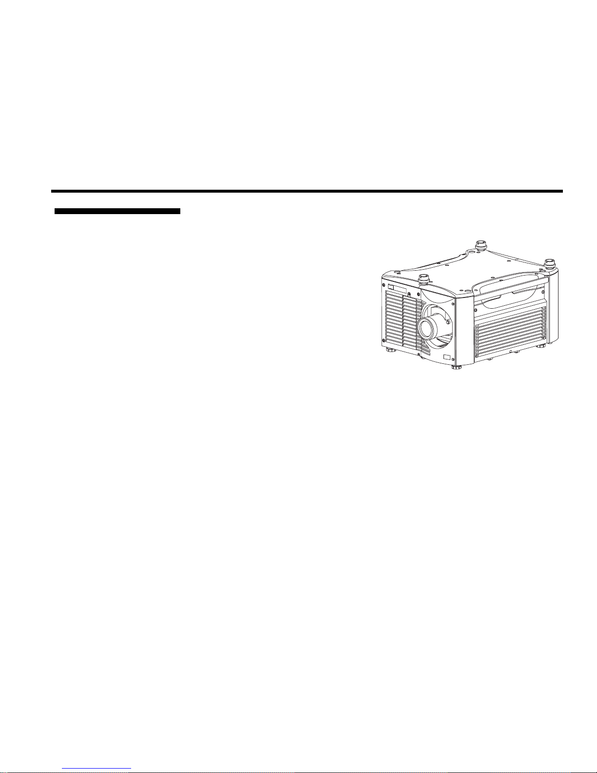
The Roadster S+ and Mirage S+14K projectors are innovative, high brightness
DMD™ projectors that use next generation Digital Light Processing™ (DLP™)
technology from Texas Instruments. All
models feature compact size, rugged
construction, and integral rigging
hardware, with the Roadster Series ideal
for difficult rental/staging installations of
multiple projectors, and the Mirage S
Series featuring amazing stereo 3D
output. A quick-change lamp module,
no-tool lens replacement, and intuitive
user interface means the ultimate in
versatility and ease-of-use. These
projectors provide brilliant images with
1400 x 1050 clarity and perfect color
saturation in a wide variety of applications.
The Roadster S
+
Series and Mirage S+ Series each have features for your distinct
needs. The stereoscopic Mirage S+ projector provides 3D solutions for power walls,
simulation, and entertainment venues. Roadster models include an additional input
module as well as integral hardware for stacking and flying up to 3 projectors.
+
+
Roadster S
Series
Main Features h
General
DLP™ 3-chip electronics with true 1400 x 1050 (SXGA+)
10 bit digital video processing
Single-lens design with field-interchangeable, fast-change lens – no tools needed
Modular design for easy servicing
Intelligent Lens System (ILS
Built-in handles and multiple rigging points
Lenses
) to save and restore lens positions
Choice of lenses (from 0.73:1 up to 7.3:1), all zoom lenses motorized
Lamps / Light Output
Brightness (ANSI lumens)
Roadster S
Roadster S
Roadster S
Contrast Ratio (ANSI lumens)
Roadster S
Roadster S
LiteLOC™ for automatic constant-brightness control
Roadster/Mirage S+ User’s Manual 1-1
+
12K = 12000 (± 10%)
+
16K or Mirage S+ 14K = 16000 (± 10%)
+
20K = 20000 (± 10%)
+
12K/16K or Mirage S+ 14K = 450-600:1, 1500-1800:1 Full Field
+
20K = 450:1 ANSI, 1500:1 Full Field

INTRODUCTION
Quick change bubble-style lamp module
Inputs
One analog RGBHV/YPbPr input with 5 BNCs
One DVI-I input for either digital RGB/YCrCb or analog RGB/YPbPr signals
One analog composite-video input
One analog S-video input
Built-in multi-standard video decoder (NTSC, NTSC 4.43, PAL, PAL-M, PAL-
N, PAL-60 AND SECAM)
One Dual SD/HD-SDI input (standard in Roadster Series only)
Compatible with all currently used HDTV formats
Special Display Functions
Auto setup with seamless cut-and-fade source switching
Electronic brightness uniformity
Screen-to-screen matching and blending for smooth multiple-projector displays
Communications and Diagnostics
2 standard keypads: built-in and remote (for IR or wired control)
Front and rear IR sensors
Ethernet, RS232, RS422, and GPIO control ports
Easy-view LED for error codes and LCD for status and error messages
Voltmeter for monitoring AC
How The Projectors Work h
1.2 Components
Model Name Lamp
Type
Roadster S+12K
Roadster S+16K
Roadster S+20K
Mirage S+14K
2.0 kW
2.4 kW
3.0 kW
2.4 kW
These projectors accept data/graphics and video input signals for projection on to
front or rear flat screens. High brightness light is generated by an internal Bubble
lamp, and then modulated by three DMD (digital micromirror device) panels that
provide digitized red, green or blue color information. Light from the “on” pixels of
each panel is reflected, converged and then projected to the screen through the front
lens, where all pixels are superimposed as a sharp full-color image.
Make sure you have received the following standard components:
Projector
Infrared (IR) remote keypad and conversion cable
Power cord (NOTE: integral on Roadster S
Roadster/Mirage S
Using 3D in Mirage Manual (NOTE: for Mirage S
3D Stereo Sync Cable (NOTE: for Mirage S
+
User’s Manual
+
20K)
+
Series only
+
Series only)
Differences Between Models
Dual SD/HD-
SDI Module
Optional
3D Adjustable Iris Stacking
Not Available
Not Available
Not Available Not Available
Mounts
4 Top
Eyebolts
Integral Rigging
Optional Optional
Hardware
1-2
Roadster/Mirage S+ User’s Manual

1.3 Purchase
Record and
Warranty
Registration
INTRODUCTION
Whether the projector is under warranty or the warranty has expired, Christie’s
highly trained and extensive factory and dealer service network is always available to
quickly diagnose and correct projector malfunctions. Complete service manuals and
updates are available to service technicians for all projectors.
Should you encounter a problem with the projector and require assistance, contact
your dealer or Christie. In many cases, any necessary servicing can be performed on
site. If you have purchased the projector, fill out the Purchase Record below and keep
with your records. In addition, make sure to complete the Product Registration at the
Christie website—this will ensure that you receive all future product communications
promptly.
Purchase Record
Dealer:
Dealer Phone Number:
Projector Serial Number :
Purchase Date:
Installation Date, if applicable:
NOTE: The projector serial number is located on the projector’s rear identification label
and in the projector’s “Status” menu.
Roadster/Mirage S+ User’s Manual 1-3


Section 2
Installation & Setup
This section explains how to install and set up the projector. If you are familiar with the projector and want to quickly
set it up for temporary use, follow the Quick Setup instructions below. For a more complete setup, follow the
instructions and guides covered in the remaining subsections.
NOTE: The lens is not installed for shipping. Refer to 4.5, Replacing the Lens.
Follow these steps for quick setup of the projector in a standard floor mount position.
2.1 Quick Setup
Use either the remote or built-in keypad to work with the projected image.
STEP 1 '
STEP 2 '
STEP 3 '
Position the Projector
Set the projector at the expected throw distance (projector-to-screen distance) and
vertical position. See 2.3, Projector Position and Mounting and Appendix D. Make
sure that the projector is level from side-to-side (see Section 2.9, Leveling).
Connect a Source
Locate the main input panel at the rear of the projector and connector your source to
the appropriate input:
◊ INPUT 1 (upper right area) – RGB input via BNC connectors.
◊ INPUT 2 (left of BNCs) – digital or analog signals (DVI-I) from a computer.
◊ INPUT 3 (upper middle area) – composite video.
◊ INPUT 4 (upper middle area) – S-video.
◊ INPUT 5 (lower area of Roadster panel) – a factory-installed Dual SD/HD-SDI
module that can accept serial digital.
◊ INPUT 6 (lower area) – for optional input modules (see Appendix F).
Connect to Power
The North American rated line cord is provided with each projector. Ensure
that you are using a line cord that meets the appropriate rating standards (CCC
for use in China, PSE for use in Japan).
Connect the projector’s line cord to the AC receptacle* at the lower rear corner on
the rear of the projector, and to proper AC—note the socket outlet must be installed
near the equipment and is easily accessible. Use only the line cord provided with the
projector. Power requirements are shown below, with complete information in Section 6.
*NOTE: The Roadster S+20K has an integral line cord.
Roadster/Mirage S+ User’s Manual 2-1
INSTALLATION & SETUP
STEP 4 '
◊ The Roadster S+12K requires 200-240 VAC, 50-60 Hz, 12 amps @ 200 VAC.
◊ The Roadster S
+
16K and the Mirage S+14K require 200-240 VAC, 50-60 Hz, 16
amps @ 200 VAC.
+
◊ The Roadster S
20K requires 200-240 VAC, 50-60 Hz, 24 amps @ 200 VAC.
WARNING
Do not attempt operation if the AC supply and cord are not
within the specified voltage and power range. See Section 6.
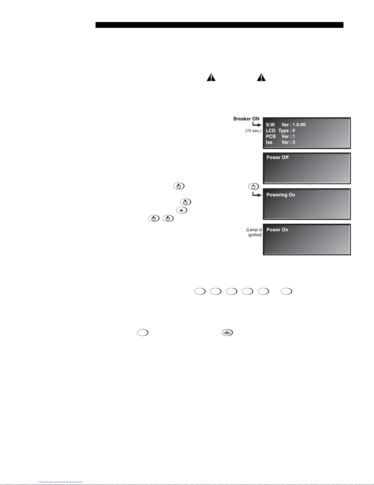
Turn On the Projector and Lamp
1. On the projector, turn the power
breaker/switch on. The LCD Status
Display Window displays the
initializing window for 15 seconds,
then indicates
POWER OFF (see
right).
2. Using the keypad, do one of the
following:
• Press and hold
briefly to
toggle the lamp on.
• Press and release
immediately by
• Press
followed
.
to toggle from the
off state.
The LCD Status Display Window
will display Powering Up and
then, Power On (Figure 2.1) while
the 2 Digit Status/Error Code
Figure 2.1. Turning on the projector
Window will display ON.
STEP 5 '
STEP 6 '
2-2
Roadster/Mirage S+ User’s Manual
Select a Source
Using either keypad, press
,
,
,
Input 5
,
, or
Input 6
to select and display
Input 1
Input 2
Input 3
Input 4
the image for the source you connected in Step 2. The display will resize as needed,
producing an image as large as possible for the type of source present.
Optimize the Display
Press
on the built-in keypad (or
on the remote keypad) to initiate an
Aut o
Set u p
automated process in which the projector optimizes critical display parameters such as
size, position, pixel tracking, etc., for the current source. Auto Setup can save time in
perfecting a display, and you can modify the adjustments later as desired. See Section 3.
STEP 7 '
p
g
INSTALLATION & SETUP
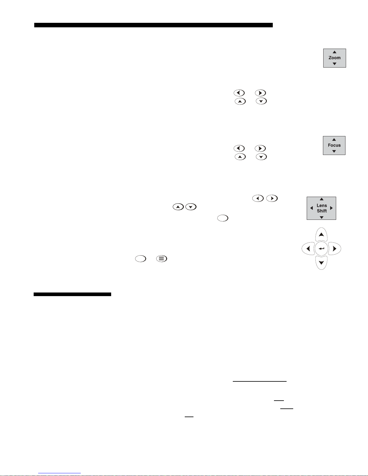
Lens Adjustments
NOTE: Not applicable to fixed lenses. Focus fixed lens by turning focus
ring on lens.
•
ZOOM: With the input image displayed:
.
o If remote keypad: Press Zoom
o If built-in keypad: Press Zoom
or
or
.
Hold the key down to see the effect –arrows in the display indicate the direction
of the zoom (Figure 2.2).
•
FOCUS: With the input image displayed:
.
o If remote keypad: Press Focus
o If built-in keypad: Press Focus
or
or .
Hold the key down to see the effect – arrows in the display indicate
the direction of the focus (Figure 2.3).
•
• LENS OFFSET: To move the image:
o
If remote keypad: Press either Lens H
Lens V
o If built-in keypad: Press
(Figure 2.4).
Lens
Sh if t
keys.
and use the arrow
or
Figure
2.2
Figure
2.3
Ste
2.2 Installation
Considerations
Lifting, Hoisting, '
and Stackin
8 '
Image Adjustments
Menu
Press
or
(remote) to access display parameters
described in Section 3.
.
Figure 2.4
Although this projector delivers a high brightness, quality output, final display
quality could be compromised if the projector is not properly installed. This
subsection discusses issues you should consider before proceeding with a final
installation. Even if you do not intend to use the projectors in a fixed and permanent
installation, the following information will help you to better understand what you
can do to enhance display performance
For any new installation, you will likely have to safely lift or hoist the projector into
place. Keep in mind the following guidelines for safety.
Lifting
All models include handles for convenient hand transport only
, such as when a
projector is lifted from a shipping container to a table. Note the following:
◊ The handles are intended to support the weight of one
◊ The handles are intended to support a projector for a brief
◊ The handles are not
safety points, nor points from which to hoist or suspend
projector only.
time only.
the projector.
Roadster/Mirage S+ User’s Manual 2-3
INSTALLATION & SETUP
WARNINGS
• The handles can’t support more than 1 projector.
• Do not
• Do not
from which to suspend or hoist the projector.
use handles for extended time periods.
use the handles as safety points, or as points
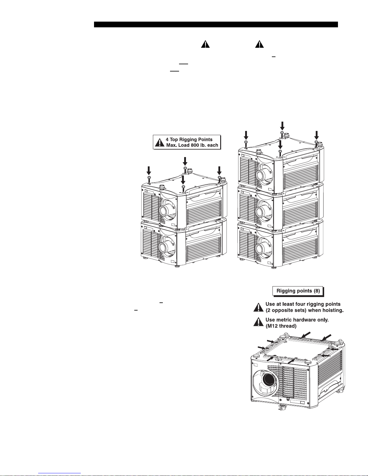
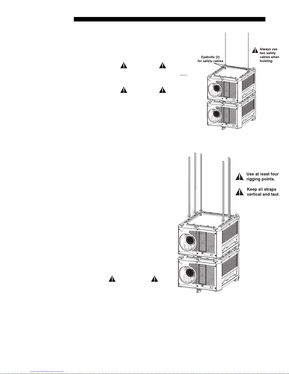
Hoisting
Four integral rigging points on the top of the projector (Figure 2.5) and eight on the
bottom (Figure 2.6) enable either upright or inverted hoisting. For either orientation,
hoist an individual projector, or up to 3 projectors in a stack.
Figure 2.5. Top Rigging Points
RULES FOR ALL HOISTING:
◊ Use at least 4 rigging points for hoisting up
projectors.
to 3
◊ Connect safety cables, and rigging
equipment to the designated locations on
the projector.
◊ Use hoisting and rigging equipment suitable
to your application such as clamps, cables,
eyebolts, or straps, and which accommodate
the load rating. All integral, metric
hardware on the projector accepts an M12
thread only.
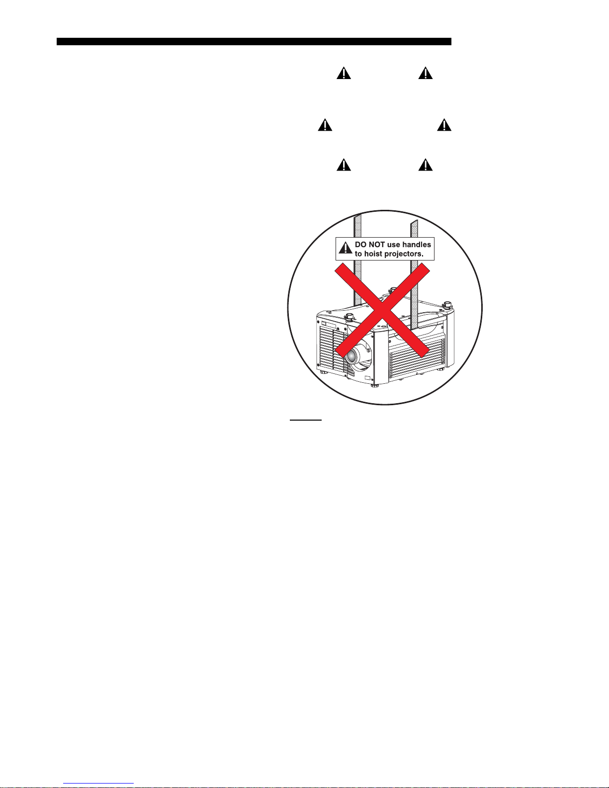
◊ Never hoist a projector by its feet, handles,
or any other component (Figure 2.7).
Figure 2.6. Bottom Rigging
Points
2-4
Roadster/Mirage S+ User’s Manual
INSTALLATION & SETUP
g
WARNING
Use metric hardware only.
Never force incompatible threads.
RECOMMENDED
Remove the lens before hoisting a projector.
WARNING
Never hoist a projector by its feet,
handles, or any other component.
Hoistin
Procedure '
STEP 1 '
STEP 2 '
Figure 2.7. NEVER
Use Handles for Hoisting or as Safety Points
This procedure applies to one or more projectors. To hoist a stack, first stack 2 or 3
projectors according to the stacking procedure included in this manual. Never stack
or hoist more than 3 projectors together.
Remove lens (recommended)
To prevent possible lens damage during hoisting, remove the lens. See 4.4,
Replacing the Lamp and Filter.
Retract feet
Retract the adjustable feet if the projector is inverted to prevent the hoisting hardware
from becoming snagged.
Roadster/Mirage S+ User’s Manual 2-5
INSTALLATION & SETUP
g
STEP 3 '
STEP 4 '
Attach safety cables
Attach a safety cable to each of the (2) eyebolts
mounted on the bottom of the projector (Figure
2.8).
WARNING
Always use at least 2 safety cables for any
hoisting.
WARNING
Attach safety cables
to the 2 eyebolts.
NOTE: When hoisting a non-inverted projector
or stack, add 2 safety eyebolts in the front and
rear threaded holes provided on the top of the
projector. Make sure the eyebolts are rated
adequately for the load. Secure safety cabling
to both eyebolts.
Attach rigging hardware
Secure your rigging components to
the appropriate rigging points—8
sliding points are provided on the
bottom. Tighten the nut at each
required location (Figure 2.9) to
prevent sliding.
Figure 2.8. Attach Safety Cables
NOTE: ADD EYEBOLTS (2)
IF NON-INVERTED
Stackin
2-6
Roadster/Mirage S+ User’s Manual
Procedure '
NOTES: 1) Use at least 4 rigging
points for all hoisting. 2) Use straps,
clamps or cabling with load capacity
adequate for the total projector
weight. See Section 6. 3) Do not join
the rigging straps or cables to a
common point—keep separated as
shown.
WARNINGS
• Maximum stack = 3 projectors.
• Stack first, then hoist.
Figure 2.9. Using the Rigging Hardware
NOTES: 1) Requires stacking hardware provided standard with Roadsters only.
Available separately for Mirage S
Roadster and Mirage S
+
projectors can be stacked in either the upright or inverted
+
. 2) Installation requires at least 2 people.
position. Do not mix orientations—i.e., inverted with upright—in a stack. Secure a
maximum of 3 projectors with the stacking mounts as described below.
INSTALLATION & SETUP
WARNING
Do not stack more than 3 projectors.
STEP 1 '
Christie stacking hardware required. The top
projector could slide off and cause injury or death.
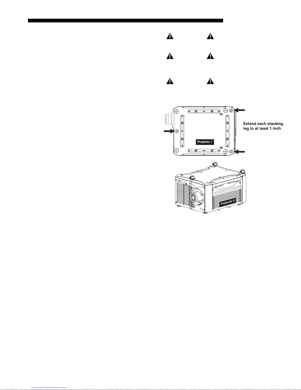
Position the projectors
Place the projectors to be
stacked on a secure table or
cart.
• Place one projector on its
side to access its
adjustable feet and
stacking legs (Figure
2.10).
• Orient the other projector
in either upright or
inverted position as
required (remember,
each projector in a stack
must be in the same
orientation).
WARNING
WARNING
Never carry a stack.
STEP 2 '
Figure 2.10. Adjust the Feet
Fully retract the (4)
adjustable feet
Retract each foot as far as possible by turning it clockwise.
• If upright – retract the feet on top projector.
• If inverted – retract the feet on bottom projector.
Roadster/Mirage S+ User’s Manual 2-7
INSTALLATION & SETUP
STEP 3 '
STEP 4 '
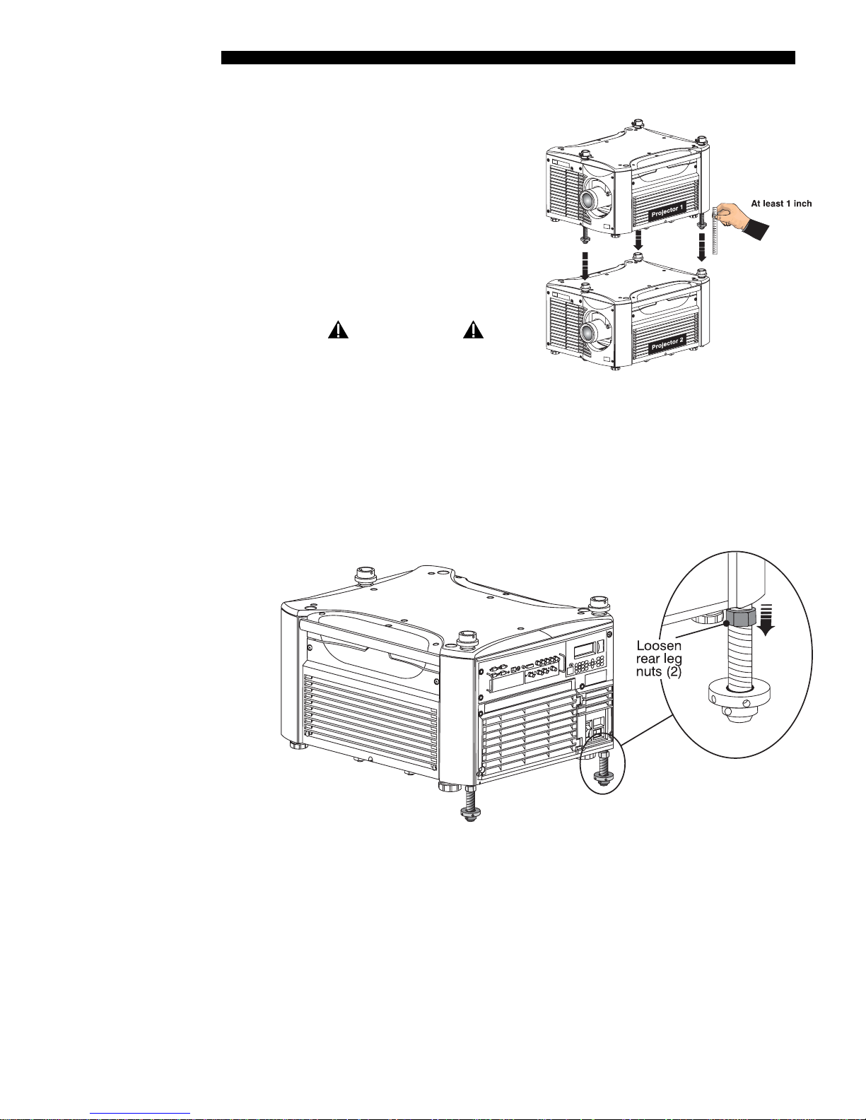
Extend the (3) stacking legs
Extend the stacking legs by turning
them so that at least 1 inch of thread is
visible on each. This clearance
accommodates the up-or-down
movement for aligning the images from
stacked projectors. Extend all 3 legs
equally (Figure 2.11).
• If upright – extend legs on top
projector (shown).
• If inverted – extend legs on bottom
projector.
IMPORTANT
Extend the stacking legs
equally by at least 1 inch.
Figure 2.11. Extend 3 Stacking Legs
(UPRIGHT STACK SHOWN)
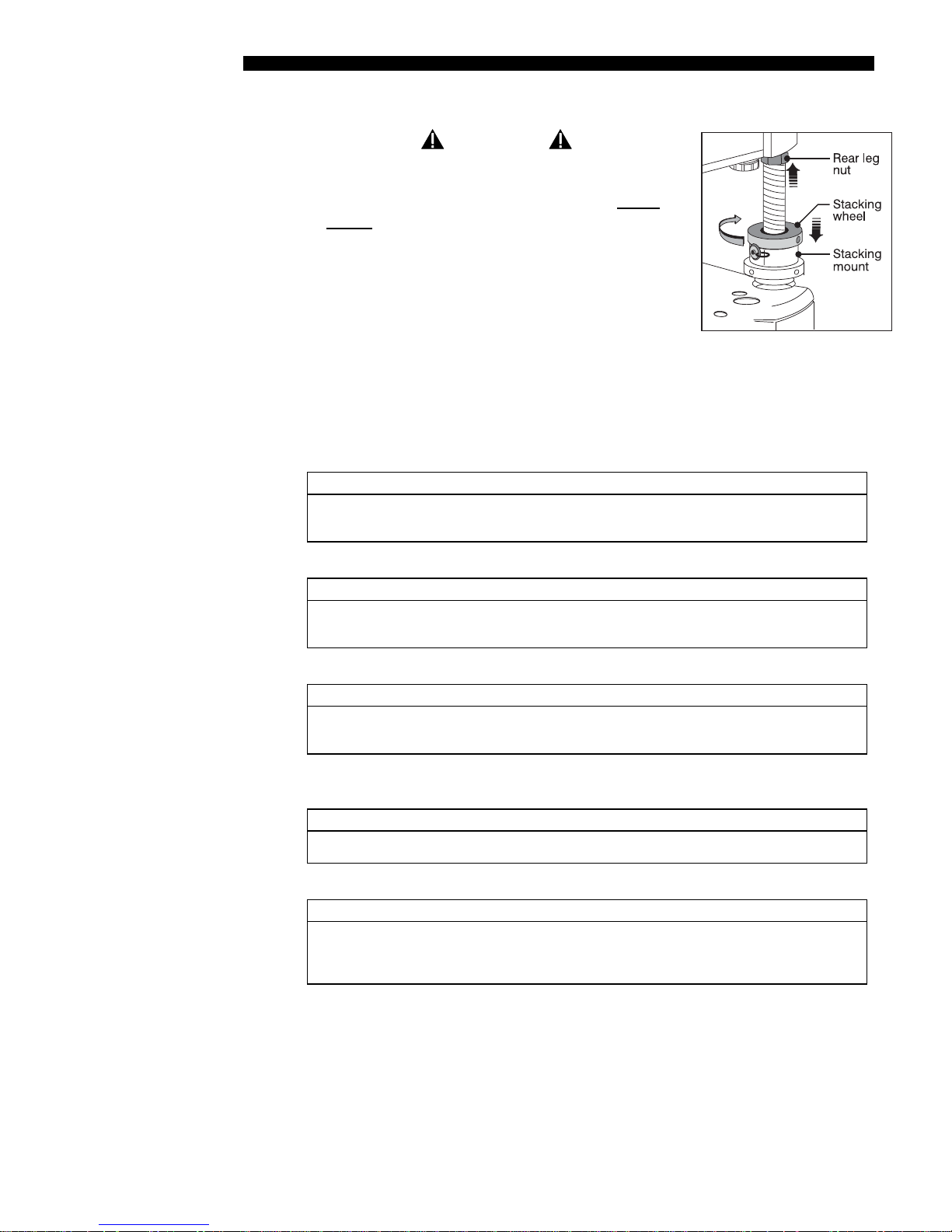
Loosen the rear stacking leg nuts
On the rear stacking legs, loosen the nuts so the legs have some lateral movement for
easier alignment with the stacking mounts on the other projector.
• If upright – release on top projector.
• If inverted – release on bottom projector.
2-8
Roadster/Mirage S+ User’s Manual
Figure 2.12. Loosen 2 Nuts

INSTALLATION & SETUP
STEP 5 '
STEP 6 '
STEP 7 '
Release and remove (3) safety pins
The safety pins must be removed from the
stacking mounts so that the stacking legs can fit
into the mounts (Figure 2.13).
• If upright – remove the pins from the mounts
on the bottom projector.
• If inverted – remove the pins from the
mounts on the top projector.
Figure 2.13. Remove Safety Pins
Place top projector on bottom projector
WARNING
Minimum of 2 people required.
With one person on each side, lift the top projector on to bottom projector, aligning
all three stacking points between projectors. Legs should fit inside stacking mounts.
Align holes in (3) stacking mounts and (3) stacking legs.
On each stacking mount, turn the adjusting wheel slightly until the hole in the top
portion of the mount lines up with the hole in the stacking leg (Figure 2.14).
NOTE: You can increase leverage by using a screwdriver in the holes.
Figure 2.14. Align Holes in Mounts and Legs, and LOCK with Pin
STEP 8
'
Insert (3) safety pins and LOCK all
WARNING
Critical Safety Procedure.
At each of the (3) stacking points, insert the safety pin fully through the holes in the
stacking mounts and stacking legs (Figure 2.14). Ensure that each pin is fully inserted to
engage the safety lock and secure the projectors together. Failure to engage the safety
lock could cause the projectors to separate and result in injury or death.
Roadster/Mirage S+ User’s Manual 2-9

INSTALLATION & SETUP
g
WARNING
Failure to engage the safety lock could cause the
projectors to separate and result in injury or death.
STEP 9
'
Leg Nuts
Before hoisting, firmly tighten the nuts on the (2) rear stacking legs (Figure 2.14). Or,
if you are ready to align the projectors to one another, leave these nuts slightly loose
until after the alignment.
STEP 10 '
Ali
nment Procedure '
Repeat STEPS 1–9 for a third projector.
Stacked projectors must be correctly aligned to one another so that the resulting
display is optimized and as sharp as possible. If you are also hoisting the stack, hoist
the stack into place first, then align. Lock all stacking hardware into place to maintain
your alignment.
Before You Begin
Always align to the fixed projector. In floor-mount or table-mount (i.e., non-
hoisted) stacks, you will align to the bottom projector as shown in drawings
below. In hoisted stacks, align to the top projector.
WARNING
Never stack more than 3 projectors.
IMPORTANT
Make sure the stacking legs have been extended
by at least 1 inch, and are slightly loosened.
Refer back to
Figure 2.11.
STEP 1 '
STEP 2 '
STEP 3 '
STEP 4 '
Leg nuts must be loosened before alignment; otherwise the stacking mounts will
not turn and allow movement of the projector.
Position the first image (fixed projector)
Position the fixed projector’s image as desired and align the other image(s) to it as
described below.
Display the grid test pattern
To distinguish each image, enable “Red” for one display and “Green” for the other.
See 3.3, Using the Keypads if you need help enabling colors.
Adjust zoom and focus
Minimize each projector’s zoom and images are in focus.
Try aligning the two grid patterns
Adjust zoom and offset on the top projector to precisely move its test pattern display
on to the bottom test pattern. When properly aligned, all red/green grid lines in the
combined image will turn yellow.
• If all lines are well aligned, skip to STEP 7 to lock all stacking mounts.
• If alignment needs improvement, proceed with the next step.
2-10
Roadster/Mirage S+ User’s Manual
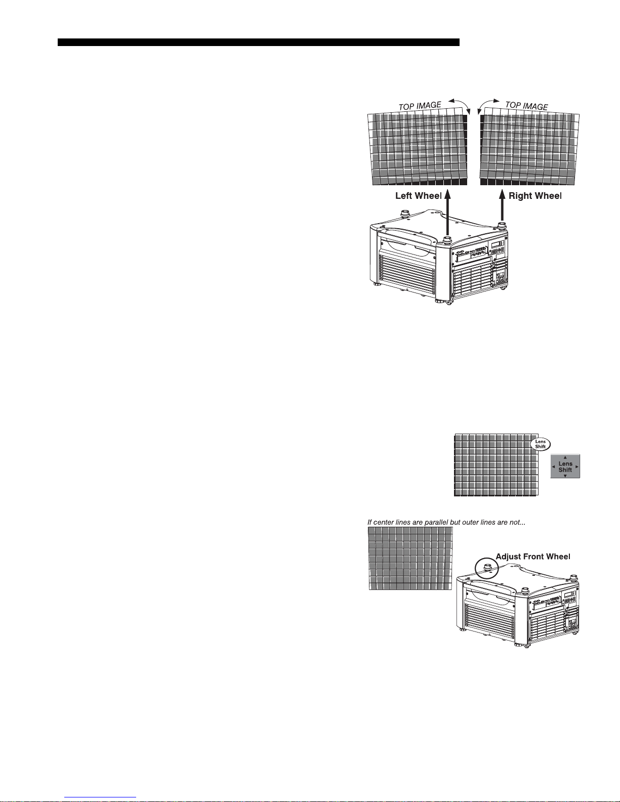
STEP 5 '
Align the centerlines of the grid
Turn the (2) rear stacking mount
wheels to move the top projector
as necessary for well-aligned
centerlines. Use a screwdriver in
the holes around the rim of each
adjusting wheel for better leverage
and control.
HOW TO MOVE THE IMAGE:
Turned independently, each
stacking mount acts as a pivot
point for the opposite edge of the
display (Figure 2.15). For
example, turn the right mount to
tilt the left portion of the image up
or down, and turn the left mount to
tilt the right portion of the image
up or down. Turn together to raise
Figure 2.15. Adjustment Directions (Tilt)
or lower the top image like an
offset adjustment, or turn the front stacker.
INSTALLATION & SETUP
STEP 6 '
IF THE CENTER LINES FORM AN “X”: This indicates that the projectors (and images)
are slightly tilted in relation to one another. Turn one mount to raise one side, and/or
turn the other mount to lower other side. See Figure 2.15.
IF THE CENTER LINES ARE PARALLEL BUT MISALIGNED:
• If centerlines are out by the same amount from top
and bottom – use offsets (on top projector) to bring
the centerlines into alignment.
• If centerlines are parallel but
others are not, turn the front
stacking mount wheel to bring
the centerlines into alignment.
Align the edges of the grid
With centerlines aligned, adjust zoom (top projector) to align the edges of its image
with the other image. Then adjust focus. When aligned, all lines from the combined
red/green grids will be yellow.
Roadster/Mirage S+ User’s Manual 2-11
INSTALLATION & SETUP
n
yp
STEP 7 '
STEP 8 '
I
stallation T
e '
Secure all stacking wheels and leg nuts
WARNING
Critical Safety Procedure.
Turn all (3) stacking wheels until they are firmly
secure against the rest of the stacking mount
(Figure 2.16).
Secure both (2) rear leg nuts against the bottom of
the projector.
Figure 2.16. Secure All
Repeat steps 1 to 7 for a third projector
Hardware
Choose the installation type that suits your needs: front or rear screen, floor mount or
inverted mount.
Front Screen, Floor Mount Installation
ADVANTAGES CONSIDERATIONS
• Easy to set up
• Can be moved or changed quickly
• Easy to access
Front Screen, Inverted Mount (ceiling) Installation
ADVANTAGES CONSIDERATIONS
• Does not take up audience space
• Projector is unobtrusive
• Projector cannot be accidentally moved
Rear Screen, Floor Mount Installation
ADVANTAGES CONSIDERATIONS
• Projector is completely hidden
• Projector is easily accessed
• Usually good ambient light rejection
Rear Screen, Inverted Mount (ceiling) Installation
ADVANTAGES CONSIDERATIONS
• Projector is completely hidden
• Usually good ambient light rejection
Rear Screen, Floor Mount with Mirror
ADVANTAGES CONSIDERATIONS
• Projector is completely hidden
• Usually good ambient light rejection
• Requires less space behind screen than
other rear screen installations
• Shares floor space with audience
• Installation is more permanent
• It is more difficult to access the projector
• Requires separate room
• Requires rear projection screen
• Requires separate room
• Installation cost is usually higher
• Requires separate room
• Installation cost is usually higher
2-12
Roadster/Mirage S+ User’s Manual
INSTALLATION & SETUP
yp
Screen T
e '
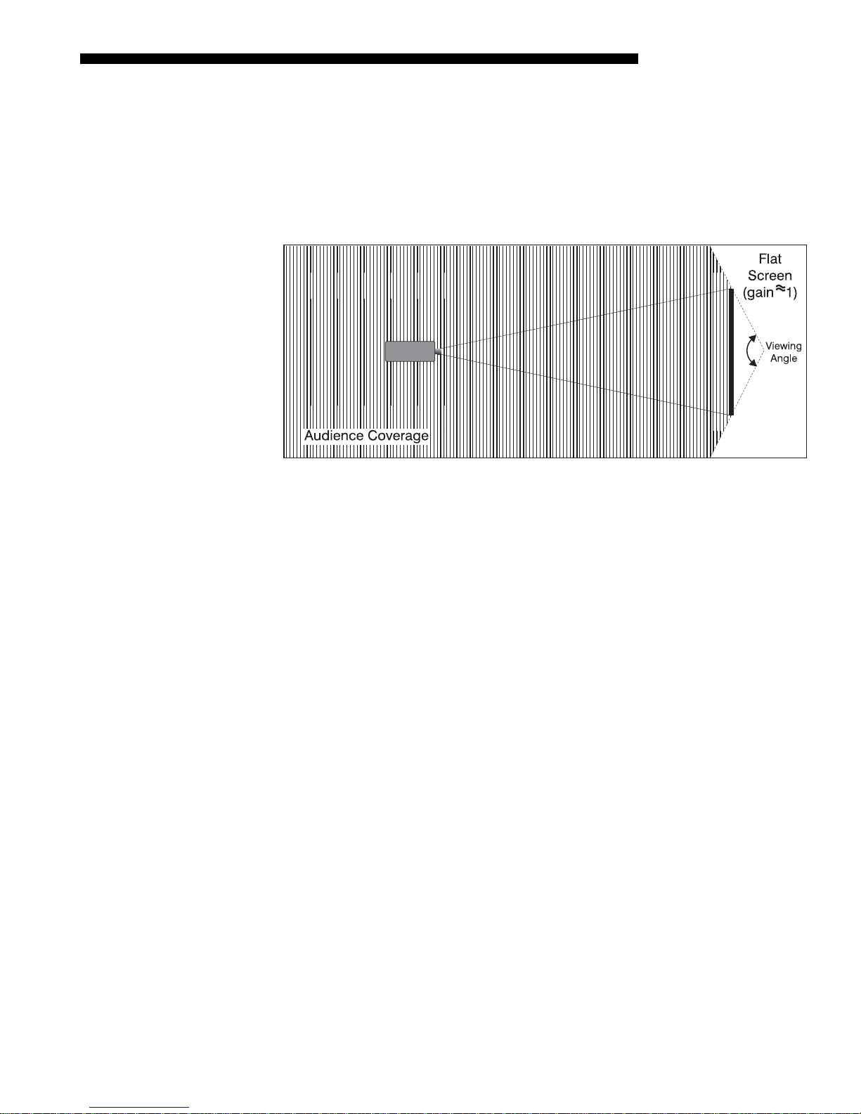
Front Screen Installations
While there are two basic screen types, flat and curved, generally flat screens are
recommended for this projector (Figure 2.17). Flat screens offer a gain of about 1
with a viewing angle just less than 180°. Incident light reflects equally in all
directions so the audience can see the display from various angles. Because of the
low gain, flat screens are most effective when ambient lighting is reduced, although
this difference may be negligible given the high brightness output from this projector.
Figure 2.17. Audience Coverage with Flat Screen
NOTE: Lenses for this projector are designed primarily for use with flat screens, but
the projector depth-of-field range allows the lens to be focused on curved screens as
well. While focus remains sharp in the corners, there may be significant pincushion
distortion, primarily at the top of the screen.
Screen Size '
Rear Screen Installations
There are two basic types of rear screens: diffused and optical . A diffused screen has
a surface that spreads the light striking it. Purely diffused screens have a gain of less
than 1. The main advantage of the diffused screen is its wide viewing angle, similar
to that of a flat screen for front screen projection. Optical screens take light from the
projector and redirect it to increase the light intensity at the front of the screen. This
increase at the front reduces the intensity in other areas. A viewing cone, similar to
that of a curved front screen installation, is created.
To summarize, optical screens are better suited for brightly lit rooms where the
audience is situated within the viewing cone. Diffused screens may be better suited
when a wide viewing angle is required but there is low ambient room lighting.
Screen size may vary from 4 feet (122 cm) to 45 feet (1372cm) diagonal, depending
on the lens you are using. For instance, a 0.73:1 lens can produce a 5 foot (150 cm) to
a 14 foot (548 cm) image size depending on the location of the projector, whereas a
4.5-7.3:1 zoom lens produces an 8 foot (160 cm) to 40 foot (438 cm) image size.
Choose a screen size appropriate for your lens and application. Keep in mind that if
the projector will be used to display text information, the image size must allow the
audience to recognize all text clearly. The eye usually sees a letter clearly if eye-totext distance is less than 150 times the height of the letter. Small text located too far
from the eye may be illegible at a distance no matter how sharply and clearly it is
displayed.
Roadster/Mirage S+ User’s Manual 2-13

INSTALLATION & SETUP
p
g
Ideally, to fill a screen with an image, the aspect ratio of the screen should be equal to
the aspect ratio of the image. The aspect ratio of an image is expressed as the ratio of
its width to its height such as a 4:3 aspect. Standard video from a VCR has a 4:3
aspect ratio. For example, to display a VCR output with a 4:3 aspect ratio onto a 10foot (3m) high screen, the width of the screen must be at least 13.3 feet (4m).
Screen As
ect Ratio '
Ambient Lightin
Aspect ratio describes the proportion of the screen and is expressed as the ratio of
width to height, such as “4:3” or “5:4”. Although image size and image aspect ratio
can both be adjusted quickly through projector software, it is still a good idea to
choose a screen aspect ratio that is most appropriate for your intended applications.
Ideally, to exactly fill a screen with an image, the aspect
ratio of the screen should correspond to the aspect ratio of
the image, which depends on the source in use. For
example, standard video from a VCR has a 4:3 ratio
(approximately), whereas a high-resolution graphics signal
typically has a 5:4 aspect ratio. By default, images from
your projector will be as large as possible and will maintain
their aspect ratio.
Figure 2.18. Aspect
The SXGA+ (1400 x 1050) aspect ratio for the Roadster S
+
and Mirage models is 4:3 (Figure 2.18).
The high brightness of this projector is well suited for locations where ambient
'
lighting might be considered less than ideal for projection. Even a typical room or
large auditorium fully lit with ceiling lights and windows rarely requires special
attention. Contrast ratio in your images will be noticeably reduced only if light
directly strikes the screen, such as when a shaft of light from a window or floodlight
falls on the image. Images may then appear washed out and less vibrant.
Ratio
Other Considerations '
In general, avoid or eliminate light sources directed at the screen.
Other considerations and tips that can help improve your installation:
• Keep the ambient temperature constant and below 35°C (95°F). Keep the
projector away from heating and/or air conditioning vents. Changes in
temperature may cause drifts in the projector circuitry that may affect
performance.
• Keep the projector away from devices that radiate electromagnetic energy such
as motors and transformers. Common sources of these include slide projectors,
speakers, power amplifiers, elevators, etc.
• Choose the best screen size for the application. Since more magnification reduces
brightness, use a screen size appropriate for the venue but not larger than
required. Installing a large screen in a small room is similar to watching
television at a close range; too large a screen can overpower a room and interfere
with the overall effect. A good rule of thumb is to be no closer than 1.5 times the
width of the screen.
2-14
Roadster/Mirage S+ User’s Manual
2.3 Projector
Position and
Mounting
Throw Distance '
INSTALLATION & SETUP
Installation type, screen type, and lighting all affect where the projector is positioned.
In addition, both throw distance (the distance between the projector and screen) and
vertical position (the height of the projector in relation to the screen) must be
determined for every new installation. Both depend on the screen size and lens type
you are using. Make sure that the room can accommodate the required position of the
projector for the chosen screen size.
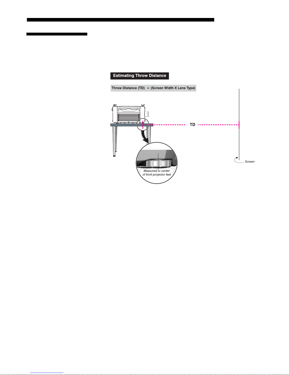
Vertical & Horizontal '
Position
Figure 2.19. Estimating Throw Distance
(SEE APPENDIX D)
For any installation, an accurate throw distance (TD) must be determined in order for
the image to be of the right size for your screen–the farther the projector is from the
screen, the larger the image. Throw distance is the distance between the projector’s
front feet axes and the screen (Figure 2.19), and is roughly equal to the horizontal
width of the screen multiplied by the throw ratio of the installed lens. Once you know
your screen size and lens, you can estimate throw distance needed. For example:
• Screen Width = 10 feet
• Lens Type is 0.7:1
• Throw Distance (TD) = 10 feet x 0.7 = 7 feet
NOTES: 1) If your projector is slightly tilted in relation to the screen, typical for
large venues or flown installations, throw distance still represents the smallest
measurement between the screen and front feet. 2) For proper placement in an
installation, always refer to the throw distance formula and/or chart for your lens as
listed in Appendix D. Keep in mind that due to lens manufacturing tolerances for
lens focal length, actual throw distance can vary ±5% between lenses described as
having the same throw ratio
THE VERTICAL POSITION of the projector in relation to the screen also depends on the
size of the screen and the lens type. Correct vertical position helps ensure that the
image will be rectangular in shape rather than keystoned (having non-parallel sides)
and that image focus and brightness both remain optimized.
Roadster/Mirage S+ User’s Manual 2-15
INSTALLATION & SETUP
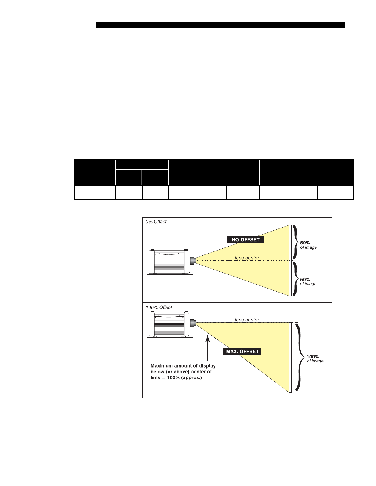
Table 2.1. Maximum Amount of Image Offset from Lens Center
If necessary, vertical position of the image can be offset—that is, moved up or down
in relation to lens center—by using the motorized offset function. Starting with no
offset, the image from this projector can be moved up or down by a maximum
distance of 525 pixels for SXGA+ resolution, resulting in the entire image displayed
above or below lens center. See Table 2.1 and Figure 2.20.
NOTE: Not applicable for the fixed lens.
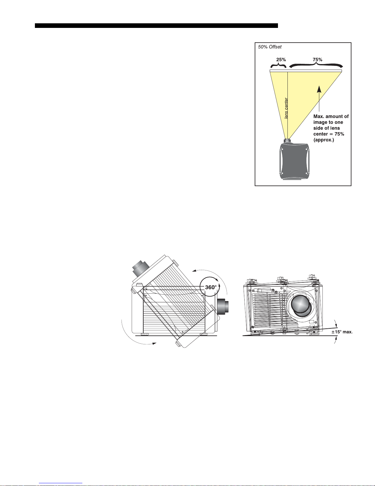
THE HORIZONTAL POSITION of the image can be offset—that is, shifted left or right
of lens center—by using the motorized offset function. Starting with no offset, the
image from this projector can be moved left or right by a maximum distance of 350
pixels for SXGA+ resolution, resulting in 75% of the image displayed to one side of
lens center. See Table 2.1 and Figure 2.21.
Lens Type Offset Movement
(All motorized
lenses)
SXGA+ Lenses 100%
or » or
(525 pix)
NOTES: 1) Offsets are not available with fixed lenses. 2) When offset movement is stated as a percentage (see left
columns), this represents the percentage of ½ image height or½ image width 3) All offset values are ±7%.
(350 pix)
50%
Max. Amount of Display
Above or Below Lens Center
1050 pixels or 100% 1050 pixels » or 75%
Max. Amount of Display
Right or Left of Lens Center
2-16
Roadster/Mirage S+ User’s Manual
Figure 2.20. Maximum Vertical Offset
NOTES: 1) If the image becomes keystoned or
r
exhibits uneven brightness, the projector may
simply be too high or low in relation to the
screen. 2) Recommended offset ranges can be
exceeded, however this may affect image
quality. 3) Simultaneous horizontal and
vertical offset limits the adjustment range of
each. 4) Offset can vary by ±7% and may be
affected by the degree of zoom currently in
use.
INSTALLATION & SETUP
Tilting the Projecto
The projector can be rotated and mounted at any vertical angle—i.e., you can tilt the
'
Figure 2.21. Maximum Horizontal
Offsets
face of the projector up or down as much as desired for your installation. Side-to-side
tilt, however, must not exceed 15° (Figure 2.22). Keeping the projector fairly level in
this manner ensures that the lamp axis is level, and is required for safe and reliable
lamp operation. Always vent exhaust air away from the lens.
Figure 2.22. Vertical and Horizontal Tilt Ranges
CEILING MOUNT: Use only the Christie-approved ceiling mount kit designed for your
projector. Refer to the installation instructions and safety guidelines provided in the
kit. For more information, contact your dealer.
Roadster/Mirage S+ User’s Manual 2-17
INSTALLATION & SETUP
p
g
Folded O
2.4 Source
Connections
tics '
In rear screen applications (Figure 2.23) where space
behind the projector is limited, a mirror may be used
to fold the optical path. The position of the projector
and mirror must be accurately set. Consult your
dealer or Christie for details.
Figure 2.23. Rear Screen
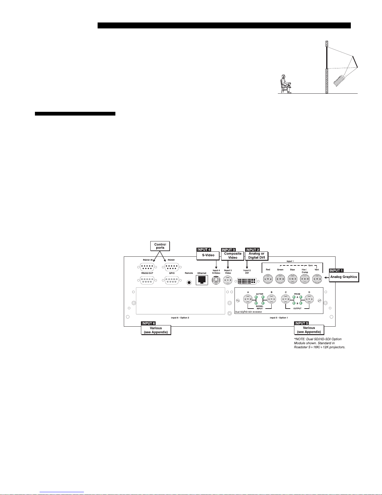
Sources connect to the Input Panel located on the rear of the projector. As shown in
Figure 2.24, the upper right corner (
INPUT 1) typically accepts an RGB signal from
an external analog RGB source, or it can also be used for YPbPr signals or additional
video sources. Just to the left of the BNCs, the DVI-I connector (
INPUT 2) accepts
digital or analog display signals from a computer. Connect analog composite video at
INPUT 3, or S-video at INPUT 4 from devices such as VCRs, laser disk players, or
DVD players. At
compatible SMPTE signals (note this module can be moved to
INPUT 5 (below INPUT 1), connect serial digital YCbCr (4:2:2) or
INPUT 6 if desired).
There are also several optional interfaces available for connecting other sources—
these interfaces slide into the remaining unused option slot, and can be done while
the projector is running.
NOTES: 1) See Section 6, Specifications for details regarding compatible inputs. 2)
Use high quality shielded cables only for all connections. 3) The Dual SD/HD-SDI
module shown is standard on the Roadster models, optional for the Mirage S+ series.
RGB Si
nals '
INPUT 1 consists of 5 BNCs (connectors) for linking to a variety of RGB sources such
as a PC, Mac, DEC, Sun, SGI, and others. This projector supports multiple sync
types with RGB signals: sync-on-green, composite sync, and separate H & V syncs.
NOTE: Depending on your source, you may need a custom adapter cable with BNC
connectors at the projector end and a different type of connector at the other (such as
a 15-pin “D” connector for some computer sources). Contact your dealer for details.
Connect the
outputs to the
sync-on-green, only the red, green, and blue connections are required. If the source
provides a composite sync output, connect it to the
2-18
Roadster/Mirage S+ User’s Manual
Figure 2.24. Input Panel
SYNC BNC input(s) first. Then connect the red, green, and blue source
RED, GREEN, and BLUE BNCs on the INPUT 1 panel. If the source uses
SYNC input labeled HOR/COMP. If
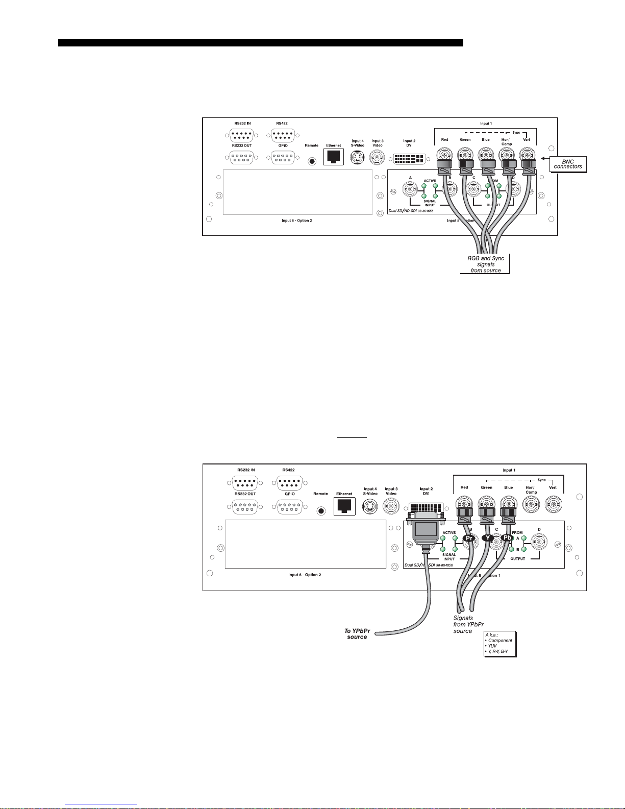
INSTALLATION & SETUP
r
the source provides separate horizontal and vertical sync outputs, connect horizontal
sync to the
labeled
SYNC input labeled HOR/COMP, and connect vertical sync to SYNC input
VERT. See Figure 2.25, below.
YPbP
(COMPONENT VIDEO)
Figure 2.25. Connecting RGB Input
NOTES: 1) If for some reason the projector fails to recognize a signal as an RGB signal,
specify this Color Space option within the Image Settings menu. See 3.6, Adjusting the
Image. 2) To connect YPbPr signals–such as from DVDs or analog HDTV sources–to
INPUT 1, use the red, green and blue BNCs as described in YPbPr Signals (below)
Connect a YPbPr signal (a.k.a. component video) to
'
INPUT 1 or INPUT 2 as shown in.
Figure 2.26.
NOTES: 1) If, for some reason, the projector fails to recognize a YPbPr signal,
specify this Color Space option within the Image Settings menu. See 3.6, Adjusting
the Image. 2) Do not connect digital
. Use the appropriate digital interface option installed at INPUT 5 or 6.
1 or 2
component signals (known as YCbCr) to INPUT
Roadster/Mirage S+ User’s Manual 2-19
Figure 2.26. Connecting YPbPr
INSTALLATION & SETUP
p
p
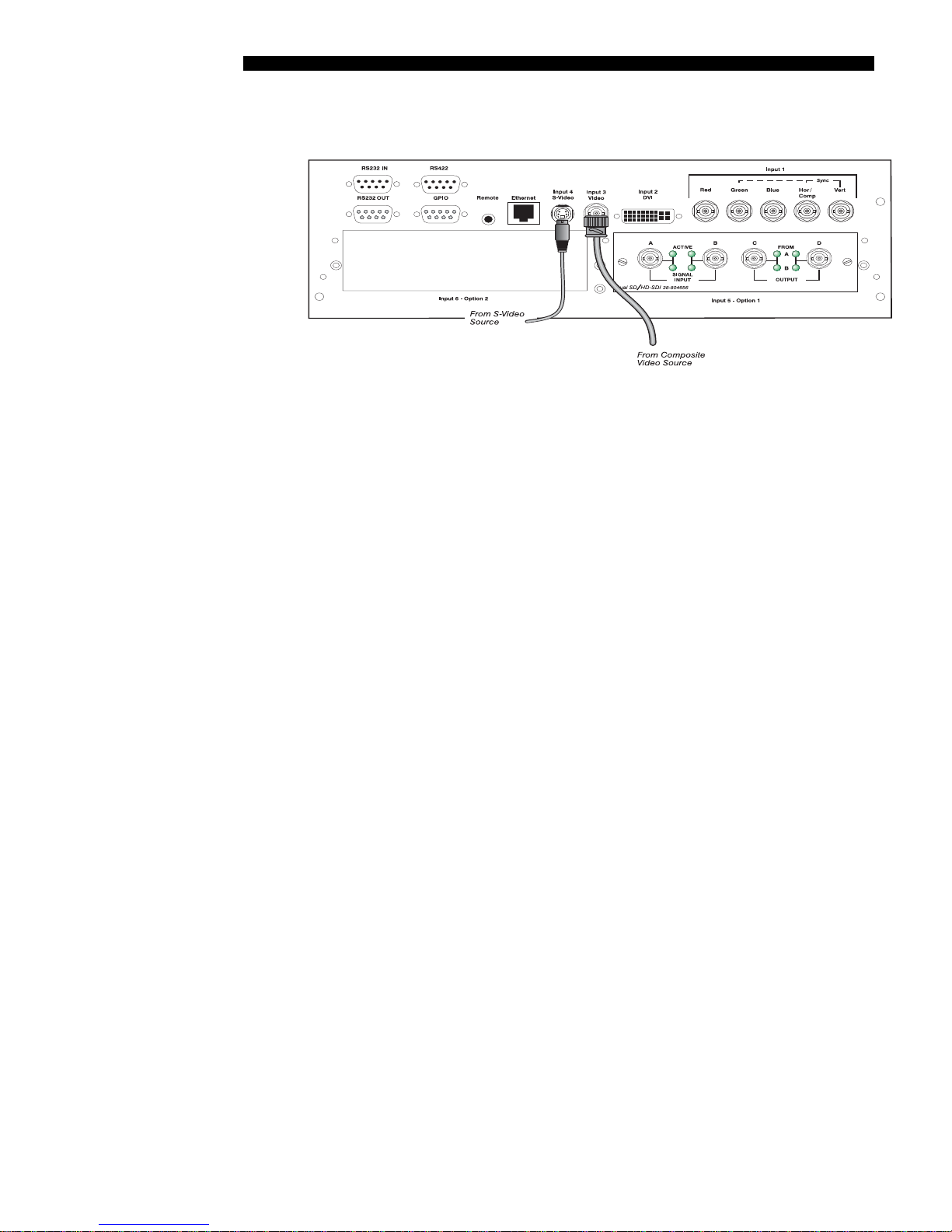
Com
osite Video '
Dual SD/HD-SDI '
INPUT 3 and INPUT 4 provide simultaneous connection of both a composite video
source (
INPUT 3) and an S-Video source (INPUT 4). See Figure 2.27 below.
Figure 2.27. Connecting Composite Video
Christie’s Dual SD/HD-SDI input module is standard with the Roadster S+ and
factory-installed in
INPUT 5 or INPUT 6. The module’s loop-through capability
enables incoming serial digital data to be tiled across multiple screens, creating vast
“mega resolution” displays. Alternatively, the multiple outputs can be overlapped for
extra-bright displays, or simply distributed to additional projectors for multiple
screens of the same image.
The module accepts one or two independent standard- or high-definition serial digital
inputs, decodes them for processing in the main electronics of the projector, and
outputs 10-bit YCbCr 4:2:2 video. Either input can be set as the active primary or
secondary part of a Picture-in-Picture display, and either input can be looped through
to one (or both) of the module’s BNC outputs.
Other Optional In
uts '
NOTE: Selection of these inputs is described in 3.3, Using the Keypads.
Connect a compatible SMPTE 292M or SMPTE 259M-C source(s) to one or both of
the inputs located on the left side of the module. The module will automatically
detect the standard at each input and configure itself accordingly for correct
termination of the signal. The module also detects and supports dual link 292M and
SMPTE 372M video standards. For full details, consult the Dual SD/HD-SDI
manual.
Optional modules allow you to increase your total number of inputs and/or
accommodate different signal types, whether analog or digital. Install in the areas
labeled
INPUT 6 or (if available) INPUT 5. Options include:
• RGB 500 Input Module
• RGB 400BA Input Module
• RGB 400 Active Loop Thru Input Module
• Composite/S-Video Input Module (
software v1.1 or higher)
not currently supported with
• PC250 Analog Input Module
• Serial Digital Input Module
• DVI Input Module
• Dual SD/HD-SDI Module
For even more sources, connect a 3
rd
-party switcher to the RS232 IN port, or, if
(standard on the Roadster series)
RS422-compatible, connect to the RS422 port.
2-20
Roadster/Mirage S+ User’s Manual
INSTALLATION & SETUP
yp
NOTES: 1) Optional digital interfaces cannot be used in a Marquee Case/Power
Supply.2) See Appendix F, Optional Input Modules for a brief description of each
interface.
2.5 Connecting
Communications
Remote Ke
Other Controllers '
ads '
The most common method of controlling the projector is via one of its keypads. As
an alternative, you may wish to communicate using a PC or similar controller. Such a
device sends commands and receives feedback via serial links (2 types), Ethernet or
GPIO communications to the projector, all described below.
As desired, direct the projector’s IR remote keypad towards the display screen or the
projector’s IR sensors. Alternatively, connect the remote keypad by cable to the
remote phono jack (labeled
REMOTE) input at the back of the projector.
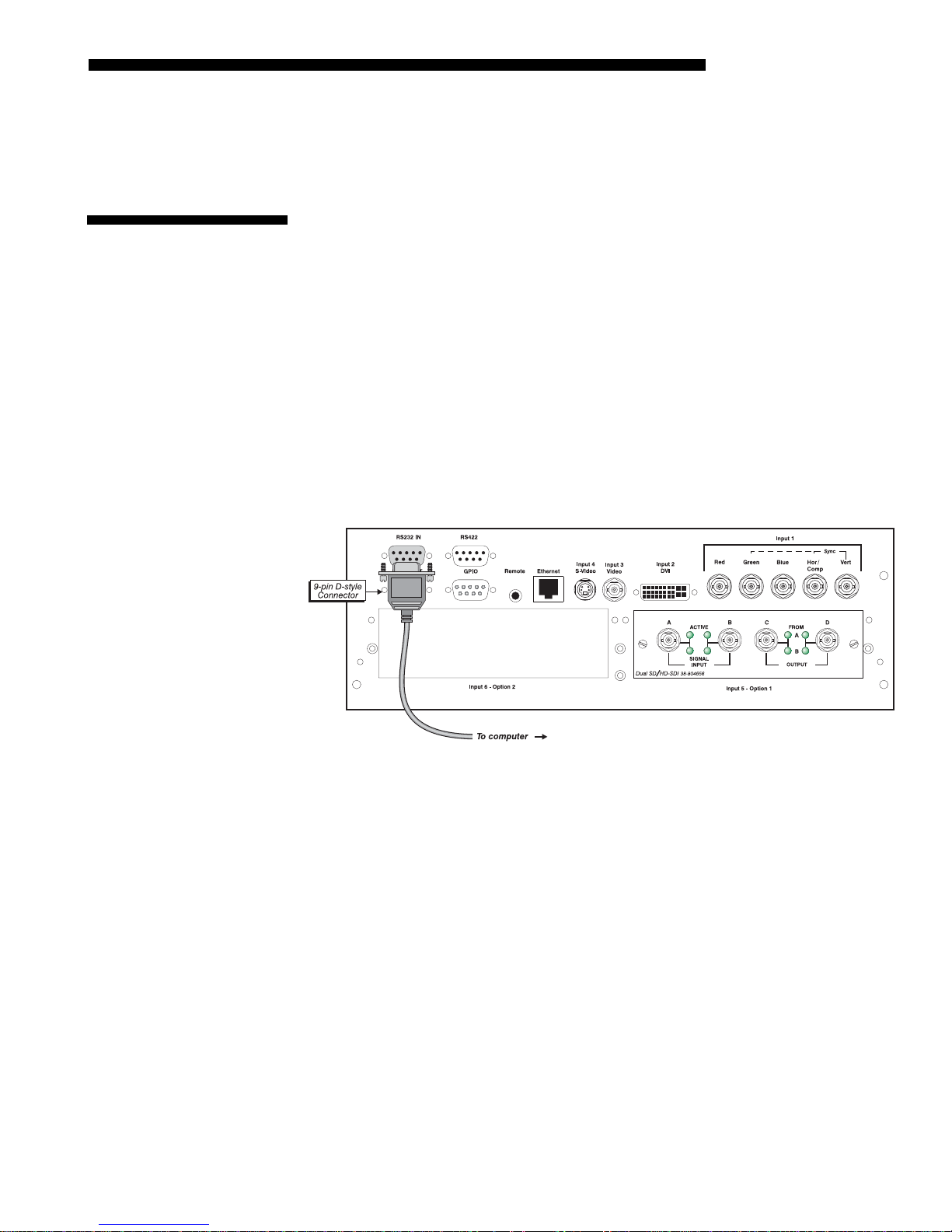
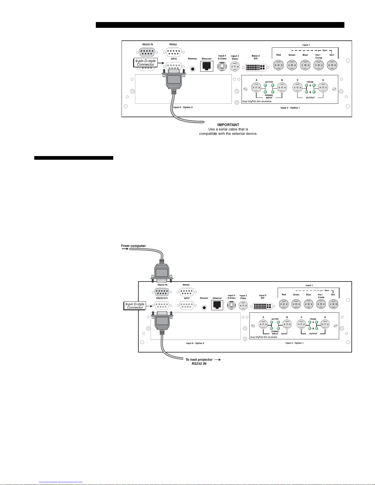
RS232 Serial Communications
From most computers, connect a standard RS232 serial communication cable
between the computer and the projector serial port labeled
RS232 IN—this 9-pin
connector is located on the input panel at the rear of the projector (Figure 2.28). In
the Communications menu, set the projector’s baud rate (default = 115200) to match
that of the computer.
Figure 2.28. RS232 Serial Communications
Changing the baud rate is done in the projector’s Communications submenu. See 3.7,
Adjusting System Parameters and Advanced Controls.
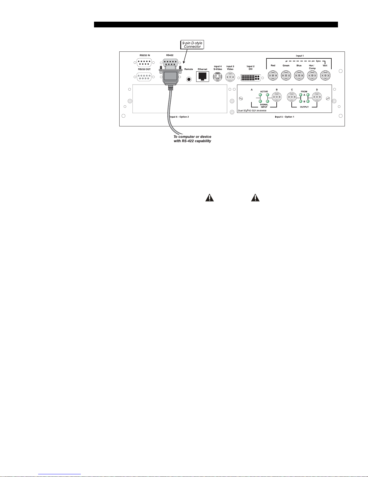
RS422 Serial Communications
Some computers can provide RS422 serial communications (often through a plug-in
adapter or external converter) rather than the more common RS232 standard. RS422
communication has differential “transmits-and-receives” and is generally better
suited for long distances than is RS232 communication. Note that RS422 is not
compatible with RS232—connecting an RS232-compatible PC to RS422 can damage
the equipment at either end. Consult the documentation provided with your PC if you
are unsure.
Roadster/Mirage S+ User’s Manual 2-21
INSTALLATION & SETUP
Figure 2.29. RS422 Connection to a Computer
The nine-pin RS422 connector is located at the rear of the projector (Figure 2.29).
Use this port for communications to and from an RS422-compatible controller. In the
Communications menu, set the baud rate to match that of your RS422 controlling
device.
WARNING
Do not use an RS422 port unless you are using
equipment with RS422 capability. The voltage levels of
this signal can damage incompatible equipment.
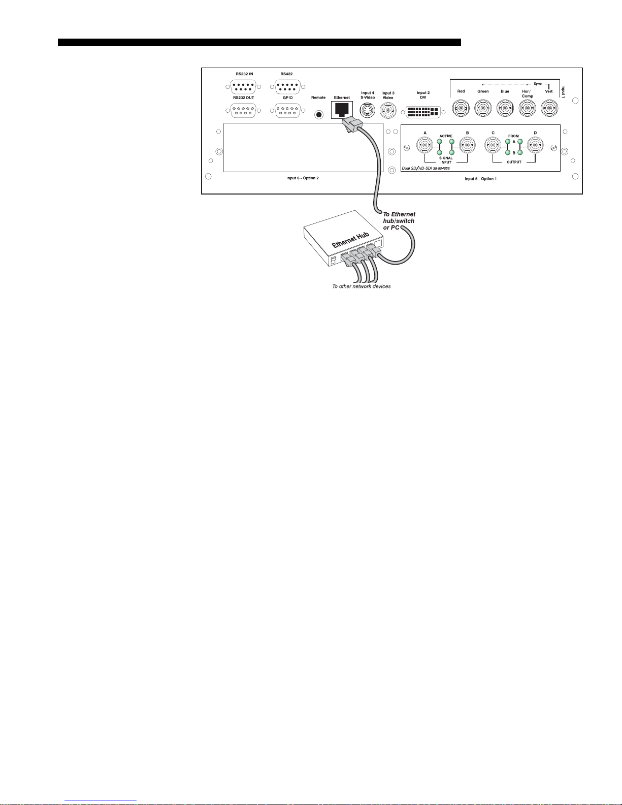
Ethernet Communications
To add the projector to an existing Ethernet network with other equipment such as
controllers and other projectors, connect standard CAT5 Ethernet cable between your
Ethernet controller (or hub) and the Ethernet port at the rear of the projector as shown
in Figure 2.30.
CONNECTING TO A PC: If you are connecting the Ethernet port directly to a PC
(rather than a network or hub), make sure to use a crossover Ethernet cable. Keep in
mind that an Ethernet link cannot be used for downloading a software upgrade to the
projector—use RS232.
2-22
Roadster/Mirage S+ User’s Manual
INSTALLATION & SETUP
Figure 2.30. Connecting Ethernet
Upon connection to an Ethernet network, the projector’s factory default IP address of
0.0.0.0 will automatically enable the DHCP function (if available on the network) to
assign a new IP address that is valid and unique for that network. Or, if there is no
DHCP function available on the network (or if a specific static IP address for the
projector is preferred or required), you can set the address in the Ethernet Settings
submenu or via an ASCII serial command.
NOTE: Make sure the projector is connected to the network before attempting to
change its IP address.
Regardless of how it is assigned, once a projector has a valid and unique address it
will respond to commands sent to this address. To determine the projector’s current
IP address, consult the Status or Communications menus.
Refer to 3.7, Adjusting System Parameters and Advanced Controls for further
information about setting up and using a projector connected via Ethernet.
The GPIO Port
The General Purpose In-Out (GPIO) port enables integration of the projector within
an established control system (Figure 2.31). ASCII commands sent via the GPIO link
are stored in projector memory, where they can be triggered as a sequence of events
in the future. See Appendix E.
Roadster/Mirage S+ User’s Manual 2-23
INSTALLATION & SETUP
Figure 2.31. GPIO Port
2.6 Connecting
Multiple
Projectors
Serial Links '
You may wish to chain two or more projectors together so that commands and
communications to and from a controller are relayed to all projectors. Choose a
hardware configuration that best suits your desired communication method.
RS232 NETWORK: To control multiple projectors with a computer/controller having
an RS232 interface, first set all projectors to the same baud rate as the controller, then
chain the projectors together by connecting the
projector (already connected to the computer/controller) to the
RS232 OUT connector of the first
RS232 IN connector of
the next projector in the chain. Continue connecting projectors in this manner until
you’ve reached the last projector in the chain, so that only the last projector has an
unused
RS232 OUT port. See Figure 2.32.
Figure 2.32. RS232 Serial Link Loop-Through at First Projector
MIXED NETWORK: To control multiple projectors with a computer/controller having
an RS422 interface, first set them all to the same baud rate as your RS422 controller.
NOTE: You must enable this combination of RS422 and RS232 in the
Communications menu. Set the “Network Routing” option to “RS232 and RS422
Joined”. See Section 3 for details.
2-24
Roadster/Mirage S+ User’s Manual
 Loading...