

Page 1

User Guide
020-101948-02
M Series
Page 2

NOTICES
COPYRIGHT AND TRADEMARKS
yright © 2018 Christie Digital Systems USA Inc. All rights reserved.
Cop
All brand names and product names are trademarks, registered trademarks or trade names of their respective holders.
GENERAL
Every effort has been made to ensure accuracy, however in some cases changes in the products or availability could occur which may not be reflected in this
document. Christie reserves the right to make changes to specifications at any time without notice. Performance specifications are typical, but may vary
depending on conditions beyond Christie's control such as maintenance of the product in proper working conditions. Performance specifications are based on
information available at the time of printing. Christie makes no warranty of any kind with regard to this material, including, but not limited to, implied
warranties of fitness for a particular purpose. Christie will not be liable for errors contained herein or for incidental or consequential damages in connection
with the performance or use of this material. Canadian manufacturing facility is ISO 9001 and 14001 certified.
WARRANTY
Products are warranted under Christie’s standard limited warranty, the complete details of which are available by contacting your Christie dealer or Christie. In
addition to the other limitations that may be specified in Christie’s standard limited warranty and, to the extent relevant or applicable to your product, the
warranty does not cover:
Problems or damage occurring during shipment, in either direction.
a.
Projector lamps (See Christie’s separate lamp program policy).
b.
Problems or damage caused by use of a projector lamp beyond the recommended lamp life, or use of a lamp other than a Christie lamp supplied by
c.
Christie or an authorized distributor of Christie lamps.
Problems or damage caused by combination of a product with non-Christie equipment, such as distribution systems, cameras, DVD players, etc., or use
d.
of a product with any non-Christie interface device.
Problems or damage caused by the use of any lamp, replacement part or component purchased or obtained from an unauthorized distributor of Christie
e.
lamps, replacement parts or components including, without limitation, any distributor offering Christie lamps, replacement parts or components through
the internet (confirmation of authorized distributors may be obtained from Christie).
Problems or damage caused by misuse, improper power source, accident, fire, flood, lightening, earthquake or other natural disaster.
f.
Problems or damage caused by improper installation/alignment, or by equipment modification, if by other than Christie service personnel or a Christie
g.
authorized repair service provider.
Problems or damage caused by use of a product on a motion platform or other movable device where such product has not been designed, modified or
h.
approved by Christie for such use.
Problems or damage caused by use of a projector in the presence of an oil-based fog machine or laser-based lighting that is unrelated to the projector.
i.
For LCD projectors, the warranty period specified in the warranty applies only where the LCD projector is in “normal use” which means the LCD projector
j.
is not used more than 8 hours a day, 5 days a week.
Except where the product is designed for outdoor use, problems or damage caused by use of the product outdoors unless such product is protected from
k.
precipitation or other adverse weather or environmental conditions and the ambient temperature is within the recommended ambient temperature set
forth in the specifications for such product.
Defects caused by normal wear and tear or otherwise due to normal aging of a product.
l.
The warranty does not apply to any product where the serial number has been removed or obliterated. The warranty also does not apply to any product sold
by a reseller to an end user outside of the country where the reseller is located unless (i) Christie has an office in the country where the end user is located or
(ii) the required international warranty fee has been paid.
The warranty does not obligate Christie to provide any on site warranty service at the product site location.
PREVENTATIVE MAINTENANCE
Preventative maintenance is an important part of the continued and proper operation of your product. Failure to perform maintenance as required, and in
accordance with the maintenance schedule specified by Christie, will void the warranty.
REGULATORY
The product has been tested and found to comply with the limits for a Class A digital device, pursuant to Part 15 of the FCC Rules. These limits are designed
to provide reasonable protection against harmful interference when the product is operated in a commercial environment. The product generates, uses, and
can radiate radio frequency energy and, if not installed and used in accordance with the instruction manual, may cause harmful interference to radio
communications. Operation of the product in a residential area is likely to cause harmful interference in which case the user will be required to correct the
interference at the user’s own expense.
CAN ICES-3 (A) / NMB-3 (A)
이 기기는 업무용(A급)으로 전자파적합등록을 한 기기이오니 판매자 또는 사용자는 이점을 주의하시기 바라며, 가정 외의 지역에서 사용하는 것을 목적으로 합니다.
ENVIRONMENTAL
The product is designed and manufactured with high-quality materials and components that can be recycled and reused. This symbol
and electronic equipment, at their end-of
to local regulations. In the European Union, there are separate collection systems for used electrical and electronic products. Please help us to conserve the
environment we live in!
-life, should be disposed of separately from regular waste. Please dispose of the product appropriately and according
means that electrical
Page 3

Content
Introduction...................................................... 7
Projector o
Key features...................................................... 7
List of components.................................................. 8
Product documentation................................................8
Related documentation..............................................8
Operating the projector.............................................10
Controlling the projector..............................................10
Using the built-in keypad............................................11
Using the wired remote.............................................11
IR remote keypad................................................11
Logging on to the projector............................................ 13
Managing users....................................................14
Creating a user..................................................14
Changing a password..............................................14
Deleting a user..................................................14
Navigating the web user interface........................................14
Setting the date and time........................................... 16
Changing the language used for menus...................................16
Adjusting the menu appearance....................................... 16
Uploading a logo file.................................................17
Setting the power management parameters..................................18
Configuring the lens.................................................18
Configuring the lamp................................................ 19
Selecting the lamp operation mode..................................... 19
Selecting the lamp mode............................................20
Specifying the amount of power sent to the lamp.............................20
Setting the target brightness......................................... 20
Configuring lamp failover............................................20
Configuring the HDMI output options...................................... 21
Looping video signals................................................21
Performing diagnostics and calibration..................................... 21
verview...................................................7
M Series User Guide 3
020-101948-02 R
Copyright © 2018 Christie Digital Systems USA, Inc. All rights reserved.
ev. 1 (08-2018)
Page 4

Content
Managing channels................................................23
Displaying a list of channels............................................23
Creating a channel..................................................24
Selecting a channel................................................. 25
Selecting an input..................................................25
Copying a channel..................................................26
Editing a channel...................................................26
Deleting a channel..................................................27
Using multiple projectors...........................................28
Tiling an image over multiple screens......................................28
Performing preliminary calibration........................................28
Automatically correcting frame delay issues in tiled images........................ 29
Refining the displayed colors........................................... 29
Matching colors across multiple screens.....................................31
Displaying picture-in-picture.........................................32
Enabling picture-in-picture.............................................32
Selecting the main and picture-in-picture inputs............................... 32
Configuring the picture-in-picture image....................................32
Locking image frames to the input........................................33
Automatically searching for input signals....................................33
Adjusting the image............................................... 34
Automatically optimizing display parameters..................................34
Displaying a test pattern..............................................35
Changing the size and position of the image..................................35
Resizing the image with a preset.......................................35
Resizing and positioning the image......................................36
Cropping an image................................................37
Correcting a keystoned image.........................................38
Adjusting the main image............................................. 40
Configuring the video sources.........................................40
Manually optimizing input levels....................................... 42
Correcting gamma settings.......................................... 44
Adjusting the sharpness of the image....................................45
Selecting the noise reduction filter......................................45
Adjusting the color for the output........................................ 46
Selecting a color space.............................................46
M Series User Guide 4
020-101948-02 R
Copyright © 2018 Christie Digital Systems USA, Inc. All rights reserved.
ev. 1 (08-2018)
Page 5

Content
Applying pre-defined color performance settings.............................47
Defining user color gamuts.......................................... 47
Adjusting the color satur
ation.........................................48
Ensuring brightness uniformity........................................48
Creating a seamless image with edge blending..............................51
Adjusting the intensity of black........................................52
Uploading a gamma file.............................................53
Monitoring and maintaining the projector...............................54
Backing up the configuration and preferences.................................54
Restoring a backup file...............................................54
Performing a diagnositic test using interrogator................................55
Monitoring the projector status..........................................55
Alarm conditions.................................................55
Configuring SNMP................................................56
Adding a scheduled event........................................... 58
Adding a system event.............................................58
Adding a GPIO event.............................................. 59
Adding a function key event..........................................59
LED and key states................................................. 59
Projector status LEDs..............................................60
Maintaining the cooling system..........................................61
Ventilation.....................................................61
Replacing the dust air filter.......................................... 61
Replacing the fog oil filter........................................... 62
Maintaining the optics................................................62
Viewing the lamp history............................................62
Notifying users after a set number of hours of lamp use........................ 62
Replacing the lamps...............................................63
Changing the lamp serial number...................................... 65
Cleaning the projector optics......................................... 65
Cleaning the lens.................................................65
Troubleshooting..................................................67
Projector does not power on............................................67
Lamp does not ignite................................................ 67
Lamp suddenly turns off..............................................68
Flicker, shadows, or dimness........................................... 68
Black LCD screen, no menu displays.......................................68
M Series User Guide 5
020-101948-02 R
Copyright © 2018 Christie Digital Systems USA, Inc. All rights reserved.
ev. 1 (08-2018)
Page 6

Content
Remote keypad does not seem to work.....................................69
The on-screen displa
y menu does not display.................................69
Cannot establish communication with projector................................69
The projector is on, but there is no display...................................70
Severe motion artifacts...............................................70
Image is vertically stretched or squeezed....................................70
Display is jittery or unstable............................................71
Display is faint....................................................71
The upper portion of the display is waving, tearing, or jittering......................71
Portions of the display are cut off or warped to the opposite edge.................... 71
Display appears compressed or vertically stretched............................. 72
Data is cropped from the edges..........................................72
Display quality appears to drift from good to bad, bad to good...................... 72
Display suddenly freezes..............................................72
Inaccurate display colors..............................................73
Display is not rectangular............................................. 73
Display is noisy....................................................73
After a projector software upgrade, the Web UI does not display correctly...............74
A backup or interrogator file cannot be saved.................................74
DMX/ArtNET..................................................... 75
Lens control limitations...............................................75
DMX channel setup................................................. 75
M Series setup personality...........................................76
M Series show personality...........................................80
M Series Nitro VIP projector yoke personality...............................82
M Series User Guide 6
020-101948-02 R
Copyright © 2018 Christie Digital Systems USA, Inc. All rights reserved.
ev. 1 (08-2018)
Page 7

Introduction
This manual is intended for professionally tr
systems.
Only Christie qualified technicians who are knowledgeable about the hazards associated with
highvoltage, ultraviolet exposure, and the high temperatures generated by the projector lamps are
authorized to assemble, install, and service the projector.
For complete M Series product documentation and technical support, go to www.christiedigital.com.
ained operators of Christie high-brightness projection
Projector overview
The M Series is a family of high resolution video/graphics three chip 1080p HD, SXGA+, and WUXGA
projectors. These projectors are based on next generation DLP™ technology provided by Texas
Instruments.
The projector accepts data/graphics and video input signals for projection onto front or rear screens.
Light is generated by dual mercury lamps, then modulated by three Digital Micro-mirror Device (DMD)
panels that provide digitized red, green or blue color information. Light from the ON pixels of each
panel is reflected, converged, and then projected to the screen through a single front lens, where all
pixels are perfectly superimposed as a sharp full-color image.
The projector is configured through a on-screen display (OSD) menu system displayed on the image,
controlled by an IR remote, wired remote, or through the built-in keypad. The LCD screen and built-in
keypad allow some functions to be controlled without the need of the OSD, and provide an accessible
interface to view error reporting. The functions on the OSD can also be controlled using the Christie
serial protocol, through a serial or Ethernet connection to the projector. The web interface provides
access to the menu system as a virtual OSD and to features that maintain the software and settings.
Key features
Understand the important features of the projector.
• Up to 14,000 lumens
• HD (1080p), SXGA+, or WUXGA resolution
• Dual Mercury lamp illumination with 350W and 450W options
• Contrast aperture providing up to 10,000:1 contrast ratio (available on 350W models)
• Ultra-compact design and weighs less than 55lbs
• 10-bit image processor electronics with modular design
• Fully sealed optical system
• Active fan control for minimum noise level
• Selectable, motorized Yellow Notch Filter for expanded color gamut
• User interchangeable projection lenses with no-tool mounting
• Picture-in-picture (PIP)
M Series User Guide 7
020-101948-02 R
Copyright © 2018 Christie Digital Systems USA, Inc. All rights reserved.
ev. 1 (08-2018)
Page 8

Introduction
• LiteLOC for constant brightness maintenance
•
Intelligent Lens System (ILS)
• Motorized lens mount for all models
• Auto-setup feature
• Integrated ChristieNET
• Networking ability through RS232 and RS422 connectors
• Status LED display on built-in keypad for easy projector status monitoring
• Control with remote keypad, wired remote, or built-in keypad
• Four input slots for Optional Input Modules
List of components
Ensure the following components were received with the projector.
• IR remote keypad (includes two, 1.5V AA batteries and an XLR to mini-stereo cable conversion
to wired)
• Line cord
• Lens mount security screw (M6 x 10 mm long, Qty. 2)
• Lens mount security screw (5 mm Hex, Qty. 1)
• Warranty card
• Web registration form
Product documentation
For installation, setup, and user information, see the product documentation available on the Christie
Digital Systems USA Inc. website. Read all instructions before using or servicing this product.
1. Access the documentation from the Christie website:
• Go to this URL:http://bit.ly/2OsZQ2I or https://www.christiedigital.com/en-us/business/
products/projectors/3-chip-dlp/m-series.
• Scan the QR code using a QR code reader app on a smartphone or tablet.
2. On the product page, select the model and switch to the Downloads tab
Related documentation
Additional information on the projector is available in the following documents.
• M Series Installation and Setup Guide (P/N: 020-101941-XX)
.
M Series User Guide 8
020-101948-02 R
Copyright © 2018 Christie Digital Systems USA, Inc. All rights reserved.
ev. 1 (08-2018)
Page 9

• M Series Product Safety Guide (P/N: 020-102690-XX)
• M Series Service Guide (P/N: 020-100551-XX)
• M Series Serial API Commands Technical Reference (P/N: 020-100224-XX)
Introduction
M Series User Guide 9
020-101948-02 R
Copyright © 2018 Christie Digital Systems USA, Inc. All rights reserved.
ev. 1 (08-2018)
Page 10

Operating the projector
Learn how to oper
ate the projector.
Controlling the projector
Understand the controls and switches used for basic projector operation once it is properly installed,
aligned and configured by a Christie accredited service technician.
Warning! If not a
• LASER RADIATION! Do not look directly into the laser beam of the remote.
The projector is typically controlled using either the remote or built-in keypad. While each of the
eypads provides complete control of the projector, they differ slightly in their arrangement of keys
k
and in what functions can be accessed directly with a key press rather than requiring use of the menu
system. You may find one keypad more convenient than another for your specific installation and
application.
• Remote keypad—For wired or wireless control up to 25 feet (8 m) away. The remote keypad
controls the projector by way of wireless communications from a battery-powered infrared (IR)
transmitter. Use the remote keypad the same way you would use a remote keypad supplied
with a TV or VCR. When pressing a function key, direct the keypad toward the projector’s front
or rear IR sensor. One of the two IR sensors on the projector detects the signal and relay the
commands for internal processing. A laser pointer is built into the remote keypad.
• Built-in keypad—Located at the side of the projector.
Keep these guidelines (common to both keypads) in mind:
• Press keys one at a time; there are no simultaneous key combinations required. Use Power,
Shutter, and OSD functions by doing one of the following:
• Press and hold the button for two seconds.
• Press the button twice quickly, followed by pressing either the Up key to switch on or the
Down key to switch off once.
• In serial networks, pause briefly between adjustments to make sure that more distant
projectors can keep up with the commands. If you press a key while the projector is still
responding to the previous action, such as during power-up, the second key press may not
take effect.
As an alternative to using a keypad, most projector functions can be controlled remotely, typically at a
controller such as a PC, through a web interface.
• ASCII Messaging—Connect a serial link between your controller and the RS232 or RS422
port (recommended), or open an Ethernet socket, for example Telnet, between your controller
and the valid projector address. Valid ASCII codes and messages are documented in M Series
Serial API Commands Technical Reference (P/N: 020-100224-XX).
• Web Interface—Connect the PC to the projector’s Ethernet port. In the web browser, enter
the IP address of the projector you wish to control. The default login ids are: admin, service,
and guest.
voided, the following could result in death or serious injury.
M Series User Guide 10
020-101948-02 R
Copyright © 2018 Christie Digital Systems USA, Inc. All rights reserved.
ev. 1 (08-2018)
Page 11
Operating the projector
Up to a maximum of three users can connect at any given time. Two users can use the same
account to log in. Each user sees a different set of tabs. The default passwords can be edited
b
y an administrator or a service user in the Admin tab. Guest users do not see this tab. Basic
operations of the projector can be controlled from this interface and the Virtual OSD can be
accessed from here.
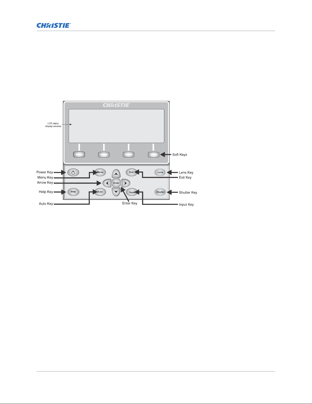
Using the built-in keypad
The built-in keypad has a LCD status display window which displays all states of the keypad controls.
The LCD displays status information when the projector is powering up and when the projector is
cooling down. The displa
y shows the state of the keys, menu structure, and menu items.
Using the wired remote
Convert the remote keypad into a wired remote keypad using any standard 3-pin XLR cable (male to
female).
Connect one end into the remote and the other to the XLR connector on the Wired Keypad input panel.
The wired remote is recommended when:
• The built-in keypad is inaccessible.
• The lighting conditions are unsuitable for proper IR transmission
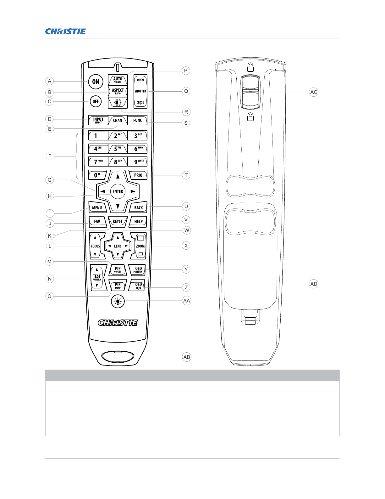
IR remote keypad
The IR remote keypad controls the projector by way of wireless communications from a batterypowered infrared (IR) transmitter.
To use the IR remote, direct the keypad toward the projector’s front or rear IR sensor and press a
function key. One of the two IR sensors on the projector detect the signal and relay the commands for
internal processing. The remote also offers a connector for wired connections to the projector.
M Series User Guide 11
020-101948-02 R
Copyright © 2018 Christie Digital Systems USA, Inc. All rights reserved.
ev. 1 (08-2018)
Page 12
Operating the projector
Button Description
A Powers on the projector light source.
B Opens the aspect ratio dialog.
C Turns off the light source and puts the projector in standby.
D Selects an active or inactive input on any slot.
E Not supported.
M Series User Guide 12
020-101948-02 R
Copyright © 2018 Christie Digital Systems USA, Inc. All rights reserved.
ev. 1 (08-2018)
Page 13

Button Description
F Enter a number, such as menu, item index or value.
G Use the arrows to navigate within a menu or to adjust settings.
H Selects a highlighted menu item and changes or accepts a value.
I Toggles the menus on/off.
J Not supported.
K Opens the keystone dialog.
L Adjusts the lens focus.
M Not supported.
N Displays a test pattern.
O Not supported.
P Optimizes the image automatically.
Q Opens or closes the shutter.
R Not supported.
S Initiates a custom action when a number is selected.
Operating the projector
T Selects a projector in multi-projector installations.
U Returns to the previous menu level or exits menus if at the top level.
V Displays context-sensitive help.
W Arrows adjust the lens offset.
X Adjust the lens zoom.
Y Opens the on-screen display position menu.
Z Shows or hides the on-screen display menus.
AA Turns the remote backlight on.
AB Male 3-pin XLR connector for wired option.
AC Lock/unlock the keypad.
AD Battery door.
Logging on to the projector
Before logging on to the system, ensure that the appropriate language is selected.
The language selection only affects the web user interface. The language used b
display (OSD) is not affected.
1. Open your web browser and type the IP address (in the address bar) assigned to your
projector.
2. In the upper left- hand corner, select the appropriate language.
3. Type your username and password. Both entries are case-sensitive.
y the on-screen
M Series User Guide 13
020-101948-02 R
Copyright © 2018 Christie Digital Systems USA, Inc. All rights reserved.
ev. 1 (08-2018)
Page 14

4. Click Login.
Managing users
Operating the projector
Learn how to create new user accounts, and how to remo
credentials consisting of both a user name and password that allows access to projector settings.
ve the accounts. A user account is a set of
Creating a user
Adding a user account allows users to access projector menus.
1. Click Admin > Users.
2. Click Add User.
3. Type the username and password.
Do not use capitalization for usernames or passwords. If capitalization is used for the
username or password, it is automatically converted to lower case. Usernames can be a
minimum of four and maximum of 32 characters. Passwords can be a minimum of four and
maximum of 128 characters.
4. Re-type the password.
5. Click OK.
Changing a password
Periodically change a user account password to limit access to projector menus and functionality to
authorized users.
1. Click Admin > Users.
2. Select the user.
3. Click Change Password.
4. Complete the Password and Re-type Password fields.
5. Click OK.
Deleting a user
To prevent access to projector menus and functionality, delete a user.
1. Click Admin > Users.
2. Select the user that you wish to remove.
3. Click Delete User.
4. In the confirmation dialog click Yes.
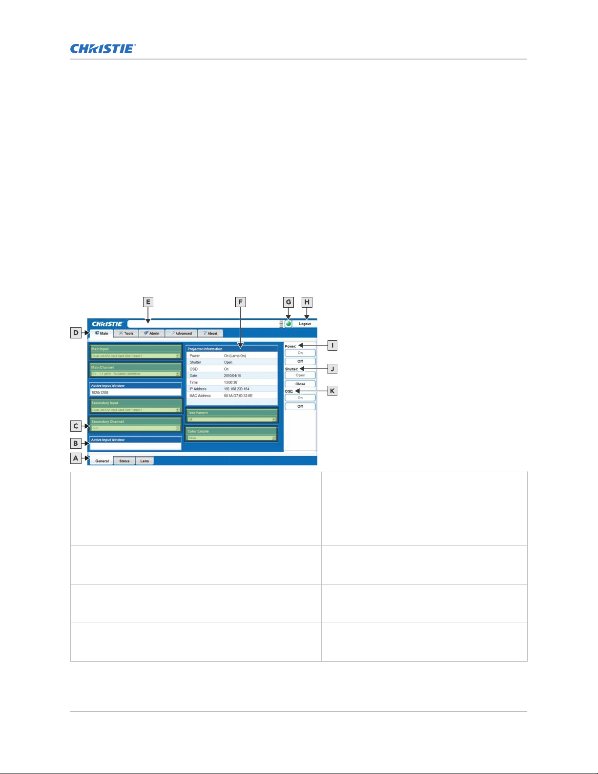
Navigating the web user interface
Understand the areas of the web interface.
Most of the projector controls are accessed from within the menu system. Several groups of related
functions are selectable from the Main menu.
M Series User Guide 14
020-101948-02 R
Copyright © 2018 Christie Digital Systems USA, Inc. All rights reserved.
ev. 1 (08-2018)
Page 15
Operating the projector
On the remote keypad, enter the number that corresponds to the function menu you want to access,
such as 2 for the Image Settings menu. Or use the Up/Down Arrow K
ey on any keypad to highlight the
required option, then press Enter. The corresponding function menu or pull-down list of further
options appear.
With a function menu displayed, enter a menu option number for any numbered option, or use the Up/
Down Arrow Key to highlight the required option and then press Enter. Long menus have a scroll bar
on the right; use the arrow keys to access the remainder of the menu. Locked items or items that do
not pertain to the current action or condition appear dimmed and cannot be selected.
If no signal is present, all source-dependent adjustments are disabled. After 15 minutes of inactivity,
the projector leaves the menu system and returns to the presentation. When finished with a function
menu:
• To return to the previous screen press Exit.
• To leave the menu system and return to the presentation, press Menu.
When navigating the web interface, it is not recommended that you use the web browser navigation
functionality (such as, the Back and Forward functions) as this causes you to lose your web
connection. Christie recommends you navigate using the application interface and related functionality
detailed in this section.
A Secondary Tabs (specific to a primary tab) located
along the bottom of the Main window
B Active Input Window section is read-only. H Logout button (located at the top right corner of
C These sections provide list selections. I Power section contains an On and Off button. Only
D Primary Tabs located along the top of the Main
window.
M Series User Guide 15
020-101948-02 R
Copyright © 2018 Christie Digital Systems USA, Inc. All rights reserved.
ev. 1 (08-2018)
.
G Status Indicator displays the overall status of the
projector, based on the 12 categories of
information available.
Click the Status Indicator LED to display the
Status window and obtain more information about
any current errors and warnings.
the web browser) is used to log you off of the web
user interface and the projector.
one is enabled depending on the current powered
state of the projector.
J Shutter section contains an Open and Close
button. Only one is enabled depending on the
current state of the projector’s shutter.
Page 16

Operating the projector
E Current Status Bar provides information messages
according to the current status of the projector
F Projector Information section is read-only.
K OSD (on-screen display) section contains an On
.
and Off button. Only one is enabled depending on
the current state of the projector’s on-screen
display.
Setting the date and time
Configure the date and time of the projector
Any change to the date and time resets the projector real-time clock.
1. Click Configuration > Date & Time.
2. Change the date and time.
3. Click OK.
.
Changing the language used for menus
Choose the available language to use in the projector menus.
In the Configuration menu, select the language from the list.
The change takes effect immediately.
Adjusting the menu appearance
Change the appearance, content and/or location of on-screen menus and messages.
1. Select Configuration > Menu Preferences.
2. Configure the following:
• Large Menu Font—Enter a check mark to enlarge menus and their text.
• Menu Location—Use the pull-down list to choose a pre-defined default or customized
location for the display of all on-screen menus.
To create a custom menu location:
a. Choose a preset that is closest to the desired location.
b. Adjust Horizontal Shift and Vertical Shift slide bars to move the menu to the
desired location. Avoid locations too close to a corner or edge to prevent cropping of
larger menus.
• Display Automatic Message Boxes—Enable or disable the pop-up of automatic
message boxes. These are messages to the user that are not directly triggered by user
actions. Examples are signal information, function limitation, or auto calibration message
boxes.
• Display User Message Boxes—Enable or disable the pop-up of message boxes that are
directly triggered by user actions, for example gamma or lens control message boxes.
• Display 3D Message Boxes—Enable or disable message boxes that are triggered by 3D
setup errors.
• Display Error Messages—Choose how to be notified of errors detected in either the
incoming signal or projector.
M Series User Guide 16
020-101948-02 R
Copyright © 2018 Christie Digital Systems USA, Inc. All rights reserved.
ev. 1 (08-2018)
Page 17

Operating the projector
• Screen or All (default) to see brief on-screen messages. This is recommended during
setup or testing of the projector
.
• Serial Ports to receive messages through RS232 or RS422 serial communication only.
To hide error message displays, such as during shows and presentations, select Off or
Serial Ports.
• Splash Screen Setup—Choose when to display a special introductory splash screen
image, such as your company logo, graphic or message.
• Always Off—A splash screen never appears
• Start-up Only—The splash screen logo appears at projector start-up only.
• Start-up And No Signal—A splash screen appears at start-up and at any time when
there is no signal.
To add your own splash screen in addition to the default Christie logo splash screen, use
the Web UI to download the desired bitmap (.bmp) file to the projector. This overwrites
any other user splash screen that has been downloaded. Only one user splash screen can
be saved in the projector.
• OSD Transparency—Check this box if you want the OSD menu backgrounds to be
transparent.
• Menu Type—Select the Basic or Advanced menu type from this list box.
• The Basic menu setting gives a small number of the most frequently used menu
items.
• The Advanced menu setting gives the menu options.
• Splash Screen—Choose which splash screen is to be used; the default or user
downloaded splash screen.
• Cascading Menus—Enable or disable cascading menus. When disabled, a single menu
level is displayed on the OSD at a time.
Uploading a logo file
The projector must be powered on to enable the Upload drop-down list.
1. Click Admin > System.
2. To open the Choose file window, click Upload Browse.
3. Locate and select the file to upload from a network drive location or from a hard drive.
4. Select Logo as the file type.
The file must be a 24-bit bitmap file to enable the Logo Position and Background Color section.
5. Enter the position in the X and Y fields.
6. Click the color square and choose the background color from the color palette.
7. Click OK.
The color square changes to the selected color.
8. Click Upload.
9. In the Display Name field enter a descriptive name.
10. To confirm the upload click Yes.
M Series User Guide 17
020-101948-02 R
Copyright © 2018 Christie Digital Systems USA, Inc. All rights reserved.
ev. 1 (08-2018)
Page 18

Operating the projector
Setting the power management parameters
Configure the projector to reduce the amount of power used.
Select Configuration > Power Management.
1.
2. Configure the following:
• LCD Backlight—The backlight for the LCD has three states. Always On, Always Off, or
Timer. The backlight turns on again when any key on the LCD is pressed or if an alarm is
raised.
• LCD Backlight Timer—Sets how long the LCD backlight stays on (in seconds) when in
timer mode.
• LCD Backlight Level—Sets the LCD backlight brightness level. Maximum 25/Minimum 0.
• Auto Power Up—If there is an AC power interruption, while Auto Power Up is enabled,
the projector resumes operation in the same state as it left off. If the lamps are on and an
image showing when AC power is lost, the projector automatically powers back up with
the lamps on and an image shows when AC is restored.
• Auto Shutdown Enable—When Auto Shutdown Mode has been selected, and no
projector activity has been seen for the activation time-out period, the projector enters a
power saving mode in which the lamps dim and the shutter closes.
If this condition persists for an additional time-out period, the projector automatically goes
to Standby mode. The presence of any activity within this combined interval cancels Auto
Shutdown and returns the projector to normal operation.
• Turn Off Image After (Min)—Sets the activation interval (in minutes) for Auto
Shutdown. If all activity (input signals, web or serial port activity, key presses) is lost for
this length of time, and Auto Shutdown is enabled, an Auto Shutdown cycle begins.
• Enter Standby After (Min)—Sets the interval (in minutes) between starting Auto
Shutdown and entering Standby mode. Once Auto Shutdown has been entered, and all
activity continues to be absent for this interval, the projector automatically enters power
Standby mode.
• Lamp Regeneration Start Time—Sets the time of day (in 24 hour format) when the
regeneration cycle starts. For 24/7 operation, the lamp regeneration cycle is required or
lamp life is reduced.
In Dual Lamp mode, the cycle is performed on each lamp separately. The second lamp
waits for the first lamp to come back on before it begins the cycle. In single lamp mode,
the projector goes into Standby mode for the regeneration cycle. The regeneration cycle
runs for 15 minutes for each lamp. The lamp(s) must run for a minimum of 24 hours or
the regeneration cycle is skipped.
• Over-temp Fan Assist—Causes all fans to come on at full speed if any enabled thermal
sensor has an over-temperature fault. This may help to prevent an emergency shutdown if
the extra cooling can bring the temperature within limits before the shutdown occurs. The
fan assist causes increased noise levels due to the simultaneous full speed operation of all
the fans. Normal operation resumes when all over-temperature conditions are removed or
fan assist is turned off.
Configuring the lens
Identify the settings for the lens.
1. Select Configuration > Lens Settings.
M Series User Guide 18
020-101948-02 R
Copyright © 2018 Christie Digital Systems USA, Inc. All rights reserved.
ev. 1 (08-2018)
Page 19

Operating the projector
2. Configure the following:
• Intelligent Lens System—Enables the Intelligent Lens S
lens position (horizontal, vertical, focus, and zoom offsets) are stored per channel. If you
change channels, the lens position changes as the new signal is being displayed. When ILS
is not enabled, the lens is controlled independently of channels or input signals.
• Manual Zoom/focus—When this control is selected, the holding current is removed from
the zoom and focus motors so that they can be changed manually. Zoom and Focus should
not be adjusted manually when this control is not selected, as this results in damage to
the motors.
• Calibrate—The lens calibration procedure is needed each time a new lens is installed in
order for the ILS feature to perform reliably. This procedure calibrates; horizontal, vertical,
focus, and zoom offset movements.
• Lock All Lens Motors—Prevents all lens motors from moving. It disables the Zoom,
Focus, Horizontal and Vertical Position settings, effectively locking out any changes and
overriding all other lens features. This prevents accidental lens position changes in multiprojector installations.
• Calibrate On New Lens—Prompts for a lens calibration each time a lens is inserted. The
user is always prompted before starting the calibration.
• Calibrate On Startup—Check this box to initiate a lens reset procedure on every powerup. Use this if the lens is subject to manual movement between power sessions.
• Home Position—Returns the lens to the horizontal and vertical home position. Focus and
zoom are unaffected.
• Calibration Status—Displays the current lens calibration status.
ystem (ILS). When enabled, the
Configuring the lamp
Learn how to set up and work with a lamp.
This section provides information and procedures for optimizing lamp performance. Optimizing lamp
performance is recommended to make sure you receive the brightest, most uniform image possible for
the life of the lamp.
Selecting the lamp operation mode
Specify how the lamps should be used.
1. Select Lamp > Lamp Operation.
2. Select one of the following modes:
• Lamp 1 single lamp use or Lamp 2 single lamp use—Only uses the lamp specified. If
the selected lamp does not strike, then the projector does not turn on.
• Dual Lamp Use—Uses both lamps together. The projector stays in this operational mode
even if only one lamp successfully ignites. If both lamps fail to ignite then the projector
goes back to standby.
• Auto-Select a Single Lamp—Ignites the lamp with the fewest recorded hours of on time.
M Series User Guide 19
020-101948-02 R
Copyright © 2018 Christie Digital Systems USA, Inc. All rights reserved.
ev. 1 (08-2018)
Page 20

Operating the projector
Selecting the lamp mode
Select between one of the three different lamp modes.
1.
Select Lamp > Lamp Mode.
2. Select one of the following modes:
• Maximum Brightness—Sets the lamp to run at its highest power level.
• Constant Intensity —Maintains a specific brightness level over time. The brightness level
can be adjusted with the Intensity control. As the lamp ages, the projector increases
power to maintain the desired brightness. This option is disabled if LiteLOC calibration has
not been performed.
• Constant Power—Maintains a specific power level for the lamp. The power level can be
adjusted with the Power controls.
Specifying the amount of power sent to the lamp
Extend the lamp life by set the amount of power (in Watts) sent to the lamp.
This control is only enabled while in Constant Power mode.
1. Select Lamp > Power.
2. Adjust the amount of power sent to the lamp.
This slide bar does not update in real-time when operating in Maximum Brightness or Constant
Intensity mode.
3. To see the amount of power being applied to the lamp while in Maximum Brightness or
Constant Intensity, select Status > Lamp Info.
Setting the target brightness
Adjust the target brightness for the LiteLOC system as a percentage of the maximum brightness of the
lamps.
This control is only enabled while in Constant Intensity mode.
1. Select Lamp > Intensity.
2. Adjust the target brightness.
Configuring lamp failover
Identify the behavior when the currently operating lamp turns off during normal operation or if the
currently selected lamp fails to ignite.
To have the projector automatically turn on the other lamp, select Lamp > Single Lamp
Switch on Fail.
This control is only in effect while in the following modes:
• Lamp 1 single lamp use
• Lamp 2 single lamp use
• Auto-select a single lamp
A brief period of no light occurs before the other lamp ignites and warms up sufficiently. The
operational mode of the projector may change from Lamp 1 single lamp use to Lamp 2 single
lamp use or visa versa with the option enabled. For example: If lamp 1 fails to ignite and lamp
M Series User Guide 20
020-101948-02 R
Copyright © 2018 Christie Digital Systems USA, Inc. All rights reserved.
ev. 1 (08-2018)
Page 21

Operating the projector
2 ignites successfully, then the operational mode changes to Lamp 2 single lamp use. 3) This
option does not change the oper
ational mode if it is set to Auto-select a single lamp.
Configuring the HDMI output options
Identify the behavior of HDMI signals.
1. To directly pass-through the HDMI input signals from the same Twin HDMI Input Card, select
HDMI Output Loop Source > Direct Loop.
The Input1 signal is looped to Output1 and the Input2 is looped to Output2.
2. To loop the main and secondary video to the outputs, regardless of which card these signal
originate from, select HDMI Output Loop Source > Main/Secondary Loop.
The main video signal is looped to Output1 and the secondary video signal is looped to
Output2.
3. To shut off the HDMI outputs completely, select HDMI Output Loop Source > Disable .
Looping video signals
In situations where a Twin HDMI Input card is being used to loop signals out to another projector,
Standby Active Loop-Through ensures that video signals continue to be looped out when the projector
enters standby power mode.
When the projector is in standby mode, and Standby Active Loop-Through is selected, limited channel
control is available—inputs can be switched, perform auto setup and some limited input settings can
be modified.
Performing diagnostics and calibration
To assist with diagnostics, configure the projector settings.
1. Select Configuration > Diagnostics & Calibration.
2. Configure the following:
• Test Pattern—Choose the desired internal test pattern to display, or select OFF to turn off
a test pattern. Alternatively, use the Test key for cycling through test patterns.
• Grey Level—Set the level of grey for displaying in the full grey field test pattern.
• Freeze Image—Enter a check mark to freeze (stop) an image on a single frame. Use this
diagnostic tool to examine in detail a still version of an incoming image that cannot be
frozen at the source. For example, in moving images it is sometimes difficult to observe
artifacts such as external de-interlacing/resizing and signal noise. Remove the check mark
to return to normal.
• Color Enabled—Select which color(s) you want to see. Use this while working with color
temperature, input levels or other special setup parameters. Colors can be enabled/
disabled by entering the corresponding function code listed on the back of the standard
remote keypad.
• Input Peak Detector—A fast method for defining individual input levels, and improving
the accuracy of input levels set by the Auto Input Level function. Enabling the Peak
Detector activates a special operating mode for detecting only pixels that are considered
black or white—all other levels are displayed as a mid-level grey. When used with a 16-
M Series User Guide 21
020-101948-02 R
Copyright © 2018 Christie Digital Systems USA, Inc. All rights reserved.
ev. 1 (08-2018)
Page 22

Operating the projector
step grey scale pattern in which the two black and white bands are known to be at
opposite edges of the image, y
ou can watch these isolated areas while adjusting individual
black levels and input drives until both bands are just visible. Images from this source
display correct blacks and whites without crushing or washing out. If using Peak Detector
with PIP, both images must have the same color space.
• Input Level Detector—Enable specific thresholds for blacks and whites. Input levels that
fall below a specified level value (see below) are displayed as black, and all others are
displayed as white. To use:
a. Enable Input Level Detector and display a continuous grey scale.
b. Set Level Detector Threshold to near black (such as 200).
c. Adjust Offsets to minimize area of black stripe.
d. Set Level Detector Threshold to near white (such as 800).
e. Adjust Gains to minimize area of white stripe.
• Level Detector Threshold—Define the value to be used by the Input Level Detector in
recognizing blacks and whites.
• Aspect Ratio Overlay—Check this box to display an overlay pattern over the image. The
overlay shows the boxes corresponding to the size and shape of different aspect ratios.
• Test Pattern Color Swap—Swap the green and red color when drawing the Grid test
pattern. This may be helpful when adjusting convergence on the projector.
• Calibrate LiteLOC—The LiteLOC calibration process must be run to calibrate the LiteLOC
sensor on all model types. Constant Intensity mode cannot operate correctly if the
calibration has not been performed. The calibration must be done in Dual Lamp mode,
after the lamps have warmed up for at least five minutes. The shutter closes for the
duration of the calibration, and automatically open again when the calibration is complete.
M Series User Guide 22
020-101948-02 R
Copyright © 2018 Christie Digital Systems USA, Inc. All rights reserved.
ev. 1 (08-2018)
Page 23
Managing channels
The projector stores and recalls up to 99 different channels (source setups) for a v
This memory feature allows you to define and use a variety of customized setups.
• Input—An input is a source physically connected to the projector, and describes the
source signal and which input slot it is connected to.
• Channel—A channel is a collection of measurements, locations, and settings that tailor the
display of a signal to your specific needs. Since source types and applications can vary greatly,
adjust and define a wide variety of parameters such as brightness, contrast, and size to
customize and optimize the display from or for a particular source. For example, the display
settings you choose for a VCR source may be very different from those you choose for a highresolution computer source.
Depending on what you have defined, each physical source connection (such as, input at the
projector) can have several different channels associated with it.
Once you have adjusted a display parameter, such as pixel tracking or contrast, all current settings are
collectively stored in the projector's memory as a unique two-digit channel, such as 09. You can have
numerous distinct channels available for the same input, any of which can be selected by using the
Channel key on the keypad followed by the two-digit channel number.
The Channel key may display a channel list or not, depending on what you have defined for the
Display Channel List.
ariety of inputs.
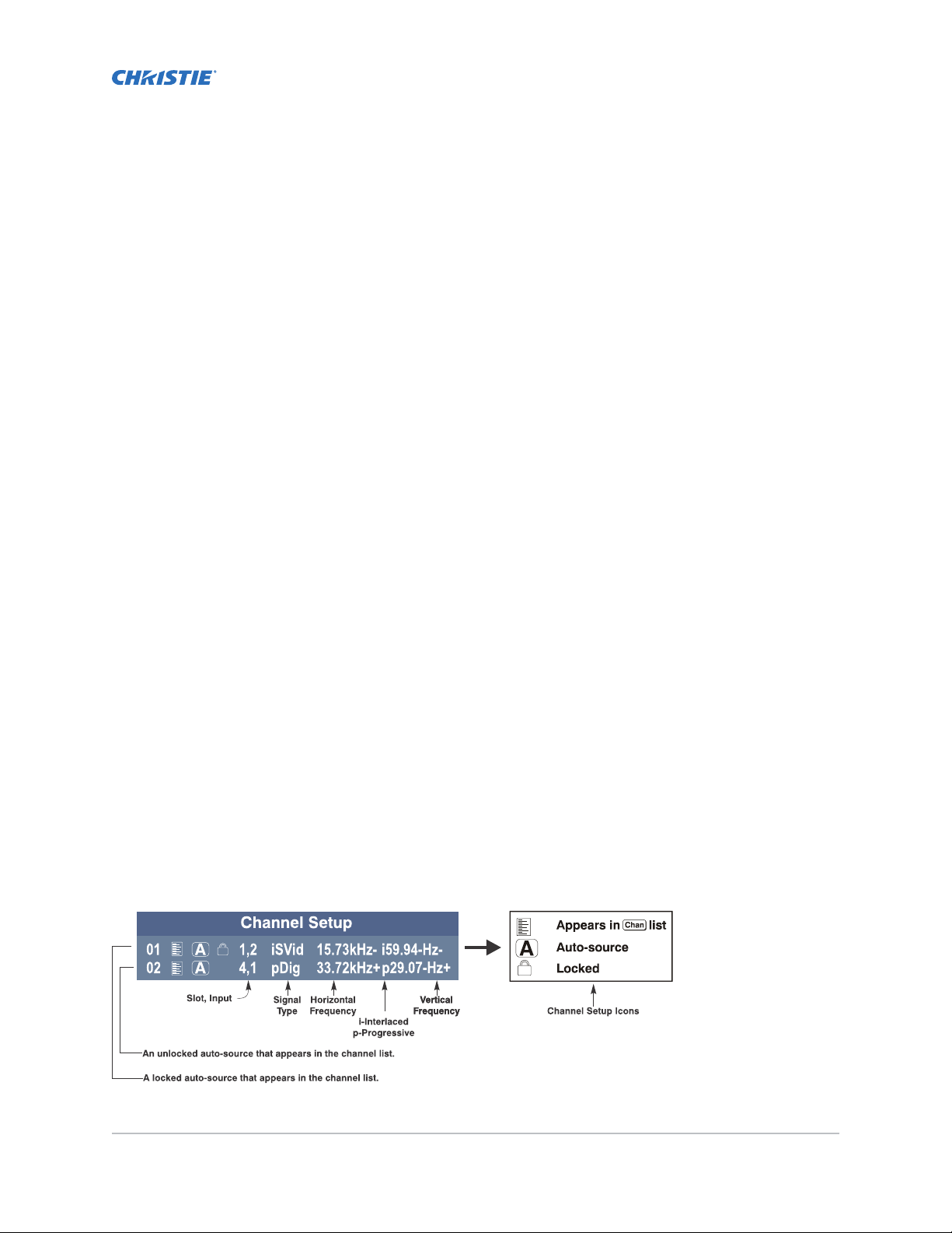
Displaying a list of channels
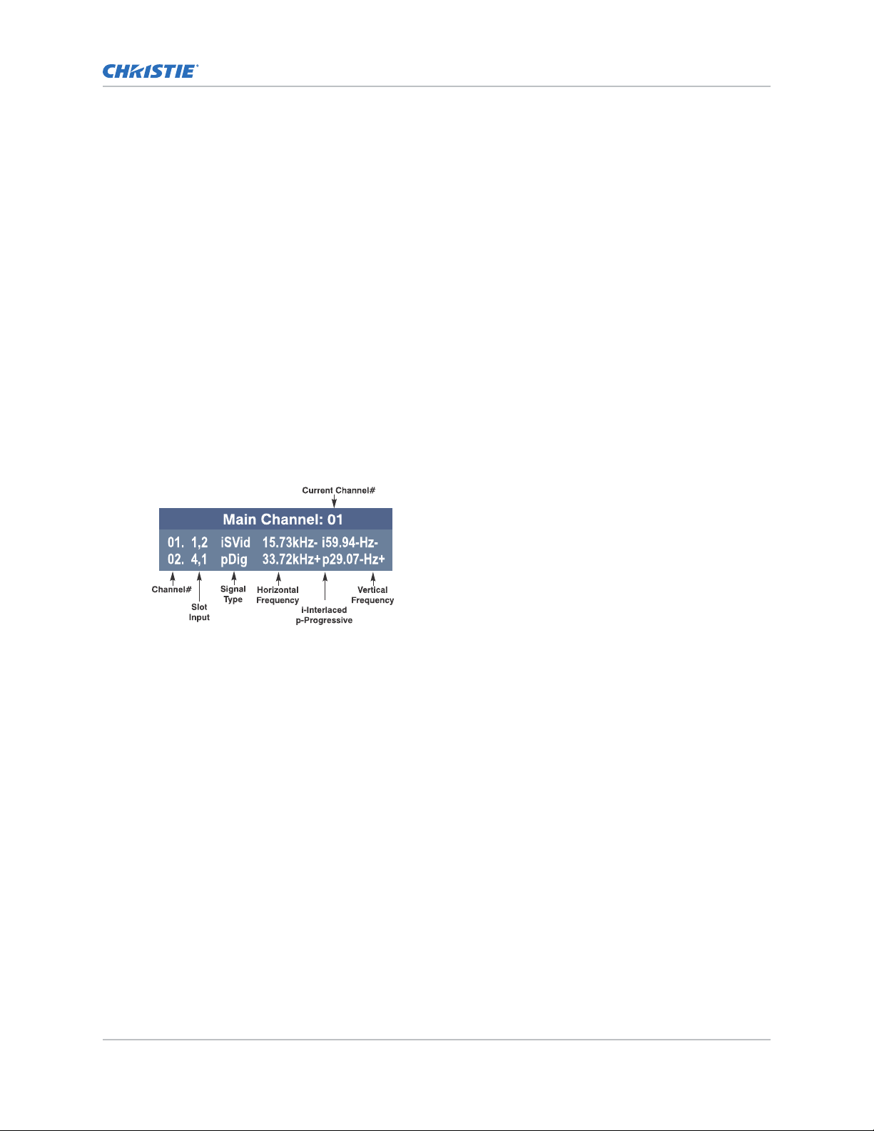
All available channels are listed in the Channel Setup menu, which describes how each channel can be
accessed and provides access for editing, copying, and deleting channels.
The channel setup icons list all defined channels. The far left column lists channel numbers defined.
The values in the far right columns indicate horizontal and vertical frequencies or if there is a defined
name for a channel, it appears here. The H and V frequencies do not appear if a name has been
defined for the channel; instead the name is only seen. The H and V frequencies are inserted as, the
name when the channel is first created. The vertical frequency is displayed with the sync polarity. The
remaining columns pertain to each signal type; such as, input number, slot location, a variety of icons
indicating access to each channel, and an abbreviated description of each signal type.
The channel list or the Channel Setup menu identifies signal types abbreviations as defined in the
following table. Composite Sync on the H/C input or the V input (four-wire). These abbreviations are
preceded by either an i (interlaced signals) or p (progressive signal).
M Series User Guide 23
020-101948-02 R
Copyright © 2018 Christie Digital Systems USA, Inc. All rights reserved.
ev. 1 (08-2018)
Page 24
Managing channels
The first five items in this table are analog RGB with various sync combinations indicating Sync Source
when editing the channel:
Abbreviation Signal types
— No Sync
4WH Composite (four wire) on HC input
4WV Composite (four wire) on V input
SG Sync-on-green (four wire)
5W Separate H,V (five-wire)
5WR Separate H,V swapped (five-wire)
SVid S-Video
CVid Composite Video
Dig Digital
DSDI Digital Dual Link HD-SDI
DVI Digital DVI
HDMI Digital HDMI
HSDI Digital HD-SDI
SDI Digital SDI
3GA Digital 3G-SDI (Level A)
3GB Digital 3G-SDI (Level B)
DP DisplayPort
1. To display the Main menu, press Menu
from the presentation level.
2. To display the Channel Setup menu, press 3 or move the highlight to the Channel Setup option
and press Enter.
3. To see the remaining channels not visible in the initial display of channels, press the Up and
Down keys.
Creating a channel
To use a new source with the projector, a new channel must be created so that the projector responds
to an input signal from that source.
A new channel can be created automatically, or it can be copied from an existing channel and then
edited as necessary.
When you select a direct input (Slot 1, Slot 2, Slot 3, or Slot 4), any existing channels in the projector
are searched for matching input and signal parameters–this only occurs if Auto Source is enabled on
these channels. If no match to the incoming input signal is found in currently defined channels, a new
channel is temporarily created based on factory-defined defaults for this type of signal. The channel
number assigned is the lowest available number from 01-99.
Note the following:
M Series User Guide 24
020-101948-02 R
Copyright © 2018 Christie Digital Systems USA, Inc. All rights reserved.
ev. 1 (08-2018)
Page 25
Managing channels
• An automatic channel is discarded unless one or more of its parameters are changed and will
not appear in the channel list (see below).
•
If two channels have the same distinguishing source characteristics except for the reversal of
sync connectors (H-sync and V-sync, are switched), they are still defined as distinct channels.
• You cannot define a new channel without an incoming signal.
Selecting a channel
Learn how to select a channel.
1. Select a channel at any time by pressing Channel.
The current channel is highlighted in the channel list, or, if the current channel is hidden, the
first channel in the list is highlighted.
Channels created automatically do not appear in the channel list unless a parameter for the
channel has been changed.
2. To change to another channel, type the two-digit channel number or move the highlight to the
channel and press Enter.
3. To hide a channel from appearing in this list, edit the channel. Such a channel can still be
selected by entering its number as shown below.
Selecting an input
Learn the different methods for selecting an input.
o select an input, do one of the following:
T
• Press the INPUT key.
This displays a list of the four slots, with the card type and input signal type in each slot.
The currently selected input for the main image is highlighted. Scroll up or down through
the list and press ENTER to make a new selection. Press the INPUT key again to show the
list and allow the selection for the PIP/Secondary image. Repeatedly pressing the INPUT
key toggles between the main and PIP/Secondary image.
• Press the appropriate direct SLOT key to quickly display one of the inputs on the selected
slot to the main image. This does not bring up any menu selection, and is only applicable
for the main image.
• To select the source of the image for the main or PIP/Secondary image select Menu >
Input Switching and PIP > Main Input and Menu > Input Switching and PIP > PIP
Input.
The image is displayed according to the following:
M Series User Guide 25
020-101948-02 R
Copyright © 2018 Christie Digital Systems USA, Inc. All rights reserved.
ev. 1 (08-2018)
Page 26

Managing channels
• If it is the first time you have used the source/input (or if you used the input but did
not define a channel b
signal based on its frequencies and polarities, automatically displaying an image
according to default settings for that signal.
• In general, the image from the new source is as large as possible without losing its
aspect ratio. This and other default image settings depend on the incoming source.
• If you used the source once before and changed a display parameter, such as contrast
and V-Position, then a channel was automatically created and still exists in projector
memory. Using one of the input or slot keys automatically recall this channel, all its
setup parameters, and update the display accordingly.
• If more than one channel exists for the input, the image is displayed according to the
setup parameters for the first channel with matching characteristics.
y adjusting anything), the projector recognizes the new input
Copying a channel
Copy a channel to create a new channel with similar settings.
1. To activate the Select Channel Operation submenu, in the Channel Setup menu highlight a
channel and press Enter.
2. Select Copy and press Enter.
A new channel is created that is identical to original, which still remains, but it is identified with
the next available number from 01-99. If you change your mind and do not want to copy the
current channel, press Exit to cancel and return to the previous menu. Copying channels is a
quick method for creating numerous channels, each of which can then be edited and adjusted
for a variety of presentations in the future.
Editing a channel
Edit an existing channel when the parameters of the input device change.
1. To display the Main menu, press Menu.
2. To display the Channel Setup menu, press 3 or move the highlight to the Channel Setup option
and press Enter.
3. Select the channel to edit and press Enter.
4. Review or edit the following settings:
• Name—An alphanumeric label can be defined or changed here. Channel names can be up
to 12 characters in length. The default name is the horizontal and vertical sync
frequencies.
• Channel—A two-digit channel number can be changed here. If you enter a channel
number that already exists, a message appears indicating that this number is already in
use; assign a different channel number. You can define up to 99 channels.
• Slot—1-4, corresponding to which slot in the projector’s input panel the source is
connected.
• Input—1-6, corresponding to which input on the selected slot the source is connected to.
• In Menu—If checked (default, except for automatically defined channels with unchanged
parameters), this defined channel appears in the list available when Channel key is
pressed. If unchecked, the channel must be accessed through Channel on the keypad or
M Series User Guide 26
020-101948-02 R
Copyright © 2018 Christie Digital Systems USA, Inc. All rights reserved.
ev. 1 (08-2018)
Page 27

Managing channels
through the Auto Source function. On-screen display of the channel list is an option that
must be set in the Menu Preferences
menu.
• Auto Select—If checked, (default), the projector can automatically locate this channel
when an incoming input signal matches. If not checked, the projector can locate the
selected channel only when it is directly selected with Channel on the keypad; a change
in input signal does not result in a channel change.
• Locked—If checked, all of the image settings for this channel are locked. If unchecked
(default), all available image settings can be adjusted. You cannot use Auto Setup with a
locked channel.
• Previous—Channel Select this option to see or change Channel Edit settings for the
previous channel in the Channel Setup list.
• Next Channel—Select this option to see or change Channel Edit settings for the next
channel in the Channel Setup list.
Deleting a channel
Delete a channel when the settings for the input device are no longer required.
1. To activate the Select Channel Operation submenu, select Channel Setup, highlight a
channel, and press Enter.
2. To delete a single channel, highlight the channel, select Delete, and press Enter.
3. To delete all unlocked channels, select Delete Unlocked Only and press Enter.
4. To delete all channels, including those that are locked, select Delete All Channels and press
Enter.
5. In the confirmation dialog, click OK.
When deleting mutliple channels, the current channel remains but is redefined from projector
defaults.
M Series User Guide 27
020-101948-02 R
Copyright © 2018 Christie Digital Systems USA, Inc. All rights reserved.
ev. 1 (08-2018)
Page 28

Using multiple projectors
When working with more than two projectors, work left to right, top to bottom.
When an installation requires multiple projectors, use the RS232 serial ports to daisy chain the units
together and control the group with a single k
projector. In such a network, you can choose to broadcast commands to the entire group, or use the
Proj key as desired to limit responses to an individual projector.
Alternatively, you may want to add projectors to a hub on an Ethernet network. For additional
information, refer to M Series Installation and Setup Guide (P/N: 020-101941-XX)
Tiling an image over multiple screens
eypad or a computer/controller connected to the first
Image tiling allows a single input image to be displayed, spread over multiple screens, with each
screen displaying a fraction of the image.
The image is displayed by the m × n array of projectors, where m is the number of rows (1-3) and n
is the number of columns (1-3). This allows the following arrays to be set up:
1x2, 2x1, 1x3, 3x1, 2x2, 2x3, 3x2, 3x3
Projectors are numbered from left to right (left column = 1), and from top to bottom (Top row = 1).
1. Set the total number of rows and columns in the array.
This setting is the same on all the projectors in the arr
2. Set the relative location of the projector within the array by identifying the row number and
column number for each projector.
3. Enable Tiling.
ay.
Performing preliminary calibration
All primary colors in the projector are precisely set to pre-established values to ensure that overall
color performance is optimized and is as accurate as possible.
Lighting and other environmental factors may slightly change how these colors appear on the screen.
While the change is negligible in most cases, you may prefer to recover the originally intended color
performance before trying to match colors from several projectors.
M Series User Guide 28
020-101948-02 R
Copyright © 2018 Christie Digital Systems USA, Inc. All rights reserved.
ev. 1 (08-2018)
Page 29

Using multiple projectors
In a multiple-projector wall, you want to precisely match color and intensity from image-to-image so
that the full w
1. To achieve consistency use a color meter to measure the native primary colors (red, green,
2. In the Service menu for each projector, record these as Color Primary Settings.
3. To return the primaries to the factory-set color, in the Service menu select Color Primaries >
4. Repeat the calibration process and continue with matching of colors.
all is as uniform as possible.
blue, and white) as they appear at the screen.
On the basis of these new values, which are stored in memory, each projector then
automatically calculates any necessary corrections to reproduce the original factory colors
under the current environmental conditions. This calibrates a projector to its surroundings,
compensating for factors such as screen type, lamp and/or ambient lighting, and improves
color accuracy and consistency in a group of projectors. It ensures a good starting point for
further customizing and matching; however, is not critical for all installations.
Reset to Factory Defaults.
Automatically correcting frame delay issues in tiled images
Frame delay compensation attempts to automatically correct for frame delay issues which may occur
in three row tiling.
When enabled, and using three row tiling, the manual frame delay control is disabled.
The features that act differently when Tiling is enabled are:
• The picture-in picture border is disabled.
• Cascading menus are turned off.
• Menus show only five items, with a scroll bar to allow the rest of the menu items to be
reached.
• Projector source switching in the array is not synchronized. Therefore some latency can be
seen from when the commands are issued to each projector, causing switching to not be as
seamless when in a tiling configuration. When using loop-through with the twin HDMI input
card to distribute a signal to the tiling array, additional latency in the switching can occur
during HDCP repeater negotiations with the source player.
1. To clear tiling settings, press FUNC+HELP.
2. Enable tiled warps and keystones through Christie Twist.
Refer to the Christie Twist User Manual (020-101380-XX).
Refining the displayed colors
In a multiple-projector wall, match color and intensity from image-to-image as precisely as possible so
that the full wall is uniform.
Once the Color Primary Settings are calibrated for the site, use the Color Adjustments by X,Y or Color
Saturation menu to further refine each projector’s fundamental colors so that the hue and intensity of
each color appears the same from one display to another. Once matched, you have created a single
new shared range of colors or color gamut that all of your projectors can produce. This palette—
M Series User Guide 29
020-101948-02 R
Copyright © 2018 Christie Digital Systems USA, Inc. All rights reserved.
ev. 1 (08-2018)
Page 30

Using multiple projectors
named User 1, 2, 3 or 4—can be applied or disabled for a source at any time throughout a bank of
adjacent displa
ys, simplifying both the setup and maintenance of a seamless wall.
1. Set up and optimize all projector settings.
You can ignore color temperature, since you are redefining color performance in this
procedure, but do optimize each projector in every other aspect. Closely align all screen edges.
2. Assign projector numbers to make communications easier.
3. Use the same lamp mode for all projectors, and do the following:
a) Set Select Color Adjustment to Max Drives.
b) Display a full white test pattern.
c) Adjust lamp power and optical aperture until adjacent white fields appear the same
brightness.
d) Display the Color Adjustments by X,Y menus for all projectors.
Each menu shows the x/y coordinates defining the Max Drives color gamut for this
projector.
e) Record the color adjustment values from one projector.
4. Create a User color adjustment for the other projectors in the array using the color adjustment
v
alues recorded in step 3e.
5. In each projector, adjust x/y coordinates slightly.
• To match reds, decrease Red X until full field red screens match.
• To match greens, decrease Green Y until full field green screens match.
• To match blues, increase both Blue X and Blue Y until full field blue screens match.
M Series User Guide 30
020-101948-02 R
Copyright © 2018 Christie Digital Systems USA, Inc. All rights reserved.
ev. 1 (08-2018)
Page 31

Using multiple projectors
For speed, enable Auto Color Enable. Each color coordinate selected automatically
triggers a full field displa
y of the corresponding color.
Alternatively, use the Color Saturation menu for these adjustments or to fine tune.
These coordinate adjustments move the three color points closer together to establish a
shared gamut attainable by all projectors in your group. Adjust only as necessary to ensure
that the resulting color palette is as large as possible. When done, lamp power may need to be
adjusted.
All screens should now be color-matched. Apply the new user gamut to a source at any time
by selecting it in the Select Color Adjustment list accessed in the Advanced Image Settings
menu.
Matching colors across multiple screens
In a multiple-projector wall, precisely match color and intensity from image-to-image so that the full
wall is as uniform as possible.
1. In the three Color Adjustment submenus (Red, Green, Blue, and White), set all main values to
1000 and the secondary values to 0, if applicable.
2. Adjust the slide bars as needed.
Adjustments here define new x/y coordinates in the Color Adjustments by X,Y menu. For best
results, use this menu after doing the color adjustment procedure.
M Series User Guide 31
020-101948-02 R
Copyright © 2018 Christie Digital Systems USA, Inc. All rights reserved.
ev. 1 (08-2018)
Page 32

Displaying picture-inpicture
Use the Input S
(PIP).
To control the primary image, access all picture controls through the Main menu. To control the
secondary (PIP) image, access picture controls through the Input Switching and PIP menu. PIP
function is disabled in 3D mode.
witching and PIP menu to enable and define how you want to use Picture-in-Picture
Enabling picture-in-picture
Learn how to turn on picture-in-picture mode.
1. On the remote, press PIP.
2. Toggle between displaying two sources at once (Main and PIP images) and the primary or main
source only.
This check box turns the secondary source on and off.
Selecting the main and picture-in-picture inputs
Learn how to select a PIP signal source.
1. Select Input Switching & PIP.
2. From the list of active inputs, select one to be used as the primary or main image.
3. From the list of active inputs, select one to be used as the secondary or PIP.
4. Toggle the current PIP relationship so that the primary (main) image becomes secondary (PIP),
and the secondary image becomes primary.
Swapping is available only when PIP is enabled. You may experience a slight delay when
swapping the Primary and Secondary images.
Configuring the picture-in-picture image
Configure the location and behaviour of the PIP image.
1. To set the location of the PIP (secondary) image in the display, select Input Switching &
PIP > PIP Windows.
2. To configure the PIP image, select Input Switching & PIP > PIP Image Settings.
3. To set the amount of time (in seconds) it takes to fade between images on a source switch and
fades in the PIP image, select Input Switching & PIP > Fade Time.
M Series User Guide 32
020-101948-02 R
Copyright © 2018 Christie Digital Systems USA, Inc. All rights reserved.
ev. 1 (08-2018)
Page 33

Locking image frames to the input
Displaying picture-in-picture
When the selection is set to Fr
the output is always locked to the primary input, never the secondary image.
1. Select Configuration > Option Card Settings.
2. To set the output to close at 60Hz for all sources, select Free Run.
Seamless switching is only available when free run is selected. When switching to a new input
with frame locking enabled, the image is black for the short period while the system locks onto
the new input.
ame Lock, output image frames are locked to the input. When locked,
Automatically searching for input signals
Configure the behavior when no signal is found for the picture-in-picture.
1. Select Input Switching & PIP.
2. To continually search for the next valid signal when no signal is present or when loss of sync
occurs on the current user selected input, enable Auto Input Switching.
In the case of multiple signals to choose from, the order is based on slot, followed by inputs on
that slot.
M Series User Guide 33
020-101948-02 R
Copyright © 2018 Christie Digital Systems USA, Inc. All rights reserved.
ev. 1 (08-2018)
Page 34

Adjusting the image
Learn how to adjust image geometry so it displa
The most commonly used options for image adjustments are accessed through two menus: Size and
Position (Menu 1) and Image Settings (Menu 2), both of which appear in the Main menu. From
either of these two menus, you can change settings affecting the image from the current channel by
working with the appropriate slide bars, check boxes and pull-down lists. Exit returns to the previous
menu (or to the presentation, if from the Main menu) and accept any changes you may have entered.
Settings are saved with the current channel.
Access any of the individual options in these menus by pressing Menu followed by the appropriate
two-digit number representing their location in the menu system. For example, press Menu 24 to
quickly access the Color Space option in the Image Settings menu.
For certain options, preference may be to use a direct key from presentation level to go directly to a
particular option without traveling through the menu system (available for certain display parameters
only). For example, press Contrast to access the “contrast” slide bar immediately. Press Exit to return
to your presentation.
To hide direct slide bars, disable the Display Slide bars check box in the Menu Preferences menu.
To hide the entire menu system from view, turn off the on-screen display by pressing OSD then the
Down Arrow Key.
ys correctly.
Automatically optimizing display parameters
Automatically optimize critical display parameters such as size, position, and pixel tracking based on
the type of incoming source.
The best auto setup is obtained under the following conditions:
• Input levels, it is best to have an image with saturated (very Bright) colors.
• Phase, high contrast edges are needed.
To determine active window size:
• Video images should have whites and blacks in the image
• Wide range video images should have content (including white) that extends to all edges of the
image.
All digital and decoder option cards do not present an additional auto setup menu since digital
hardware provides enough information to perform the correct auto setup.
Analog PC graphics sources (four/five-wire sync) present a list of formats based on the current active
lines detected in the video.
Analog Video Sources (three wire sync on green) always have the options Default and Advanced.
Video sources use a look up table to determine their format based on video standards. The Advanced
auto setup selection measures the start pixel and start line whereas Default uses the table values as
is.
To start the optimization, press Auto.
In some cases for analog video a menu may appear that presents multiple choices that allows
the user to select the format that best suits their source. This selection helps the auto setup
M Series User Guide 34
020-101948-02 R
Copyright © 2018 Christie Digital Systems USA, Inc. All rights reserved.
ev. 1 (08-2018)
Page 35

Adjusting the image
get the correct settings for the tracking and phase controls for analog sources that contain the
same number of activ
e lines, but have a different aspect ratios.
Displaying a test pattern
Display a test pattern to refine and adjust the projected image or diagnose and correct image issues.
1. To display a test pattern do one of the following:
• Press the Test key on the remote keypad.
• On the built-in keypad, press the soft key that displays Test on the LCD display.
• In the web user interface, select Configuration > Geometry and Color > Test Pattern.
2. Select a pattern appropriate for analyzing image focus and geometry, such as the Grid test
pattern showing the cross-hair centered across the image.
Changing the size and position of the image
Increase or decrease the size of your image, change its proportion (aspect ratio), move the image to a
specific area of the screen, and refine other related parameters.
Use Size and Position controls to match the image precisely to the screen used at the site. Changes
made in the Size and Position menu are applied immediately and are saved when you exit the menu
(press Exit or Menu).
Resizing the image with a preset
The same resize presets are available to all HD and SXGA+ screen models. However, the graphics
used to describe each preset in this section are of the SXGA+ models only.
Resize Presets displays an image in its native resolution (no resizing) or resizes the image by
maximizing either the height, width, or both height and width, or resizes to the maximum size
possible while keeping the original aspect ratio.
Size, Position, and Blanking parameters automatically adjust accordingly or, if Blanking is set first,
defines an active input area; Resize Preset scaling occurs in this region of interest only.
By default, when displaying a new source your image uses as much of the display area as possible for
the type of incoming source data, but with minimal or no changes to aspect ratio.
The custom re-size descriptor automatically appears in the Size and Position menu when any of the
values for Size, Vertical Stretch, H-Position, V-Position or Blanking do not correspond to those for a
preset. This option is not offered in the Resize Presets list.
1. Select Size and Position.
2. Select a resize preset.
• Default—Centers the image and displays it as large as possible, depending on the type of
source.
M Series User Guide 35
020-101948-02 R
Copyright © 2018 Christie Digital Systems USA, Inc. All rights reserved.
ev. 1 (08-2018)
Page 36

Adjusting the image
• No resizing—Displa
ys the image in its native resolution, which may or may not match the
resolution of the projector. For example, for a source with a native resolution of 800 x 600,
No Resizing in an SXGA+ projector uses the central 800 x 600 pixels and have a black
border. The black border areas are unused areas.
• Full size—Uses all pix
els for displaying the image, regardless of source or original aspect
ratio. Incoming source material having a different aspect ratio than the projector is
stretched for display.
• Full width—Fills the displa
y from left-to-right without changing the original aspect ratio of
the image. Depending on the source, data at the top and bottom may be discarded
(cropped), or the display may have black borders at the top and bottom (called “letter
boxed”).
• Full height—Fills the displa
y from top-to-bottom. Depending on the source, this may
create borders.
• Anamorphic—Displa
ys an anamorphic image in its native 16:9 aspect ratio. The image
fills the screen from side-to-side and be centered between black bars at top and bottom.
Resizing and positioning the image
Change the siz
1. Select Size and Position.
2. To control both the image width and height in tandem, maintaining the current aspect ratio of
the displayed signal data, adjust the Size.
e and location of the image.
M Series User Guide 36
020-101948-02 R
Copyright © 2018 Christie Digital Systems USA, Inc. All rights reserved.
ev. 1 (08-2018)
Page 37

Adjusting the image
3. To change the height of the image while keeping the width constant, altering the aspect ratio
of the displa
y, adjust the Vertical Stretch.
4. To move the image right or left within the area of available pixels, adjust the H-Position.
The value shown represents where the approximate center of the image lies in relation to the
total number of pixels available horizontally. This varies widely according to the signal; watch
the image while adjusting.
5. To move the image up or down within the area of available pixels, adjust the V-Position.
The value shown represents the approximate center of the image in relation to the total
number of pixels available vertically. This varies widely according to the signal; watch the
image while adjusting.
6. To ensure that auto setup for any source maintains the input aspect ratio when the default size
is calculated, select Keep Aspect on Auto Setup.
If disabled and the source is not a special case video source where a default stretch is defined,
the source is scaled to fit the platform.
7. If the display has steady flickering or several soft vertical stripes or bands across the entire
image, adjust the Pixel Track.
Proper pixel tracking ensures that the image quality is consistent across the screen, the aspect
ratio is maintained, and that the pixel phase can be optimized. Tracking determines the
frequency of the pixel-sampling clock, indicated by the number of incoming pixels per line, so
that all pixels generated by a particular source are sampled. By default, the projector samples
at the correct frequency for most sources.
For best results, use a test pattern such as a smooth grey consisting of a clear pattern of black
and white pixels, or a similar half on, half off graphic image, such as the Windows 2000
shutdown screen. Adjust the slide bar until the vertical stripes broaden to the point where one
large stripe fills the image.
8. If the image shows shimmer or noise after pixel tracking is optimized adjust the Pixel Phase
until the image stabilizes and each pixel is clearly defined.
You may notice that you can stabilize the image at more than one point.
Pixel phase adjusts the phase of the pixel-sampling clock relative to the incoming signal.
If some shimmer from a video or HDTV source persists, use the Filter control to remove highfrequency noise from the signal.
Cropping an image
Blanking defines the size of the active input window, or area of interest, and crops the image so that
unwanted edges are removed from the display and changed to black. The range of adjustment
depends on the source resolution and other factors.
1. Select Size and Position > Blanking.
The Active Input Window value indicates the current size of your displayed data or region of
interest as defined by the blanking controls. By default, the projector automatically determines
what portion of its full resolution to use, and pixels in the surrounding borders are turned off.
M Series User Guide 37
020-101948-02 R
Copyright © 2018 Christie Digital Systems USA, Inc. All rights reserved.
ev. 1 (08-2018)
Page 38

Adjusting the image
Blanking a picture-in-picture (PIP) image resembles zoom. For example, left Blanking zooms
the right side of the PIP image; Right Blanking z
ooms the left side. There are no black bars.
2. To specify a specific active input window size, adjust one or more Blank settings.
For example, if you have blanked (cropped) 100 pixels from both the left and right edges of an
incoming source of 1400 x 1050, the remaining active input window is reduced to 1200 x
1050.
Correcting a keystoned image
Keystone is typically caused by tilting the projector in relation to the screen so the lens surface and
screen are no longer parallel to each other.
Vertical keystone is used to correct a keystoned image shape in which the top and bottom borders of
the image are unequal in length, and both sides of the image are inclined toward the top or bottom
edge.
Horizontal keystone is used to correct a keystoned image shape in which the left and right borders of
the image are unequal in length, and the top and bottom are slanted to one of the sides.
M Series User Guide 38
020-101948-02 R
Copyright © 2018 Christie Digital Systems USA, Inc. All rights reserved.
ev. 1 (08-2018)
Page 39

Adjusting the image
Brightness Uniformity, Edge Blending and Black Level Blending should be disabled before performing
K
eystone adjustments.
Under certain combinations of extreme keystone coordinates and specific signal frequency, a
keystoned image may result that is outside the bandwidth limitations of the projector. When
attempting to apply the keystone settings, a message appears on the on-screen display, indicating
that the bandwidth has been exceeded and the keystone cannot be applied. The cursor co-ordinates
for keystone adjustment remains at the failed keystone position. This allows the user to make minor
changes and attempt to reapply the corner settings. Either the co-ordinates must be adjusted, or the
free run frequency must be changed to fall within the allowed bandwidth.
The Func+Help key combination immediately disables the Keystone, Brightness Uniformity, Edge
Blending, and Black Level Blending features. This is helpful when, in some extreme keystone
configurations, some image corruption may appear and/or the menus may not be readable. Although
Func+Help disables these features, it does not overwrite their settings. If keystone is enabled again,
the same image corruption may occur. After pressing Func+Help, Christie recommends immediately
resetting Keystone settings, which sets all keystone co-ordinates to zero.
1. Enable keystone adjustments by selecting Geometry Correction > Keystone.
This enables the controls for performing 1D or 2D keystone adjustments.
2. Select a test pattern.
Christie recommends using the grid test pattern.
3. Use the left and right arrow keys to change the Horizontal or Vertical Adjust settings and
perform coarse keystone adjustments.
The corner cursors are a guide as to how the image needs to be adjusted. The outside edge of
a cursor is the outside edge of the image. It may not be possible to exactly match the screen
dimensions with the horizontal and vertical keystone controls, but these settings can be refined
when the 2D keystone settings are adjusted.
4. When adjustment of the corners is complete, click OK.
A message is displayed indicating that the projector is processing the request and the settings
are applied to the displayed image. If vertical keystone adjustments have been made, starting
to do any horizontal keystone adjustments erase the vertical settings, and vice versa.
5. After the horizontal or vertical adjustments have been made, to retain the settings select 2D
Keystone adjustments.
6. Make fine adjustments by adjusting any single corner separately.
a) Use the arrow keys to move to the required corner.
The current corner is displayed in red.
b) To select the corner, press Enter.
The current corner is displayed in green.
c) Use the arrow keys to move the selected corner to match the screen.
d) To save that position for the corner press Enter again.
e) To adjust all four corners until they match the screen, repeat steps 6a to 6d.
7. To apply the new corner positions to the image select OK.
M Series User Guide 39
020-101948-02 R
Copyright © 2018 Christie Digital Systems USA, Inc. All rights reserved.
ev. 1 (08-2018)
Page 40

Adjusting the image
A message is displayed indicating that the projector is Processing request and the settings are
applied to the displa
8. To disable Keystone, Brightness Uniformity, Edge Blending, and Black Level Blending, press
Func+Help.
This is helpful when, in some extreme keystone configurations, some image corruption may
appear and/or the menus may not be readable. Although Func+Help disables these features,
it does not overwrite their settings. If keystone is simply enabled again, the same image
corruption may occur.
9. After pressing Func+Help, Christie recommends immediately pressing Reset Keystone
Settings, which sets all keystone co-ordinates to zero.
yed image.
Adjusting the main image
Alter the main image without affecting its size or position.
1. Select Image Settings and adjust the following:
• Contrast—Contrast increases or decreases the perceived difference between light and
dark areas of your image (0-100). For best results, keep close to 50. Start with a lower
value and increase so that whites remain bright but are not distorted or tinted, and that
light areas do not become white. If the environment lighting changes, an adjustment of
Gamma is recommended.
• Brightness—Increases or decreases the amount of black in the image (0-100). For best
results, keep close to 50. Start with a high value and decrease so that dark areas do not
become black. Conversely, high brightness changes black to dark grey, causing washedout images.
• Yellow Notch Filter—Yellow Notch Filer (YNF) is a channel based control with an
additional global control, which honors the last request. After enabling YNF, switching to a
channel that does not use YNF and the YNF filter is removed or disabled. Changes to the
global control affect the YNF filter.
• Color Space—Determines how the color components of an analog input signal are
decoded for accurate color in the display. Useful only for analog signals and certain digital
sources. Although color space for these analog signals is automatically determined by the
projector. You may wish to override this and manually set a color space. For some signals,
the color space function is entirely automatic and the list is disabled.
Changes made are applied immediately.
2. To save the changes, press Exit or Menu.
Configuring the video sources
Learn how to configure video sources.
1. Select Image Settings.
2. Select Video Options and configure the following:
• Enable Decoder (AGC)—AGC affects decoded video images only. Enter a check mark
(default) in most instances. Activate the decoder’s AGC circuit to ensure properly bright
images. Delete the check mark if a decoded video image exhibits strange color artifacts
such as stripes in highly saturated colors, indicating an incompatibility between this source
and the AGC.
M Series User Guide 40
020-101948-02 R
Copyright © 2018 Christie Digital Systems USA, Inc. All rights reserved.
ev. 1 (08-2018)
Page 41

Adjusting the image
• Video Standard—F
or most available video standards, the projector automatically detects
the incoming horizontal and vertical frequencies and sets the projector’s processing of this
signal to the corresponding standard. The current video standard name appears in the
Video Options submenu, and includes an A if it is auto-detected. To view or select a
different video standard from those available to the projector, press Enter; any that are
disabled have frequency characteristics that differ from those of the incoming signal.
Selecting a specific standard forces the projector to process the signal according to this
standard.
Best results are obtained with defined channels. Otherwise, switching from one video
source to another can sometimes cause slight disturbances in the display, indicating that
the Auto function is struggling. Recover by briefly selecting a different video standard,
then going back.
Standard Where used (subject to change)
Standard Where used (subject to change)
PAL Most of Europe, China, Australia, some of S. America, some of Africa
NTSC North America and Japan
SECAM France, Eastern Europe, most of Africa
NTSC 4.43 A tape-only standard for partially-translated hybrid signals
PAL-M Brazil
PAL-NC Argentina, Chile, other Latin American countries
PAL60
Note:
Generally, use Auto for all instances except a poor quality input signal or a black-and-white
video signal. To detect and display such signals, select the relevant standard from the list.
• Input Video Black—Compensates for incoming elev
ated black levels present in certain
video signals, and ensures that blacks in the display are neither crushed (where dark
greys appear black) nor excessively elevated (where blacks appear dark grey). By default,
the projector automatically determines the best setting according to the type of incoming
video signal:
• 0 IRE—Used for DVD output with enhanced black, SECAM, most PAL standards, and
Japanese NTSC.
• 7.5 IRE—Used for most NTSC video signals.
For some types of video, you can override the setting. The control is disabled for other
types of video and all graphics sources. Generally, if black appears crushed when
brightness is 50, choose 0 IRE. If black appears excessively elevated, use 7.5 IRE.
• Color—Adjusts the color saturation level. Lower settings produce less saturated colors, for
example a setting of 0 produces a black and white image. If the color level is too high,
colors is overpowering and unrealistic.
• Tint—Adjusts the red/green color hue for true color reproduction of video and HDTV
signals. For best results, adjust tint while displaying an external test pattern. It is
recommended that tint remain at its default setting.
• Filter—The proper filter setting is automatically set for virtually all signals, and rarely
needs to be changed. Override the only if standard pixel tracking and phase adjustments
do not adequately clear up a noisy video signal, or if a graphics signal appears overly soft.
Both instances indicate that Filter may be set to the wrong option.
M Series User Guide 41
020-101948-02 R
Copyright © 2018 Christie Digital Systems USA, Inc. All rights reserved.
ev. 1 (08-2018)
Page 42

Adjusting the image
• Sampling Mode—
Sets the color sampling mode for a digital signal to either YCbCr 4:4:4,
RGB or YCbCr 4:2:2. The proper sampling mode is determined automatically by the
projector; you can override this setting.
• Film Mode Detect—Enables or disables film motion detection. This is only available for
interlaced or segmented frame sources.
• Chroma/luma Delay—Affects any incoming composite or S-video signal, delaying the
luma signal (intensity) in relation to the chroma (color). In the image, increasing the luma
delay moves luma (seen as a shadow where colors overlap) to the right slightly, with
colors remaining in place. Decreasing this delay moves the shadow slightly to the left. If
necessary for your current source, adjust so that no shadows occur with adjacent colors.
• Split Screen—Allows a snapshot of the main image to be presented on the right side or
lower part of the screen for evaluation of advanced image processing features. All resizing
controls are honored on both images. However, image processing controls such as, Detail,
Sharpness, Noise Reduction and Adaptive Contrast only happen on the left side or top
image. Changing inputs, channels, or test patterns disables this control.
Split screen cannot be used in conjunction with either PIP or Tiling. Both PIP and Tiling
must be disabled prior to enabling Split Screen control.
• RGB Quantization Range—Defines the RGB quantization levels for digital DVI and HDMI
inputs using the RGB colors pace. Typically, graphics sources use the full range of levels
for the given bit depth (8-bit, 10-bit, 12-bit) and consumer electronics (CE) products
typically use a limited range of data within the given bit depth. This control must be set to
limited to correct the levels for those CE products that use the limited space. This adjusts
what is considered black and white levels in the image; for example for an 8 bit space, full
range RGB uses levels 0 (black) to 255 (white).
Manually optimizing input levels
Adjust the input levels of a source exhibiting overly high black levels, typically caused by a noisy
source causing black level spikes.
Because the projector automatically optimizes input levels for all but the most unusual of sources, we
recommend that only experienced users use the Input Levels submenu. Before beginning, check that
overall contrast and brightness settings are near 50 and that color temperature is properly set up on
an internal gray scale test pattern.
Good RGB or input levels—that is, the drives and black levels for each of the three colors, red, green
and blue—ensure that images from analog sources other than decoded video have maximum contrast
without crushing black or white. By default (and in an Auto Setup), the projector automatically
determines the best input levels by monitoring image content and adjusting the controls appropriately.
Further adjustment is typically not required to obtain proper blacks or whites. This automatic
adjustment requires at least 6-12 consecutive white pixels in the image. Without these pixels, input
levels may produce skewed colors, particularly in non-video images.
Input Levels are of limited use with digital signals, but do offer some ability to tweak poorly mastered
source materials. Input levels apply for the current source only, but for any color temperature used.
Assuming that color temperature has been set up based on the internal test patterns, you can then set
up input levels for a given source so that they match the color temperature of the internal test
patterns.
These adjustments, serve as a calibration process compensating for differences in sources and cabling,
to perfect the source image input levels and eliminate the overshoot and undershoot.
1. Select Image Settings.
2. Select Input Levels and change the following options:
M Series User Guide 42
020-101948-02 R
Copyright © 2018 Christie Digital Systems USA, Inc. All rights reserved.
ev. 1 (08-2018)
Page 43

Adjusting the image
• Auto Input Level—Compensates for incoming out
-of-range drives (white) and black
levels (black) that would cause crushing of light and dark colors in the image. After
entering a check mark, wait for the six slide bar values to stabilize, then delete the check
mark and exit. The Auto Input Level is automatically turned off upon exit from the Input
Levels Menu. Use only if you are an experienced user and you have an unusual source that
you feel needs further color temperature and/or input level adjustment.
• Black Levels And Drives—Do not use Input Levels to adjust color temperature. This
distorts contrast and brightness functions as well as color temperature.
a. Ensure overall Contrast and Brightness settings are set to near 50.
This is not required for Auto adjustment.
b. Check the color temperature setup using an internal grey scale test pattern, making
sure to obtain a neutral grey scale. This is not required for Auto adjustment.
c. Confirm that you are using input on an Analog BNC card or a Dual Link DVI card.
Input Levels are not applicable for sources going through the decoder. A grey scale is
recommended.
d. If black levels are too high (and/or whites are too low, which is rare), you likely have
a noisy source that is producing skewed input levels. In the Input Levels menu enable
Auto. Wait for all six values to stabilize. Alternatively, do not use Auto; reduce black
levels manually instead. Judge by eye and change one or more of the six levels as
necessary to obtain proper blacks and whites. You may want to see only a certain
color while adjusting; use the Auto Color Enable option.
e. Clear the Auto checkbox and leave the Input Levels menu.
• Auto Color Enable—When selected, setting a specific black level or drive to adjust
automatically enables the corresponding color in the display. To see all colors, clear the
checkbox or to enable a different specific color through the Color Enable control.
• Clamp Location—Brightens the image produced from certain high-resolution highfrequency graphic sources. The projector automatically selects the best clamp location for
most sources. Use the normal Back Porch location if the image is either sufficiently bright
or overly bright.
If the image appears unusually dim, has horizontal streaks across it, or has significant
color drift, select Sync Tip. This moves the clamping pulse from the normal back porch
location (which is likely too short) to the tip of the horizontal sync pulse. Tri Level is
typically needed for an HDTV source.
• Input Peak Detector—A tool to assist with defining individual input levels, enabling you
to accurately set the Input Levels for any particular source with the appropriate image.
Enabling the Peak Detector activates a special operating mode for detecting only pixels
that are considered black or white—all other levels are displayed as a mid-level grey.
When used with a smooth grey scale pattern in which black and white are known to be at
opposite edges of the image, you can watch these isolated areas while adjusting individual
black levels and input drives until both black and white edges are just visible and
distinguished from neighboring pixels. Images from this source display correct blacks and
whites without crushing.
a. Display a 16 level grey scale test pattern from the required external source, and
select Input Peak Detector.
The Input Peak Detector initially renders the grey scale as a uniform grey field before
adjustment or extreme crushing.
b. Display one primary color. To ensure the correct color is displayed for each setting,
select Auto Color Enable.
M Series User Guide 43
020-101948-02 R
Copyright © 2018 Christie Digital Systems USA, Inc. All rights reserved.
ev. 1 (08-2018)
Page 44

Adjusting the image
c. For the current color, adjust its corresponding Black level slide bar just until a single
band of black appears at one edge of the screen. This band represents the first band
of the grey scale pattern, which should be 100% black.
d.
With the same color still active, adjust its corresponding Input Drive slide bar just
until a single band of color appears at the opposite edge of the screen. This band
represents the last band of the grey scale pattern, which should be 100% white (or
the current color, if a certain color is enabled).
e. Check the black band and adjust the black level slide bar if necessary. Adjusting the
black levels affects the gain. Only adjust when necessary.
f. Repeat steps c and d for the two remaining primary colors. When each primary color
shows one optimized black band and white (or colored) band, the input levels for this
source are correctly set. Upon exiting the Input Levels menu, the Peak Detector check
box clears.
• Color Enable—Select which color or colors you want to see in the display, useful while
working with color temperature white levels or input levels.
Correcting gamma settings
Gamma correction can be applied to a specific source to correct for luma encoding.
The Gamma control provides settings per channel that are reapplied every time the same signal is
detected, as well as a global Gamma Correction control. The global control offers an offset applied to
all channels. This offset is used to compensate for changes in ambient conditions such as ambient light
in the room and projected material.
1. Select Image Settings > Advanced Image Settings > Gamma Settings.
2. Configure the following options.
• Gamma—Sets the base gamma table for a given source. Select from one of the standard
tables, a custom gamma function, or select an arbitrary gamma table that has been
downloaded to the projector. A separate PC utility is needed to do this.
The 2.22 curve is a power curve typically used to encode graphics and video sources. The
standard curve (auto setup default) is a modified 2.22 curve with a small linear section in
the black that enhances the detail in darker areas of the projected content.
Alternatively, if neither default is ideal, apply a simple gamma curve by defining a custom
power function and slope. For more complex non-standard gamma curves, a user-defined
curve created externally and downloaded to the projector can be used (requires separate
PC-based Arbitrary Gamma software application to create the table and the Web UI to
download it). If any of these special user curves have been installed, their names appear
in the Gamma Table pull-down list.
Select Gamma Function from the list to enable the Gamma Function and Gamma Slope
controls.
• Gamma Correction—Applies a global offset to all gamma settings for each channel. It
affects the shape of the curve by performing a linear transform toward a gamma curve of
1.0 while the control is increasing and likewise a linear transform toward a gamma of 3.0
as the control is decreasing. The control should only be adjusted to compensate for
ambient conditions. To correct a particular source only, use the Gamma control.
• Gamma Function—Defines the base gamma power curve used when the base gamma
table value is set to Gamma Function. This value, combined with gamma slope setting
determines the base gamma table used as the custom base table. The curve is generally a
power curve with a small linear segment at the bottom defined by the slope.
M Series User Guide 44
020-101948-02 R
Copyright © 2018 Christie Digital Systems USA, Inc. All rights reserved.
ev. 1 (08-2018)
Page 45

Adjusting the image
• Gamma Slope—Defines a slope to be used for the base custom gamma table for a small
section at the bottom of the curv
image.
e. This slope brings in or out the low level blacks in the
Adjusting the sharpness of the image
Setting detail above the halfway-point can introduce noise in the image. Lower settings can improve a
noisy signal.
This command does not take effect unless the minimum change required in the Detail Threshold
control is reached.
1. Select Image Settings > Advanced Image Settings > Detail.
2. Adjust the following settings:
• Texture Enhancement—Applies texture detail enhancement based on adaptive
horizontal, vertical, and diagonal large edge and small edge enhancement processes.
• Detail Threshold—Selects a filter sensitivity to noise. A higher value may improve noisy
sources especially for higher settings of detail.
• Detail Overshoot—Minimizes ringing on the enhanced edges detail and texture effects.
• Split Screen—Allows a snap shot of the main image to be presented on the right side of
the screen to allow evaluation of advanced image processing features. All resizing controls
are honoured on both images; however, image processing controls only happen on the left
side image. Changing inputs, channels or test patterns disable this control. PIP and Tiling
operation must be disabled prior to enabling this control.
Selecting the noise reduction filter
Improve noisy sources by applying a filter.
A higher value may improve noisy sources, but it soften the image.
1. Select Image Settings > Advanced Image Settings > Noise Reduction Settings.
2. Select a noise filter.
• Block Artifact Reduction—Locates and reduces block edges produced by discrete cosine
transform (DCT) based compression processing.
• Mosquito Noise Reduction—Reduces mosquito artifacts around sharp edges in DCT
based compression by dynamically adapting to image content.
• Split Screen—Allows a snapshot of the main image to be presented on the right side or
lower part of the screen for evaluation of advanced image processing features. All resizing
controls and input card features; such as color/tint etc, are honored on both images.
However, image processing controls such as the detail-texture, noise reduction and
adaptive contrast features, only occur to the left side image. Changing inputs, channels, or
test patterns disables this control.
Split screen cannot be used in conjunction with either picture-in-picture (PIP) or Tiling.
Both PIP and Tiling must be disabled prior to enabling Split Screen control.
• Full Screen Eye-motion Filter—Applies the Eye-Motion Filter to the entire screen, rather
than applying just to the edge blending.
• Eye-motion Filter—Reduces saccadic eye-motion artifacts, sometimes noticeable in edge
blending regions. Too much filtering may result in loss of detail. For best results, adjust
this setting while positioned at the nominal screen viewing distance.
M Series User Guide 45
020-101948-02 R
Copyright © 2018 Christie Digital Systems USA, Inc. All rights reserved.
ev. 1 (08-2018)
Page 46

Adjusting the color for the output
Adjusting the image
Customiz
e the output color.
1. Select Image Settings > Advanced Image Settings > Color Settings.
2. Select the output color adjustment most suited to this input signal.
• Max Drives—All color adjustments are turned off allowing the projector to run at
maximum brightness.
• Color Temperature—Sets a color temperature between 3200 and 9300 based on the
setting of the color temperature slide bar.
Expressed in degrees Kelvin [3200K, 5400K, and so on.]. Lower numbers appear reddish
white and higher numbers appear bluish.
Standard settings are:
• 9300K—Close to the white of many computer monitors
• 6500K—The standard for color video, in both standard and high definition forms
• 5400K—The standard for graphics and black and white video
• 3200K—Useful if the projected image is to be filmed or shot as part of a studio set
illuminated with incandescent lights
For all color temperatures the color primaries (red, green, and blue) are unchanged and
reflect the native colors of the projector.
• SD Video and HD Video—Sets the output color to a specific standard value. Adjusts the
red, green, blue, and white.
• User#—Select 1 of 4 user defined sets of color adjustments. The sets are defined in the
Configuration menu.
Related information
Defining user color gamuts (on page 47)
Selecting a color space
Determine how the color components are decoded for accurate color in the display.
1. Select Image Settings and press Enter.
2. Select a color space.
• Select RGB unless you are using component video.
• Select YPbPr (Video) with a standard definition televised signal (SDTV).
• Select YPbPr (HDTV) with a high definition televised signal (HDTV).
3. When certain RGB signals are first connected, the projector may not recognize them as RGB
and incorrectly decodes their color information as YPbPr (video). For these signals, change the
color Space to RGB, and then define a new channel for future use.
These signals can include:
• RGB signals in NTSC, PAL, SECAM frequency ranges.
• Scan-doubled sync-on-green.
• Scan-quadrupled sync-on-green.
M Series User Guide 46
020-101948-02 R
Copyright © 2018 Christie Digital Systems USA, Inc. All rights reserved.
ev. 1 (08-2018)
Page 47

Applying pre-defined color performance settings
Adjusting the image
The factory
projector, can be calibrated in the Service menu only.
1. Select Advanced Image Settings > Select Color Adjustment
2. Select a predefined color performance setting: Max Drives (default), SD Video, or HD Video.
3. To modify colors based on color temperature, select Color Temperature.
4. If the pre-defined settings do not suit your needs, define custom color gamuts.
5. To recover the factory settings, select Service > Color Primary Settings > Reset to
-defined primary color levels, which ensure a specific color performance from projector-to-
For most applications, one of these gamuts produce accurate and realistic colors from a variety
of sources.
Factory Defaults?.
Defining user color gamuts
If the pre-defined color performance settings do not suit your needs, define custom color gamuts.
For example, you may require a unique color gamut (range) for a single projector or application, or
you may need to precisely match colors across multiple adjacent displays.
Changing a color performance or gamut is sometimes known as Comprehensive Color Adjustment™.
Enter the known x/y coordinates from the chromaticity graph.
1. In the Color Adjustments by X,Y or Color Saturation submenu create, alter, or copy a color
gamut or color adjustment.
You can create up to four custom color gamuts (User 1, 2, 3, or 4) with these adjustments.
The two menus differ only in their user interface, so use whichever menu best suits your needs
and application. A color meter can help with adjustments.
2. Define the precise hue of each primary color component (red, green, blue, and white) used to
generate the millions of colors produced in displays.
3. To change the hue of the color, change either the x or y coordinates for each color and relocate
the triangle for possible colors.
Keep new x, y coordinates within the original color gamut triangle.
M Series User Guide 47
020-101948-02 R
Copyright © 2018 Christie Digital Systems USA, Inc. All rights reserved.
ev. 1 (08-2018)
Page 48

Adjusting the image
For example, changing the x/y coordinates for red may move the color closer to orange or
closer to violet, which in turn affects all displa
4. Adjust the slide bars or enter new specific coordinates as desired to define or change the color
gamuts.
5. In the Advanced Image Settings menu click Apply.
yed colors having a red component.
Adjusting the color saturation
If you do not have specific color coordinates in mind and judge color performance by eye or meter,
adjust the color saturation.
A Color Saturation adjustment defines the corresponding x/y coordinates shown in the Color
Adjustment by X,Y submenu. These x/y coordinates remain stable for this User gamut until they are
changed again through either menu. Values displayed in the Color Saturation menu fluctuate as you
use the projector, and is different when you return to this menu in the future. These floating changes
do not affect the x/y coordinates or gamut.
1. Select Advanced Image Settings > Color Adjustment.
Each color control defines new x/y coordinates for a color and changes its hue.
2. Adjust color slide bars and judge image color by eye or meter.
3. Adjust the hue of each primary color (red, green, blue, and white) by using more or less of it
in relation to the other colors.
Ensuring brightness uniformity
Use brightness uniformity to create an exceptionally smooth image in which no area appears brighter
than another.
Brightness uniformity provides further refinement of displays already matched for their primary colors
and overall light output.
When used to refine screens already matched for their primary colors and overall light output, proper
adjustment of brightness uniformity can create an exceptionally smooth screen in which:
M Series User Guide 48
020-101948-02 R
Copyright © 2018 Christie Digital Systems USA, Inc. All rights reserved.
ev. 1 (08-2018)
Page 49

Adjusting the image
• No area of the screen appears more red, green or blue than another
•
No area of the screen appears brighter than another
• Color and light output from one screen closely matches adjacent screens
Before you begin, read through the entire procedure before attempting to adjust Brightness Uniformity
controls, and keep in mind the following checklist of prerequisites and guidelines:
• Adjust Colors First—Always adjust the primary colors as described in Matching colors across
multiple screens on page 74 procedure, before attempting to work with Brightness Uniformity.
This ensures that primary colors, color temperature, and maximized light output are all well
matched from one screen to another. These matches are needed before you can achieve good
brightness uniformity results.
• Run Lamp For 100 Hours—Light output and brightness uniformity can vary significantly
during the first 100 hours of lamp use. For best results with new lamps, either set up
brightness uniformity after this period, or do an initial setup and re-check at 100 hours.
• Set Lamp Power—Ensure that each Lamp Power setting is as high as possible for your
application while still maintaining a good overall match of light output from screen-to-screen.
By nature, achieving a uniform brightness requires a slightly reduced overall brightness—this
reduction helps ensure that you have enough range of adjustment when examining brightness
variables more closely from screen-to-screen, and helps prevent premature maxing out when
trying to match to a certain color, zone, or projector.
• Use A user Color Temperature—Always adjust brightness uniformity for a User color
temperature defined when you matched primary colors, and continue to use it for all sources
displayed on the wall. Your other color temperatures will not necessarily be matched from
screen-to-screen.
• White Uniformity Slide Bars—White Uniformity slide bar values may not reduce to 0. Each
slide bar adjusts overall light output in a specific screen zone, but the value shown represents
the current setting for green in this zone. When other hidden values (red or blue) are lower
than green, during adjustment in the White Uniformity menu their values reach 0 first, causing
the slide bar to stop earlier than expected.
• Judge By Eye Or Use A Meter—Good brightness uniformity can be achieved with either.
Although the Brightness Uniformity control can be used for a stand-alone projector, it is particularly
useful for setting up and maintaining tiled images that form a cohesive display wall in which the color
cast and light output appear uniform throughout each image as well as throughout the entire wall. The
procedure provided here assumes a multiple-screen application.
1. To access a multitude of adjustments for light output control in specific areas throughout the
image, in the Brightness Uniformity menu, select Brightness Uniformity.
The settings apply as long as the Brightness Uniformity Enable check box is enabled.
To disable Brightness Uniformity, clear the Brightness Uniformity Enable checkbox.
2. To apply Brightness Uniformity settings with a large granularity, enable Coarse Adjustment.
Coarse Adjustment helps identify brightness changes and accelerates projector response time
while adjusting settings.
3. To ensure matched overall color temperatures and light output between screens, adjust
primary colors, double-checking that all whites and light output are well-matched.
4. Select the 13-Point test pattern for display, providing nine screen zones with 13 targets.
For best results, rather than examining the center of each zone when assessing Brightness
Uniformity adjustments focus on extreme edges.
M Series User Guide 49
020-101948-02 R
Copyright © 2018 Christie Digital Systems USA, Inc. All rights reserved.
ev. 1 (08-2018)
Page 50

Adjusting the image
5. In either Color Adjustments menu, select a User color. Then:
If you have created a “User 1” color gamut (recommended) for a well-matched wall,
•
continue to Step 6.
• If you prefer maximum brightness rather than a particular color temperature, select Max
Drives. Do not change User 1 Color Adjustment in color-matched applications.
6. In the White Uniformity menu, and set the overall output level to 50.0 and all remaining slide
bars to 0.0.
This decreases the light output just enough throughout the screen so that any color level can
then be increased later as necessary for matching light output from zone-to-zone. Do not
exceed 50.0 for Overall—a higher level likely interferes with achieving brightness uniformity
and is not recommended.
Ensure that overall light output remains well matched from one screen center to the next.
Where necessary, increase or decrease Lamp Power slightly to recover center matches.
7. On each screen, compare the color temperatures in the eight target zones (four edges and four
corners) to that of the color temperature of the center.
Compare using a white field only, and take note of any areas that do not match the center.
Also decide if any screen exhibits a more obvious color shift than other screens.
8. Beginning with the screen that exhibits the most obvious color shift(s), for each edge that
exhibits a noticeably different color temperature from the center, select the corresponding
Uniformity adjustment menu—Left, Right, Top, or Bottom.
For example, if any part of the left side is too blue, too red or too green, go to the Left
Uniformity menu and adjust the colors, for example change their light output, until all portions
of the left side closely match the center color temperature. Adjust an edge first (focusing on its
center), and then adjust the corners.
Repeat the color adjustment of sides and corners for each edge of the screen that does not yet
match the center (note that each corner is adjustable in either of its two adjacent side menus).
When done, all areas of a given screen should match.
9. Repeat steps 7 and 8 for all remaining screens.
10. Beginning with the screen exhibiting the most obvious variations in light output, compare the
light output of each edge and corner to that of the center. If any of the areas differ, use the
White Uniformity menu to match edges and corners to the center.
a) Adjust edge White Uniformity first.
Note that each edge adjustment also affects the rest of the screen slightly. Keep all edges
just slightly lower than the center light output rather than matching light output precisely.
Otherwise, it may not be possible to brighten the corners (typically the dimmest areas of
the screen) enough. The best uniformity is a compromise between the brightest and
darkest areas of the screen.
b) Adjust corner White Uniformity last.
M Series User Guide 50
020-101948-02 R
Copyright © 2018 Christie Digital Systems USA, Inc. All rights reserved.
ev. 1 (08-2018)
Page 51

Adjusting the image
Each corner adjustment affects only this quadrant.
c)
Repeat for each screen.
11. Repeat steps 7 and 8 and, if necessary, fine-tune the zones so that they all still exhibit a single
color temperature.
Related information
Matching colors across multiple screens (on page 31)
Creating a seamless image with edge blending
To blend overlapping edges together smoothly, use Edge Blending controls to set the precise width,
shape and midpoint.
Edge Blending provides a range of controls for smoothing together the overlapping bright edges of
multiple adjacent projected images to create a single larger seamless image. These controls, which
primarily affect white levels, are typically used in conjunction with mechanical lens blinders (optional),
which are installed on the front of the projector and which primarily affect black levels.
Brightness uniformity adjustment, if required, should be performed first. The Edge Blend or Grid Test
Pattern are useful for the mechanical setup of the projectors. If necessary, adjust Black Level Blending
first with the Black test pattern, then use the White test pattern to blend the white levels on the blend
edges. The final step is to check the blended image with an external source. The Edge Blending test
pattern has a center line (both horizontal and vertical). The intersection of these lines is the true
center of the projector’s display area.
In multiple-projector walls, complementary blends between neighboring images can compensate for
the extra brightness or intensity where these edges overlap. By controlling blend width and other
properties, you can achieve uniformity across the group of images. Visible overlaps disappears, as
shown below.
For best results, use the same projector model and type throughout your display wall. In addition,
avoid high-gain screens whenever possible—the optical performance of such screens demands minimal
image offset, thus projectors must be located very close to one another.
• Blend Width—Determines how much area is used for blending along an overlapping edge.
Slide bar values represent the number of pixel steps used for the blend. For example, a setting
of eight creates a blended edge eight pixels wide.
A setting of 0 signifies no blending. For best results in most applications, use a blend width
greater than 10% of the resolution of the projector (192 on a 1920 x 1080 projector). Larger
blend widths can mask uniformity issues between multiple projectors.
Ranges: (Projector number of columns / 2) horizontal, (projector number of lines / 2) vertical.
Example: 1920 / 2 = 960 pixels horizontal, 1080 / 2 = 540 pixels vertical.
• Blend Shape—Determines the rate of roll-off across the blend width, such as, how quickly the
white levels across the blend change from light and dark. Increasing the Blend Shape setting
accelerates the rate of change at both extremes so that less of the region appears mid-grey
(see Figure 3.20). Decreasing the Blend Shape setting slows the rate of change so that more
of the region appears mid-grey. For most applications, this subtle control is best left close to
50.
• Blend Midpoint—Determines the white level at the blend midpoint (the point equidistant
between the beginning and end of the blend). Increasing the Blend Midpoint setting creates
a blend that appears brighter than the rest of the image. Decreasing the Blend Midpoint
setting creates a blend that is darker than the rest of the image. A setting of 50 means the
midpoint is approximately 50% black—for best results in most applications, keep fairly close to
this default.
M Series User Guide 51
020-101948-02 R
Copyright © 2018 Christie Digital Systems USA, Inc. All rights reserved.
ev. 1 (08-2018)
Page 52

Adjusting the image
• Show Blending Overlap—
Turns your defined blend width area to solid grey so that, if
needed, overlapping the grey bars can seamlessly align two adjacent images. Toggle the Show
Blending Overlap off to reactivate the blend effect. Blending Overlap appears as Reserved
when Christie TWIST is installed.
Christie recommends the projector units be the same models and have identical part numbers. Before
attempting to work with edge blending software functions, align the projectors/images by correctly
overlapping the displays from your intended external source. Match colors and the brightness
uniformity. For a shared edge, all blend procedures and settings should be identical on both projectors.
1. Starting with two projectors, display a full white field test pattern from both.
2. Select Configuration > Geometry and Color > Edge Blending.
3. Enable Edge Blending.
4. Set starting points for adjustment:
a) Set all blend widths to 0.
b) Select More and set everything in the Edge Blending menu to 50.
5. Set blend width on one projector, increase the Blend Width for an overlapping edge (for
example, if the projector’s image is on left, its right edge overlaps the adjacent image—adjust
Right Blend Width). Use the same setting on the second projector for this shared edge.
6. Re-adjust the width on both projectors until the overly bright band at the midpoint of the
overlapping blends disappears or changes to very light grey. For the shared edge, use the
same Blend Width setting on each projector. If the best blend appears to be between two
settings, choose the wider setting for both projectors.
In applications where you are projecting only white or light images, the Blend Width may be
slightly higher—set according to how much overlap you have between images. Use the
following as a guide (examples show overlapping width only—values for overlapping height
differs). The recommended overlap is 12.5% - 25%.
7. Check blend if the blended region appears too dark or light in relation to the rest of the image.
a) Increase Blend Midpoint in both projectors to lighten the overall blend, decrease to
darken the overall blend.
b) Adjust Blend Shape in both projectors to fine-tune change the amount of mid-grey
intensity (as opposed to black/white) in the blend.
8. Repeat with remaining projectors with overlaps.
9. Check completed display wall with the desired external signal.
10. If necessary, adjust the mechanical alignment to maintain perfect pixel-on-pixel alignment
over time.
Adjusting the intensity of black
Eliminate the differences between black levels when edge blending multiple projectors.
The Black Level Blending submenu provides many controls to allow the edges of adjacent images to
be smoothly overlapped creating a seamless image. Adjust white levels before adjusting black levels.
Blinders are recommended for fixed installations.
Similar to Edge Blending, Black Level Blending allows you to adjust the black level intensity of
multiple adjacent projected images to create one large seamless display.
Adjust white levels before adjusting black levels. The zones in the Black Level Blending (BLB) menu
correspond to the edge blend zones.
M Series User Guide 52
020-101948-02 R
Copyright © 2018 Christie Digital Systems USA, Inc. All rights reserved.
ev. 1 (08-2018)
Page 53

Adjusting the image
1. Starting with two projectors, in the Geometry and Color
submenu, select the black test
pattern for both projectors from.
The menu options vary depending on the edge blending parameters. When adjusting six or
more projectors, you need to ensure that the brightness of each target area is matched at
closely as possible.
2. In the Black Level Blending submenu, enable black blending by selecting Standard from the
pull-down list for each projector.
3. Working with one projector at a time, use the center brightness slide bar to adjust the center
brightness (brightness of the non-blended region) so that the center intensity matches that of
the brightest blended region (the center of all images when blending a 2 x 2 display is the
target area).
4. Choose which of the next four options, Top, Bottom, Left, Right, to use depending on which
edge of the projector you are working with has been edge blended.
The blend width can be adjusted to line up properly but by default it corresponds to the edge
blending setting determined for that edge.
5. Adjust the brightness and black hues of the blended region in more detail in case fine-tuning is
needed.
This may be only necessary for blending a 2 x 2 projector display because of blending differs
for the sides and center.
Uploading a gamma file
Upload the gamma settings file to the projector for accommodating the ambient conditions.
1. Click Admin > System.
2. Click Upload Browse and locate and select the file on a Network drive location or from your
hard drive.
3. Select Gamma as the file type.
If you select a Gamma file type, it must be a .csv file with 1024 values (all colors same) or
1024 x 3 for individual colors to enable the Gamma Properties section.
4. To display the Gamma Upload window, click Upload.
5. Enter a descriptive name in the Display Name field.
6. To confirm the upload, click Yes.
M Series User Guide 53
020-101948-02 R
Copyright © 2018 Christie Digital Systems USA, Inc. All rights reserved.
ev. 1 (08-2018)
Page 54

Monitoring and maintaining the projector
Installers, service tr
at all times. Read through this section in its entirety and understand all warnings and precautions
before attempting to operate this projector.
ained operators, and all other users must maintain a safe operating environment
Backing up the configuration and preferences
You can back up the current projector settings in case you must restore these settings at a later time.
1. Click Admin > System.
2. Select a file type (All, Preferences, Configuration, Channels, or Users) from the Backup list.
3. To initiate the download click Backup.
A backup in progress bar appears. Once finished, a file download window appears.
4. Click Save.
5. Locate and select a folder within your Network drive or hard-drive where you wish to save the
file.
6. Click Save.
Restoring a backup file
Use the following instructions when importing and restoring the projector's settings from the saved
backup file.
1. Click Admin > System.
2. Click Browse.
3. Locate and select the file to restore.
4. Select the type of file to restore (All, Preferences, Configuration, Channels, Users or Real Time
Events (RTE)).
Do not select All unless transferring all files from one projector to another or cloning.
5. Click Restore.
A Restore in Progress bar appears. Once finished, a confirmation message appears.
M Series User Guide 54
020-101948-02 R
Copyright © 2018 Christie Digital Systems USA, Inc. All rights reserved.
ev. 1 (08-2018)
Page 55

Monitoring and maintaining the projector
Performing a diagnositic test using interrogator
un the interrogator to identify and correct projector faults.
R
1. Click Admin > System.
2. To initiate the diagnostic test and download the diagnostic test results to your computer, click
Interrogate.
A Interrogator in Progress bar appears. Once the download is complete, a File Download
window appears.
3. Click Save.
The results can be saved to a Network drive or local hard-drive.
Monitoring the projector status
The read-only Status menu lists a variety of details about the standard and optional components
currently detected in the projector.
Refer to the Status menu for versions of hardware and software installed, the type (size) of lamp, the
hours logged in total and for a specific period (such as a rental period), and for your projector model
name and serial number. In addition, the Status menu identifies the current channel, its location, its
frequencies and other details.
Alarm conditions
An alarm condition consists of a message that is on the LCD display located beside the built-in keypad.
There are two types of alarm conditions:
• Warning alarm—Appears when an error or a non-optimal condition has occurred, and generally
does not prevent the projector from operating. An example is when a temperature is slightly
elevated.
• Critical Alarm—Appears when a condition occurs that could prevent the projector from
operating and could cause damage to the projector. This may cause the projector to shut down
automatically. An example would be a fan not running.
Both alarm types display:
• The item of alarm
• The status of the item
The item of the alarm can be either physical (fan or sensor), or the alarm can be a software issue
(lamp driver). The LCD displays the status of the item and its units. If the status of the item is out of
normal range an alarm is created. When the status of the item is within normal range the alarm
clears.
When an alarm is displayed in the LCD display, the built-in keypad is disabled. To confirm the alarm,
press the OK soft key to enable the built-in keypad. The alarm condition can also be viewed in the
read-only Status menu using the remote.
M Series User Guide 55
020-101948-02 R
Copyright © 2018 Christie Digital Systems USA, Inc. All rights reserved.
ev. 1 (08-2018)
Page 56

Monitoring and maintaining the projector
Configuring SNMP
The
M Series SNMP (Simple Network Management Protocol) interface provides network administrators
with a common way to manage their network devices from a single remote location.
SNMP allows an administrator to query a number of devices to see their current status and
configuration. It also allows operators to change configuration values and configure trap notifications
to be sent when certain events occur.
1. Select Configuration > Communications > SNMP
2. Request the current state of the following controls.
• Power
• Main
• Input
• Channel
• Lamp Life
• Shutter
• Host Name
• IP Address
3. Request these status items directly.
• Main software version
• Global alarm status
• Lamp 1 life (just Lamp Life is displayed if there is no second lamp)
• Lamp 2 life (if applicable)
• Lamp 1 status (just Lamp Life is displayed if there is no second lamp)
• Lamp 2 status (if applicable)
4. Configure the SNMP traps.
A trap is a condition that SNMP monitors on the projector. When the condition is met, a
notification is sent by an SNMP notification or email message. Each traps condition can be set
to Disabled, SNMP Trap, Email or SNMP Trap + Email. The traps are defined in a series of
MIB files hosted directly on the projector. MIB files can be accessed from a web browser
window, using the address //<IP Address>/mibs/.
Operators are able to select from the following trap events to receive up to three SNMP traps
and three email notifications when they occur:
Event Message
(Email
Notification)
Lamp end of life Lamp has reached
end of life
Lamp end of life
cleared
Lamp fault Lamp fault has
M Series User Guide 56
020-101948-02 R
Copyright © 2018 Christie Digital Systems USA, Inc. All rights reserved.
ev. 1 (08-2018)
Lamp end of life
cleared
occurred
Parameters Trap Config.
Menu Text
Lamp Number
Lamp Hours
Elapsed
Lamp Number
Lamp Number
Lamp F
ault
Lamp Life SNMP Trap + Email
Lamp Fault
Default
Notification
Setting
Page 57

Monitoring and maintaining the projector
Event Message
(Email
Parameters Trap Config.
Menu Text
Notification)
Description
Lamp fault cleared Lamp fault has
been cleared
Fan stall Fan stalled Fan Name Fan Stall
Fan no longer
stalled
Thermal sensor
w
arning
Thermal sensor
error
Thermal sensor OK Thermal sensor OK
Projector powered
on (Standby to
Lamps On)
Projector powered
off (Lamps On to
Standby)
No video input
signal
Fan stall cleared
Thermal sensor
warning
Thermal sensor
error
Projector turned on
(lamps on)
Projector turned off
(lamps off)
No video input
signal
Lamp Number
Thermal Sensor
Name
Thermal Sensor
Text
None Power Disabled
Frequency Signal Lost/
Thermal Sensors
Detected
Default
Notification
Setting
Video input signal
detected
Lamp door open Lamp door has
Lamp door closed Lamp door has
Video input signal
detected
Lamp Number Lamp Door
been opened
been closed
5. Configure the Email notification.
When a tr
ap occurs while email notification is selected for the event, an individual email is sent
to each user defined email recipient. The SNMP menu allows up to three email address (up to
64 characters in length) to request notifications from the system during a trap event.
The resulting email is in the following format:
From: <from@email.com>
To: <to@email.com>
Subject: Christie
M Series Projector SNMP Notification
Message:
Projector Name: <projector name>
Location: <SNMP location>
IP Address: <IP address>
Description: <message>
Parameters: <param 1> = <param 1 value>; <param 2 > = <param 2 value>; ...
M Series User Guide 57
020-101948-02 R
Copyright © 2018 Christie Digital Systems USA, Inc. All rights reserved.
ev. 1 (08-2018)
Page 58

Adding a scheduled event
Monitoring and maintaining the projector
Scheduled ev
1. Select Advanced > RTE and click Add.
2. Select the Scheduled Event tab.
3. Select the frequency option for the event by selecting either Once, Daily, Weekly, or
4. To open a calendar pop-up window, click within the Start Time field.
5. Navigate to and choose a desired date.
6. In the field below the Start Time field, enter a start time in the format hr:min:sec.
7. To set the computer and projector time to be the same, click Sync; otherwise, the event runs
8. Enter a description of the scheduled event, with a maximum of 100 characters.
9. In the Command String box, enter a serial command or a sequence of serial commands for
10. Click Finish.
11. To activate or deactivate one or more RTEs, select or clear each check box in the Active column
ents include a command or sequence of commands.
The scheduled tab is always selected by default on add.
Monthly.
End Date is enabled when Daily, Weekly or Monthly repeat options are selected.
The selected date populates the Start Time field.
The default is the current time.
based on the projector time.
the projector to perform.
• If a GPIO command string is needed, click the GPIO Output Helper button for
instructions on how to create the command structure.
The Output field contains seven blocks which refer to the seven I/O pins on the GPIO
connector. Pin 1 = +12V and Pin 5 = Ground. These are not included. Clicking a block
toggles between H, L, and X. If the Pulse check box is selected, those I/O Pins defined
pulse high or low. The Serial Representation box is read only.
• For a description of special RTE commands available for adding loops and delays to the
command sequence click the Help button.
• To test the entered command string, click the Test button.
If the test passed or failed, a green or red icon appears to the right side of the Test button.
The added event appears in the RTE Listing window.
accordingly.
Adding a system event
Run a command when the specified system event is triggered.
1. Select Advanced > RTE and click Add.
2. Select the System Event tab.
3. Select a type of System Event.
M Series User Guide 58
020-101948-02 R
Copyright © 2018 Christie Digital Systems USA, Inc. All rights reserved.
ev. 1 (08-2018)
Page 59

Monitoring and maintaining the projector
Adding a GPIO event
R
un a command when the specified GPIO input is received.
1. Select Advanced > RTE and click Add.
2. Switch to the GPIO Event tab.
3. Define the Input Condition field as required for the GPIO Event.
The Input Condition field contains seven blocks, which refer to the seven I/O pins on the
GPIO connector. Pin 1 = +12V and Pin 5 = Ground are not included or changed. Clicking a
block toggles between H, L and X.
Adding a function key event
Run a serial command when the function key is pressed.
1. Select Advanced > RTE and click Add.
2. Select the Function Key Event tab.
3. Select a function from the list.
LED and key states
The LED color of the keys indicates that the key is in one of these states
LED color Status
Amber A functionality is available that affects the displayed image of the projector.
Blue A functionality is available that is relevant to the built-in LCD only and will not affect the
displa
yed image from the projector.
Off The key is disabled in the current context.
Power key Used to switch from Standby mode to ON, and from ON to Standby mode; LED always remains
Amber
Help key Only available in the on-screen display (OSD) context; LED is Amber when the menu is being
displayed on the projected image display. When no menu is being displayed, the Help key is still
enabled if the OSD is enabled. It is only disabled when the entire OSD is set to OFF.
Auto key Enabled state when the power is ON, and there are no test patterns on the screen. If the power
is OFF or a test pattern displays, the Auto key is disabled.
Exit key Is determined in the specific context of the screen being displayed.
Input key Enabled when the power is ON. Disabled if the power is OFF.
Lens key Enabled when the power is ON. Disabled if the power is OFF.
Shutter key Enabled when the power is ON. Disabled if the power is OFF.
Menu key Always remains in the enabled state when the power is ON. If the power is off the Menu key is
disabled.
Soft key Used to select an action indicated by text above the key on the LCD. If no text is shown, the
associated key is disabled.
M Series User Guide 59
020-101948-02 R
Copyright © 2018 Christie Digital Systems USA, Inc. All rights reserved.
ev. 1 (08-2018)
Page 60

Monitoring and maintaining the projector
Projector status LEDs
Identif
y the input LED state colors and meaning.
Looking from the back of the projector, the LEDs represent, from left to right; Lamp 1, Lamp 2, Power,
and Status. The LEDs display the colors as shown below.
Projector state LEDs LED state
Hard boot All All LEDs amber—Please wait
Standby mode Lamps 1 and 2 Off—Lamps are off
Power Amber—
Shutter Green—Shutter is open
Amber—Shutter is closed
Warm-up (Powering on
from standby)
Normal operation Lamps 1 and 2 Amber—Lamp time has expired and lamp should be replace
Cool-down All LEDs cycle from left to right
Error Lamp 1 and 2 Amber—Lamp time has expired and lamp should be replace
Software upgrade in
progress
Lamp Regeneration in
progress
All LEDs cycle green from left to right
Power Green—Projector is powered up and operating normally
Shutter Green—Shutter is open
Amber—Shutter is closed
Flashing red—Lamp time has expired and lamp should be replace
Power Flashing red—Error has occurred. Details are displayed on the
status display.
All The pattern will alternate between Amber and Off
Lamp 1 and 2 Flashing Green—The lamp is being switched off for its
regeneration period to extend lamp life (typically 15 minutes every
24 hours)
AC is present but projector is off or standby
Power Green—On
Amber—Standby
Shutter Green—Shutter is open
A condition occurs on the first power on after a software upgrade, and is indicated by all the following:
•
The Status LEDS are cycling green
• The LCD displays the warning Image Processor Upgrading
• The LED on the image processor card flashes green
• The web page shows a warning that the image processor card is upgrading
• When this occurs, the projector should not be AC power cycled and the image processor card
should not be removed
M Series User Guide 60
020-101948-02 R
Copyright © 2018 Christie Digital Systems USA, Inc. All rights reserved.
ev. 1 (08-2018)
Page 61

Monitoring and maintaining the projector
Maintaining the cooling system
The high-intensit
maintenance of the cooling system is critical to prevent overheating and sudden projector failure and
helps ensure reliable operation.
Caution! If not a
Notice. If not a
y lamps and electronics rely on a properly functioning cooling system. Regular
voided, the following could result in minor or moderate injury.
• Do not remove or disable the vane switch.
• Do not attempt to operate the product with inadequate airflow which can result in dangerous
overheating.
• Keep fingers and other body parts away from the moving parts in the product. Tie back long
hair, and remove jewelry and loose clothing before manually adjusting the product.
voided, the following could result in property damage.
• Use only high efficiency Christie approved filters.
• Do not reuse an old air filter.
• Do not operate the product without the filter installed.
Ventilation
V
ents and louvers in the projector covers provide ventilation, both for intake and exhaust.
Never block or cover these openings. Do not install the projector near a radiator or heat register, or
within an enclosure. To ensure adequate airflow around the projector, with a minimum clearance of
25cm (10”) on the left, right and rear sides of the projector from any walls or other obstructions.
Replacing the dust air filter
Complete this procedure to replace the dust air filter.
Check projector air dust filters, at minimum, every month.
Dust air filters must be replaced whenever the lamp is replaced or between 200-500 hours, depending
on use. A clogged air filter reduces air flow and can lead to overheating and failure of the projector.
Check monthly by inspecting its color through the side vent grille with a flashlight. Replace grey
colored filters.
Leave the filters in their sealed packaging until ready for use.
1. Unscrew the two captive screws at the top of each filter door. Allow the door to rest down and
away from the projector.
2. Slide the air filter out and replace, vacuum or wash the filter.
ash using mild soap and water. Dry the filter before using.
W
3. Insert the new or clean air filter.
M Series User Guide 61
020-101948-02 R
Copyright © 2018 Christie Digital Systems USA, Inc. All rights reserved.
ev. 1 (08-2018)
Page 62

Monitoring and maintaining the projector
4. Secure the filter door by tightening the two captive screws loosened in step 1.
Replacing the fog oil filter
Complete the following procedure to replace the fog oil filter
Fog filters should be replaced after each use of the projector to a maximum of 20 hours. The life of the
filter is approximately 20 hours based on environmental conditions. Leave the filters in their sealed
packaging until ready for use.
The fog filters cannot be re-used or they clog up with oil and the projector overheats and shuts down.
Each filter is a two-stage filter; the black activated charcoal layer faces out, and the white layer faces
the projector.
1. Loosen the two captive screws at the top of each filter door.
2. Slide the filter out.
Insert the new filter with the white layer facing into the projector and the black layer facing
3.
out.
4. Secure the filter door by tightening the two captive screws loosened in step 1.
.
Maintaining the optics
Inspect and clean optical components such as the projection lens or reflector to ensure optimum
image display.
Viewing the lamp history
Monitor the states of the lamps and the number of hours used.
To display the serial number and the number of hours logged for each lamp (currently and
previously) installed in the projector, select Lamp > Lamp 1 History or Lamp > Lamp 2
History.
The top-most entry is always the most recent/current lamp.
Notifying users after a set number of hours of lamp use
When the lamp has been used for a specified number hours, display a message.
1. Select Lamp > Warn when lamp reaches (hours).
2. Set the number of hours.
M Series User Guide 62
020-101948-02 R
Copyright © 2018 Christie Digital Systems USA, Inc. All rights reserved.
ev. 1 (08-2018)
Page 63

When set, the projector displays a warning message when the lamp has a recorded ON time
that ex
ceeds the specified number of hours. The warning is displayed on the status page for
each lamp, where applicable.
This setting is user-defined only. It has no bearing on lamp warranty and is not tied to actual
lamp life in any way.
3. To disable the notification, set the number of hours to 0.
Replacing the lamps
Follow these steps to install a new lamp in the projector.
Caution! If not a
• SHOCK HAZARD! Disconnect the product from AC before installing, moving, servicing, cleaning,
removing components, or opening any enclosure.
• EXPLOSION HAZARD! Allow sufficient time for the lamp to cool down before powering down the
product, disconnecting it from AC, and opening the lamp door.
• Dispose of bare bulb with packaging according to local area regulations.
• EXPLOSION HAZARD! Do not stress the glass of a lamp or bare bulb in any way.
• UV EXPOSURE! Protective UV safety glasses with side shields and Christie approved protective
safety clothing must be worn when performing optical adjustments or servicing the product.
voided, the following could result in minor or moderate injury.
Monitoring and maintaining the projector
Removing the lamps
The projector runs dual 200W
side of the projector from the intake air filters.
Warning! If not a
• UV EXPOSURE! Protective UV safety glasses with side shields and Christie approved protective
safety clothing must be worn when performing optical adjustments or servicing the product.
• EXPLOSION HAZARD! Allow sufficient time for the lamp to cool down before powering down the
product, disconnecting it from AC, and opening the lamp door.
1. Open the lamp doors by unscrewing the captive screw.
2. Unscrew the three captive screws securing each lamp.
, 350W, or 450W mercury lamps. Two lamps are located on the opposite
voided, the following could result in death or serious injury.
M Series User Guide 63
020-101948-02 R
Copyright © 2018 Christie Digital Systems USA, Inc. All rights reserved.
ev. 1 (08-2018)
Page 64

Monitoring and maintaining the projector
200W and 350W 450W
3. Slowly slide the lamp out of the compartment.
For the second lamp, repeat steps 1 to 3.
4.
5. Check the aluminum tape on the lamp door. If there are any signs of adherence degradation,
replace the tape.
Installing the lamps
If replacing lamps due to a lamp explosion; both lamps should be removed from the lamp housing
area, including fan #4 and exhaust ducts. Ensure they are carefully vacuumed before lamp
replacement.
Warning! If not a
• UV EXPOSURE! Protective UV safety glasses with side shields and Christie approved protective
safety clothing must be worn when performing optical adjustments or servicing the product.
voided, the following could result in death or serious injury.
1. Carefully insert the lamp into the lamp housing with the connector oriented to the top.
2. Seat the lamp onto the mating connector in the projector and push the lamp forward until fully
seated.
3. Secure the lamp with the three captive screws.
4. Close and secure the lamp door.
Disposing of the lamp
The lamp is extremely hazardous. Do not dispose of in regular trash.
For warranty claims:
1. Carefully repack the lamp with the original shipping material and carton.
2. Enclose the completed RMA claim form that came with the lamp.
3. Ship the lamp to the nearest Christie service depot for evaluation.
For safe disposal:
1. Pack the lamp into its original carton (without the packaging material).
2. Tape the box up securely along its seams.
3. Discard as industrial waste, in accordance with your local regulations.
M Series User Guide 64
020-101948-02 R
Copyright © 2018 Christie Digital Systems USA, Inc. All rights reserved.
ev. 1 (08-2018)
Page 65

Changing the lamp serial number
Monitoring and maintaining the projector
Change the serial number for the current lamp
The new serial number is applied to the current lamp statistics file. It does not archive the current
statistics as done by the Change Lamp function.
1. Select Lamp > Lamp 1 s/n or Lamp > Lamp 2 s/n.
2. Enter the new serial number.
.
Cleaning the projector optics
Learn about cleaning the optical components in the projectors.
Unnecessary cleaning of optics, increases the risk of degrading delicate coatings and surfaces. Only
clean optics when dust, dirt, oil, fingerprints or other marks are obvious and are causing performance
problems. Maintenance of optical components requires a qualified service technician. Inspect exposed
optical surfaces periodically in a clean, dust-free environment using a flashlight.
Never touch an optical surface with your bare hands. Always wear latex lab gloves.
Use the following products when cleaning the optical surfaces:
• Soft camel-hair brush
• Dust-free blower—filtered dry nitrogen blown through an anti-static nozzle.
• Dust-free lens tissue, such as Melles Griot Kodak tissues (18LAB020), Opto-wipes (18LAB022),
Kim Wipes or equivalent
• Cotton swabs with wooden stems only
• Lens cleaning cloth/microfibre, such as Melles Griot (18LAB024) or equivalent
Cleaning the lens
To avoid the risk of scratching the lens, clean the lens only if absolutely required.
Removing dust from the projection lens
Remove dust from the projection lens to ensure optimum image display.
1. Brush most of the dust off with a camel-hair brush or use a dust-free blower.
2. Fold a microfiber cloth and wipe the remaining dust particles off the lens with the smooth
portion of the cloth that has no folds or creases.
Do not apply finger pressure. Instead, use the tension in the folded cloth to remove the dust.
3. If significant dust remains on the lens surface, dampen a clean microfiber cloth with lens
cleaning solution and wipe gently until clean.
Removing fingerprints, smudge, or oil from the projection lens
Remove fingerprints, smudges, or oil from the projection lens to ensure optimum image display.
Clean the lens only if absolutely required.
1. Brush most of the dust off with a camelhair brush or use a dust-free blower.
2. Wrap a lens tissue around a swab and soak it in lens cleaning solution.
The tissue should be damp but not dripping. Do not use a cleaning solvent that contains
ammonia. Avoid lens contact with Xylene and Ether.
M Series User Guide 65
020-101948-02 R
Copyright © 2018 Christie Digital Systems USA, Inc. All rights reserved.
ev. 1 (08-2018)
Page 66

Monitoring and maintaining the projector
3. Gently wipe the surface using a figure eight motion.
4.
Repeat until the blemish is removed.
M Series User Guide 66
020-101948-02 R
Copyright © 2018 Christie Digital Systems USA, Inc. All rights reserved.
ev. 1 (08-2018)
Page 67

Troubleshooting
Projector does not power on
When I attempt to power on the projector
, it does not turn on.
Resolution
1. Ensure projector is plugged in.
Check power switch above power cord is in the ON position.
2. Check that the Status LEDs are ON.
While the projector is busy initializing, the LEDs should be cycling. When finished initializing,
the Power and Shutter LEDs (the two on the right) should be on.
3. Check the LCD display.
While the projector is busy initializing, the display should show “Please wait”. When finished
initializing, the display should show “Standby mode”.
4. Check the LCD display for any warnings or errors.
A condition occurs on the first power on after a software upgrade, and is indicated by all the
following:
• The Status LEDs are cycling green
• The LCD displays the warning “Image Processor Upgrading”
• The LED on the Image Processor card flashes green
• The Web page shows a warning that the Image processor card is upgrading.
When this occurs, the projector should not be AC power cycled and the Image Processor card
should not be removed. This operation may take as long as five minutes to complete.
Lamp does not ignite
The projector is powered on but the lamp does not ignite.
Resolution
1. Check for an interlock failure.
Check the LCD display for an error. If the other lamp has ignited and an image can be seen,
use the remote keypad and check the Status menu for any errors and for the Lamp door
interlock status. If not lamp has ignited, use the Virtual OSD on the web interface to check
these items. The interlock failure could be an open lamp door or a failed lamp fan.
M Series User Guide 67
020-101948-02 R
Copyright © 2018 Christie Digital Systems USA, Inc. All rights reserved.
ev. 1 (08-2018)
Page 68

Troubleshooting
2. Using the remote keypad or Virtual OSD as above, check the lamp mode in the Lamp menu.
This ma
reported mode is.
3. For suspected communication failures, power-down the projector and try again.
4. If the lamp does not ignite after the second attempt and after powering down and up again
(complete AC power down, then replace the lamp.
y be set to a single lamp or dual lamp mode. Check in the Status menu what the
Lamp suddenly turns off
The lamp unexpectedly turned off.
Resolution
1. Check lamp power through the remote keypad checking the Lamp menu or from the web user
interface Advanced: Lamp menu. Try increasing lamp power.
2. Check for an alarm condition on the LCD keypad display.
3. Replace the lamp.
Flicker, shadows, or dimness
The lamp light flickers, has shadows, or has dimness when the lamp is lit.
Resolution
1. Check lamp power through the remote keypad checking the Lamp menu or from the web user
interface Advanced: Lamp menu. Try increasing lamp power.
2. Replace the lamp.
Black LCD screen, no menu displays
The backlight on the LCD and the backlight on the built in keypad are blank.
Resolution
1. Press any arrow key on the built-in keypad. The backlight on the LCD and the backlight for the
built-in keypad should turn on.
2. If the LCD is still blank, restart the projector.
M Series User Guide 68
020-101948-02 R
Copyright © 2018 Christie Digital Systems USA, Inc. All rights reserved.
ev. 1 (08-2018)
Page 69

Remote keypad does not seem to work
Troubleshooting
I get no response when I try to use the remote k
eypad.
Resolution
1. Replace the batteries.
2. Check if IR signals are received by the projector. Pressing any key on the remote control
towards the front or rear sensor, the Status LED blinks, regardless if any command is
executed. If the LED does not blink, restart the projector.
3. Ensure the remote keypad is enabled. If the projector is powered, using the built-in keypad,
open the OSD menu and select Main Menu > Configuration > Communication. Ensure
Front IR Enabled and Rear IR Enabled are enabled. Enable them if they were disabled and
try again.
4. Projector is busy. If the projector is busy in a warm-up mode or in a cool-down mode, the
commands from the remote keypad may be ignored. Wait until the projector reaches a stable
state (Power ON or Stand By) and try again.
5. Press the PROJ key on the remote keypad. If this brings up a pop-up box on the OSD, ensure
that the check box is marked to enable the projector.
6. Using the XLR connector, use the remote as a wired keypad. If it does work and all the IR
sensors have been enabled, then there may be a problem with the IR sensors.
The on-screen display menu does not display
The on-screen display (OSD) menu does not display on the LCD screen.
Resolution
• Using the LCD, ensure that OSD menu is enabled, scroll-down until the item OSD appears. The
LCD shows “OSD: off”. Press and hold the OSD soft key on the built-in keypad. The LCD now
shows “OSD on” then press the menu key on the remote keypad.
or
Press and hold the OSD key on the remote keypad for 2-3 seconds, then press the menu key.
Cannot establish communication with projector
The input devices cannot communicate with the projector.
Resolution
1. Ensure any address changes have been saved, and reboot to implement. If you still have
trouble establishing communications with a projector added to an existing Ethernet network,
the projector IP address is likely in conflict with another address already in use. Contact your
network administrator.
2. Ensure Ethernet settings are valid for the site. All devices should have the same subnet mask
yet unique IP addresses.
M Series User Guide 69
020-101948-02 R
Copyright © 2018 Christie Digital Systems USA, Inc. All rights reserved.
ev. 1 (08-2018)
Page 70

Troubleshooting
The projector is on, but there is no display
The projector is on, but content does not displa
y.
Resolution
1. Was a lens cover accidently left on? Remove lens cover.
2. On the LCD display, check that the shutter is open. This is also indicated by the shutter LED
being green.
3. Is the correct input selected? Check cable connections.
4. Check if menus appear on the screen.
5. Can you access test pattern? Ensure a full black test pattern has not been selected for display,
press Menu to access test patterns, then cycle patterns with keys. Check your source
connections again.
Severe motion artifacts
The displayed image has artifacts such as smearing and double image perception.
Resolution
• Most likely there is a synchronization problem with reversed 3-2 pull-down in 60Hz-to-24Hz
film-to-digital conversion in your source. Correct at the source.
• Set the projector to run in Free run. Open OSD menu and go to Input Switching and PIP.
Ensure that running mode is set to Free Run not to Frame Lock.
• Display a test pattern on the screen, pressing the Test button on the remote keypad. The test
pattern should be displayed correctly. If not, contact your dealer for assistance.
Image is vertically stretched or squeezed
The image appears vertically stretched or squeezed into the center of the screen.
Resolution
1. Run auto setup, pressing Auto button on the remote keypad.
2. Check your resizing selection.
M Series User Guide 70
020-101948-02 R
Copyright © 2018 Christie Digital Systems USA, Inc. All rights reserved.
ev. 1 (08-2018)
Page 71

Display is jittery or unstable
Troubleshooting
The video does not displa
Resolution
• If the display is jittery or blinking erratically, ensure that the source is properly connected and
of adequate quality for detection. With poor quality or improperly connected source, the
projector repeatedly attempts to display an image, however briefly.
• The horizontal and vertical scan frequency of the input signal may be out of range for the
projector.
• The sync signal may be inadequate. Correct the problem at the source.
y smoothly.
Display is faint
The displayed image appears faint.
Resolution
• Brightness and/or contrast and/or gamma may be set incorrectly.
• The source may be double terminated. Ensure the source is terminated only once.
• The source (if non-video) may need a different sync tip clamp location.
The upper portion of the display is waving, tearing, or jittering
The upper portion of the video does not display smoothly.
Resolution
• This can occur with video or VCR sources. Check your source.
Portions of the display are cut off or warped to the opposite edge
Not all of the image is displayed, or is warped.
Resolution
• Resizing may need adjustment. Adjust until entire image is visible and centered.
M Series User Guide 71
020-101948-02 R
Copyright © 2018 Christie Digital Systems USA, Inc. All rights reserved.
ev. 1 (08-2018)
Page 72

Troubleshooting
Display appears compressed or vertically stretched
The displa
y appears vertically stretched or compressed.
Resolution
1. The frequency of the pixel sampling clock is incorrect for the current source.
2. Sizing and positioning options may be adjusted poorly for the incoming source signal.
3. Use an anamorphic lens for typical HDTV and anamorphic DVD sources that have been re-sized
and vertically stretched, through 3rd-party software.
Data is cropped from the edges
Parts of the image are missing at the edges of the display.
Resolution
• To display the missing material, reduce image size to fill the display area available in the
projector, then stretch vertically to fill the screen from top to bottom.
• Add the anamorphic lens to regain image width.
Display quality appears to drift from good to bad, bad to good
The quality of the input is inconsistent.
Resolution
• The source input signal may be of low quality.
• The horizontal or vertical frequency of the input may have changed at the source end.
Display suddenly freezes
The image stops playing, and freezes.
Resolution
If the screen blacks out inexplicably, it is possible that excessive voltage noise on the AC or ground
input has interrupted the projector’s ability to lock on to a signal.
• Power down the projector and disconnect from AC.
• Then plug in again and power up as usual.
M Series User Guide 72
020-101948-02 R
Copyright © 2018 Christie Digital Systems USA, Inc. All rights reserved.
ev. 1 (08-2018)
Page 73

Inaccurate display colors
The colors in the image are not what I expected to see.
Resolution
The color, tint, color space and/or color temperature settings may require adjustment at your
•
input source.
• Try Auto Setup.
• Ensure signal connections are correct.
• Ensure the proper channel for this source is being used.
Display is not rectangular
The shape of the display is not correct.
Resolution
Troubleshooting
• Check leveling of the projector. Ensure the lens surface and screen are parallel to one another.
• Is the vertical offset correct? Make the necessary adjustments to the vertical offset on the lens
mount.
Display is noisy
The projected image contains noise.
Resolution
• Display adjustment at the input source may be required. Adjust pixel tracking, phase and filter.
Noise is particularly common on YPbPr signals from a DVD player.
• Ensure the video input is terminated (75 ohms). If it is the last connection in a loop-through
chain, the video input should be terminated at the last source input only.
• The input signal and/or signal cables carrying the input signal may be of poor quality.
• If the distance between the input source device and the projector is greater than 25 feet,
signal amplification/conditioning may be required.
• If the source is a VCR or off-air broadcast, detail may be set too high.
M Series User Guide 73
020-101948-02 R
Copyright © 2018 Christie Digital Systems USA, Inc. All rights reserved.
ev. 1 (08-2018)
Page 74

Troubleshooting
After a projector software upgrade, the Web UI does not display correctly
Resolution
1.
After an upgrade, the temporary internet files and cookies must be cleared from the web
browser to ensure that Web UI changes can take effect.
2. Delete the browser cookies.
For instructions on deleting cookies, refer to the browser help.
3. Close the browser and re-open before connecting to the projector.
A backup or interrogator file cannot be saved
My interrogator backup file cannot be saved.
Resolution
After performing a backup of Interrogator, you may be prompted from a pop-up window before saving
the file. If you have not specifically set your browser to automatically open/save the file without
prompting, and if pop-up windows have been disabled (by enabling the pop-up blocker), then you
cannot save the file.
1. Set your browser to automatically save files.
2. Enable pop-ups for the WebUI.
M Series User Guide 74
020-101948-02 R
Copyright © 2018 Christie Digital Systems USA, Inc. All rights reserved.
ev. 1 (08-2018)
Page 75

Appendix A:
DMX/ArtNET
DMX is a standard for digital communication networks that are commonly used to control stage
lighting and effects.
A real time ev
when a defined trigger occurs. For example:
• A trigger can be timed based (i.e. Saturday at 1:00pm; occurring every other week)
• A trigger can be event based (i.e. System powers on, good signal, etc.)
• A trigger can be a number of other events
Areal time event can use nested loops and delays. Only statically defined commands can be executed,
for example PWR 0, SHU 1. You cannot use variables or other complex programming techniques.
ent is a pre-recorded sequence of one or more serial commands which are executed
Lens control limitations
Normal ILS control of the lens horizontal and vertical positions by the projector respects the
boundaries of the lens keep out area.
This area is necessary to prevent damage to components within the projector. When the DMX controls
are used to set the absolute position of the lens, setting values in these keep out areas may result in
an unwanted final lens position. You must ensure that any interim or final lens positions, at any time
during the lens movement, do not enter the keep out area.
DMX channel setup
Each personalit
• Setup Personality—38 channels
M Series User Guide 75
020-101948-02 R
Copyright © 2018 Christie Digital Systems USA, Inc. All rights reserved.
y has a different number of channels:
ev. 1 (08-2018)
Page 76

DMX/ArtNET
• Show Personality—18 channels
• Nitro VIP Projector Yoke Personality—25 channels
Y
ou must properly configure the base channel (depending on which personality is used) correctly.
While the DMX specification allows for device overlapping, this may cause unwanted results. Below is a
table of how projectors should be configured (assuming that all projectors are to be controlled
independently and use the same personality):
Show personality (Correct)
Base channel All projectors using Show Personality (Correct)
1 Projector 1 (18 ch)
19 Projector 2 (18 ch)
37 Projector 3 (18 ch)
Setup personality (Correct)
Base channel All projectors using Show Personality (Correct)
1 Projector 1 (38 ch)
39 Projector 2 (38 ch)
77 Projector 3 (38 ch)
Show personality (Incorrect)
Base channel All projectors using Show Personality (Correct)
1 Projector 1 (18 ch)
1 Projector 2 (18 ch)
12 Projector 3 (18 ch)
M Series setup personality
Learn the channels and descriptions for this personalit
Channel Group Name Description Default
1 Safety Slider Lock 0-171 Locked
172-255 Unlock
2 Video Fade to/from
Black
0-85 Black screen (Picture
mute ON)
172-255 Live Video (Picture
mute OFF)
ed
y.
Notes
Value
255 No Channel changes are
applied when this control is
locked. Channel changes
made while the slider is
locked are applied once the
slider becomes unlocked.
255 To manually control the fade
to black time, the brightness
channel can be used to
achieve the same effect.
3 Lens Shutter 0-85 Shutter Closed (Black
Screen)
M Series User Guide 76
020-101948-02 R
Copyright © 2018 Christie Digital Systems USA, Inc. All rights reserved.
ev. 1 (08-2018)
255
Page 77

DMX/ArtNET
Channel Group Name Description Default
Value
172-255 Shutter Open (Live
Video)
4 Lens Lens shift
enable
5 Lens Zoom
(Coarse)
6 Lens Zoom (Fine) 0
7 Lens Zoom
(Coarse)
8 Lens Zoom (Fine) 0
9 Lens Lens
Horizontal
position
(Coarse)
10 Lens Lens
Horizontal
position
(Fine)
11 Lens Lens Vertical
position
(Coarse)
0-85 Lens shift disable
172-255 Lens shift enable
0 to 255 Scaled as % of total
control r
ange, which is 0 to
2100
0 to 255 Scaled as % of total
control range, which is 0 to
2100
0 to 255 Scaled as % of total
control range, which is 0 to
4096
0 to 255 Scaled as % of total
control range, which is 0 to
4096
255 Locks all lens motors.
125 Locked by channel
128 Locked by channel
128 Locked by channel
0
128 Locked by channel
Notes
“Lens shift enable”
“Lens shift enable”
“Lens shift enable”
“Lens shift enable”
12 Lens Lens Vertical
position
(Fine)
13 Input Channel Projector Channel Selection
0 to 9 Projector Channel 1
10 to 19 Projector Channel 2
20 to 29 Projector Channel 3
—
180 to 189 Projector Channel
19
190 to 199 Projector Channel
20
14 Input Input Input Selection
0 to 9 Slot 1, Input 1
10 to 19 Slot 1, Input 2
—
50 to 59 Slot 1, Input 6
60 to 69 Slot 2, Input 1
—
110 to 119 Slot 2, Input 6
0
255
255 Does not change input on
default
M Series User Guide 77
020-101948-02 R
Copyright © 2018 Christie Digital Systems USA, Inc. All rights reserved.
ev. 1 (08-2018)
Page 78

DMX/ArtNET
Channel Group Name Description Default
Value
120 to 129 Slot 3, Input 1
—
170 to 179 Slot 3, Input 6
180 to 189 Slot 4, Input 1
—
230 to 239 Slot 4, Input 6
15 Image Image
Freez
e
16 Lamps/
Power 0-85 Power Off (Switch lamps
Power
17 Image Size 0 to 255 Scaled as % of total
0-85 Unfreeze image
172-255 Freeze Image
off, cool lamps down and go to
Standby mode)
172-255 Power On (Switch
lamps on, warm up mode)
control range, which is 200 to
4000
0
128 A five second timer is used
67
Notes
before executing a power
state change. If the slider
moves out of the On/Off
range within the five
seconds, the timer is
cancelled.
Does not change power stat
on default.
18 Image Vertical
Stretch
19 Setup
Functions
20 Setup
Functions
21 Setup
Functions
22 Setup
Projector
Orientation
On Screen
Display
Lens
Calibrate
Lamp Power Scaled as % of total control
Functions
0 to255 Scaled as % of total
91
control range, which is 200 to
3000
0-49 Front Projection
50-99 Rear Projection
255 Does not change projector
orientation on default.
100-149 Front Projection
Inverted
150-199 Rear Projection
Inverted
0-85 OSD Off
172-255 OSD On
128 Does not change OSD on
default.
172-255 Run calibration 0 Locked by channel
“Lens shift enable”
255 Depends on what lamps are
range.
Examples are given for 350W
used, power rating may be
different scale.
lamps:
0 0% 300 Watt
—
127 50% 335 Watt
—
255 100% 370 Watt
M Series User Guide 78
020-101948-02 R
Copyright © 2018 Christie Digital Systems USA, Inc. All rights reserved.
ev. 1 (08-2018)
Page 79

DMX/ArtNET
Channel Group Name Description Default
Value
23 Setup
Functions
24 Setup
Functions
25 Colormetry Brightness 0 to 255 Scaled as % of total
26 Colormetry Contrast 0 to 255 Scaled as % of total
Lamp Mode 0-85 Auto Select Single lamp
172-255 Dual Lamp Mode
Test Pattern 0-19 Off
20-39 Grid
40-59 Grey Scale 16
60-79 White
80-99 Flat Grey
100-119 Black
120-139 Check
er
140-159 13 Point
160-179 Color Bars
180-199 Aspect Ratio
200-219 Edge Blend
220-239 Boresight
control range, which is 0 to
100
control range, which is 0 to
100
128 Does not change lamp mode
0
128
128
Notes
on default.
27 Colormetry Gamma 0 to 255 Scaled as % of total
control range, which is -100 to
100
28 Colormetry Color Space 0-49 RGB
50-99 YCbCr SDTV (ITU-R BT.
601)
100-149 YCbCr HDTV (ITU-R
BT.709)
29 Colormetry Output Color 0-19 Max Drivers
20-39 Color Temperature
(enables 31)
40-59 SD Video
60-79 HD Video
80-99 User setting 1
100-119 User setting 2
120-139 User setting 3
140-159 User setting 4
30 Colormetry Color Purity
Filter
0-85 CPF Off
172-255 CPF On
This is the global CPF control,
not the channel control.
128
0
0
0
M Series User Guide 79
020-101948-02 R
Copyright © 2018 Christie Digital Systems USA, Inc. All rights reserved.
ev. 1 (08-2018)
Page 80

DMX/ArtNET
Channel Group Name Description Default
Value
31 Colormetry Interpolated
Color
(T
emperatur
e)*
32 Advanced
Image
33 Advanced
Image
34 Real Time
Events
35 Real Time
Events
Blend enable 0-19 Blend disable
Warp/
keystone
enable
RTE 1 0-85 Cancel current running
RTE 2 0-85 Cancel current running
0 to 255 Scaled as % of total
control range, which is 3200
to 9300
20-39 Standard Blend enable
40-59 User Blend 1 enable
60-79 User Blend 2 enable
—
220-239 user Blend 10 enable
0-19 Warp/keystone disable
20-39 2D Keystone enable
40-59 Warp 1 enable
—
220-239 Warp 10 enable
RTE
172-255 Triggers RTE 1
RTE
172-255 Triggers RTE 2
128 *Output Color control must
0 The list of blends depends on
0 The list of warps depends on
128
128
Notes
be set to “Color
Temperature” in DMX channel
29
the blends having been
saved on the projector by the
user.
the warps having been saved
on the projector by the user.
36 Real Time
Events
37 Reserved Reserved for future expansion No reset
38 Reserved Reserved for future expansion No reset
RTE 3 0-85 Cancel current running
RTE
172-255 Triggers RTE 3
128
M Series show personality
Learn the channels and descriptions for this personalit
Channel Group Name Description Default
1 Safety Slider Lock 0-171 Locked
172-255 Unlock
2 Video Fade to/
from Black
0-85 Black screen (Picture
mute ON)
y.
value
255 No channel changes are
ed
255 To manually control the
Notes
applied when this control is
locked.
Channel changes made
while the slider is locked
are applied once the slider
becomes unlocked.
fade to black time, the
M Series User Guide 80
020-101948-02 R
Copyright © 2018 Christie Digital Systems USA, Inc. All rights reserved.
ev. 1 (08-2018)
Page 81

DMX/ArtNET
Channel Group Name Description Default
value
172-255 Live video
(Picture mute OFF)
3 Lens Shutter 0-85 Shutter Closed (Black
Screen)
172-255 Shutter Open
(Live Video)
4 Lens Lens shift
enable
5 Lens Zoom
(Coarse)
6 Lens Zoom (Fine) 0
7 Lens Focus
(Coarse)
8 Lens Focus (Fine) 0
9 Lens Lens
Horizontal
position
0-85 Lens shift disable
172-255 Lens shift enable
0 to 255 Scaled as % of
total control range, which
is 0 to 2100
0 to 255 Scaled as % of
total control range, which
is 0 to 2100
0 to 255 Scaled as % of
total control range, which
is 0 to 4096
(Coarse)
255
255 Lock all lens motors.
128 Locked by channel
128 Locked by channel
128 Locked by channel
Notes
brightness channel can be
used to achiev
effect.
“Lens shift enable”
“Lens shift enable”
“Lens shift enable”
e the same
10 Lens Lens
0
Horizontal
position
(Fine)
11 Lens Lens Vertical
position
(Coarse)
0 to 255 Scaled as % of
total control range, which
is 0 to 4096
Locked by channel
“Lens shift enable”
12 Lens Lens Vertical
position
(Fine)
13 Input Channel Projector Channel
255
Selection
0 to 9 Projector Channel 1
10 to 19 Projector Channel
2
20 to 29 Projector Channel
3
....
180 to 189 Projector
Channel 19
190 to 199 Projector
Channel 20
14 Input Input Input Selection 255 Does not change input on
default.
M Series User Guide 81
020-101948-02 R
Copyright © 2018 Christie Digital Systems USA, Inc. All rights reserved.
ev. 1 (08-2018)
Page 82

DMX/ArtNET
Channel Group Name Description Default
value
0 to 9 Slot 1, Input 1
10 to 19 Slot 1, Input 2
....
50 to 59 Slot 1, Input 6
60 to 69 Slot 2, Input 1
....
110 to 119 Slot 2, Input 6
120 to 129 Slot 3, Input 1
....
170 to 179 Slot 3, Input 6
180 to 189 Slot 4, Input 1
....
230 to 239 Slot 4, Input 6
15 Image Image
Freez
16 Lamps/
Power
Power 0-85 Power Off (Switch
e
0-85 Unfreeze image
172-255 Freeze image
lamps off, cool lamps down
and go to Standby mode)
172-255 Power On (Switch
lamps on, warm up mode)
0
128 A five second timer is used
Notes
before executing a power
state change. If the slider
moves out of the On/Off
range within the five
seconds, the timer is
cancelled.
Does not change power
state on default.
17 Reserved Reserved for future
expansion
18 Reserved Reserved for future
expansion
No Reset
No Reset
M Series Nitro VIP projector yoke personality
Learn the channels and descriptions for this personalit
Channel Group Name Description Default
1 Video Fade to/
from black
M Series User Guide 82
020-101948-02 R
Copyright © 2018 Christie Digital Systems USA, Inc. All rights reserved.
ev. 1 (08-2018)
0-85 Black screen (Picture
mute ON)
172-255 Liv
(Picture mute OFF)
0 Shutter Closed
1-255 Shutter Open
y.
e video
Notes
value
255 If a value of 0 is set, the
shutter is closed. Any nonzero values open the
shutter.
If you wish to manually
control the fade to black
time, the brightness
channel can be used to
achieve the same effect.
Page 83

DMX/ArtNET
Channel Group Name Description Default
value
2 Lens Shutter 0-85 Shutter Closed (Black
Screen)
172-255 Shutter Open
(Liv
e Video)
3 Lens Lens shift
enable
4 Lens Zoom
(Coarse)
5 Lens Zoom (Fine) 0
6 Lens Focus
(Coarse)
7 Lens Focus (Fine) 0
8 Lens Lens
Horizontal
position
0-85 Lens shift disable
172-255 Lens shift enable
0 to 255 Scaled as % of
total control range, which
is 0 to 2100
0 to 255 Scaled as % of
total control range, which
is 0 to 2100
0 to 255 Scaled as % of
total control range, which
is 0 to 2100
(Coarse)
9 Lens Lens
Horizontal
position
(Fine)
255
255 Locks all lens motors
128 Locked by channel
128 Locked by channel
128 Locked by channel
0
Notes
“Lens shift enable”
“Lens shift enable”
“Lens shift enable”
10 Lens Lens Vertical
position
(Coarse)
0 to 255 Scaled as % of
total control range, which
is 0 to 2100
11 Lens Lens Vertical
position
(Fine)
12 Input Input Projector Channel
Selection
1 to 20 Projector Channel
1 to 20
—
86 LOAD
—
Input Selection
111 to 116 Slot 1, Input 1
to 6
121 to 126 Slot 2, Input 1
to 6
131 to 136 Slot 3, Input 1
to 6
141 to 146 Slot 4, Input 1
to 6
—
128 Locked by channel
“Lens shift enable”
0
255
M Series User Guide 83
020-101948-02 R
Copyright © 2018 Christie Digital Systems USA, Inc. All rights reserved.
ev. 1 (08-2018)
Page 84

DMX/ArtNET
Channel Group Name Description Default
value
171 EXECUTE
13 Image Size 0 to 255 Scaled as % of
total control r
ange, which
is 200 to 4000
14 Image Vertical
Stretch
0 to 255 Scaled as % of
total control range, which
is 200 to 3000
15 Macro Function Projector Orientation
0-9 Front Projection
10-19 Rear Projection
20-29 Front Projection
Inverted
30-39 Rear Projection
Inverted
—
On Screen Display
40-59 OSD On
50-59 OSD Off
60-69 Lens Calibrate
—
86 LOAD
—
Test Pattern
100-104 Off105-109 Grid
110-114 Grey Scale 16
115-119 White
120-124 Flat Grey
125-129 Black
130-134 Checker
135-139 13 Point
140-144 Color Bars
145-149 Aspect Ratio
150-154 Edge Blend
155-159 Boresight
—
171 EXECUTE
—
Image Freeze
200-209 Freeze image
210-219 Unfreeze image
67
91
255 Lens Calibrate is locked by
Notes
channel
“Lens shift enable”.
M Series User Guide 84
020-101948-02 R
Copyright © 2018 Christie Digital Systems USA, Inc. All rights reserved.
ev. 1 (08-2018)
Page 85

DMX/ArtNET
Channel Group Name Description Default
value
16 Lamp/Power Lamp/Power
functions
Lamp Power
Scaled as % of total
control r
ange,.
Examples are given for
350W:
00 0% 300 Watt
—
10 310 Watt
—
20 320 Watt
—
30 330 Watt
—
40 340 Watt
—
50 350 Watt
—
60 360 Watt
—
70 100% 370 Watt
86 LOAD
171 EXECUTE
Lamp Mode
90 Auto select Single Lamp
95 Dual Lamp Mode
Power Mode
100 Power Off (Switch
lamps off, cool lamps down
and go to Standby mode)
105 Power On (Switch
lamps on, warm up mode)
255
Notes
18 Colormetry Contrast 0 to 255 Scaled as % of
128
total range, which is 0 to
100
19 Colormetry Gamma 0 to 255 Scaled as % of
128
total range, which is -100
to 100
17 Colormetry Brightness 0 to 255 Scaled as % of
128
total range, which is 0 to
100
M Series User Guide 85
020-101948-02 R
Copyright © 2018 Christie Digital Systems USA, Inc. All rights reserved.
ev. 1 (08-2018)
Page 86

DMX/ArtNET
Channel Group Name Description Default
value
20 Colormetry Video
Signal/Color
space,
Output
Color
and CPF
,
Color Space
0-9 RGB
10-19 YCbCr SDTV (ITU-R
BT.601)
20-29 YCbCr HDTV (ITU-R
BT.709)
86 LOAD
Output Color
90-99 Max Drives
100-109 Color
Temperature (enables 21)
110-119 SD Video
120-129 HD Video
130-139 User setting 1
140-149 User setting 2
150-159 User setting 3
160-169 User setting 4
171 EXECUTE
Yellow Notch Filter
180-189 CPF Off
190-199 CPF On
This is the global CPF
control, not the channel
control.
255
Notes
21 Colormetry Interpolated
Color
(Temperatur
e)*
22 Advanced
Image
Blend and
Warp/
keystone
enable
0 to 255 Scaled as % of
total control range, which
is 3200 to 9300
Blend
0-4 Blend disable
5-9 Standard Blend enable
128 *Output Color control must
be set to “Color
Temperature” in DMX
channel 20.
255 The list of warp and blends
available depends on the
warps and blends saved on
the projector by the user.
10-14 User Blend 1 enable
15-19 User Blend 2 enable
—
60-64 User Blend 11
enable
86 LOAD
171 EXECUTE
Output Color
180-184 Warp/keystone
disable
M Series User Guide 86
020-101948-02 R
Copyright © 2018 Christie Digital Systems USA, Inc. All rights reserved.
ev. 1 (08-2018)
Page 87

DMX/ArtNET
Channel Group Name Description Default
value
185-189 2D Keystone
enable
190-194 W
—
240-244 Warp 11 enable
23 Real Time
Events
RTE 0-9 Cancel current running
RTE
10-19 Triggers RTE 1
20-29 Triggers RTE 2
30-39 Triggers RTE 3
40-49 Triggers RTE 4
50-59 Triggers RTE 5
60-69 Triggers RTE 6
70-79 Triggers RTE 7
86 LOAD
171 EXECUTE
24 Reserved Reserved for future
expansion
arp 1 enable
255
0
Notes
M Series User Guide 87
020-101948-02 R
Copyright © 2018 Christie Digital Systems USA, Inc. All rights reserved.
ev. 1 (08-2018)
Page 88

Corporate offi ces
Worldwide offi ces
Christie Digital Systems USA, Inc.
Cypress
ph: 714 236 8610
Christie Digital Systems Canada Inc.
Kitchener
ph: 519 744 8005
Australia
ph: +61 (0) 7 3624 4888
Brazil
ph: +55 (11) 2548 4753
China (Beijing)
ph: +86 10 6561 0240
China (Shanghai)
ph: +86 21 6278 7708
France
ph: +33 (0) 1 4 1 21 44 04
Germany
ph: +49 2161 664540
India
ph: +91 (080) 6708 9999
Japan (Tokyo)
ph: 81 3 3599 7481
Korea (Seoul)
ph: +82 2 702 1601
Mexico
ph: +52 55 4744 1790
For the most current technical documentation, visit www.christiedigital.com.
Republic of South Africa
ph: +27 (0)11 510 0094
Russian Federation
and Eastern Europe
ph: +36 (0) 1 47 48 100
Singapore
ph: +65 6877 8737
Spain
ph: +34 91 633 9990
United Arab Emirates
ph: +971 4 3206688
United Kingdom
ph: +44 (0) 118 977 8000
United States (Arizona)
ph: 602 943 5700
United States (New York)
ph: 646 779 2014
Independant sales
consultant offi ces
Italy
ph: +39 (0) 2 9902 1161
Page 89

 Loading...