

Christie CP4220 User Manual

CP4220
Section 1: Introduction
CP4220 User Manual 1
020-100690-02 Rev. 1 January 19, 2012
USER MANUAL
020-100690-02


CP4220
USER MANUAL
020-100690-02

NOTICES
COPYRIGHT AND TRADEMARKS
© 2011 - 2012 Christie Digital Systems USA, Inc. All rights reserved.
All brand names and product names are trademarks, registered trademarks or trade names of their respective holders.
REGULATORY
The product has been tested and found to comply with the limits for a Class A digital device, pursuant to Part 15 of the FCC Rules. These limits
are designed to provide reasonable protection against harmful interference when the product is operated in a commercial environment. The
product generates, uses, and can radiate radio frequency energy and, if not installed and used in accordance with the instruction manual, may
cause harmful interference to radio communications. Operation of the product in a residential area is likely to cause harmful interference in which
case the user will be required to correct the interference at the user’s own expense.
This Class A digital apparatus complies with Canadian ICES-003.
Cet appareil numérique de la classe A est conforme à la norme NMB-003 du Canada.
이 기기는 업무용 (A 급 ) 으로 전자파적합등록을 한 기기이오니 판매자 또는 사용자는 이점을 주의하시기 바라며 , 가정 외의 지역에서 사용하는 것을
목적으로 합니다 .
GENERAL
Every effort has been made to ensure accuracy, however in some cases changes in the products or availability could occur which may not be
reflected in this document. Christie reserves the right to make changes to specifications at any time without notice. Performance specifications
are typical, but may vary depending on conditions beyond Christie's control such as maintenance of the product in proper working conditions.
Performance specifications are based on information available at the time of printing. Christie makes no warranty of any kind with regard to this
material, including, but not limited to, implied warranties of fitness for a particular purpose. Christie will not be liable for errors contained herein
or for incidental or consequential damages in connection with the performance or use of this material.
The product is designed and manufactured with high-quality materials and components that can be recycled and reused. This symbol
means that electrical and electronic equipment, at their end-of-life, should be disposed of separately from regular waste. Please dispose of
the product appropriately and according to local regulations. In the European Union, there are separate collection systems for used
electrical and electronic products. Please help us to conserve the environment we live in!
Canadian manufacturing facility is ISO 9001 and 14001 certified.
GENERAL WARRANTY STATEMENTS
For complete information about Christie’s limited warranty, please contact your Christie dealer. In addition to the other limitations that may be
specified in Christie’s limited warranty, the warranty does not cover:
a. Damage occurring during shipment, in either direction.
b. Projector lamps (See Christie’s separate lamp program policy).
c. Damage caused by use of a projector lamp beyond the recommended lamp life, or use of a lamp supplied by a supplier other than Christie.
d. Problems caused by combination of the product with non-Christie equipment, such as distribution systems, cameras, video tape recorders,
etc., or use of the product with any non-Christie interface device.
e. Damage caused by misuse, improper power source, accident, fire, flood, lightening, earthquake or other natural disaster.
f. Damage caused by improper installation/alignment, or by product modification, if by other than a Christie authorized repair service
provider.
g. For LCD projectors, the warranty period specified applies only where the LCD projector is in “normal use.” “Normal use” means the LCD
projector is not used more than 8 hours a day, 5 days a week. For any LCD projector where “normal use” is exceeded, warranty coverage
under this warranty terminates after 6000 hours of operation.
h. Failure due to normal wear and tear.
PREVENTATIVE MAINTENANCE
Preventative maintenance is an important part of the continued and proper operation of your product. Please see the Maintenance section for
specific maintenance items as they relate to your product. Failure to perform maintenance as required, and in accordance with the maintenance
schedule specified by Christie, will void the warranty.

Table of Contents
1: Introduction
1.1 Labels and Markings ...................................................................................................................1-1
1.2 AC / Power Precautions............................................................................................................... 1-2
1.3 Lamp Precautions ........................................................................................................................1-2
1.4 Contact Your Dealer.................................................................................................................... 1-3
2: Installation and Setup
2.1 Site Requirements........................................................................................................................2-1
2.2 Tools Required for Installation....................................................................................................2-1
2.3 Projector Components .................................................................................................................2-2
2.4 Installation Safety and Warning Guidelines................................................................................ 2-5
2.5 Position the Projector...................................................................................................................2-5
2.6 Adjust Tilt and Level the Projector .............................................................................................2-6
2.7 Install the Touch Panel Controller (TPC)....................................................................................2-7
2.8 Connect External Exhaust Ducting..............................................................................................2-8
2.8.1 Determine the Projector Exhaust CFM Value .....................................................................2-8
2.9 Remove the Shroud ................................................................................................................................2-9
2.10 Install the Primary Lens............................................................................................................. 2-9
2.11 Install the Optional Anamorphic Lens.......................................................................................2-12
2.12 Install the Optional Wide Converter Lens................................................................................. 2-12
2.13 Install the Lamp .........................................................................................................................2-13
2.14 Connect the Projector to AC Power with a Permanent Connection ..........................................2-14
2.15 Connect the Projector to AC Power with a Pluggable Type B Connection ..............................2-16
2.16 Configure the Optional Uninterrupted Power Supply ............................................................... 2-17
2.17 Connect Sources and Turn the Projector On .............................................................................2-17
3: Connect Devices to the Projector
3.1 Connect a Computer or Server ....................................................................................................3-3
3.2 Connecting Devices to the SCCI Port .........................................................................................3-4
3.3 Connecting Devices to the GPIO Port.........................................................................................3-5
3.4 Connecting Devices to the 3D Connector ...................................................................................3-7
4: Adjust the Image
4.1 Maximize Light Output ...............................................................................................................4-1
4.2 Calibrate Screen Brightness (fL) ................................................................................................. 4-1
4.3 Basic Image Alignment ...............................................................................................................4-1
4.4 Adjust Offset................................................................................................................................4-2
4.5 Adjust Offset with an ILS............................................................................................................ 4-2
4.6 Adjust Left and Right Boresight.................................................................................................. 4-3
4.7 Adjust Top and Bottom Boresight...............................................................................................4-4
4.8 Adjust Top and Bottom Boresight with an ILS........................................................................... 4-5
4.9 Adjust DMD Convergence .......................................................................................................... 4-6
4.10 Fold Mirror Adjustment.............................................................................................................4-6
4.11 Calibrating the System...............................................................................................................4-7
4.12 Color Calibration ...................................................................................................................... 4-7
CP4220 User Manual i
020-100690-02 Rev. 1 (01-2012)

Table of Contents
4.13 Electronic Screen Masking .......................................................................................................4-7
4.14 Working with 3D .......................................................................................................................4-7
4.14.1 Display Requirements ........................................................................................................4-7
4.14.2 Hardware Setup..................................................................................................................4-8
4.14.3 Install a 3D Server with an YCxCz Interface ....................................................................4-8
4.14.4 Edit the Default 3D Lamp File...........................................................................................4-9
4.14.5 Define a Measured Color Gamut Data File .......................................................................4-9
4.14.6 Edit the 3D Flat 1998 x 1080 Channel...............................................................................4-9
4.14.7 Edit the 3D Scope 2048 x 858 Channel .............................................................................4-10
4.14.8 Display 3D Diagnostic Test Patterns .................................................................................4-10
4.14.9 Verify 3D Cinema Content ................................................................................................4-14
4.14.10 3D Troubleshooting .........................................................................................................4-14
5: Projector Operation
5.1 Turn the Projector On ..................................................................................................................5-1
5.2 Turn the Projector Off..................................................................................................................5-1
5.3 Projector Power States .................................................................................................................5-1
5.4 Projector LED Status Indicators ..................................................................................................5-2
5.5 Work with the Lamp ....................................................................................................................5-2
5.5.1 Turning the Lamp On...........................................................................................................5-2
5.5.2 Turn the Lamp Off ...............................................................................................................5-2
5.5.3 Adjust Lamp Power .............................................................................................................5-2
5.5.4 Change the Lamp Power Percentage ...................................................................................5-3
5.5.5 Use LampLOC™ to Adjust the Lamp Position ...................................................................5-3
5.5.6 Manually Adjust the Lamp Position ....................................................................................5-3
5.5.7 View Lamp Information.......................................................................................................5-3
5.5.8 Receive an Alarm when a Lamp Reaches Its Expiry Date ..................................................5-3
5.5.9 Receive an Alarm when a Lamp Needs to be Rotated.........................................................5-4
5.5.10 Lamp Expiry Hours............................................................................................................5-4
5.5.11 Minimum and Maximum Lamp Power Ratings ................................................................5-4
5.6 Work with Lenses ........................................................................................................................5-5
5.6.1 Enable Automatic ILS Selected ...........................................................................................5-5
5.6.2 Enable Automatic ILS NOT Selected..................................................................................5-6
5.6.3 Access the ILS .....................................................................................................................5-6
5.6.4 Enable ILS on a Channel .....................................................................................................5-6
5.6.5 Alter the Active ILS Settings ...............................................................................................5-7
5.6.6 Maintain Lens Position Regardless of Selected Channel.....................................................5-7
5.6.7 Reset the ILS........................................................................................................................5-7
5.6.8 Calibrate the ILS ..................................................................................................................5-7
5.7 Present Movies.............................................................................................................................5-7
5.7.1 Connecting Sources..............................................................................................................5-8
5.7.2 Using an Anamorphic Lens..................................................................................................5-8
5.7.3 Using a Wide Converter Lens..............................................................................................5-8
5.7.4 Masking................................................................................................................................5-9
5.8 Display Non-Cinema Content......................................................................................................5-9
5.9 Selecting a Source.......................................................................................................................5-9
ii CP4220 User Manual
020-100690-02 Rev. 1 (01-2012)

Table of Contents
6: Projector Menus
6.1 The Touch Panel Controller (TPC) .............................................................................................6-1
6.2 Main Screen................................................................................................................................. 6-2
6.3 Open the On Screen Keyboard .................................................................................................... 6-4
6.4 User Access and Rights ............................................................................................................... 6-5
6.5 Status Window............................................................................................................................. 6-7
6.6 Alarm Window ............................................................................................................................6-11
6.7 Interrogator Window ...................................................................................................................6-12
6.8 SMPTE Errors Window...............................................................................................................6-13
6.9 System Logs Window.................................................................................................................. 6-14
6.10 Server Test Window .................................................................................................................. 6-15
6.11 DLP Management Window .......................................................................................................6-16
6.12 Network Devices .......................................................................................................................6-17
6.13 Channel Setup Windows ...........................................................................................................6-18
6.13.1 Config 1 Window...............................................................................................................6-19
6.13.2 Config 2 Window...............................................................................................................6-20
6.13.3 3D Control Window...........................................................................................................6-21
6.14 Advanced Setup Windows.........................................................................................................6-24
6.14.1 Lamp Power / LiteLOC™ Setup Window.........................................................................6-25
6.14.2 Lamp History Window ......................................................................................................6-26
6.14.3 LampLOC™ Setup Window .............................................................................................6-27
6.14.4 ILS File Setup Window .....................................................................................................6-29
6.14.5 Lens Setup Window...........................................................................................................6-30
6.14.6 Source File Setup Window ................................................................................................ 6-31
6.14.7 Screen File Setup Window ................................................................................................6-32
6.14.8 MCGD File Setup Window ...............................................................................................6-33
6.14.9 TCGD File Setup Window ................................................................................................6-34
6.15 Administrator Setup Windows .................................................................................................6-35
6.15.1 System Access Window.....................................................................................................6-35
6.15.2 Preferred Channel Setup Window .....................................................................................6-36
6.15.3 Preferred Test Pattern Setup Window ..............................................................................6-37
6.15.4 Preferences Window ..........................................................................................................6-38
6.15.5 Content Devices Configuration Window........................................................................... 6-39
6.15.6 Time Setup Window .......................................................................................................... 6-40
6.15.7 Scheduler Window............................................................................................................. 6-41
6.15.8 Communications Configuration Window.......................................................................... 6-42
6.15.9 Network Devices Setup Window....................................................................................... 6-43
6.15.10 GPIO Setup Window .......................................................................................................6-44
6.15.11 Foot Lamberts Calibration Window ................................................................................ 6-45
6.15.12 User Accounts Window ...................................................................................................6-46
6.15.13 Upgrade Window............................................................................................................. 6-48
6.16 Service Setup Windows.............................................................................................................6-49
6.16.1 File Management Window.................................................................................................6-50
6.16.2 Marriage Window ..............................................................................................................6-51
6.16.3 Digital Convergence Window ...........................................................................................6-52
CP4220 User Manual iii
020-100690-02 Rev. 1 (01-2012)

Table of Contents
6.16.4 System Access Window.....................................................................................................6-53
6.16.5 IMB Marriage Window......................................................................................................6-54
6.16.6 Lamp Power Supply Setup Window..................................................................................6-55
6.17 About Window...........................................................................................................................6-56
6.18 Help Window.............................................................................................................................6-57
7: Maintenance
7.1 Inspect Ventilation .......................................................................................................................7-1
7.2 Fill the Coolant Reservoir............................................................................................................7-1
7.3 Inspect the Lamp..........................................................................................................................7-1
7.4 Inspect and Clean Optics .............................................................................................................7-2
7.4.1 Clean the Lens......................................................................................................................7-2
7.5 Inspect and Clean the Lamp Blower............................................................................................7-2
7.6 Clean the Igniter...........................................................................................................................7-3
7.7 Inspect and Clean the Airflow Interlocks ....................................................................................7-3
7.8 Inspect the Laminar Airflow Device (LAD)................................................................................7-3
7.9 Replace the Lamp ........................................................................................................................7-3
7.10 Rotate the Lamp.........................................................................................................................7-6
7.11 Replace the Light Engine Air Filter...........................................................................................7-6
7.12 Replace the Liquid Cooling Air Filter .......................................................................................7-7
7.13 Replace the Lens........................................................................................................................7-7
8: Troubleshooting
8.1 Projector Does Not Turn On........................................................................................................8-1
8.2 Lamp Does Not Ignite..................................................................................................................8-1
8.3 Lamp Suddenly Turns Off ...........................................................................................................8-2
8.4 Flicker, Shadows, Or Dimness ....................................................................................................8-2
8.5 LampLOC™ Not Working .........................................................................................................8-2
8.6 LiteLOC™ Not Working.............................................................................................................8-2
8.7 Touch Panel Controller (TPC).....................................................................................................8-3
8.8 Trouble Establishing Communication with Projector .................................................................8-3
8.9 Blank Screen, No Display of Cinema Image...............................................................................8-3
8.10 Severe Motion Artifacts.............................................................................................................8-3
8.11 Image Appears Vertically Stretched or ‘Squeezed’ into Center of Screen................................8-3
8.12 No Image, Just Pink Snow.........................................................................................................8-3
8.13 Inaccurate Display Colors..........................................................................................................8-4
8.14 Display is Not Rectangular .......................................................................................................8-4
8.15 Display is Noisy........................................................................................................................8-4
8.16 Display has Suddenly Frozen ....................................................................................................8-4
8.17 Data is Cropped from Edges......................................................................................................8-4
8.18 The Projector is ON, but There is No Image ............................................................................8-4
8.19 The Display is Jittery or Unstable.............................................................................................8-6
8.20 The Display is Faint...................................................................................................................8-6
8.21 Portions of the Display are Cut OFF or Warped to the Opposite Edge....................................8-6
8.22 Display Appears Compressed (Vertically Stretched) ...............................................................8-6
iv CP4220 User Manual
020-100690-02 Rev. 1 (01-2012)

Table of Contents
8.23 Inconsistent Picture Quality...................................................................................................... 8-6
A: Specifications
A.1 Display........................................................................................................................................ A-1
A.1.1 Panel Resolution and Refresh Rate.....................................................................................A-1
A.1.2 Achievable Brightness (Measured at Screen Center) .........................................................A-1
A.1.3 Achievable Contrast Ratio .................................................................................................. A-1
A.1.4 Color and Gray Scale ..........................................................................................................A-1
A.1.5 White Point .........................................................................................................................A-1
A.1.6 Gamma................................................................................................................................ A-1
A.2 Source Signal Compatibility.......................................................................................................A-1
A.2.1 Cinema Inputs ..................................................................................................................... A-1
A.2.2 Non-Cinema DVI Inputs (for Alternate Content)............................................................... A-4
A.3 Control Signal Compatibility...................................................................................................... A-5
A.3.1 Ethernet Port .......................................................................................................................A-5
A.3.2 RS232-PIB .......................................................................................................................... A-5
A.3.3 RS232-ICP ..........................................................................................................................A-5
A.3.4 GPIO Port............................................................................................................................A-5
A.3.5 Simple Contact Closure Interface (SCCI) Port................................................................... A-5
A.3.6 3D Port ................................................................................................................................A-6
A.3.7 USB 1 Port .......................................................................................................................... A-6
A.3.8 USB 2 Port .......................................................................................................................... A-6
A.3.9 MALM (located on Auxiliary Input Panel) ........................................................................A-6
A.4 Touch Panel Controller...............................................................................................................A-6
A.5 Power Requirements................................................................................................................... A-7
A.5.1 AC Input..............................................................................................................................A-7
A.5.2 UPS AC Input ..................................................................................................................... A-7
A.6 Lamp ...........................................................................................................................................A-7
A.7 Physical Specifications ............................................................................................................... A-8
A.8 Regulatory...................................................................................................................................A-8
A.8.1 Safety ..................................................................................................................................A-8
A.8.2 Electro-Magnetic Compatibility .........................................................................................A-8
A.9 Environment ...............................................................................................................................A-9
A.9.1 Operating Environment....................................................................................................... A-9
A.9.2 Non-Operating Environment ..............................................................................................A-9
A.10 Accessories ...............................................................................................................................A-9
A.10.1 Standard (sold with product)............................................................................................A-9
A.10.2 Accessories (sold separately)...........................................................................................A-9
A.10.3 Other Accessories (sold separately)..................................................................................A-10
B: Serial API
B.1 Function Codes ..........................................................................................................................B-1
CP4220 User Manual v
020-100690-02 Rev. 1 (01-2012)

1 Introduction
DANGER
WARNING
WARNING
WARNING
WARNING
This manual is intended for professionally trained operators of Christie high-brightness projection systems.
These operators are qualified to replace the lamp and air filter, but should not attempt to install or service the
projector.
Only accredited Christie technicians who are knowledgeable about the hazards associated with high-voltage,
ultraviolet exposure, and the high temperatures generated by the projector lamp are authorized to assemble,
install, and service the projector.
1.1 Labels and Markings
These warning labels can appear on the projector:
Indicates a hazardous situation which that could result in death or serious injury.
Indicates a hazardous situation which, if not avoided, could result in death or
serious injury.
Indicates a hazardous situation that could result in minor or moderate injury.
NOTICE! Addresses practices not related to personal injury.
Never look directly into the projector lens or at the lamp. The extremely high
brightness can cause permanent eye damage. For protection from ultraviolet radiation, keep
all projector housings intact during operation. Protective safety gear and safety goggles are
recommended when servicing.
FIRE HAZARD! Keep hands, clothes, and all combustible material away from
the concentrated light beam of the lamp.
Position all cables where they cannot contact hot surfaces or be
pulled or tripped over.
1) The American Conference of Governmental Industrial Hygienists
(ACGIH) recommends occupational UV exposure for an 8-hour day to be less than 0.1
microwatts per square centimeters of effective UV radiation. An evaluation of your workplace
is advised to assure employees are not exposed to cumulative radiation levels exceeding the
government guidelines for your area. 2) Be aware that some medications are known to
increase sensitivity to UV radiation.
CP4220 User Manual 1-1
020-100690-02 Rev. 1 (01-2012)

Section 1: Introduction
WARNING
WARNING
DANGER
DANGER
1.2 AC / Power Precautions
To correctly install this projector, a certified electrician must install a permanent a single-phase connection
from the projector to the AC supply. You must operate the projector at the recommended voltage.
Disconnect projector from AC before opening any enclosure.
1) DO NOT allow anything to rest on the power cord. Locate the projector where the cord
cannot be damaged by people walking on it or by objects rolling over it. Never operate the
projector if the power cable appears damaged in any way.
2) DO NOT overload power outlets and extension cords as this can result in fire or shock
hazards.
3) Note that only qualified service technicians are permitted to open any enclosure on the
product and only if the AC has been fully disconnected from the product.
Power Cords and Attachments
1) The North American rated line cord is provided with each projector. Ensure
that you are using a power cord, socket and power plug that meets the appropriate local
rating standards. 2) Use only an AC power cord recommended by Christie. Do not attempt
operation if the AC supply and cord are not within the specified voltage and power range.
Use only the attachments and/or accessories recommended by Christie. Use of others may result in the risk of
fire, shock or personal injury.
1.3 Lamp Precautions
Lamps used in the projector are under high pressure and you must handle them with caution. Lamps can
explode and cause serious personal injury if they are dropped or mishandled.
EXPLOSION HAZARD! Wear authorized protective safety clothing whenever the lamp
door is open.
Recommended protective clothing includes, but may not be limited to a polycarbonate face shield,
protective gloves, and a quilted ballistic nylon jacket or a welder’s jacket. This equipment is included in
included in the Christie Protective Clothing Safety Kit #598900-095.
NOTE: Christie’s protective clothing recommendations are subject to change. Any local or federal specifica-
tions take precedence over Christie recommendations.
Lamp may explode causing bodily harm or death. 1) Always wear protective clothing
whenever the lamp door is open or while handling lamp. 2) Ensure those within the vicinity of the
projector are also equipped with protective clothing. 3) Never attempt to access the lamp while the
1-2 CP4220 User Manual
020-100690-02 Rev. 1 (01-2012)
lamp is on. Wait a minimum of 10 minutes after the lamp turns OFF before turning the projector off,
disconnecting it from a power source, and opening the lamp door.
The arc lamp operates at a high pressure that increases with temperature. Failure to allow the lamp to
sufficiently cool prior to handling increases the potential for an explosion causing personal injury or
property damage.
1.4 Contact Your Dealer
If you encounter a problem with your Christie projector, contact your dealer. To assist with the servicing of
your projector, enter the information in the tables and keep this information with your records.
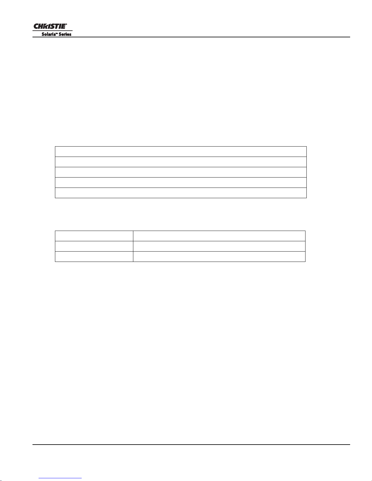
Table 1.1 Purchase Record
Dealer:
Dealer or Christie Sales/Service Contact Phone Number:
Projector Serial Number*:
Purchase Date:
Installation Date:
* The serial number is on the license label located on the front panel of the projector.
Section 1: Introduction
Table 1.2 Ethernet Settings
Default Gateway
Projector IP Address
Subnet Mask
CP4220 User Manual 1-3
020-100690-02 Rev. 1 (01-2012)


2 Installation and Setup
This section explains how to install, connect, and optimize the projector display.
2.1 Site Requirements
To safely install and operate the CP4220 projector, the installation location must meet these minimum
requirements:
• Physical Operating Environment
• Maximum Ambient Temperature (operating) 35°C
• Minimum Ambient Temperature (operating) 10°C
• External Exhaust Ducting
• The installation site must provide a minimum of 450 CFM (ft
adequate cooling of the Xenon arc lamp at less than or equal to 25°C ambient and less than 3,000 feet elevation. Above 25°C or 3,000 feet, 600 CFM is required. For detailed instructions for measuring CFM, see
2.8 Connect External Exhaust Ducting, on page 2-8.
• Permanent Power Connection
• Single-phase projector unit: Maximum 15A circuit breaker protection provided as part of the building
installation
• Three-phase Lamp Power Supply (LPS): Minimum 50A breaker protection must be provided and must
disconnect all phases simultaneously for the stationary permanently connected equipment.
• Protection from overcurrents, short circuits, and earth faults must be part of the building installation.
3
/min) external exhaust airflow to ensure
• 4-wire to Terminal Block in Lamp Power Supply (certified electrician required).
• Protection from overcurrents, short circuits, and earth faults must be part of the building installation. The
disconnect device (double pole switch or circuit breaker with minimum 3mm contact gap) must be readily
accessible within the projection room.
2.2 Tools Required for Installation
You need these tools to install the CP4220 projector:
• 12” screwdrivers: Phillips #2 (magnetic) and flat
• 19mm and 7/8” wrenches
• Assorted Allen keys (metric)
• Heat extractor
• Christie approved protective safety clothing if you are working with the lamp
•Lamp
• Lens cleaning tissue and solution
CP4220 User Manual 2-1
020-100690-02 Rev. 1 (01-2012)
Section 2: Installation and Setup
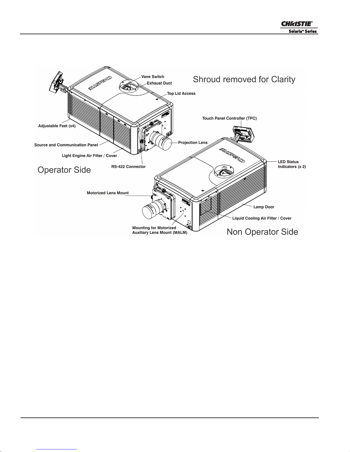
Figure 2-1 Projector Overview
2.3 Projector Components
Air Filter Cover and Air Filter
The air filter filters the intake air before it circulates in the front compartment to cool the main electronics. See
Section 7.11 Replace the Light Engine Air Filter.
Manual Douser Override
Closes the douser. Closing the douser rotates a shutter blade in front of the lamp and reduces lamp power to
2kW to conserve lamp life. The override switch is meant for emergency use only.
Exhaust Duct and Vane Switch
Extracts heated air from the lamp compartment. The vane switch inside the rigid port monitors the amount of
airflow. See Section 2.1 Site Requirements for airflow requirements of the external heat extraction system.
Adjustable Feet
Adjusts the tilting angle of the projector.
2-2 CP4220 User Manual
020-100690-02 Rev. 1 (01-2012)

Section 2: Installation and Setup
Lamp Door and Lamps
Provides access to the lamp. The lamp door must remain closed and locked for normal operation. Lamp
replacement should only be performed by qualified technicians.
The projector 7kW ballast is designed to operate with 2.0kW, 3.0kW, 4.5kW or 6.0kW lamps. See Section
Appendix A: Specifications for a complete list of available lamp types.
LED Status Indicators
Provides information about the status of the projector. See Section 5 Projector Operation for information about
projector status
Motorized Auxiliary Lens Mount (MALM)
An optional auxiliary lens mount can be installed adjacent to the primary lens mount to provide motorized
positioning of a 1.25x Anamorphic lens or a 1.26 Wide Converter lens in front of the primary lens. The Wide
Converter lens “zooms” the image from flat to scope image formats. The Anamorphic lens horizontally
spreads the image back into its wider 2.39:1 “scope” image and is most typically used in side-masking theatres
or on larger screen sizes.
Projection Lens
A variety of lenses can be used with the CP4220 projector. See Section Appendix A: Specifications for a list of
available lenses.
RS-422 Connector
Connects the motorized lens mount to the projector.
Security Locks
Prevents unauthorized access to projector components.
Shroud
Covers the motorized lens mount assembly. The shroud is to be removed for installing a lens, MALM or when
using some 3D equipment.
Input Panel
Connects the projector to external devices such as cinema servers, computers, and controllers.
PIB (Projector Intelligence Board) Faceplate Connections:
10Base-T/100Base-TX Ethernet: Connects the projector to a network.
GPIO: Connects the projector to external Input and output devices, such as the Christie ACT. See Section
3.3 Connecting Devices to the GPIO Port for GPIO pinouts.
DVI-A / DVI-B: Connects the projector to non-cinema video and graphics sources. These are single-link
ports for single-link cables and connectors. The connectors can be used together as a twin-link DVI port.
HD-SDI A/HD-SDI-B: Connects the projector to high-definition cinema sources. The connectors can be
used together to deliver Dual Link HD-SDI following the SMPTE 372M standard.
CP4220 User Manual 2-3
020-100690-02 Rev. 1 (01-2012)

Section 2: Installation and Setup
SCCI: A Simple Contact Closure Interface (SCCI) port that uses a simple dry contact closure to turn the
lamp on or off or to open or close the douser. See Section 3.2 Connecting Devices to the SCCI Port for
SCCI pinouts.
RS232 ICP: Connects a projector to a computer for direct DLP communication.
RS232 PIB: Connects the projector to Christie accessories or third-party automation equipment.
Marriage: Allows the projector to display encrypted content.
Emergency Start: Starts the projector, turns the lamp on, and opens the douser when the Touch Panel
Controller is unavailable or disconnected. Press and hold this button, to close the douser and turn the lamp
off; the power remains on.
Reset: Resets the projector electronics. If the projector is in standby mode, it returns to standby mode after
the reset. If the projector is in any other state, the projector is on and the lamp is off following the reset.
3D: Connects the projector to 3D products, such as MasterImage or Real D for polarizing and de-ghosting
3D content during projection.
ICP Faceplate Connections
The ICP board provides the image processing electronics for the projector. The ICP faceplate includes a
number of LEDs that are only functional when the projector is in full power mode.
• REGEN: (Regulators Enabled) Indicates the presence of the internal regulator enable signal. When illuminated BLUE the internal regulators are enabled. When OFF, not enabled.
• SOFTST: (Software State) Indicates the state of the software application. When OFF, in a Fail state (0).
When RED, in a Fail state (1). When YELLOW, in a Fail state (2). When GREEN, status OK.
• OSST: (Operating System State) Indicates the state of the operating system. When OFF, in a Fail state (0).
When RED, in a Fail state (1), When YELLOW, in a Fail state (2). When GREEN, status OK.
• FMTST: (FMT FPGA State) Indicates the configured state of the FMT FPGA. When RED, unable to con-
figure FPGA with Main or Boot application. When YELLOW, in Boot application. When Green, in Main
application.
• ICPST: (ICP FPGA State) Indicates the configured state of the ICP FPGA. When RED, unable to configure
FPGA with Main or Boot application. When YELLOW, in Boot application. When Green, in Main application.
• Port A / Port B: Indicates the status of the ICP input port A or B. When OFF, no source is present. When
GREEN, an active source is present.
• IMB: Allows the installation of an Image Media Block (IMB).
Touch Panel Controller (TPC)
The TPC is a touch-sensitive screen that you use to control the projector. It is mounted on the rear of the
projector and you can use the flexible connection to adjust the viewing angle. In general, the TPC provides
users with a means for monitoring operation and status of the projector. You typically use the TPC to turn the
lamp on or off, select an input device, and view status information.
You can install the TPC on a wall near the projector, or you can use the optional extension cable to control the
projector from a maximum distance of 100 feet.
2-4 CP4220 User Manual
020-100690-02 Rev. 1 (01-2012)
2.4 Installation Safety and Warning Guidelines
WARNING
WARNING
WARNING
WARNING
WARNING
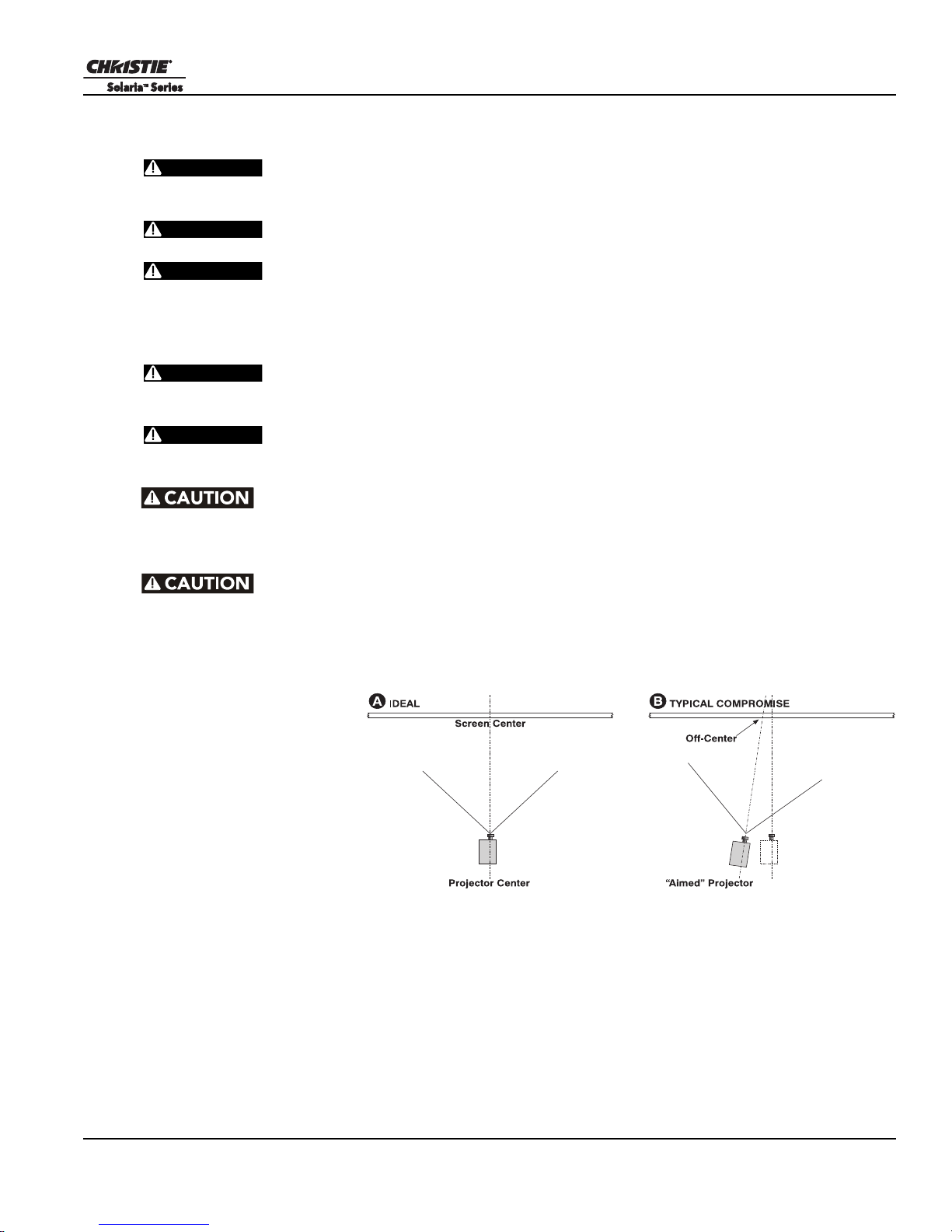
Figure 2-2 Position the Projector
QUALIFIED TECHNICIAN REQUIRED for all installations. This product must be
installed in a restricted access location.
Never operate the projector without the covers in place.
The projector uses a high-pressure lamp that may explode if improperly handled. Always wear manufacturer approved protective safety clothing (gloves, jacket, face
shield) whenever the lamp door is open or when handling the lamp. Only qualified technicians
should install projector lamps.
To prevent the projector from tipping unexpectedly, you must install the
safety strap on the rear of the projector.
Four or more people are required to safely lift and carry one projection head a
short distance. Remove the lamp before transporting the projector.
Keep the projector level when you lift or transport it. Avoid tilting the projector to the right. This can introduce an air bubble into the coolant hoses that can result in an air
lock and the overheating of the projector.
Section 2: Installation and Setup
Perform a automatic LampLOC™ adjustment when you move, level, or install a
new lamp in the projector.
2.5 Position the Projector
1. Position the projector at an
appropriate throw distance
(projector-to-screen
distance) and vertical
position. Ideally, center the
projector with the theatre
screen. If space is limited,
aim the projector slightly
off-center as shown in
Figure 2-2. This increases
side keystoning, but
reduces the horizontal lens
offset required.
2. Attach the supplied safety strap to the back of the projector and fasten it to its mounting surface. Use of the
strap is mandatory to prevent the projector from tipping when a lens or auxiliary lens mount is installed.
NOTE: Unlike film projectors, it is best to keep the projector lens surface as parallel to the screen as possible,
even if significantly above the screen center. When a particularly short throw distance combines with a very
wide screen, you may have to forfeit some aim and stay more parallel to the screen. In such cases, some lens
offset can reduce the keystone distortion.
CP4220 User Manual 2-5
020-100690-02 Rev. 1 (01-2012)
Section 2: Installation and Setup
WARNING
WARNING
Figure 2-3 Adjust Feet
2.6 Adjust Tilt and Level the Projector
The projector’s rear safety strap must be in place before you adjust the
projector’s feet.
DO NOT over-extend the feet. Make sure several threads are engaged into
the projector’s baseplate.
The CP4220 lens should be centered and parallel with the screen. This orientation ensures optimum lens
performance with minimal offset. If this position is not possible (such as when the projector is significantly
higher than the center of the screen), it is better to rely on offset rather than extra tilt.
Use a protractor to measure the degree of screen tilt and then extend or retract the projector feet to match this
angle.
NOTE: The front-to-back tilt of the projector must not exceed 15°. This limit ensures safe lamp operation and
the proper positioning of the liquid cooling reservoir
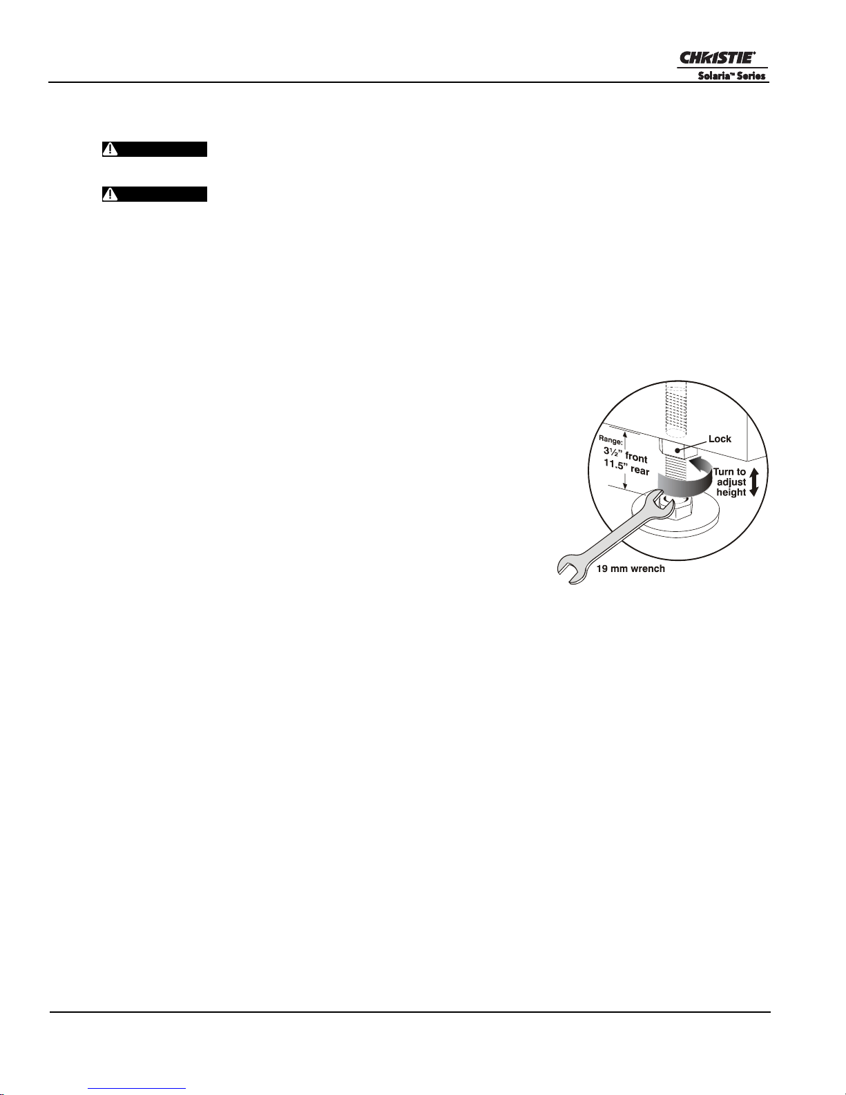
To adjust the vertical or horizontal position of the projector, extend or
retract the adjustable feet on the bottom of the projector by rotating them.
Once the required adjustment is made, tighten the lock nut.
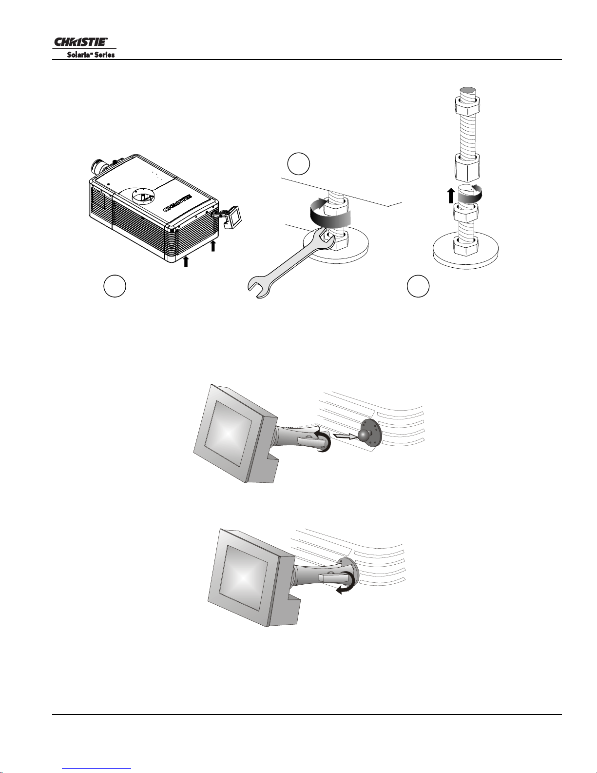
If you need to adjust the vertical or horizontal position of the projector
beyond what the standard feet allow, you can install two 6 inch extension
rods to increase the amount of adjustment. To install the extension rods
safely:
1. Prop the rear of the projector up to access and remove the two rear
feet. This can be done by one person holding the back end of the
projector up slightly so another person can unthread the feet OR by
propping up the back of the projector with a sturdy object.
2. Add the extension rods to the standard feet.
3. Thread the newly extended feet back into the projector’s baseplate.
Adjust the feet until the desired tilt is achieved.
4. Lock the feet in place by turning each lock nut until it fits tight against the projector.
2-6 CP4220 User Manual
020-100690-02 Rev. 1 (01-2012)
Section 2: Installation and Setup
19 mm wrench
Remove rear feet
Prop up rear of projector
Add foot extension rod
2.
1.
3.
Figure 2-4 Using the Foot Extension Rods
Figure 2-5
Figure 2-6
2.7 Install the Touch Panel Controller (TPC)
1. Loosen the mounting arm so that the end fits over the ball joint located on the rear panel of the projector.
2. Tighten the mounting arm until it fits tightly on the joint.
3. Connect the cable from the TPC to the connector on the rear panel of the projector.
4. Adjust the angle of the TPC.
CP4220 User Manual 2-7
020-100690-02 Rev. 1 (01-2012)
Section 2: Installation and Setup
Figure 2-7 Connect Exhaust Ducting
WARNING
Figure 2-8 Exhaust Duct Vane Switch
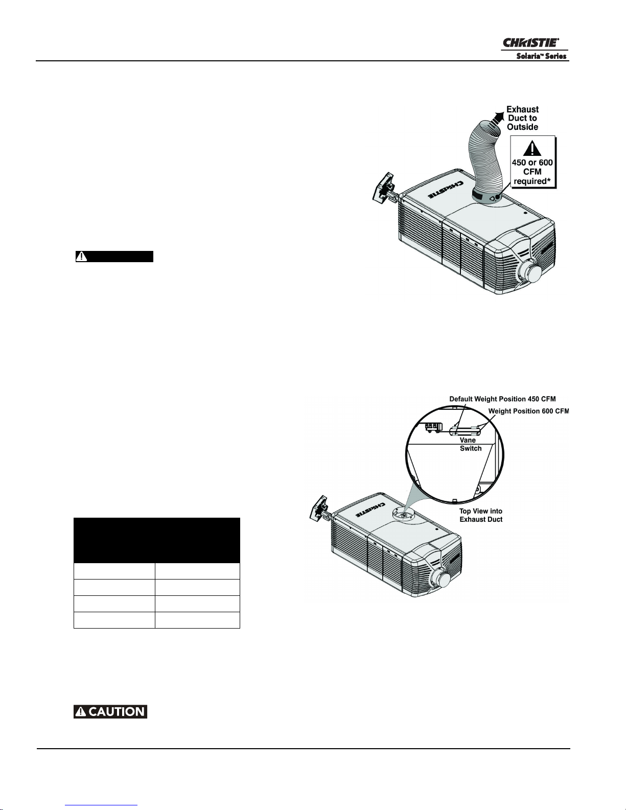
2.8 Connect External Exhaust Ducting
Connect the existing outside-venting ductwork to the 8 inch
diameter exhaust port on the top of the projector. Confirm that
there are no obstructions or bends in the ducting, all air intakes
are free of obstructions, and the vane switch at the exit duct
moves freely.
The pre-installed outside-venting duct should be rigid at the
projector and must also include a heat extractor and blower that
maintains a minimum of 450 CFM* when the projector is
operating at less than or equal to 25°C ambient and less than
3,000 feet, when measured at the projector exhaust opening.
• *600 CFM is required in projection rooms with an
ambient temperature above 25°C or located at an
elevation greater than 3000 feet above sea level.
• At minimum, a 10” long, strong metal duct must be
installed at the projector to prevent glass shards
from exiting the duct in the event of a lamp explosion.
2.8.1 Determine the Projector Exhaust CFM Value
Use an airflow meter to measure the ft/min or ft/
sec at the rigid end of the open exhaust duct that
connects to the projector. Take the measurement
at the very end of the duct without the projector
connected. Use this formula to determine the
CFM value for the projector:
Measured linear ft/min x 0.35 = CFM
Table 2.1 Airflow Requirement
Min.
Lamp Type
2.0 kW 450 CFM*
3.0 kW 450 CFM*
4.5 kW 600 CFM
6.0 kW 600 CFM
Add an extractor or a booster if there is insufficient airflow. Do not mount the extractor on the projector as this
may introduce some vibration into the image. NOTE: To prevent the projector from overheating or becoming
unsafe, an alarm sounds if the duct is obstructed or a fan fails. It is recommended that you regularly verify that
the exhaust is functioning correctly.
Airflow (CFM)
Required
Never disable the vane switch. Attempting to operate the projector with inad-
equate airflow can result in dangerous overheating of the projector.
2-8 CP4220 User Manual
020-100690-02 Rev. 1 (01-2012)
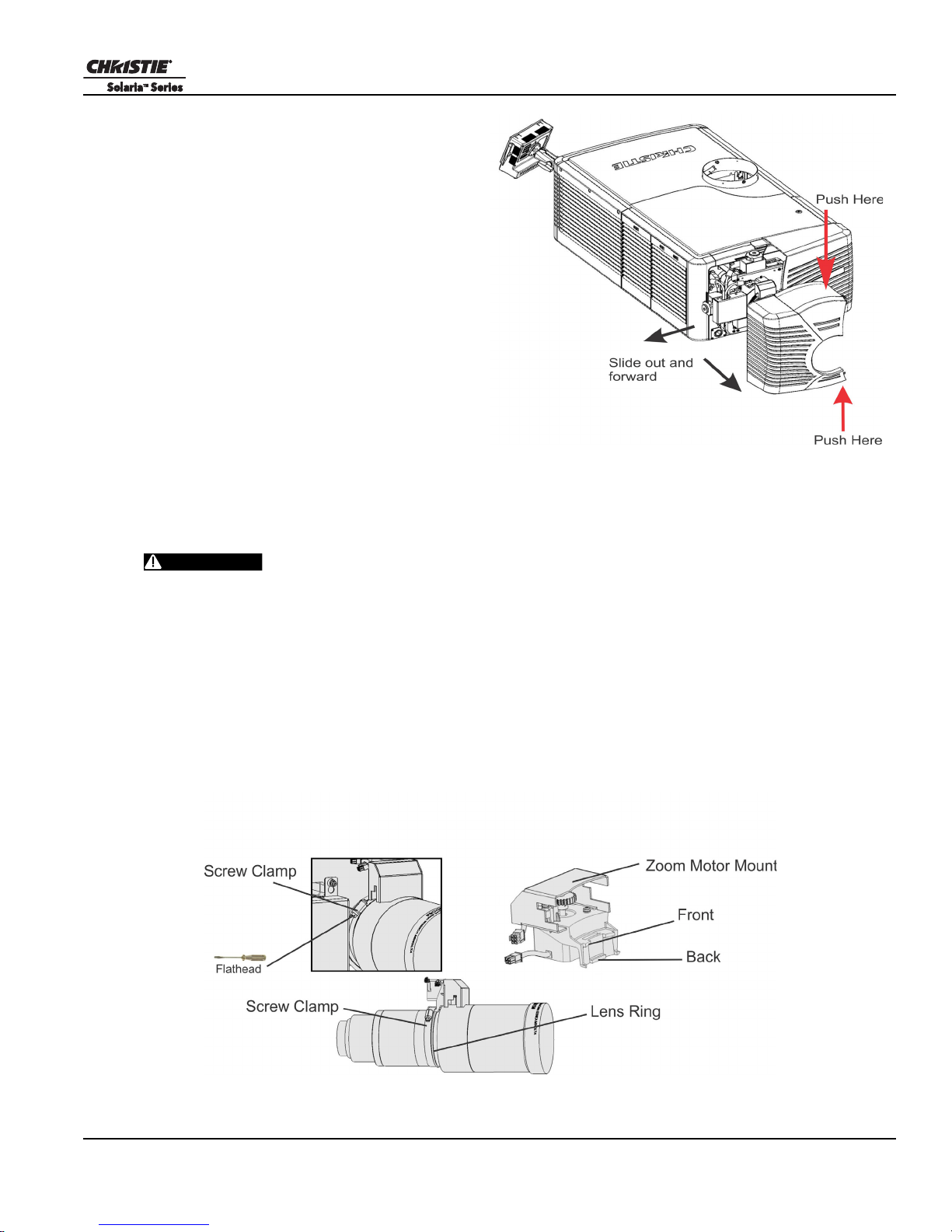
2.9 Remove the Shroud
Figure 2-9 Shroud Removal
WARNING
To access the MLM and lens, you need to remove
one shroud. Remove the second shroud when you
use a Motorized Auxiliary Lens Mount or a Real
D Z.
1. Using finger pressure, push down on the
locations specified by the red arrows in the
diagram.
2. Carefully slide the shroud sideways and
forward away from the MLM and lens.
3. Place the shroud cover on a clean surface to
prevent scratches.
2.10 Install the Primary Lens
The lens seals the projection head, preventing contaminants from entering the main electronics area. Do not
operate the projector without a lens installed. Install a lens plug when you install or transport the projector.
Section 2: Installation and Setup
To prevent a collision between the projection lens and the Motorized Auxiliary
Lens Mount (MALM), move it to the OUT position before you calibrate the lens or perform
reset functions. Keep your fingers and other body parts away from the moving parts in the
projector. Motors and fans may start without warning. Tie back long hair, remove jewelry and
loose clothing before manually adjusting the projector.
NOTE: 1) Make sure the zoom ring is against the front of motor mount for lenses: 1.6-2.4:1, 1.8-3.0:1, 2.15-
3.6:1. 2) Make sure the zoom ring is against the back of motor mount for lenses: 1.45-2.05:1, 1.25-1.83:1. 3)
All other lenses: Leave a gap between the rotating zoom section of lens and motor mount.
1. Unpack the zoom motor kit.
2. Use a flathead screwdriver to install the zoom motor mount onto the lens with a screw clamp.
CP4220 User Manual 2-9
020-100690-02 Rev. 1 (01-2012)
Section 2: Installation and Setup
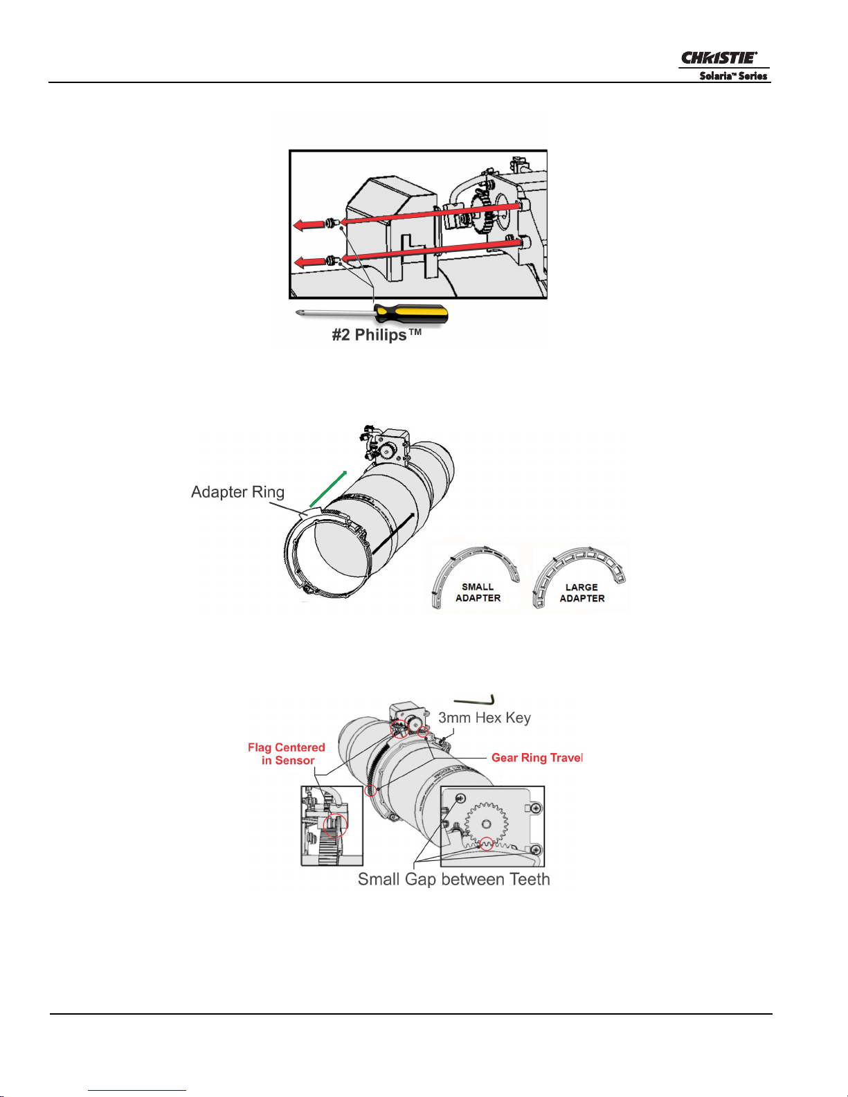
3. Remove the cover from the zoom motor mount with a Phillips screwdriver. Keep the hardware and cover.
4. Install zoom gear ring and adapter onto the lens.
NOTE: 1) Use a small adapter for lens 1.8-3.0. 2) Use a large adapter for lens 1.45-2.05, 2.15-3.6, 1.25-
1.83:1 3) All other lenses do not need an adapter.
5. Verify that there is full travel of the gear ring, and the alignment of the sensor is correct.
NOTE: There must be a small gap between the gears to prevent binding. To ensure there is a gap, loosen
the screws and readjust the gap. Tighten the screws when you have completed the adjustment.
Figure 2-10
2-10 CP4220 User Manual
020-100690-02 Rev. 1 (01-2012)
Section 2: Installation and Setup
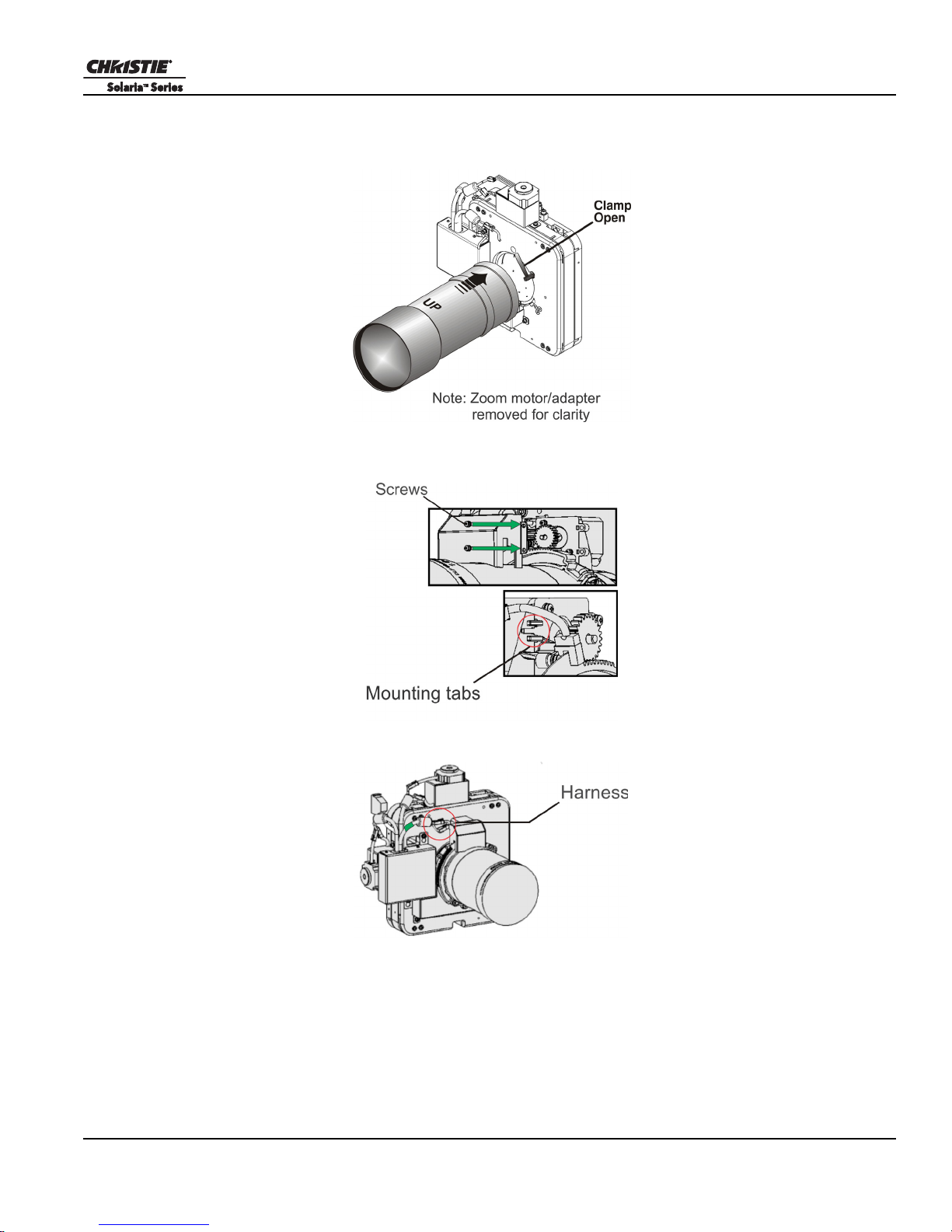
6. Turn the lens clamp to the OPEN position on the MLM and fully insert the assembly straight into the lens
mount opening without turning. When the lens is fully inserted it is seated properly within the lens mount
and the aperture is installed correctly.
7. Install the cover with the screws.
NOTE: Make sure the cover is between the mounting tabs.
8. Connect the harness wires.
CP4220 User Manual 2-11
020-100690-02 Rev. 1 (01-2012)
Section 2: Installation and Setup
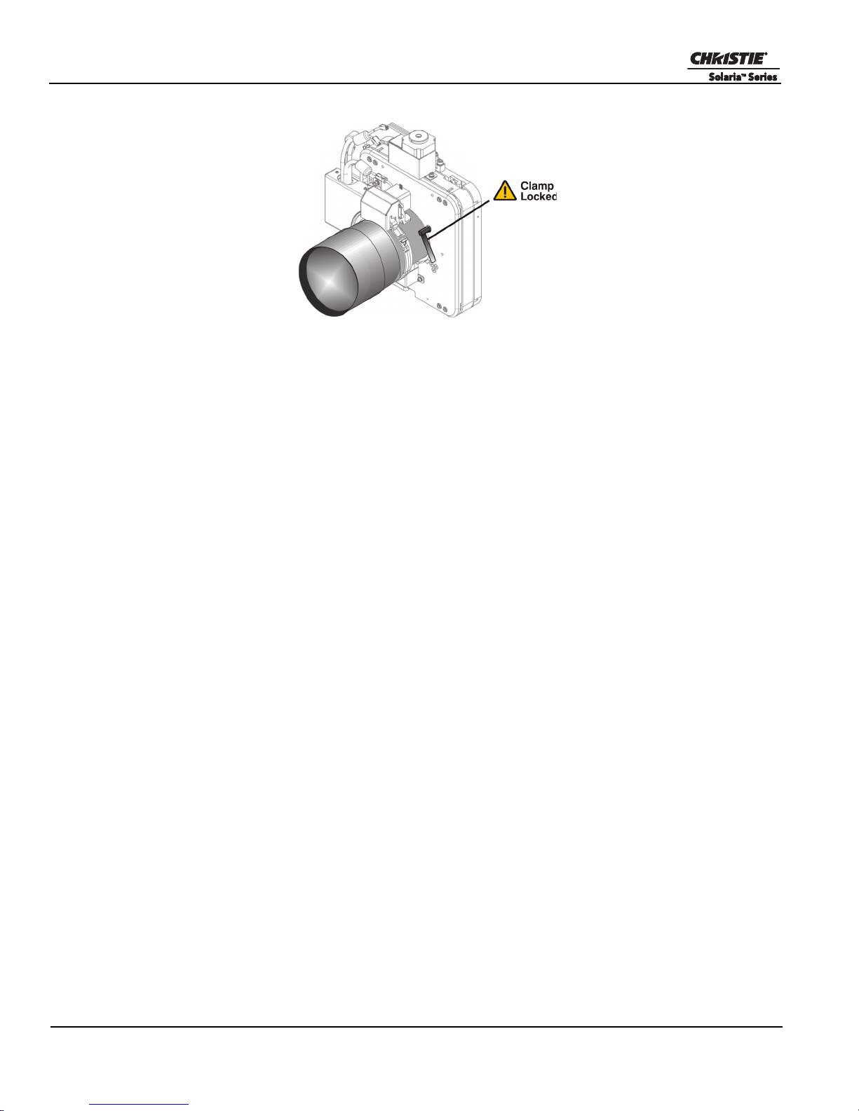
9. Position the lens clamp DOWN to lock the lens assembly in place.
10. Calibrate the lens. See Section 4.3 Basic Image Alignment for details.
11. Install the shroud.
2.11 Install the Optional Anamorphic Lens
1. Make sure to optimize your primary lens first for best optical alignment, offset and boresight.
2. Install the auxiliary lens mount using the instructions included with the kit.
3. Loosen the holding clamp on the auxiliary lens mount. Adjust the rotation of the anamorphic lens so the
image remains perfectly square with anamorphic in and out.
4. Adjust the location of the anamorphic lens so that the image does not shift left or right with the anamorphic
lens in and out.
5. Adjust the location of the anamorphic lens so the image passes through the center as much as possible
without vignetting, reducing side or corner brightness, especially in wide angle projection.
6. Remove the anamorphic lens and turn the Focus knob to re-focus the primary lens. The goal is for good
focus at the center and on all sides.
7. Re-install the anamorphic lens and check the focus.
8. If center-to-edge horizontal focus in the image needs improvement, rotate the focus barrel.
2.12 Install the Optional Wide Converter Lens
1. Optimize the primary projector lens for optical alignment, offset, and boresight.
2. Install the Auxiliary Lens Mount and Wide Converter Lens (WCL) using the instructions included with the
kit.
3. Adjust the vertical and horizontal position of the WCL to align it with the primary lens.
4. Adjust the pitch, up or down to equalize the top and bottom clearance to the primary lens barrel.
5. Adjust yaw to make the clearance between both lens barrels equal from side-to-side.
2-12 CP4220 User Manual
020-100690-02 Rev. 1 (01-2012)
2.13 Install the Lamp
DANGER
DANGER
Reflector
Anode
Yok e
Assembly
5mm hex key
required
Figure 2-11 Yoke assembly installa-
This procedure should only be performed by a Christie accredited technician.
High-pressure lamp may explode if improperly handled. Always wear approved protective
safety clothing whenever lamp door is open or when handling the lamp.
1. If the projector is operating, turn it off and allow it to cool a minimum of 10 minutes.
2. Turn the breaker switch for the projector off.
3. Disconnect the projector from AC power.
4. Put on your protective clothing and face shield.
5. Use the security key to open the lamp door and access the lamp cooling compartment. Do not place heavy
objects on the open lamp door.
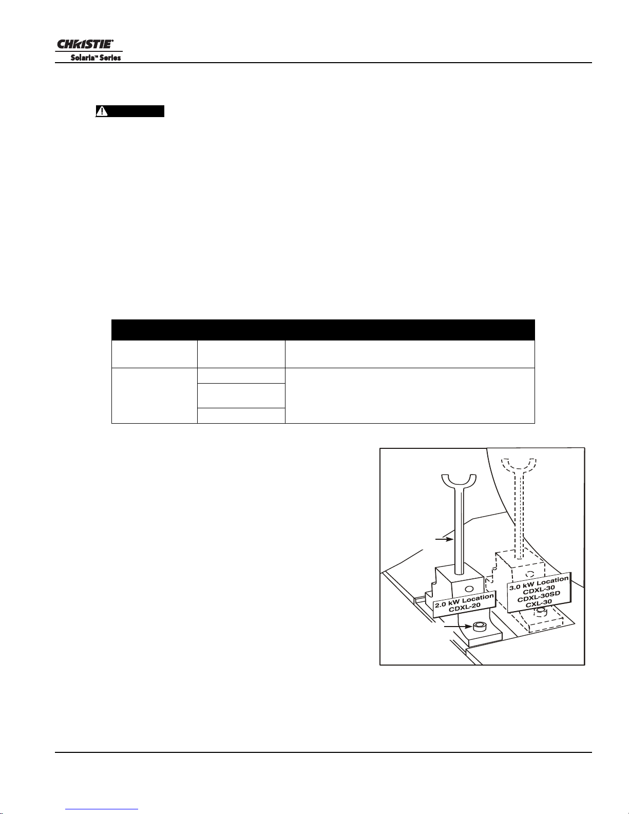
6. Install the anode yoke assembly. Use this table to determine the correct position of the anode yoke
assembly.
Table 2.2 Lamp Types Available for CP4220 and Anode Yoke Position
LAMP TYPE ANODE YOKE POSITION
Section 2: Installation and Setup
2.0 kW
3.0 kW
CDXL-20
CDXL-30
CDXL-30SD (short
arc)
CXL-30
Move the lamp cradle as far forward as possible (position
closest to igniter)
Move the lamp cradle to the rear position, which is approximately
1” closer to the reflector.)
7. Install the lamp. See Section 7.9 Replace the Lamp for
lamp replacement instructions. Observe all warnings,
and wear protective safety gear.
CP4220 User Manual 2-13
020-100690-02 Rev. 1 (01-2012)
Section 2: Installation and Setup
WARNING
WARNING
Figure 2-12
2.14 Connect the Projector to AC Power with a Permanent Connection
1) Certified electrician required. 2) Ground (earth) connection is necessary for
safety. Never compromise safety by returning the current through the ground. 3) Connect
ground FIRST
the cable from rubbing against the projector knockout plate and becoming damaged.
When connecting the projector to AC power, follow all electrical codes for your location. In addition, follow
these recommendations:
•A 30-32A double pole, UL listed wall circuit breaker is required. It must be part of the building installation
and easily accessible.
• Use 10AWG or 8AWG wiring. The distance between the wall circuit breaker and the projector must not
exceed 20 meters using 10AWG cables or 30 meters using 8AWG cables.
• For North American installations, use at least 10AWG copper wires for the connection of the main AC supply to the projector’s ground lug.
• Copper or aluminum are acceptable as conductor wiring material to the terminal block.
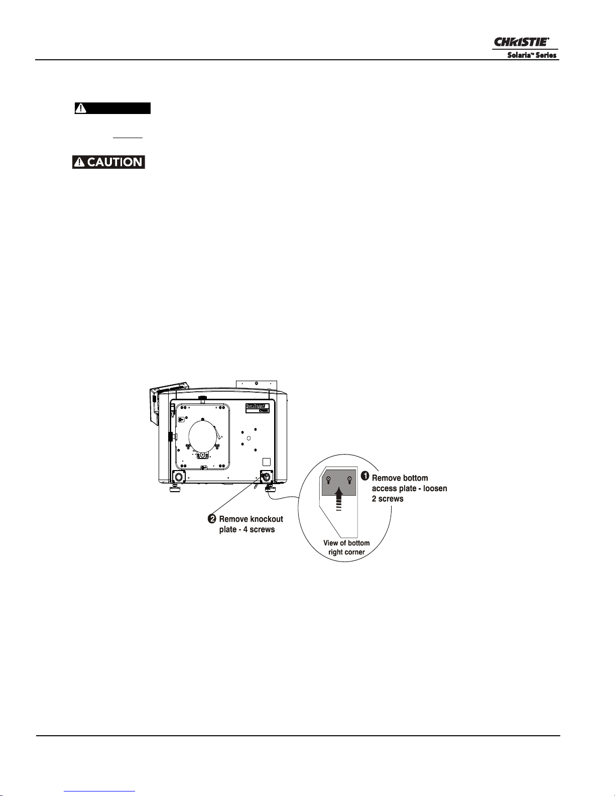
1. On the bottom of the projector in the front right corner, loosen the two screws and slide the plate forward to
expose the terminal block.
to reduce shock hazard from high leakage.
Use an appropriate strain relief connector on the AC supply cable to prevent
2. Remove the knockout plate located in the bottom right corner of the front bezel. The AC supply is routed
to the terminal block through an appropriate strain relief mounted on this knockout plate.
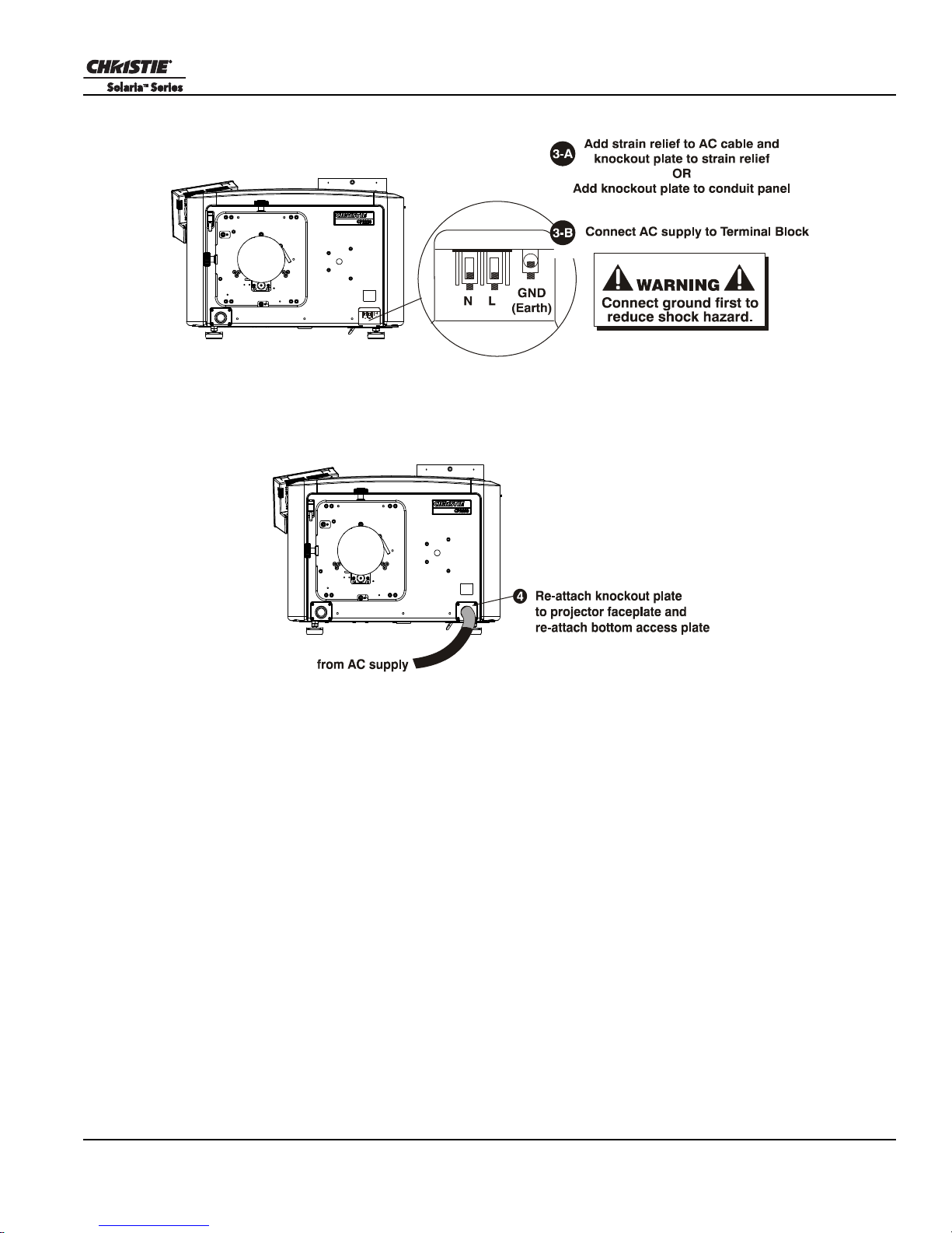
3. Connect the AC power source to the terminal block, beginning with the ground lead first. Use an
appropriately sized strain relief connector with the knockout plate provided to ensure adequate
environmental sealing and to prevent the cables from wear and accidentally being torn out. NOTES: 1)
The terminal block accommodates up to an 8 AWG wire. 2) If desired, a 90° strain relief connector can be
used to route the power cable in a downward direction.
2-14 CP4220 User Manual
020-100690-02 Rev. 1 (01-2012)
Section 2: Installation and Setup
Figure 2-13
Figure 2-14
4. Replace the knockout plate and the bottom access panel over the terminal block.
CP4220 User Manual 2-15
020-100690-02 Rev. 1 (01-2012)
Section 2: Installation and Setup
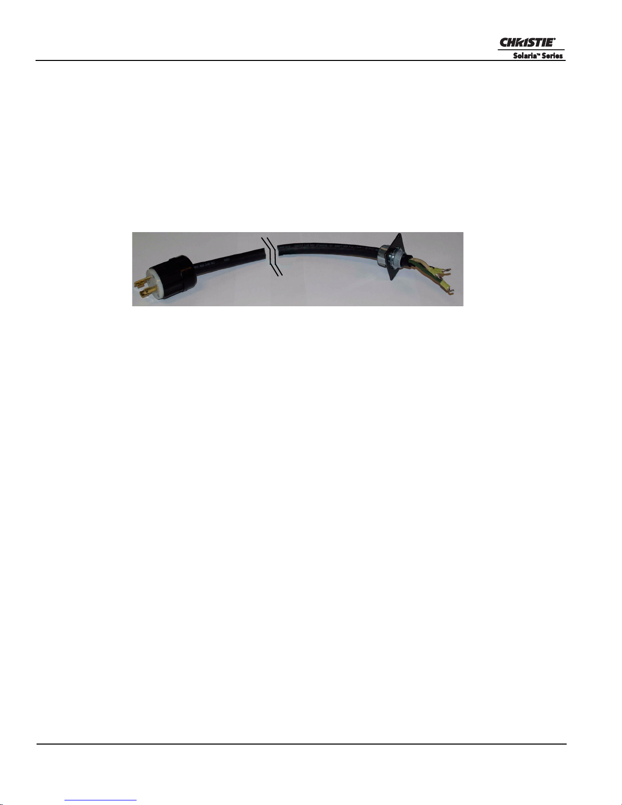
Figure 2-15 Nema-L630A 250V Male Power Plug (116-102104-01)
Actual Length 1.5 Meters
2.15 Connect the Projector to AC Power with a Pluggable Type B Connection
When connecting the projector to AC power, follow all electrical codes for your location. In addition, follow
these recommendations:
• There must be easy access to the current protection device or breaker in the building.
• Use 10AWG or 8AWG wiring: the distance between the wall circuit breaker and the projector must not
exceed 20 meters using 10AWG cables or 30 meters using 8AWG cables.
• The socket-outlet is installed near the equipment and is easily accessible.
• The plug can be used as the device disconnect and is near the unit and easily accessible.
1. On the bottom of the projector in the front right corner, loosen the two screws and slide the plate forward to
expose the terminal block.
2. Remove the knockout plate (four screws) located in the bottom right corner of the front bezel.
3. Connect the AC power source to the terminal block, beginning with the ground lead first. Tighten screws
securely.
4. Secure the knockout plate (four screws) and the bottom access panel (two screws) over the terminal block.
2-16 CP4220 User Manual
020-100690-02 Rev. 1 (01-2012)
 Loading...