

Page 1
Replacing the PCM
Instruction Sheet
INTRODUCTION
Use the following instructions when replacing or upgrading a Processor Control Module (PCM) in
CP2000-ZX and CP2000-M/MR projectors.
The entire procedure requires access to the cardcage, complete removal of the PCM assembly, and in
CP2000-M/MR 119-101101-01 models installing a new faceplate when upgrading from a 3.1 PCM
(001-100536-03/04) to a 4.1 PCM (001-100536-06). The entire procedure can take up to 20 minutes to
complete and should be performed by a qualified service technician.
KITS REQUIRED
003-002884-01 PCM Kit (includes PCM #001-100536-06 board only)
003-100536-06 PCM Kit (includes PCM #001-100536-06 board, faceplates for CP2000-ZX and
CP2000-M/MR and required hardware)
NOTE: The PCM comes pre-assembled with the
CP2000-ZX faceplate.
SAFETY AND WARNING GUIDELINES
HIGH VOLTAGES MAY BE EXPOSED: Always power down and disconnect power
sources prior to servicing. Once the projector is powered down, allow the cooling fans to
automatically turn OFF before disconnecting from AC and opening the projector. Depending on
your projector model this can take 10-15 minutes.
QUALIFIED SERVICE TECHNICIANS REQUIRED: All module replacement
procedures must be performed by qualified service technicians.
NON-INSULATED DANGEROUS VOLTAGES MAY BE EXPOSED: Always
disconnect from AC prior to disassembly.
OBSERVE ALL ELECTROSTATIC PRECAUTIONS: Use a grounded wrist strap
when handling electronic assemblies.
Never operate the projector (or the fans) without all the covers installed.
Replacing the PCM Instruction Sheet 1 of 5
020-100369-01 Rev. 1 (06-2009)
Page 2
TOOLS REQUIRED
Figure 1
Figure 2
• #1, #2 Phillips screwdriver
• 3/16” nut driver
INSTRUCTIONS
FOR CP2000-ZX (KIT #003-100536-01):
OBSERVE ALL ELECTROSTATIC PRECAUTIONS: Use a grounded wrist strap
when handling electronic assemblies.
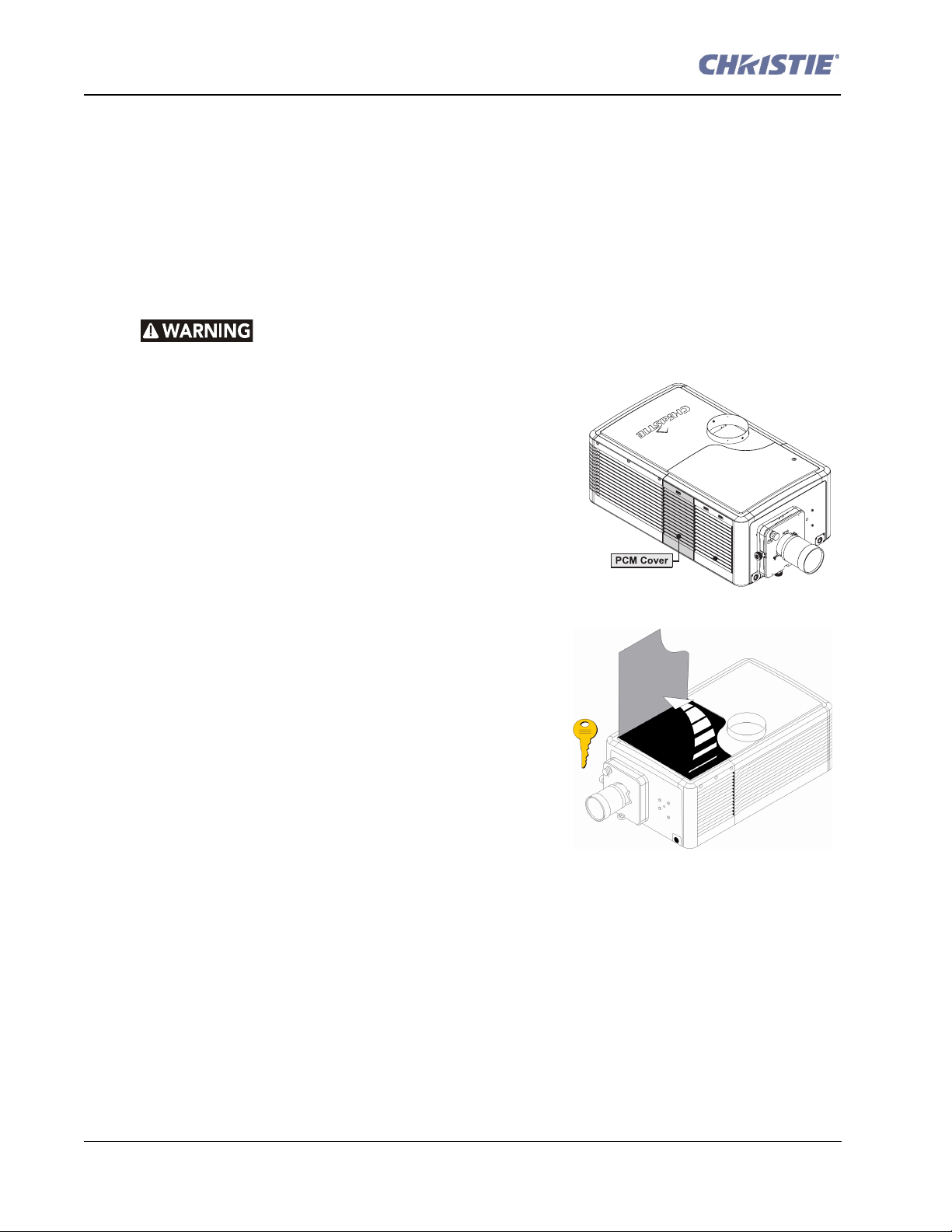
1. Remove the PCM cover to access the Communication
Panel.
a. Push on the tab at the top of the cover (Figure 1).
b. Tilt the cover slightly then lift enough to clear tabs at
the bottom and remove.
2. Remove the front lid. (Figure 2)
a. Unlock the front lid using the high security key.
b. Raise the lid and slide it out from the opposite side to
remove.
3. Using a #2 Phillips, remove the four screws securing the
PCM faceplate; two from the inside and two from the
outside.
4. Pull the PCM assembly out of the cardcage.
5. Slide the new PCM assembly into the cardcage and
secure using the four screws from Step 3.
6. Replace the front lid and PCM cover.
2 of 5 Replacing the PCM Instruction Sheet
020-100369-01 Rev. 1 (06-2009)
Page 3

FOR CP2000-M/MR:
Figure 3 Remove Top Lid
Figure 4 Remove High Security
Cover
OBSERVE ALL ELECTROSTATIC PRECAUTIONS: Use a grounded wrist strap
when handling electronic assemblies.
Do not downgrade software to 2.0 or lower on projectors with a 4.1 PCM.
Replacing a PCM in -02 models or higher (Kit #003-002884-01)
1. Remove the projector’s top lid. (Figure 3)
a. Use a #2 Phillips to loosen the seven captive screws
securing the top lid to the projector frame.
b. Unlock the rear access door using the low security key.
c. Lift the lid up from the rear of the projector and pull it
away from the two tabs on the front skin.
2. Remove the six screws securing the high security cover.
(Figure 4) Unlock the high security access lock. Lift the
lid and slide it out.
Replacing the PCM Instruction Sheet 3 of 5
020-100369-01 Rev. 1 (06-2009)
Page 4

3. Remove the clips securing the harnesses to the cardcage
Figure 5 Remove Harness Clips
Figure 6
(Figure 5).
4. Use a #2 Phillips to loosen the two thumbscrews at the
top of the cardcage.
5. Remove three screws from each side of the
two faceplates. (Figure 6) Do not remove
the center screws just yet. This will allow
you to pull the cardcage out a few
centimeters. Only apply force to the top
edges of the handles only.
6. With the cardcage out slightly, remove four
screws from each side of the cardcage.
7. Remove the four center screws securing
both faceplates to the cardcage. (Figure 6)
8. Tilt the I/O faceplate slightly to allow
removal of the PCM assembly.
9. Separate the PCM faceplate from the PCM PCB:
a. Remove the two nuts securing the BNC’s to the faceplate (2x 9/16”).
b. Using a nut driver, remove the six standoffs (3/16”) securing the DVI-D A, DVI-D B and the
‘RS-232’ B connectors to the faceplate.
c. Remove the two screws securing the faceplate to the PCM PCB. Reuse the faceplate with the
new PCM PCB.
10. Secure the new PCM PCB in the kit to the faceplate repeating the above instructions in reverse and
reusing the hardware from the old PCM assembly.
Upgrading the PCM in -01 models (Kit # 003-100536-06)
1. Perform Steps 1 - 8 in the procedure above.
2. Swap the faceplate on the PCM assembly with the loose one in the kit (Figure 8). Note: The
faceplate attached to the PCM in the kit belongs to the CP2000-ZX.
a. Remove the two nuts securing the BNC’s to the faceplate (2x 9/16”).
b. Remove the six standoffs (3/16”) securing the DVI-D A, DVI-D B and the ‘RS-232’ B con-
nectors to the faceplate. (Figure 7)
4 of 5 Replacing the PCM Instruction Sheet
020-100369-01 Rev. 1 (06-2009)
Page 5

c. Using a #1 Phillips, remove the two screws from the L-shaped bracket securing the faceplate
Figure 7 Separate ZX Faceplate from PCM
Figure 8 New PCM Faceplate
Figure 9 New PCM Assembly Installed
to the PCM. (Figure 7)
d. Install the new CP2000-M/MR faceplate
(Figure 8) to the PCM, repeating the
above steps in reverse and reusing the
hardware.
e. Fasten the two handles from the kit to the
faceplate. Tighten screws to a torque setting of 3.5 in-lbs.
3. Slide the new PCM assembly into the
cardcage. Repeat steps above in
reverse to secure PCM assembly.
(Figure 9)
Replacing the PCM Instruction Sheet 5 of 5
020-100369-01 Rev. 1 (06-2009)
 Loading...